CN110709114A - Heart Pump Drives and Bearings - Google Patents
Heart Pump Drives and Bearings Download PDFInfo
- Publication number
- CN110709114A CN110709114A CN201880037512.1A CN201880037512A CN110709114A CN 110709114 A CN110709114 A CN 110709114A CN 201880037512 A CN201880037512 A CN 201880037512A CN 110709114 A CN110709114 A CN 110709114A
- Authority
- CN
- China
- Prior art keywords
- bearing
- driver
- heart pump
- impeller
- cavity
- Prior art date
- Legal status (The legal status is an assumption and is not a legal conclusion. Google has not performed a legal analysis and makes no representation as to the accuracy of the status listed.)
- Granted
Links
Images


Classifications
-
- A—HUMAN NECESSITIES
- A61—MEDICAL OR VETERINARY SCIENCE; HYGIENE
- A61M—DEVICES FOR INTRODUCING MEDIA INTO, OR ONTO, THE BODY; DEVICES FOR TRANSDUCING BODY MEDIA OR FOR TAKING MEDIA FROM THE BODY; DEVICES FOR PRODUCING OR ENDING SLEEP OR STUPOR
- A61M60/00—Blood pumps; Devices for mechanical circulatory actuation; Balloon pumps for circulatory assistance
- A61M60/20—Type thereof
- A61M60/205—Non-positive displacement blood pumps
- A61M60/216—Non-positive displacement blood pumps including a rotating member acting on the blood, e.g. impeller
- A61M60/226—Non-positive displacement blood pumps including a rotating member acting on the blood, e.g. impeller the blood flow through the rotating member having mainly radial components
- A61M60/232—Centrifugal pumps
-
- A—HUMAN NECESSITIES
- A61—MEDICAL OR VETERINARY SCIENCE; HYGIENE
- A61M—DEVICES FOR INTRODUCING MEDIA INTO, OR ONTO, THE BODY; DEVICES FOR TRANSDUCING BODY MEDIA OR FOR TAKING MEDIA FROM THE BODY; DEVICES FOR PRODUCING OR ENDING SLEEP OR STUPOR
- A61M60/00—Blood pumps; Devices for mechanical circulatory actuation; Balloon pumps for circulatory assistance
- A61M60/10—Location thereof with respect to the patient's body
- A61M60/122—Implantable pumps or pumping devices, i.e. the blood being pumped inside the patient's body
- A61M60/126—Implantable pumps or pumping devices, i.e. the blood being pumped inside the patient's body implantable via, into, inside, in line, branching on, or around a blood vessel
- A61M60/148—Implantable pumps or pumping devices, i.e. the blood being pumped inside the patient's body implantable via, into, inside, in line, branching on, or around a blood vessel in line with a blood vessel using resection or like techniques, e.g. permanent endovascular heart assist devices
-
- A—HUMAN NECESSITIES
- A61—MEDICAL OR VETERINARY SCIENCE; HYGIENE
- A61M—DEVICES FOR INTRODUCING MEDIA INTO, OR ONTO, THE BODY; DEVICES FOR TRANSDUCING BODY MEDIA OR FOR TAKING MEDIA FROM THE BODY; DEVICES FOR PRODUCING OR ENDING SLEEP OR STUPOR
- A61M60/00—Blood pumps; Devices for mechanical circulatory actuation; Balloon pumps for circulatory assistance
- A61M60/10—Location thereof with respect to the patient's body
- A61M60/122—Implantable pumps or pumping devices, i.e. the blood being pumped inside the patient's body
- A61M60/165—Implantable pumps or pumping devices, i.e. the blood being pumped inside the patient's body implantable in, on, or around the heart
- A61M60/178—Implantable pumps or pumping devices, i.e. the blood being pumped inside the patient's body implantable in, on, or around the heart drawing blood from a ventricle and returning the blood to the arterial system via a cannula external to the ventricle, e.g. left or right ventricular assist devices
- A61M60/183—Implantable pumps or pumping devices, i.e. the blood being pumped inside the patient's body implantable in, on, or around the heart drawing blood from a ventricle and returning the blood to the arterial system via a cannula external to the ventricle, e.g. left or right ventricular assist devices drawing blood from both ventricles, e.g. bi-ventricular assist devices [BiVAD]
-
- A—HUMAN NECESSITIES
- A61—MEDICAL OR VETERINARY SCIENCE; HYGIENE
- A61M—DEVICES FOR INTRODUCING MEDIA INTO, OR ONTO, THE BODY; DEVICES FOR TRANSDUCING BODY MEDIA OR FOR TAKING MEDIA FROM THE BODY; DEVICES FOR PRODUCING OR ENDING SLEEP OR STUPOR
- A61M60/00—Blood pumps; Devices for mechanical circulatory actuation; Balloon pumps for circulatory assistance
- A61M60/10—Location thereof with respect to the patient's body
- A61M60/122—Implantable pumps or pumping devices, i.e. the blood being pumped inside the patient's body
- A61M60/196—Implantable pumps or pumping devices, i.e. the blood being pumped inside the patient's body replacing the entire heart, e.g. total artificial hearts [TAH]
-
- A—HUMAN NECESSITIES
- A61—MEDICAL OR VETERINARY SCIENCE; HYGIENE
- A61M—DEVICES FOR INTRODUCING MEDIA INTO, OR ONTO, THE BODY; DEVICES FOR TRANSDUCING BODY MEDIA OR FOR TAKING MEDIA FROM THE BODY; DEVICES FOR PRODUCING OR ENDING SLEEP OR STUPOR
- A61M60/00—Blood pumps; Devices for mechanical circulatory actuation; Balloon pumps for circulatory assistance
- A61M60/20—Type thereof
- A61M60/205—Non-positive displacement blood pumps
- A61M60/216—Non-positive displacement blood pumps including a rotating member acting on the blood, e.g. impeller
-
- A—HUMAN NECESSITIES
- A61—MEDICAL OR VETERINARY SCIENCE; HYGIENE
- A61M—DEVICES FOR INTRODUCING MEDIA INTO, OR ONTO, THE BODY; DEVICES FOR TRANSDUCING BODY MEDIA OR FOR TAKING MEDIA FROM THE BODY; DEVICES FOR PRODUCING OR ENDING SLEEP OR STUPOR
- A61M60/00—Blood pumps; Devices for mechanical circulatory actuation; Balloon pumps for circulatory assistance
- A61M60/40—Details relating to driving
- A61M60/403—Details relating to driving for non-positive displacement blood pumps
- A61M60/419—Details relating to driving for non-positive displacement blood pumps the force acting on the blood contacting member being permanent magnetic, e.g. from a rotating magnetic coupling between driving and driven magnets
-
- A—HUMAN NECESSITIES
- A61—MEDICAL OR VETERINARY SCIENCE; HYGIENE
- A61M—DEVICES FOR INTRODUCING MEDIA INTO, OR ONTO, THE BODY; DEVICES FOR TRANSDUCING BODY MEDIA OR FOR TAKING MEDIA FROM THE BODY; DEVICES FOR PRODUCING OR ENDING SLEEP OR STUPOR
- A61M60/00—Blood pumps; Devices for mechanical circulatory actuation; Balloon pumps for circulatory assistance
- A61M60/40—Details relating to driving
- A61M60/403—Details relating to driving for non-positive displacement blood pumps
- A61M60/422—Details relating to driving for non-positive displacement blood pumps the force acting on the blood contacting member being electromagnetic, e.g. using canned motor pumps
-
- A—HUMAN NECESSITIES
- A61—MEDICAL OR VETERINARY SCIENCE; HYGIENE
- A61M—DEVICES FOR INTRODUCING MEDIA INTO, OR ONTO, THE BODY; DEVICES FOR TRANSDUCING BODY MEDIA OR FOR TAKING MEDIA FROM THE BODY; DEVICES FOR PRODUCING OR ENDING SLEEP OR STUPOR
- A61M60/00—Blood pumps; Devices for mechanical circulatory actuation; Balloon pumps for circulatory assistance
- A61M60/80—Constructional details other than related to driving
- A61M60/802—Constructional details other than related to driving of non-positive displacement blood pumps
- A61M60/804—Impellers
- A61M60/806—Vanes or blades
-
- A—HUMAN NECESSITIES
- A61—MEDICAL OR VETERINARY SCIENCE; HYGIENE
- A61M—DEVICES FOR INTRODUCING MEDIA INTO, OR ONTO, THE BODY; DEVICES FOR TRANSDUCING BODY MEDIA OR FOR TAKING MEDIA FROM THE BODY; DEVICES FOR PRODUCING OR ENDING SLEEP OR STUPOR
- A61M60/00—Blood pumps; Devices for mechanical circulatory actuation; Balloon pumps for circulatory assistance
- A61M60/80—Constructional details other than related to driving
- A61M60/802—Constructional details other than related to driving of non-positive displacement blood pumps
- A61M60/818—Bearings
- A61M60/82—Magnetic bearings
- A61M60/822—Magnetic bearings specially adapted for being actively controlled
-
- A—HUMAN NECESSITIES
- A61—MEDICAL OR VETERINARY SCIENCE; HYGIENE
- A61M—DEVICES FOR INTRODUCING MEDIA INTO, OR ONTO, THE BODY; DEVICES FOR TRANSDUCING BODY MEDIA OR FOR TAKING MEDIA FROM THE BODY; DEVICES FOR PRODUCING OR ENDING SLEEP OR STUPOR
- A61M60/00—Blood pumps; Devices for mechanical circulatory actuation; Balloon pumps for circulatory assistance
- A61M60/80—Constructional details other than related to driving
- A61M60/802—Constructional details other than related to driving of non-positive displacement blood pumps
- A61M60/818—Bearings
- A61M60/824—Hydrodynamic or fluid film bearings
-
- F—MECHANICAL ENGINEERING; LIGHTING; HEATING; WEAPONS; BLASTING
- F04—POSITIVE - DISPLACEMENT MACHINES FOR LIQUIDS; PUMPS FOR LIQUIDS OR ELASTIC FLUIDS
- F04D—NON-POSITIVE-DISPLACEMENT PUMPS
- F04D13/00—Pumping installations or systems
- F04D13/02—Units comprising pumps and their driving means
- F04D13/06—Units comprising pumps and their driving means the pump being electrically driven
-
- A—HUMAN NECESSITIES
- A61—MEDICAL OR VETERINARY SCIENCE; HYGIENE
- A61M—DEVICES FOR INTRODUCING MEDIA INTO, OR ONTO, THE BODY; DEVICES FOR TRANSDUCING BODY MEDIA OR FOR TAKING MEDIA FROM THE BODY; DEVICES FOR PRODUCING OR ENDING SLEEP OR STUPOR
- A61M2205/00—General characteristics of the apparatus
- A61M2205/04—General characteristics of the apparatus implanted
-
- A—HUMAN NECESSITIES
- A61—MEDICAL OR VETERINARY SCIENCE; HYGIENE
- A61M—DEVICES FOR INTRODUCING MEDIA INTO, OR ONTO, THE BODY; DEVICES FOR TRANSDUCING BODY MEDIA OR FOR TAKING MEDIA FROM THE BODY; DEVICES FOR PRODUCING OR ENDING SLEEP OR STUPOR
- A61M2205/00—General characteristics of the apparatus
- A61M2205/10—General characteristics of the apparatus with powered movement mechanisms
- A61M2205/103—General characteristics of the apparatus with powered movement mechanisms rotating
-
- A—HUMAN NECESSITIES
- A61—MEDICAL OR VETERINARY SCIENCE; HYGIENE
- A61M—DEVICES FOR INTRODUCING MEDIA INTO, OR ONTO, THE BODY; DEVICES FOR TRANSDUCING BODY MEDIA OR FOR TAKING MEDIA FROM THE BODY; DEVICES FOR PRODUCING OR ENDING SLEEP OR STUPOR
- A61M2205/00—General characteristics of the apparatus
- A61M2205/33—Controlling, regulating or measuring
- A61M2205/332—Force measuring means
-
- H—ELECTRICITY
- H02—GENERATION; CONVERSION OR DISTRIBUTION OF ELECTRIC POWER
- H02K—DYNAMO-ELECTRIC MACHINES
- H02K7/00—Arrangements for handling mechanical energy structurally associated with dynamo-electric machines, e.g. structural association with mechanical driving motors or auxiliary dynamo-electric machines
- H02K7/14—Structural association with mechanical loads, e.g. with hand-held machine tools or fans
Landscapes
- Health & Medical Sciences (AREA)
- Heart & Thoracic Surgery (AREA)
- Engineering & Computer Science (AREA)
- Cardiology (AREA)
- Mechanical Engineering (AREA)
- Life Sciences & Earth Sciences (AREA)
- Veterinary Medicine (AREA)
- Hematology (AREA)
- Anesthesiology (AREA)
- Animal Behavior & Ethology (AREA)
- General Health & Medical Sciences (AREA)
- Public Health (AREA)
- Biomedical Technology (AREA)
- Vascular Medicine (AREA)
- Physics & Mathematics (AREA)
- Fluid Mechanics (AREA)
- General Engineering & Computer Science (AREA)
- Structures Of Non-Positive Displacement Pumps (AREA)
- External Artificial Organs (AREA)
Abstract
Description
相关申请的交叉引用CROSS-REFERENCE TO RELATED APPLICATIONS
本申请要求2017年4月5日提交的美国临时专利申请No.62/482,048,和2017年7月31日提交的美国临时专利申请No.62/539,083的权益和优先权,上述每个美国临时专利申请的全部内容通过引用并入本文中。This application claims the benefit of and priority to U.S. Provisional Patent Application No. 62/482,048, filed April 5, 2017, and U.S. Provisional Patent Application No. 62/539,083, filed July 31, 2017, each of which The entire contents of the patent application are incorporated herein by reference.
技术领域technical field
本发明涉及一种心脏泵,尤其涉及一种包含改善的流动特性的心脏泵。The present invention relates to a heart pump, and more particularly, to a heart pump comprising improved flow characteristics.
背景技术Background technique
在本说明书中,对任何先前出版物(或从其获得的信息)或任何已知问题的引用均不是,也不应该被视为承认或认可或以任何形式暗示先前出版物(或从其获得的信息)或已知问题构成了本说明书所涉领域的公知常识。In this specification, reference to any prior publication (or information obtained therefrom) or any known issue is not and should not be construed as an acknowledgement or endorsement or in any way implying prior publication (or information obtained therefrom) information) or known issues constitute the common general knowledge in the field to which this specification relates.
随着普通人群的年龄增长以及用于心脏移植的供体器官数量仍然有限,基于旋转叶轮的机械泵在治疗心力衰竭方面的应用正在增加。设备可被用于将患者桥接至心脏移植以康复或实际上作为替代的目的。As the general population ages and the number of donor organs for heart transplantation remains limited, the use of rotating impeller-based mechanical pumps for the treatment of heart failure is increasing. The device may be used for the purpose of bridging a patient to a heart transplant for rehabilitation or indeed as an alternative.
WO2004098677和WO2006053384A1均描述了以相同速度旋转的双侧叶轮,叶轮的每一侧分别被配置为辅助左右心脏。这有效地引入了关于独立控制并因此平衡从设备的左侧和右侧流出的能力的固有问题,即,叶轮转速的增加将使两个腔体的流出量相应地增加。Both WO2004098677 and WO2006053384A1 describe double-sided impellers rotating at the same speed, each side of the impeller being configured to assist the left and right hearts, respectively. This effectively introduces an inherent problem with the ability to independently control and thus balance outflow from the left and right sides of the device, ie an increase in impeller speed will result in a corresponding increase in outflow from both chambers.
WO2006053384A1通过引入使旋转的叶轮在腔体内轴向移位从而同时更改设备每一侧的相对效率的能力,解决了这一问题。然而,当激活用于实现该轴向移位的控制方法时,此类泵需要使用来自压力传感器等的反馈信号来主动控制和维持所需的设定轴向位置。这种控制方法将固有地消耗过多量的电功率,并引入与血液接触传感器的长期可靠性有关的问题。WO2006053384A1 addresses this problem by introducing the ability to axially displace the rotating impeller within the cavity, thereby simultaneously changing the relative efficiency of each side of the device. However, such pumps require the use of feedback signals from pressure sensors or the like to actively control and maintain the desired set axial position when the control method for achieving this axial displacement is activated. Such a control method would inherently consume an excessive amount of electrical power and introduce problems related to the long-term reliability of the blood contact sensor.
US-8,636,638描述了用于心脏泵的控制器,该控制器确定叶轮在腔体内沿第一轴向方向的运动,所述腔体包含至少一个入口和至少一个出口,并且所述叶轮包含叶片,用于将所述流体从所述入口推动到所述出口,从而促使磁性轴承使所述叶轮沿与所述第一轴向方向相反的第二轴向方向移动,所述磁性轴承包含至少一个用于控制所述叶轮在腔体内的轴向位置的线圈,确定指示所述磁性轴承所用功率的指示器,并使所述磁性轴承根据所述指示器控制所述叶轮的所述轴向位置从而控制所述入口与所述出口之间的流体流动。US-8,636,638 describes a controller for a heart pump that determines movement of an impeller in a first axial direction within a cavity, the cavity containing at least one inlet and at least one outlet, and the impeller containing blades, for urging the fluid from the inlet to the outlet, thereby causing a magnetic bearing to move the impeller in a second axial direction opposite to the first axial direction, the magnetic bearing including at least one The coil for controlling the axial position of the impeller in the cavity determines an indicator indicating the power used by the magnetic bearing, and makes the magnetic bearing control the axial position of the impeller according to the indicator to control Fluid flow between the inlet and the outlet.
US-7,435,059描述了一种用于泵送血液以辅助或承担患者心脏功能的系统,特征是,血泵呈现出陡峭的泵曲线,使得对于所述泵两端的压差大变化,泵流量只会发生很小的变化。因此,所述泵显示出限流特性,可以保护所述生理系统免受有害流量的影响。也可以通过控制从电源提供给驱动器的电流或通过泵壳内部或外部的适当限制来限制泵流量。US-7,435,059 describes a system for pumping blood to assist or undertake the function of a patient's heart, characterized in that the blood pump exhibits a steep pump curve such that for large changes in pressure difference across the pump, the pump flow is only Small changes occur. Thus, the pump exhibits flow-limiting properties that can protect the physiological system from harmful flow. Pump flow can also be limited by controlling the current supplied to the drive from the power supply or by appropriate restrictions inside or outside the pump housing.
当创建这样的心脏泵时,所述泵的特殊设计可能对所述心脏泵的性能产生重大影响,尤其是,根据所述泵所适应的对象的生理要求,以不同的流速泵送血液的能力。When creating such a heart pump, the particular design of the pump can have a significant impact on the performance of the heart pump, in particular, the ability to pump blood at different flow rates depending on the physiological requirements of the subject to which the pump is adapted .
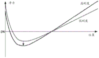
传统的观点是生产一种泵,该泵在对象的典型流量(通常对应于每分钟约5至6升的流量)下具有最佳的工作效率,从而将泵的能耗降至最低。另外,典型的是设计对预载具有相对较低的流量敏感性的泵,如在US-7,435,059中所述,使得所述泵表现出限流特性,以保护所述生理系统免受有害的流量或压力的伤害。The conventional wisdom is to produce a pump that works optimally at the object's typical flow rate (which typically corresponds to a flow rate of about 5 to 6 liters per minute), thereby minimizing the pump's energy consumption. Additionally, it is typical to design pumps with relatively low flow sensitivity to preload, as described in US-7,435,059, such that the pump exhibits flow limiting characteristics to protect the physiological system from detrimental flow or stress injury.
这种配置会导致对于给定的叶轮转速,心脏泵具有陡峭的泵曲线,该曲线是流速相对于整个泵的扬程压力(入口压力与出口压力之间的差)的曲线图。这表明,为了引起通过所述泵的流量变化,需要大的压力变化,从而提供前述限流特性。This configuration results in a heart pump having a steep pump curve, which is a plot of flow rate versus head pressure (difference between inlet and outlet pressure) across the pump, for a given impeller speed. This shows that in order to cause a change in flow through the pump, a large pressure change is required to provide the aforementioned flow restriction characteristics.
在这种配置中,可能有必要改变所述叶轮的转速和/或轴向位置,从而控制泵的流出,以解决对象循环系统内压力的变化。然而,这种控制系统需要关于所述对象的生理状态的信息,例如血压或流速,以便正确地起作用。这要求使用复杂的传感技术和/或植入的传感器,这是不希望的,并且在许多情况下,至少要对某些参数(例如血液粘度)作出假设,这意味着它们可能不准确。作为结果,许多现有的心脏泵只能承受有限的生理变化,这意味着对象通常在其能够进行的活动方面受到限制。In this configuration, it may be necessary to vary the rotational speed and/or axial position of the impeller to control the outflow of the pump to account for changes in pressure within the subject circulation system. However, such control systems require information about the subject's physiological state, such as blood pressure or flow rate, in order to function properly. This requires the use of complex sensing techniques and/or implanted sensors, which is undesirable, and in many cases makes assumptions about at least some parameters (eg blood viscosity), which means they may be inaccurate. As a result, many existing heart pumps can only withstand limited physiological changes, which means that subjects are often limited in the activities they can perform.
发明内容SUMMARY OF THE INVENTION
在一个广义形式中,本发明的一个方面试图提供一种心脏泵,其包含:限定腔体的外壳,腔体包含:至少一个与腔体的轴线对准的入口;以及,至少一个被设置在所述腔体的圆周外壁中的出口;叶轮,设置在腔体内,所述叶轮包含转子和安装在转子上用于将流体从进口径向向外推动到出口的叶片;驱动器,用于在所述腔体中旋转所述叶轮,所述驱动器包含:多个周向间隔开的永久驱动器磁体,其被安装在所述转子的第一面内并紧邻转子的第一面;以及,多个周向间隔开的驱动器线圈,其被安装在所述外壳内,紧邻所述腔体的第一端,每个线圈缠绕在驱动器定子的相应的驱动器定子极上,并且与所述驱动器磁体基本径向对准,所述驱动器线圈被配置为产生与所述驱动器磁体协作的驱动器磁场,从而使所述叶轮旋转;以及,磁性轴承,包含:第一和第二环形磁性轴承构件,安装在所述转子的第二面内并紧邻所述转子的第二面,所述第一磁性轴承构件被设置在所述第二磁性轴承构件的径向外侧;多个沿周向间隔开的基本为U形的轴承定子,其被安装在所述外壳中紧邻所述腔体的第二端的位置,每个U形的轴承定子具有第一和第二轴承定子腿,它们分别与所述第一和第二磁性轴承构件相互作用;以及,在每个轴承定子上的至少一个轴承线圈,产生与所述磁性轴承构件协作的磁场,从而实现以下操作中至少之一:控制所述叶轮的轴向位置;以及,至少部分限制所述叶轮的径向运动。In one broad form, one aspect of the present invention seeks to provide a heart pump comprising: a housing defining a cavity, the cavity comprising: at least one inlet aligned with an axis of the cavity; and, at least one disposed in an outlet in the peripheral outer wall of the cavity; an impeller, disposed within the cavity, the impeller comprising a rotor and blades mounted on the rotor for urging fluid radially outward from the inlet to the outlet; a driver for use in the rotating the impeller in the cavity, the driver comprising: a plurality of circumferentially spaced permanent driver magnets mounted within and proximate a first face of the rotor; and a plurality of circumferentially spaced permanent driver magnets spaced-apart driver coils mounted within the housing proximate the first end of the cavity, each coil wound on a corresponding driver stator pole of the driver stator and substantially radial to the driver magnet aligned, the driver coil is configured to generate a driver magnetic field that cooperates with the driver magnet to rotate the impeller; and a magnetic bearing comprising: first and second annular magnetic bearing members mounted on the rotor In the second face of and immediately adjacent to the second face of the rotor, the first magnetic bearing member is disposed radially outward of the second magnetic bearing member; a plurality of circumferentially spaced substantially U-shaped bearing stators mounted in the housing proximate the second end of the cavity, each U-shaped bearing stator having first and second bearing stator legs, which are magnetically coupled to the first and second, respectively bearing members interacting; and, at least one bearing coil on each bearing stator, generating a magnetic field that cooperates with the magnetic bearing members to achieve at least one of: controlling the axial position of the impeller; and, Radial movement of the impeller is at least partially restricted.
在一个实施例中:所述第一和第二轴承定子腿分别与所述第一和第二磁性轴承构件基本磁对准;所述第一和第二轴承定子腿分别与所述第一和第二磁性轴承构件基本径向对准;所述第一和第二轴承定子分别与所述第一和第二磁性轴承构件配合,从而当所述轴承定子腿与所述磁性轴承构件基本对准时,来自单个轴承的径向力约为0N-2N;所述第一和第二轴承定子腿中至少一个相对于第一和第二磁性轴承构件中的对应的一个径向偏移一段距离,该距离为下面至少之一:少于1mm;少于0.5mm;以及,少于0.2mm。In one embodiment: the first and second bearing stator legs are substantially magnetically aligned with the first and second magnetic bearing members, respectively; the first and second bearing stator legs are The second magnetic bearing members are substantially radially aligned; the first and second bearing stators mate with the first and second magnetic bearing members, respectively, such that when the bearing stator legs are substantially aligned with the magnetic bearing members , the radial force from a single bearing is about 0N-2N; at least one of the first and second bearing stator legs is radially offset by a distance relative to a corresponding one of the first and second magnetic bearing members, the The distance is at least one of: less than 1 mm; less than 0.5 mm; and, less than 0.2 mm.
在一个实施例中,所述驱动器定子包含软磁复合芯,该软磁复合芯包含从环形驱动器定子轭沿轴向方向延伸的多个驱动器定子极。In one embodiment, the driver stator comprises a soft magnetic composite core comprising a plurality of driver stator poles extending in an axial direction from the annular driver stator yoke.
在一个实施例中,所述驱动器定子轭的厚度至少为以下之一:在1mm至2.5mm之间;约1.75mm。In one embodiment, the thickness of the driver stator yoke is at least one of: between 1 mm and 2.5 mm; about 1.75 mm.
在一个实施例中,所述驱动器定子极是以下至少之一:楔形;三角形;以及,梯形。In one embodiment, the driver stator pole is at least one of: wedge-shaped; triangular; and trapezoidal.
在一个实施例中,相邻的驱动器定子极由槽隔开,该槽中至少有一个:至少下列之一的宽度:在4mm至7.4mm之间;约6mm;以及,至少下列之一的深度:在4mm至14mm之间;约11.25mm。In one embodiment, adjacent driver stator poles are separated by slots, at least one of the slots: a width of at least one of: between 4 mm and 7.4 mm; about 6 mm; and a depth of at least one of : Between 4mm and 14mm; approximately 11.25mm.
在一个实施例中,所述驱动器定子具有以下至少之一:至少为如下之一的内半径:在14mm至18mm之间;以及,约16mm;以及,至少为如下之一的外半径:在22mm至25mm之间;以及,约24.5mm。In one embodiment, the driver stator has at least one of: an inner radius of at least one of: between 14 mm and 18 mm; and, about 16 mm; and, an outer radius of at least one of: at 22 mm between 25mm; and, approximately 24.5mm.
在一个实施例中,每个驱动器磁体为如下至少之一:如下至少一个的相交角度:在15°至36°之间;以及,约25°;以及,厚度至少为以下之一:在0.8mm至3mm之间;约2.6mm。In one embodiment, each driver magnet is at least one of: an angle of intersection of at least one of: between 15° and 36°; and, about 25°; and, having a thickness of at least one of: at 0.8 mm to 3mm; about 2.6mm.
在一个实施例中,每个驱动器磁体都安装在环形转子驱动器轭上。In one embodiment, each driver magnet is mounted on an annular rotor driver yoke.
在一个实施例中,心脏泵包含形成转子驱动器轭和转子轴承轭的公共轭。In one embodiment, the heart pump includes a common yoke forming the rotor drive yoke and the rotor bearing yoke.
在一个实施例中,所述转子驱动器轭厚度至少为以下之一:在1mm至5mm之间;以及,在1.5mm至2.5mm之间;以及,约1.9mm。In one embodiment, the rotor drive yoke thickness is at least one of: between 1 mm and 5 mm; and, between 1.5 mm and 2.5 mm; and, about 1.9 mm.
在一个实施例中:驱动器磁体的数量至少为以下之一:8;10;14;以及,16;以及,定子极数至少为以下之一:12;15;以及,18。In one embodiment: the number of driver magnets is at least one of: 8; 10; 14; and, 16; and, the number of stator poles is at least one of: 12;
在一个实施例中,所述驱动器包含12个定子极,被构成为以下至少一项:一个三相马达;以及,两个三相马达。In one embodiment, the drive includes 12 stator poles configured as at least one of: a three-phase motor; and, two three-phase motors.
在一个实施例中,所述驱动器包含使用三角形配置和星形配置中的至少一种连接的多个线圈。In one embodiment, the driver includes a plurality of coils connected using at least one of a delta configuration and a star configuration.
在一个实施例中,所述驱动器和转子配置成使得以下至少一项:所述转子的所述第一面与所述腔体的所述第一端之间的间隔为以下至少之一:在使用中,2mm至5mm之间;在使用中,2mm至3mm之间;以及,在使用中,大约2.3mm;驱动器定子极面和驱动器磁体面之间的间隔至少为以下之一:在使用中,2.5mm至6mm之间;在使用中,2.5mm至4mm之间;以及,在使用中,大约3.2mm;驱动器定子磁轭和驱动器磁轭之间的间隔至少为以下之一:在使用中,7mm至25mm之间;在使用中,8mm至20mm之间;以及,在使用中,大约17mm;以及,驱动器定子极面与驱动器磁轭之间的间隔至少为以下之一:在使用中,4mm至8mm之间;在使用中,4.5mm至7mm之间;以及,在使用中,大约5.8mm。In one embodiment, the driver and rotor are configured such that at least one of the following: the separation between the first face of the rotor and the first end of the cavity is at least one of: In use, between 2mm and 5mm; in use, between 2mm and 3mm; and, in use, approximately 2.3mm; the spacing between the driver stator pole face and the driver magnet face is at least one of the following: in use , between 2.5mm and 6mm; in use, between 2.5mm and 4mm; and, in use, about 3.2mm; the spacing between the driver stator yoke and the driver yoke is at least one of the following: in use , between 7mm and 25mm; in use, between 8mm and 20mm; and, in use, about 17mm; and, the spacing between the driver stator pole faces and the driver yoke is at least one of the following: in use, Between 4mm and 8mm; in use, between 4.5mm and 7mm; and, in use, about 5.8mm.
在一个实施例中,所述转子的所述第一面与所述腔体的所述第一端之间的间隔为以下至少之一:在使用中,至少2.3mm;以及,在使用中,足以容纳所述叶轮的轴向运动。In one embodiment, the separation between the first face of the rotor and the first end of the cavity is at least one of: in use, at least 2.3 mm; and, in use, Sufficient to accommodate axial movement of the impeller.
在一个实施例中,所述叶片安装所述转子的所述第一面上且在所述转子的所述第一面与所述腔体的所述第一端之间,并且其中所述叶片的高度至少为以下之一:在1.5mm至5mm之间;在1.5mm至2.5mm之间;在1.8mm至2.2mm之间;约2mm。In one embodiment, the vane is mounted on the first face of the rotor between the first face of the rotor and the first end of the cavity, and wherein the vane The height is at least one of the following: between 1.5mm and 5mm; between 1.5mm and 2.5mm; between 1.8mm and 2.2mm; about 2mm.
在一个实施例中,每个轴承定子腿至少有一个:至少下列之一的宽度:在2mm至4mm之间;所述第一轴承定子腿约3.6mm;以及,所述第二轴承定子腿约2.9mm;以及,长度至少为如下之一:在5mm至35mm之间;以及,约14.8mm。In one embodiment, each bearing stator leg has at least one: a width of at least one of: between 2 mm and 4 mm; the first bearing stator leg is about 3.6 mm; and the second bearing stator leg is about 3.6 mm 2.9mm; and, a length of at least one of: between 5mm and 35mm; and, about 14.8mm.
在一个实施例中,所述至少一个轴承线圈被缠绕在所述第一轴承定子腿上。In one embodiment, the at least one bearing coil is wound on the first bearing stator leg.
在一个实施例中,至少一个轴承定子腿至少在所述轴承定子腿的一端附近比相应的磁性轴承构件窄。In one embodiment, at least one bearing stator leg is narrower than the corresponding magnetic bearing member at least near one end of said bearing stator leg.
在一个实施例中,至少一个轴承定子腿靠近所述轴承定子腿的一端向内渐缩。In one embodiment, at least one bearing stator leg tapers inwardly proximate an end of said bearing stator leg.
在一个实施例中,所述渐缩部至少具有以下之一:至少如下之一的高度:在0mm至10mm之间;以及,约5mm;至少如下之一的宽度:在0mm至4mm之间;以及,在0.5mm至2mm之间。In one embodiment, the tapered portion has at least one of: a height of at least one of: between 0 mm and 10 mm; and, about 5 mm; a width of at least one of: between 0 mm and 4 mm; And, between 0.5mm and 2mm.
在一个实施例中,所述渐缩部被构造成以下至少之一:朝向磁性轴承构件的中心线;以及,使得当所述转子从中心径向位置径向偏移时,来自单个轴承的径向回复力增加。In one embodiment, the tapered portion is configured to at least one of: towards the centerline of the magnetic bearing member; and, such that when the rotor is radially offset from the center radial position, the diameter from a single bearing Increase in resilience.
在一个实施例中,所述第一和第二磁性轴承构件中的至少一个包含环形永久轴承磁体。In one embodiment, at least one of the first and second magnetic bearing members comprises annular permanent bearing magnets.
在一个实施例中,所述第一和第二磁性轴承构件中的至少一个包含环形铁构件。In one embodiment, at least one of the first and second magnetic bearing members comprises an annular iron member.
在一个实施例中,第一和第二磁性轴承构件中的至少一个具有以下至少之一:厚度至少为以下之一:在1mm至3mm之间;以及,约2.4mm;以及,宽度至少为以下之一:在3mm至4.5mm之间;约2.5mm;以及,约3.5mm。In one embodiment, at least one of the first and second magnetic bearing members has at least one of: a thickness of at least one of: between 1 mm and 3 mm; and, about 2.4 mm; and, a width at least of One of: between 3mm and 4.5mm; about 2.5mm; and, about 3.5mm.
在一个实施例中,所述第一和第二磁性轴承构件被设置在共同的环形叠片或实心铁轴承转子轭上。In one embodiment, the first and second magnetic bearing members are provided on a common annular lamination or solid iron bearing rotor yoke.
在一个实施例中,所述轴承转子轭至少具有以下一项:宽度至少为以下之一:在10mm至13mm之间;以及,约11mm;以及,厚度至少为以下之一:在1mm至5mm之间;以及,在1.5mm至2.5mm之间;以及,约1.9mm。In one embodiment, the bearing rotor yoke has at least one of: a width of at least one of: between 10 mm and 13 mm; and, about 11 mm; and, a thickness of at least one of: between 1 mm and 5 mm and, between 1.5mm and 2.5mm; and, about 1.9mm.
在一个实施例中,所述第一和第二磁性轴承构件中的至少一个朝向所述第二转子面向内渐缩。In one embodiment, at least one of the first and second magnetic bearing members tapers inwardly towards the second rotor surface.
在一个实施例中,所述渐缩部至少是以下之一:朝向磁性轴承构件的中心线;以及,使得当所述转子从中心径向位置径向偏移时,来自单个轴承的径向回复力增加。In one embodiment, the tapered portion is at least one of: towards the centerline of the magnetic bearing member; and such that when the rotor is radially offset from the center radial position, radial recovery from a single bearing force increases.
在一个实施例中,所述第一和第二磁性轴承构件中的至少一个包含渐缩铁靴。In one embodiment, at least one of the first and second magnetic bearing members includes a tapered shoe.
在一个实施例中,所述第二轴承定子腿是渐缩的,并且所述第二磁性轴承构件包含永磁体。In one embodiment, the second bearing stator leg is tapered and the second magnetic bearing member contains permanent magnets.
在一个实施例中,所述第一轴承定子腿基本上没有渐缩,并且所述第一轴承磁性构件是环形铁构件。In one embodiment, the first bearing stator leg is substantially untapered, and the first bearing magnetic member is an annular ferrous member.
在一个实施例中,所述第一轴承定子腿是渐缩的,并且所述第一轴承磁性构件是环形的永磁体。In one embodiment, the first bearing stator leg is tapered and the first bearing magnetic member is an annular permanent magnet.
在一个实施例中,心脏泵提供至少部分左心室功能。In one embodiment, the heart pump provides at least a portion of left ventricular function.
在一个实施例中,心脏泵提供至少部分右心室功能。In one embodiment, the heart pump provides at least a portion of right ventricular function.
在一个实施例中,所述叶轮包含设置在转子主体上的第一和第二组叶片,所述转子被设置在所述腔体内以限定:第一腔体部分,第一腔体部分具有第一入口和第一出口,所述第一组叶片被设置在所述第一腔体部分内,以限定提供至少部分左心室功能的第一泵;以及,第二腔体部分,具有第二入口和第二出口,所述第二组叶片被设置在所述第二腔体部分内,以限定第二泵,所述第二泵提供至少部分右心室功能。In one embodiment, the impeller includes first and second sets of vanes disposed on a rotor body, the rotor being disposed within the cavity to define: a first cavity portion having a first cavity portion an inlet and a first outlet, the first set of vanes disposed within the first cavity portion to define a first pump providing at least a portion of left ventricular function; and a second cavity portion having a second inlet and a second outlet, the second set of vanes are disposed within the second cavity portion to define a second pump that provides at least a portion of right ventricular function.
在一个实施例中,心脏泵是完全的人造心脏。In one embodiment, the heart pump is a complete artificial heart.
在一个实施例中,所述叶轮的所述轴向位置决定了每组叶片与对应的腔体表面之间的间距,所述间距用于控制所述流体从所述入口到所述出口的流体流动。In one embodiment, the axial position of the impeller determines the spacing between each set of vanes and the corresponding cavity surface, the spacing being used to control the flow of the fluid from the inlet to the outlet flow.
在一个实施例中,在所述磁性轴承失效的情况下,所述叶轮和外壳共同定义流体动力轴承。In one embodiment, the impeller and housing together define a hydrodynamic bearing in the event of failure of the magnetic bearing.
在一个实施例中,所述流体动力轴承至少部分地由所述叶轮的至少一些所述叶片的上表面限定。In one embodiment, the hydrodynamic bearing is at least partially defined by the upper surfaces of at least some of the blades of the impeller.
在一个实施例中,所述流体动力轴承由所述叶轮的叶片的面向所述腔体的所述第一端的上表面限定。In one embodiment, the hydrodynamic bearing is defined by the upper surface of the vanes of the impeller facing the first end of the cavity.
在一个实施例中,所述上表面包含前斜坡和后平垫。In one embodiment, the upper surface includes a front ramp and a rear flat pad.
在一个实施例中,至少如下之一:所述平垫的内半径至少为以下之一:在16mm至22mm之间;以及,在18mm至20mm之间;所述平垫的长度至少为以下之一:在1mm至5mm之间;在2mm至4mm之间;以及,约3mm;所述斜坡的长度至少为如下之一:在5mm至15mm之间;在8mm至12mm之间;以及,约10mm;以及,所述斜坡的高度至少为如下之一:在0.02mm至0.1mm之间;在0.04mm至0.08mm之间;以及,约0.06mm。In one embodiment, at least one of the following: the inner radius of the flat pad is at least one of the following: between 16mm and 22mm; and, between 18mm and 20mm; the length of the flat pad is at least one of the following One: between 1mm and 5mm; between 2mm and 4mm; and, about 3mm; the length of the slope is at least one of the following: between 5mm and 15mm; between 8mm and 12mm; and, about 10mm and, the height of the ramp is at least one of: between 0.02 mm and 0.1 mm; between 0.04 mm and 0.08 mm; and, about 0.06 mm.
在一个实施例中,所述叶片至少如下之一:内半径至少为如下之一:在10mm至20mm之间;在12mm至18mm之间,在14mm至16mm之间;以及,约15mm;外半径至少为以下之一:在20mm至30mm之间;在22mm至28mm之间;在24mm至26mm之间;以及,约25mm。In one embodiment, the blade is at least one of the following: the inner radius is at least one of: between 10mm and 20mm; between 12mm and 18mm, between 14mm and 16mm; and, about 15mm; At least one of: between 20mm and 30mm; between 22mm and 28mm; between 24mm and 26mm; and, about 25mm.
在一个实施例中,心脏泵包含控制器,其用于控制使用中的所述驱动器和轴承的操作。In one embodiment, the heart pump includes a controller for controlling the operation of the driver and bearing in use.
在一个实施例中,所述控制器包含根据存储在存储器中的软件指令进行操作的处理器。In one embodiment, the controller includes a processor operating in accordance with software instructions stored in memory.
在一个实施例中,所述控制器控制驱动器以选择性地产生轴向吸引力。In one embodiment, the controller controls the driver to selectively generate the axial attraction force.
在一个实施例中,所述控制器控制所述驱动器以产生轴向吸引力以便实现以下至少之一:在所述腔体内移动所述叶轮;以及,当在所述磁性轴承失效的情况下使用流体动力轴承运行时提高抗冲击性。In one embodiment, the controller controls the driver to generate an axial attraction force to achieve at least one of: moving the impeller within the cavity; and, when used in the event of a failure of the magnetic bearing Improved shock resistance during hydrodynamic bearing operation.
在一个实施例中,所述控制器:检测如下至少之一:所述磁性轴承的失效;以及,当所述磁性轴承失效时,所述叶轮向所述腔体的所述第二端的移动;以及,响应所述检测,控制所述驱动器以产生所述轴向吸引力。In one embodiment, the controller: detects at least one of: failure of the magnetic bearing; and, when the magnetic bearing fails, movement of the impeller toward the second end of the cavity; And, in response to the detection, the driver is controlled to generate the axial attraction force.
在一个实施例中,所述控制器基于以下至少之一来检测所述磁性轴承的失效:轴承指示器,指示所述磁性轴承所用电流;驱动器指示器,指示所述驱动器使用的电流;以及,传感器信号。In one embodiment, the controller detects the failure of the magnetic bearing based on at least one of: a bearing indicator indicating the current used by the magnetic bearing; a driver indicator indicating the current used by the driver; and, sensor signal.
在一个实施例中,心脏泵的轴向系统刚度至少为如下之一:至少10N/mm;至少20N/mm;至少30N/mm;少于60N/mm;少于50N/mm;约10-60N/mm;约25-50N/mm;约15-25N/mm;约30-40N/mm;以及,约35-40N/mm。In one embodiment, the axial system stiffness of the cardiac pump is at least one of: at least 10 N/mm; at least 20 N/mm; at least 30 N/mm; less than 60 N/mm; less than 50 N/mm; about 10-60 N /mm; about 25-50 N/mm; about 15-25 N/mm; about 30-40 N/mm; and, about 35-40 N/mm.
在一个实施例中,心脏泵的径向系统刚度至少为如下之一:在0.5N/mm至11N/mm之间;在0.5N/mm至1.5N/mm之间;在1.5N/mm至3.0N/mm之间;在3N/mm至6N/mm之间;以及,在6N/mm至11N/mm之间。In one embodiment, the radial system stiffness of the cardiac pump is at least one of: between 0.5 N/mm and 11 N/mm; between 0.5 N/mm and 1.5 N/mm; between 1.5 N/mm and Between 3.0 N/mm; between 3 N/mm and 6 N/mm; and, between 6 N/mm and 11 N/mm.
在一个广义形式中,本发明的一个方面试图提供一种心脏泵,其包含:限定腔体的外壳,腔体包含:至少一个与所述腔体的轴线对准的入口;以及,至少一个设置在所述腔体的圆周外壁中的出口;设置在所述腔体内的叶轮,所述叶轮包含转子和安装在所述转子上的叶片,用于将流体从所述入口径向向外推动到所述出口;用于在所述腔体中旋转所述叶轮的驱动器,所述驱动器包含:多个周向隔开的永久驱动器磁体,其安装在所述转子的第一面内并紧邻所述转子的第一面;以及,多个周向间隔开的驱动器线圈,其安装在所述外壳内,紧邻所述腔体的第一端,每个线圈被缠绕在驱动器定子的相应的驱动器定子极上,并且与所述驱动器磁体基本径向对齐,所述驱动器线圈被构成为产生与所述驱动器磁体协作的驱动器磁场,从而使所述叶轮旋转。In one broad form, one aspect of the present invention seeks to provide a heart pump comprising: a housing defining a cavity, the cavity comprising: at least one inlet aligned with an axis of the cavity; and, at least one arrangement an outlet in the peripheral outer wall of the cavity; an impeller disposed within the cavity, the impeller comprising a rotor and vanes mounted on the rotor for urging fluid radially outward from the inlet to the outlet; a driver for rotating the impeller in the cavity, the driver comprising: a plurality of circumferentially spaced permanent driver magnets mounted in the first face of the rotor and proximate the rotor a first face of the rotor; and, a plurality of circumferentially spaced driver coils mounted within the housing proximate the first end of the cavity, each coil being wound around a corresponding driver stator pole of the driver stator On and substantially radially aligned with the driver magnet, the driver coil is configured to generate a driver magnetic field cooperating with the driver magnet to rotate the impeller.
在一个实施例中,心脏泵还包含用于将所述叶轮支承在所述腔体内的轴承,所述轴承至少是以下之一:磁性轴承;流体动力轴承;以及,物理轴承。In one embodiment, the heart pump further includes a bearing for supporting the impeller within the cavity, the bearing being at least one of: a magnetic bearing; a hydrodynamic bearing; and, a physical bearing.
在一个广义形式中,本发明的一个方面试图提供一种心脏泵,其包含:限定腔体的外壳,腔体包含:至少一个与所述腔体的轴线对准的入口;以及,至少一个设置在所述腔体的圆周外壁中的出口;设置在所述腔体内的叶轮,所述叶轮包含转子和安装在所述转子上的叶片,用于将流体从所述入口径向向外推动到所述出口;以及,磁性轴承,包含:安装在所述转子的第二面内并紧邻所述转子的第二面的第一和第二环形磁性轴承构件,所述第一磁性构件被设置在所述第二磁性轴承构件的径向外侧;多个沿周向间隔开的基本为U形的轴承定子,其被安装在所述外壳中紧邻所述腔体的第二端的位置,每个U形轴承定子具有分别与所述第一和第二磁性轴承构件相互作用的第一和第二轴承定子腿;以及,在每个轴承定子上的至少一个轴承线圈,其产生磁场,该磁场与所述磁性轴承构件协作,从而至少如下之一:控制所述叶轮的轴向位置;以及,至少部分地限制所述叶轮的径向运动。In one broad form, one aspect of the present invention seeks to provide a heart pump comprising: a housing defining a cavity, the cavity comprising: at least one inlet aligned with an axis of the cavity; and, at least one arrangement an outlet in the peripheral outer wall of the cavity; an impeller disposed within the cavity, the impeller comprising a rotor and vanes mounted on the rotor for urging fluid radially outward from the inlet to the outlet; and, a magnetic bearing comprising: first and second annular magnetic bearing members mounted within and proximate to the second face of the rotor, the first magnetic member being disposed at radially outer side of said second magnetic bearing member; a plurality of circumferentially spaced substantially U-shaped bearing stators mounted in said housing proximate a second end of said cavity, each U A shaped bearing stator having first and second bearing stator legs interacting with the first and second magnetic bearing members, respectively; and at least one bearing coil on each bearing stator that generates a magnetic field that interacts with all of the bearing stators. The magnetic bearing members cooperate to at least one of: control an axial position of the impeller; and at least partially limit radial movement of the impeller.
在一个广义形式中,本发明的一个方面试图提供一种心脏泵,其包含:限定腔体的外壳,腔体包含:至少一个与所述腔体的轴线对准的入口;以及,至少一个设置在所述腔体的圆周外壁中的出口;设置在所述腔体内的叶轮,所述叶轮包含转子和安装在所述转子上的叶片,用于将流体从所述入口径向向外推动到所述出口;驱动器,用于在所述腔体中旋转所述叶轮,所述驱动器包含:多个周向间隔开的永久驱动器磁体,其安装在所述转子的第一面内并紧邻所述转子的第一面;以及,多个在圆周方向上间隔开的驱动器线圈,被安装在所述外壳内,靠近所述腔体的第一端,并且其中,所述叶轮的叶片和所述外壳的所述第一端协作限定流体动力轴承。In one broad form, one aspect of the present invention seeks to provide a heart pump comprising: a housing defining a cavity, the cavity comprising: at least one inlet aligned with an axis of the cavity; and, at least one arrangement an outlet in the peripheral outer wall of the cavity; an impeller disposed within the cavity, the impeller comprising a rotor and vanes mounted on the rotor for urging fluid radially outward from the inlet to the outlet; a driver for rotating the impeller in the cavity, the driver comprising: a plurality of circumferentially spaced permanent driver magnets mounted in a first face of the rotor and proximate the rotor a first face of the rotor; and a plurality of circumferentially spaced driver coils mounted within the housing proximate the first end of the cavity, and wherein the vanes of the impeller and the housing The first ends of the cooperatively define a hydrodynamic bearing.
在一个实施例中,所述流体动力轴承由面向所述腔体的所述第一端的所述叶轮的所述叶片的上表面限定。In one embodiment, the hydrodynamic bearing is defined by an upper surface of the vanes of the impeller facing the first end of the cavity.
在一个实施例中,所述上表面包含前斜坡和后平垫。In one embodiment, the upper surface includes a front ramp and a rear flat pad.
在一个实施例中,如下至少之一:所述平垫的内半径至少为以下之一:在16mm至22mm之间;以及,在18mm至20mm之间;所述平垫的长度至少为以下之一:在1mm至5mm之间;在2mm至4mm之间;以及,约3mm;所述斜坡的长度至少为如下之一:在5mm至15mm之间;在8mm至12mm之间;以及,约10mm;以及,所述斜坡的高度至少为如下之一:在0.02mm至0.1mm之间;在0.04mm至0.08mm之间;以及,约0.06mm。In one embodiment, at least one of the following: the inner radius of the flat pad is at least one of the following: between 16mm and 22mm; and, between 18mm and 20mm; the length of the flat pad is at least one of the following One: between 1mm and 5mm; between 2mm and 4mm; and, about 3mm; the length of the slope is at least one of the following: between 5mm and 15mm; between 8mm and 12mm; and, about 10mm and, the height of the ramp is at least one of: between 0.02 mm and 0.1 mm; between 0.04 mm and 0.08 mm; and, about 0.06 mm.
在一个实施例中,所述叶片为如下至少一个:内半径至少为以下之一:在10mm至20mm之间;在12mm至18mm之间,在14mm至16mm之间;以及,约15mm;外半径至少为以下之一:在20mm至30mm之间;在22mm至28mm之间;在24mm至26mm之间;以及,约25mm。In one embodiment, the vanes are at least one of: an inner radius of at least one of: between 10mm and 20mm; between 12mm and 18mm, between 14mm and 16mm; and, about 15mm; an outer radius At least one of: between 20mm and 30mm; between 22mm and 28mm; between 24mm and 26mm; and, about 25mm.
在一个实施例中,心脏泵包含磁性轴承,以实现以下至少一项:控制所述叶轮的轴向位置;至少部分地限制所述叶轮的径向运动中的,并且其中,所述流体动力轴承被构成为在所述磁体轴承失效时运行。In one embodiment, a heart pump includes a magnetic bearing to achieve at least one of: controlling the axial position of the impeller; at least partially limiting radial motion of the impeller, and wherein the hydrodynamic bearing is configured to operate upon failure of the magnet bearing.
在一个实施例中,心脏泵包含控制器,其控制使用中的所述驱动器和轴承的操作。In one embodiment, the heart pump includes a controller that controls the operation of the driver and bearing in use.
在一个实施例中,所述控制器包含根据存储在所述存储器中的软件指令进行操作的处理器。In one embodiment, the controller includes a processor operating in accordance with software instructions stored in the memory.
在一个实施例中,所述控制器控制所述驱动器以选择性地产生轴向吸引力。In one embodiment, the controller controls the driver to selectively generate an axial attraction force.
在一个实施例中,所述控制器控制所述驱动器以产生所述轴向吸引力以便实现以下至少之一:在所述腔体内移动所述叶轮;以及,当在所述磁性轴承失效的情况下使用流体动力轴承运行时,增加抗冲击性。In one embodiment, the controller controls the driver to generate the axial attraction force to achieve at least one of: moving the impeller within the cavity; and, in the event of failure of the magnetic bearing Increased shock resistance when running under hydrodynamic bearings.
在一个实施例中,所述控制器:检测以下至少之一:磁性轴承的失效;以及,当所述磁性轴承失效时,所述叶轮向所述腔体的第二端的移动;以及,响应于所述检测,控制所述驱动器以产生所述轴向吸引力。In one embodiment, the controller: detects at least one of: failure of a magnetic bearing; and, when the magnetic bearing fails, movement of the impeller toward the second end of the cavity; and, in response to The detection controls the driver to generate the axial attraction force.
在一个实施例中,所述控制器基于以下至少之一来检测所述磁性轴承的失效:指示所述磁性轴承所使用的电流的轴承指示器;指示所述驱动器使用的电流的动器指示器;以及,传感器信号。In one embodiment, the controller detects the failure of the magnetic bearing based on at least one of: a bearing indicator indicating current used by the magnetic bearing; an actuator indicator indicating current used by the driver ; and, the sensor signal.
应当理解,本发明的广义形式及其各自的特征可以结合和/或独立地使用,并且在不旨在限制本发明的情况下,引用单独的广义形式。It should be understood that the broad forms of the invention and their respective features may be used in combination and/or independently, and reference to separate broad forms is not intended to limit the invention.
附图说明Description of drawings
现在将参考附图描述本发明的各种示例和实施例,其中:Various examples and embodiments of the present invention will now be described with reference to the accompanying drawings, in which:
图1A是心脏泵的示例的示意性立体图;1A is a schematic perspective view of an example of a heart pump;
图1B是图1A的心脏泵的示意性剖视图;FIG. 1B is a schematic cross-sectional view of the heart pump of FIG. 1A;
图1C是图1A的心脏泵的示意性分解立体图;1C is a schematic exploded perspective view of the heart pump of FIG. 1A;
图1D是图1A的心脏泵的控制系统的示例的示意图;1D is a schematic diagram of an example of a control system for the heart pump of FIG. 1A;
图2A是驱动器磁体配置的示例的示意性俯视侧视立体图;2A is a schematic top side perspective view of an example of a driver magnet configuration;
图2B是图2A的驱动器磁体配置的平面示意图;2B is a schematic plan view of the driver magnet configuration of FIG. 2A;
图2C是图2A的驱动器磁体配置的示意性侧视图;Figure 2C is a schematic side view of the driver magnet configuration of Figure 2A;
图2D是轴承磁体配置的示意性俯视侧视立体图;2D is a schematic top side perspective view of a bearing magnet configuration;
图2E是图2D的轴承磁体配置的示意性仰视图;Figure 2E is a schematic bottom view of the bearing magnet configuration of Figure 2D;
图2F是图2D的轴承磁体配置的示意性侧视图;Figure 2F is a schematic side view of the bearing magnet configuration of Figure 2D;
图2G是图2D的带有涡流传感器的轴承磁体装置的示意性仰视图;Figure 2G is a schematic bottom view of the bearing magnet arrangement with eddy current sensor of Figure 2D;
图2H是图2A和2D的轴承和驱动器磁体配置以及涡流传感器的示意性俯视侧视立体图;2H is a schematic top side perspective view of the bearing and driver magnet arrangement and eddy current sensor of FIGS. 2A and 2D;
图2I是图2H的配置的示意性立体剖视图;Figure 2I is a schematic perspective cross-sectional view of the configuration of Figure 2H;
图3A是从左侧泵侧看示例叶轮的示意性立体图;3A is a schematic perspective view of an example impeller from the left side of the pump;
图3B是图3A的叶轮的剖视示意图;3B is a schematic cross-sectional view of the impeller of FIG. 3A;
图3C是图3A的叶轮的示意性立体剖视图;Figure 3C is a schematic perspective cross-sectional view of the impeller of Figure 3A;
图3D是图3A的叶轮从泵的右侧看的示意性立体图;Fig. 3D is a schematic perspective view of the impeller of Fig. 3A from the right side of the pump;
图3E是图3A叶轮替代示例的剖视示意图;3E is a schematic cross-sectional view of an alternative example of the impeller of FIG. 3A;
图4A是驱动器示例的示意性立体图,显示了不同的驱动器参数;4A is a schematic perspective view of an example of a driver showing different driver parameters;
图4B是图4A的驱动器的示意性侧视图,说明了其他驱动器参数;Figure 4B is a schematic side view of the driver of Figure 4A illustrating additional driver parameters;
图5A是驱动器示例的示意性俯视图,显示了第一槽宽度;5A is a schematic top view of an example of a driver showing a first slot width;
图5B是驱动器示例的示意性俯视图,显示了第二槽宽度;5B is a schematic top view of an example of a driver showing a second slot width;
图5C是举例说明驱动马达恒定和轴向力随槽宽变化的示例的曲线图;5C is a graph illustrating an example of a drive motor constant and axial force as a function of slot width;
图6A是驱动器示例的示意性俯视图,显示了第一定子内半径和第一槽宽;6A is a schematic top view of an example of a driver showing a first inner stator radius and a first slot width;
图6B是驱动器示例的示意性俯视图,显示了第二定子内半径和第二槽宽;6B is a schematic top view of an example of a driver showing a second inner stator radius and a second slot width;
图6C是举例说明了随着定子内半径的变化,驱动马达的恒定和轴向力的示例的曲线图;6C is a graph illustrating an example of constant and axial force of a drive motor as a function of stator inner radius;
图6D是说明了具有不同绕组配置的不同速度和转矩极限的示例的曲线图;6D is a graph illustrating an example of different speed and torque limits with different winding configurations;
图7A是示出了用于第一驱动器磁体角度的磁驱动通量的示例的示意性侧视图;7A is a schematic side view showing an example of magnetic drive flux for a first driver magnet angle;
图7B是示出了用于第二驱动器磁体角度的磁驱动磁通量的示例的示意性俯视图;7B is a schematic top view illustrating an example of magnetic drive flux for a second driver magnet angle;
图7C是示出了随驱动器磁体角度变化而变化的驱动轴向力的示例的曲线图;7C is a graph showing an example of drive axial force as a function of driver magnet angle;
图7D是示出了随驱动器磁体角度和厚度变化而变化的驱动马达恒定和轴向力的示例的曲线图;7D is a graph showing an example of drive motor constant and axial force as a function of drive magnet angle and thickness;
图8A是示出了用于第一驱动器定子槽深度的磁驱动通量的示例的示意性侧视图;8A is a schematic side view showing an example of magnetic drive flux for a first driver stator slot depth;
图8B是示出了用于第二个驱动器定子槽深度的磁驱动通量的示例的示意俯视图;8B is a schematic top view showing an example of magnetic drive flux for a second driver stator slot depth;
图8C是示出了随驱动器定子槽深度变化而变化的驱动轴向力的示例的曲线图;8C is a graph showing an example of drive axial force as a function of driver stator slot depth;
图8D是表示不同叶轮左叶片高度的左侧泵曲线示例的曲线图;8D is a graph showing examples of left pump curves for different impeller left blade heights;
图8E是表示不同气隙的驱动轴向力和马达常数的示例的曲线图;8E is a graph representing an example of drive axial force and motor constant for different air gaps;
图8F是特定首选驱动器参数的示意图;Figure 8F is a schematic diagram of specific preferred driver parameters;
图9A是表示不同叶轮轴向位置的轴向驱动力和轴承力变化的曲线图;Figure 9A is a graph showing changes in axial driving force and bearing force for different impeller axial positions;
图9B是表示不同叶轮轴向位置的净轴向力变化的曲线图;Figure 9B is a graph showing the change in net axial force for different impeller axial positions;
图9C是表示不同叶轮径向位置的净径向力变化的曲线图;FIG. 9C is a graph showing the change in net radial force for different impeller radial positions;
图10A和10B是示出了非渐缩的磁性元件在不同径向位置的磁性轴承通量的示意侧视图;10A and 10B are schematic side views showing magnetic bearing flux for non-tapered magnetic elements at different radial positions;
图10C和10D是示出了渐缩的磁性元件的不同径向位置的磁性轴承通量的示意性侧视图;10C and 10D are schematic side views showing magnetic bearing flux for different radial positions of tapered magnetic elements;
图11A和11B是示出包括非渐缩的磁性轴承定子腿的磁性轴承的示例的不同径向位置的磁性轴承通量的示意性侧视图;11A and 11B are schematic side views showing magnetic bearing flux at different radial positions of an example of a magnetic bearing including non-tapered magnetic bearing stator legs;
图11C和11D是示出了包括渐缩的磁性轴承定子腿的磁性轴承的示例的不同径向位置的磁性轴承通量的示意性侧视图;11C and 11D are schematic side views showing magnetic bearing flux at different radial positions of an example of a magnetic bearing including tapered magnetic bearing stator legs;
图12A和12B是示出示例磁性轴承的不同轴向和径向位置的相对轴向力和径向力的曲线图,该示例性磁性轴承包括具有匹配的径向刚度和气隙的渐缩的和无渐缩的定子腿;12A and 12B are graphs showing relative axial and radial forces for different axial and radial positions of an example magnetic bearing including tapered and non-tapered stator legs;
图12C和12D是示出示例磁性轴承的不同轴向和径向位置的相对轴向力和径向力的曲线图,该示例性磁性轴承包括具有匹配的轴向力的渐缩的和无渐缩的定子腿;12C and 12D are graphs showing relative axial and radial forces for different axial and radial positions of an example magnetic bearing including tapered and non-graded with matching axial forces retracted stator legs;
图13是示出了不同的轴承定子腿渐缩量下的刚度比的变化的曲线图;Figure 13 is a graph showing the change in stiffness ratio for different amounts of bearing stator leg taper;
图14是示出了用于包括极靴的磁性轴承的磁性轴承通量的示意性侧视图;14 is a schematic side view showing magnetic bearing flux for a magnetic bearing including pole pieces;
图15A至15F是轴承配置不同示例的示意性侧视图;15A to 15F are schematic side views of different examples of bearing arrangements;
图16A是说明了不同的轴承参数的轴承示例的示意性侧视图;16A is a schematic side view of an example bearing illustrating different bearing parameters;
图16B是图16A的轴承的一部分的示意性特写侧视图,示出了进一步的轴承参数;Figure 16B is a schematic close-up side view of a portion of the bearing of Figure 16A showing further bearing parameters;
图17A是单个VAD心脏泵的示例的示意性立体图;17A is a schematic perspective view of an example of a single VAD heart pump;
图17B是图17A的心脏泵的示意性剖面侧视图;Figure 17B is a schematic cross-sectional side view of the heart pump of Figure 17A;
图17C是图17A的心脏泵的示意性剖面俯视图;Figure 17C is a schematic cross-sectional top view of the heart pump of Figure 17A;
图17D是图17A的心脏泵的叶轮的示意性立体图;Figure 17D is a schematic perspective view of the impeller of the heart pump of Figure 17A;
图17E是图17A的心脏泵的磁性轴承的示意性立体图;Figure 17E is a schematic perspective view of the magnetic bearing of the heart pump of Figure 17A;
图17F是图17A的叶轮的示意性剖视立体图;Figure 17F is a schematic cross-sectional perspective view of the impeller of Figure 17A;
图18A是叶轮处于被动平衡位置时的叶轮腔体的示意图;18A is a schematic view of the impeller cavity when the impeller is in a passively balanced position;
图18B是叶轮处于工作位置时的叶轮腔体的示意图;Figure 18B is a schematic view of the impeller cavity when the impeller is in the working position;
图18C是叶轮腔体的示意图,其中叶轮处于备用流体动力轴承位置;Figure 18C is a schematic view of the impeller cavity with the impeller in the standby hydrodynamic bearing position;
图19A是提供流体动力轴承的叶轮构造的示意性俯视图;19A is a schematic top view of an impeller configuration providing a hydrodynamic bearing;
图19B是图19A的叶轮的叶轮叶片之一的示意性侧视图;Figure 19B is a schematic side view of one of the impeller blades of the impeller of Figure 19A;
图19C是示出轴承参数的示意性俯视图;Figure 19C is a schematic top view showing bearing parameters;
图19D是示出右侧泵性能示例的曲线图;Figure 19D is a graph showing an example of the performance of the right side pump;
图19E示出右侧泵性能示例的图;Figure 19E shows a graph of an example of the performance of the right side pump;
图20A是示出由流体动力轴承产生的有效液压轴向叶轮力的示例的曲线图;20A is a graph showing an example of effective hydraulic axial impeller force generated by a hydrodynamic bearing;
图20B是示出液压和磁体轴向叶轮力示例的图;20B is a graph showing an example of hydraulic and magnet axial impeller forces;
图21A是示出驱动器产生旋转叶轮转矩的操作的示例的示意图;FIG. 21A is a schematic diagram illustrating an example of the operation of the drive to generate torque of the rotating impeller;
图21B是示出驱动器产生负轴向叶轮力的操作的示例的示意图;21B is a schematic diagram illustrating an example of the operation of the driver to generate negative axial impeller force;
图21C是示出驱动器产生正轴向叶轮力的操作的示例的示意图;21C is a schematic diagram illustrating an example of the operation of the driver to generate a positive axial impeller force;
图22A是示出悬浮故障序列期间的磁性轴承目标电流的示例的曲线图;22A is a graph showing an example of a magnetic bearing target current during a suspension fault sequence;
图22B是示出在悬浮故障序列期间的磁性轴承目标位置的示例的曲线图;22B is a graph showing an example of a magnetic bearing target position during a levitation failure sequence;
图22C是表示悬浮故障序列期间驱动器速度的示例的曲线图;22C is a graph representing an example of driver speed during a suspension fault sequence;
图22D是表示悬浮故障时的驱动器目标电流的一例的曲线图;22D is a graph showing an example of a driver target current during a floating fault;
图23是显示正轴向力对净轴向叶轮力的影响的示例的曲线图;23 is a graph showing an example of the effect of positive axial force on net axial impeller force;
图24A是表示轴向刚度对净轴向叶轮力影响的示例的曲线图;24A is a graph showing an example of the effect of axial stiffness on net axial impeller force;
图24B是表示壳体偏移时的轴向叶轮净力变化的一例的曲线图;24B is a graph showing an example of the change in the net axial impeller force when the casing is displaced;
图25A是表示轴承电流对径向刚度影响的示例的曲线图;25A is a graph showing an example of the effect of bearing current on radial stiffness;
图25B是表示轴承电流对谐振频率影响的示例的曲线图;FIG. 25B is a graph showing an example of bearing current effect on resonant frequency;
图25C是示出驱动器电流对谐振频率影响的示例的曲线图;25C is a graph showing an example of the effect of driver current on resonant frequency;
图26A是三相驱动器线圈配置的第一示例的示意图;26A is a schematic diagram of a first example of a three-phase driver coil configuration;
图26B是图26A的驱动器线圈配置的驱动器线圈连接示例的示意图;26B is a schematic diagram of an example driver coil connection of the driver coil configuration of FIG. 26A;
图26C是三相驱动器线圈配置的第二示例的示意图;26C is a schematic diagram of a second example of a three-phase driver coil configuration;
图26D是图26C的线圈配置的线圈连接示例的示意图;26D is a schematic diagram of an example of coil connections for the coil configuration of FIG. 26C;
图27A是单三相三角配置的驱动器线圈连接示例的示意图;27A is a schematic diagram of an example of driver coil connections in a single-phase delta configuration;
图27B是双三相三角配置的驱动器线圈连接示例的示意图;27B is a schematic diagram of an example of driver coil connections in a dual three-phase delta configuration;
图27C是单三相星形配置的驱动器线圈连接示例的示意图;27C is a schematic diagram of an example of driver coil connections in a single three-phase star configuration;
图27D是双三相星形配置的驱动器线圈连接示例的示意图;27D is a schematic diagram of an example of driver coil connections in a dual three-phase star configuration;
图28A是示出使用三角驱动器线圈绕组可获得的驱动器转矩和速度的示例的曲线图;28A is a graph showing an example of driver torque and speed obtainable using delta driver coil windings;
图28B是示出使用三角和星形驱动器线圈构造的驱动器转矩和速度的比较示例的曲线图;28B is a graph showing a comparative example of driver torque and speed using delta and wye driver coil configurations;
图29是示出驱动器线圈绕组匝数对驱动器转矩和速度的影响的示例的曲线图;29 is a graph showing an example of the effect of driver coil winding turns on driver torque and speed;
图30A是表示不同线圈配置的驱动器速度和转矩示例的图;以及,Figure 30A is a graph showing examples of drive speed and torque for different coil configurations; and,
图30B是示出健康和故障双三相星形驱动器线圈配置的驱动器速度和转矩示例的图。30B is a graph showing an example of drive speed and torque for healthy and faulty dual three-phase wye drive coil configurations.
具体实施方式Detailed ways
现在将参考图1A至1D,图2A至2I和图3A至3E描述心脏泵的示例。An example of a heart pump will now be described with reference to FIGS. 1A to 1D , FIGS. 2A to 2I and FIGS. 3A to 3E .
在该示例中,心脏泵是双心室装置,其既可以用作心室辅助装置来辅助对象的左、右心室的功能,也可以作为全人工心脏。然而,将理解的是,尽管参考了双心室装置,但这不是必需的,并且可替代地,本文描述的原理可以等同地应用于单个心室辅助装置或任何其他形式的血泵。In this example, the heart pump is a biventricular device that can be used either as a ventricular assist device to assist the function of the subject's left and right ventricles, or as a total artificial heart. It will be appreciated, however, that although reference is made to a biventricular device, this is not required, and alternatively, the principles described herein may be equally applied to a single ventricular assist device or any other form of blood pump.
在该示例中,心脏泵100包括形成腔体的外壳110。外壳可以是任何合适的形式,但是通常包括主体110.1,连接到主体110.1的左右端盖110.2、110.3,以及位于主体110.1和左端盖110.2之间的端板110.4。外壳可以由任何合适的生物相容性材料制成,并且可以由钛、聚合物等制成。In this example, the
外壳110包括两个入口111、113,其分别连接至左心房/肺静脉和右心房/静脉,或左右心室;以及两个出口112、114,其分别连接至主动脉和肺动脉。虽然示出了两个入口和出口,但是应当理解,这是在双心室装置的背景下,并且单个入口和出口可以用于单个心室装置。The
心脏泵100包含设置在腔体内的叶轮120。叶轮120包括转子121,转子121上安装有叶片,用于在叶轮120旋转时将流体从入口推动到出口。在此示例中,由于心脏泵100是双心室装置,叶轮包括两组叶片122,123,每组叶片用于将流体从相应的入口111、113推向相应的出口112、114。在此示例中,转子121定位在腔体内,以将腔体有效地划分为第一腔体部分和第二腔体部分,每个腔体部分具有各自的入口和出口,从而允许它们各自充当各自的泵。The
因此,在当前示例中,叶片122被用于将流体从所述入口111推动到所述出口112,以图1B中所示的方向设置在所述泵的左侧,并被操作为提供左心室功能,同时叶片123将流体从入口113推向出口114,并起到提供右心室功能的作用。在本文中,所述第一和第二腔体部分通常被称为左腔体和右腔体,并与叶轮120一起分别提供左侧泵和右侧泵。应当理解,就此而言,术语左和右是指腔体的预期心室功能,与附图中泵的特定方向相反,其仅用于说明性目的。Thus, in the current example,
如图3A至3E中示出,叶片122,123具有不同的轮廓,为左侧泵和右侧泵提供不同的流动特性,如将在下面更详细地描述。尤其是,在该例子中,左叶片122通常向外张开,朝向转子121的外周边缘变厚,并且以与叶轮旋转方向(如箭头R所示)成一定角度的方式扫过。然而,并非总是如此,例如,对于LVAD,左叶片径向笔直且薄,类似于如下介绍的右叶片。相反,右叶片123通常是笔直的并且具有恒定的厚度,径向地朝向转子的边缘但不相交地径向延伸。在下文中将更详细地描述对这些配置的影响以及叶片122、123和转子121的特定尺寸。As shown in Figures 3A-3E, the
心脏泵100还包含驱动器130和磁性轴承140,驱动器130使叶轮120在所述腔体内旋转,磁性轴承140控制叶轮120在所述腔体内的轴向位置。该设备还包含控制器150和驱动器和轴承信号发生器137、147,该控制器150在使用中联接到传感器160,驱动器和轴承信号发生器137、147又联接到驱动器和轴承130、140的驱动器和轴承线圈131、141。传感器160用于感测叶轮120在所述腔体内的轴向位置,并且可以采用任何适当的形式,如将在下面更详细地描述的那样。The
在使用中,控制器150使用来自传感器160和可选的其他传感器的信号,使用适当的控制算法,可以控制轴承140和可选的驱动器130的运行。尤其是,控制器150适于监测来自位置传感器160和其他传感器的信号,然后通过信号发生器137控制提供给驱动器线圈131的电流,以控制叶轮的旋转,并且通过信号发生器147控制提供给轴承线圈141的电流,以控制叶轮120的轴向位置。因此,叶轮120受到外壳110中的流体压力的作用,该流体压力在叶轮120上产生净液压。作用在叶轮120上的力由磁性轴承补偿,控制器150进行操作以控制提供给轴承中电磁体的电流量,从而保持叶轮120的位置。这样,磁性轴承系统所使用的电流与作用在叶轮120上的力和压力有直接关系。以这种方式,可以通过磁性轴承信号实时检测入口和出口压力的变化。In use, the
控制器150还可以适用于提供速度控制功能,例如根据诸如泵内的流体压力之类的因素来改变叶轮的旋转速度。The
控制器150可以是任何合适的形式,但是通常包含电子处理设备151,可选的存储器152,和用于连接到心脏泵的接口154,它们中的每一个都通过总线155或其他类似的装置互连。电子处理设备可以是能够解释信号并控制驱动器和轴承的任何形式的电子处理设备,例如微处理器、微芯片处理器、逻辑门配置,与执行逻辑相关的固件,例如FPGA(现场可编程门阵列),或任何其他电子设备,系统或装置。The
控制器还可以实现单独的控制功能,例如单独的模块,从而控制轴承和驱动器。The controller can also implement separate control functions, such as separate modules, to control bearings and drives.
可以提供可选的外部接口153,允许与控制器150的交互。在控制器位于主体外部的情况下,其可以包含诸如触摸屏等的I/O设备153,反之,如果位于主体内部,则其通常采用无线通信模块的形式,允许与外部控制设备通信。An optional
如上描述的心脏泵是可以用作双心室辅助设备,向左心室和右心室提供心室辅助或者可以充当整体人工心脏的心脏泵的示例,允许左心室和右心室的功能完全替换。也可以仅对应于左侧或右侧泵提供类似的配置,从而提供左或右心室辅助设备。A heart pump as described above is an example of a heart pump that can be used as a biventricular assist device, providing ventricular assist to the left and right ventricles, or can act as a total artificial heart, allowing complete replacement of the functions of the left and right ventricles. A similar configuration can also be provided for only the left or right pump, thereby providing a left or right ventricular assist device.
现在将描述驱动器和轴承的更多细节。More details of the drive and bearing will now be described.
在一个实施例中,驱动器包含多个周向间隔开的永久驱动器磁体134,该永久驱动器磁体134被安装在转子121的第一面内并邻近该转子的第一面。相邻的驱动器磁体通常具有相反的极性,尽管可以使用其他配置,例如,如果一个驱动器磁体被一分为二并紧挨另一个放置,则可以实现类似的功能。驱动器130还包含多个在腔体的第一端附近安装在外壳110内的周向间隔开的驱动器线圈131,每个线圈131缠绕在驱动器定子芯132的相应的驱动器定子极132.1上,并且基本上与驱动器磁体134径向对齐。In one embodiment, the driver includes a plurality of circumferentially spaced
在使用中,驱动器线圈131被构成为通过施加适当的电流来产生驱动器磁场,该驱动器磁场与驱动器磁体134协作从而在腔体内使叶轮120旋转。In use, the
在图2A至图2C以及图4A至图4B以及图5A和图5B中更详细地示出了具体的示例驱动器磁体配置。在该实施例中,驱动器线圈131和驱动器定子极132.1是楔形的、三角形的或梯形的,沿周向间隔开并从环形驱动器轭132.2轴向延伸,该环形驱动器轭又联接至安装/PCB(印刷电路板)133,从而允许将驱动器定子芯132固定在外壳110内。驱动器定子芯132通常由软的复合铁芯形成,尽管可以使用其他合适的材料。驱动器磁体134是弓形的稀土磁体,其在转子的外周边缘附近并且在转子的面对驱动器线圈131的面附近周向地间隔开,所述驱动器磁体被安装在软铁转子驱动器轭135上。Specific example driver magnet configurations are shown in more detail in FIGS. 2A-2C and 4A-4B and 5A and 5B. In this embodiment, the driver coils 131 and driver stator poles 132.1 are wedge-shaped, triangular or trapezoidal, spaced circumferentially and extending axially from an annular driver yoke 132.2, which in turn is coupled to the mounting/PCB ( printed circuit board) 133, thereby allowing the
在该实施例中,驱动器定子和驱动器线圈限定了12个与转子121中的驱动器磁体134轴向对齐的电磁体,从而最大化了转子121与驱动器130中的磁体之间的磁耦合程度,然而,根据以下描述将显而易见的是,可以使用其他配置。In this embodiment, the driver stator and driver coils define 12 electromagnets that are axially aligned with the
现在转向磁性轴承140,它通常包含第一环形磁性轴承构件144和第二环形磁性轴承构件145,该第一环形磁性轴承构件144和第二环形磁性轴承构件145安装在转子中面向轴承线圈141的面内并邻近该面,第一磁性轴承构件144设置在第二磁性轴承构件145的径向外侧。磁性轴承构件144、145可被安装到在磁性轴承构件144、145之间延伸的转子轴承轭146和/或与转子轴承轭146整体形成。轴承转子轭可由层压铁板制成,以减少轭内的涡流。Turning now to the
如在图3E的示例中进一步示出的,转子驱动器轭135和转子轴承轭146可以由共同的轭135/146形成。As further shown in the example of FIG. 3E , the
多个沿周向间隔开的大致U形的轴承定子142被安装在外壳110中靠近所述腔体的第二端,每个U形的轴承定子142具有分别与第一和第二磁性轴承构件144、145相互作用的第一和第二轴承定子腿142.1、142.2。在每个轴承定子142上至少提供一个轴承线圈141,该线圈产生与磁场轴承部件145、144协作的磁场,从而控制叶轮120的轴向位置并至少部分地限制叶轮120的径向运动。A plurality of circumferentially spaced generally
在一个实施例中,第一和第二轴承定子腿分别与第一和第二磁性轴承构件基本磁性对准和/或在几何上径向对准。可以这样执行,使得第一轴承定子和第二轴承定子分别与第一磁性轴承构件和第二磁性轴承构件配合,从而当轴承定子腿与磁性轴承基本对准时,来自单个轴承的径向力约为0N-2N。虽然对准可以减少交叉耦合,但某些失准可能会有利于对称的径向回复,并会导致径向力随轴向位置发生变化。因此,在一些实施例中,第一轴承定子腿和第二轴承定子腿中的一个或两个都可以相对于第一磁性轴承构件和第二磁性轴承构件中对应的一个径向偏移一小段距离,例如以下至少之一:小于1毫米、小于0.5毫米和小于0.2毫米。In one embodiment, the first and second bearing stator legs are substantially magnetically aligned and/or geometrically radially aligned with the first and second magnetic bearing members, respectively. This can be performed such that the first bearing stator and the second bearing stator mate with the first magnetic bearing member and the second magnetic bearing member, respectively, such that when the bearing stator legs are substantially aligned with the magnetic bearings, the radial force from a single bearing is approximately 0N-2N. While alignment can reduce cross-coupling, some misalignment may favor symmetrical radial recovery and cause radial force to vary with axial position. Thus, in some embodiments, one or both of the first bearing stator leg and the second bearing stator leg may be radially offset by a small amount relative to a corresponding one of the first magnetic bearing member and the second magnetic bearing member A distance, such as at least one of: less than 1 millimeter, less than 0.5 millimeter, and less than 0.2 millimeter.
在一个特定的实施例中,在图2D至2I中更详细地显示,磁性轴承包含三个轴承线圈141,每个线圈被安装在对应U形轴承定子142的第一轴承定子腿142.1上,第二轴承定子腿142.2位于第一轴承定子腿142.1的径向内侧。轴承定子142被安装到轴承定子支承件143上,并在外壳周围沿圆周方向间隔120°,以便第一轴承定子腿142.1和第二轴承定子腿142.2与相应的磁性材料构件144、145对准,从而控制叶轮120的轴向位置。In a particular embodiment, shown in more detail in Figures 2D to 2I, the magnetic bearing contains three bearing
通常,磁性轴承140包含永磁体,其可以是磁性轴承构件144、145的一部分,或者连接到轴承定子腿中的一个或两个。例如,这可以包含沿周向间隔开的第一和第二永久轴承磁体144、145。替代地,磁性轴承构件可以包含铁磁材料部件144和永磁体145,或者仅包含铁磁材料,其中永磁体联接到定子142的定子轴承腿142.1、142.2。Typically, the
驱动器130和磁性轴承140被安装在外壳110的相对端,使得驱动器和轴承130、140靠近转子121的相对表面设置,例如如图1D、图2H和图2I中示出。在当前示例中,驱动器130被安装在左侧泵附近,而轴承140安装在右侧泵附近,虽然可以想到相反的构造。所示的安排具有很多好处。The
首先,当转子以正常工作速度设置在平衡点(在正常流动的条件下,其可以例如大约位于腔体的中心,但是可以更靠近腔体的左侧或右侧)时,驱动器和转子以及轴承和转子之间的固有吸引力可以配置为基本平衡。First, when the rotor is set at the equilibrium point at normal operating speed (under normal flow conditions, it may for example be approximately in the center of the cavity, but may be closer to the left or right of the cavity), the drive and rotor and bearings The inherent attraction between the rotor and the rotor can be configured to be substantially balanced.
例如,可以配置这种配置,以使驱动器130与叶轮120之间,以及磁性轴承140和叶轮120之间的固有的磁力在腔体内的叶轮平衡位置匹配,该平衡位置对应于正常流动条件下叶轮的所需位置。这最小化了将叶轮120保持在腔体内的位置所需的轴承电流,因此减少了操作,尤其是驱动器和轴向定位叶轮所需的功率。For example, this configuration can be configured so that the inherent magnetic forces between the
另外,除了具有磁力平衡之外,驱动器和轴承产生的力还可以配置为提供所需程度的轴向和径向刚度。在这方面,刚度是叶轮120响应于外力而从平衡位置偏转的量度。在一个实施例中,理想的是使径向刚度最大化,以便将叶轮保持在腔体内径向中心并且停止叶轮接触腔体的内周壁。相反,由于叶轮120的轴向位置可用于流量控制,并且尤其是允许对血液动力学参数的变化进行被动和/或主动响应,因此轴向刚度低的情况是优选的。因此,被动磁力可以构成为有助于满足这些要求,如下面将更详细描述的。Additionally, in addition to being magnetically balanced, the forces generated by the drive and bearings can be configured to provide the desired degree of axial and radial stiffness. In this regard, stiffness is a measure of the deflection of the
在BiVAD/TAH应用的情况下,上述配置的另一个好处是,允许较小的右侧泵腔体尺寸容纳更大尺寸的磁性轴承。尤其是,这允许轴承定子和轴承磁体之间的间隙最小化,因为在该间隙中没有叶片(与左侧不同,在左侧驱动器和转子之间的磁性气隙中存在叶片),如在下面更详细地描述。然而,应当理解,这限制了右侧泵的外径,从而限制了在给定转速下可产生的压力,尽管对于右侧泵,鉴于其输出或压力要求比左侧泵低,通常这不是问题。In the case of BiVAD/TAH applications, another benefit of the above configuration is that it allows the smaller right side pump cavity size to accommodate larger size magnetic bearings. In particular, this allows the gap between the bearing stator and the bearing magnet to be minimized, since there are no vanes in this gap (unlike the left, where there are vanes in the magnetic air gap between the drive and rotor on the left), as below described in more detail. It should be understood, however, that this limits the outer diameter of the right side pump and thus the pressure that can be produced at a given RPM, although for the right side pump this is generally not an issue given its lower output or pressure requirements than the left side pump .
现在将描述驱动器和轴承中的每一个的许多特征。A number of features of each of the drive and bearing will now be described.
驱动器设计drive design
驱动器被设计为可最大程度地减少驱动器定子所需的物理体积和重量,这对确保最终的心脏泵能够完全舒适地植入至关重要。然而,除此之外,与传统版本相比,驱动器的内径增加了,以便在左侧泵入口具有较大的流路横截面积,进而有助于提高泵内的流动特性。The driver is designed to minimize the physical bulk and weight required for the driver stator, which is critical to ensuring that the final heart pump can be implanted in full comfort. In addition to this, however, the inner diameter of the driver has been increased compared to the conventional version to allow for a larger cross-sectional area of the flow path at the left pump inlet, which in turn helps improve flow characteristics within the pump.
驱动器被配置为最大程度地提高效率,从而减少能量消耗,同时保持轴向力(由叶轮和驱动器之间的被动轴向力与叶轮以典型速度旋转时的附加主动轴向力相结合而形成)以匹配由磁性轴承产生的被动轴向力,从而帮助减少磁性轴承的能耗。The drive is configured to maximize efficiency, thereby reducing energy consumption, while maintaining the axial force (created by the combination of passive axial force between the impeller and the drive and additional active axial force when the impeller rotates at typical speeds) to match the passive axial force generated by the magnetic bearing, thereby helping to reduce the energy consumption of the magnetic bearing.
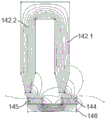
驱动器设计的另一个目标是允许驱动器在驱动器定子132和驱动器线圈131之间以及嵌入转子121内的永久驱动器磁体134之间留有较大气隙的情况下有效运行。尤其是,这允许叶轮120的实现而无需在叶轮叶片上安装护罩,这反而会引起高剪切应力并降低在控制流中轴向运动的效率。就这一点而言,由此产生的磁隙长度与定子和转子轭之间的总轴向驱动器高度之比,如下文相对于图4B所详细描述的那样大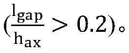
为了达到这个目的,选择驱动器的各种参数,包含驱动器定子芯132和转子121的配置,以便在驱动器的轴向力和效率之间找到更好的平衡。作为结果,该驱动器表现出与现有版本相似的性能特性,同时减少了尺寸、重量和转子惯性。To achieve this, various parameters of the drive, including the configuration of the
在考虑驱动器参数时,必须考虑永磁驱动器产生的电磁转矩(Tel),可以将其公式化为正交电流(iq)与磁通链(ψf)的乘积:When considering the drive parameters, the electromagnetic torque (T el ) produced by the permanent magnet drive must be considered, which can be formulated as the product of the quadrature current (i q ) and the flux linkage (ψ f ):
Tel=ψf·iq T el =ψ f ·i q
磁通链是永磁通量的一部分,其穿过气隙并通过定子磁极132.1和磁轭132.2闭合。磁通链取决于在该路径上穿过线圈的总磁通φf,以及线圈匝数N:The flux linkage is the part of the permanent magnetic flux that crosses the air gap and is closed by the stator poles 132.1 and the yoke 132.2. The flux linkage depends on the total flux φ f passing through the coil on this path, and the number of coil turns N:
ψf=N·φf ψ f =N·φ f
因此,转矩取决于驱动器线圈131的匝数和产生的总磁通量。Therefore, the torque depends on the number of turns of the
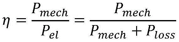
驱动器的效率(η)是机械输出功率(Pmech)和电输入功率(Pel)的商。由于涡流和磁滞,主要的功率损耗(Ploss)是铜绕组损耗(Pcu)和定子铁芯损耗(Pcore)。The efficiency (η) of a drive is the quotient of the mechanical output power (P mech ) and the electrical input power (P el ). The main power losses (P loss ) are copper winding losses (P cu ) and stator core losses (P core ) due to eddy currents and hysteresis.
Ploss≈Pcu+Pcore P loss ≈P cu +P core
驱动器的主要功率损耗是在驱动器线圈的铜绕组中产生的。这是由于机器尺寸和大气隙,由于边缘效应减小了磁通链,因此需要更大的电流才能产生转矩。铜损与定子相电阻和电流的平方成正比。The main power loss in the driver is in the copper windings of the driver coil. This is due to the size of the machine and the large air gap, which requires more current to generate torque due to the reduced flux linkage due to fringe effects. Copper losses are proportional to the stator phase resistance and the square of the current.
铜损是主损耗,并受几何形状变化的影响。随着负载变化,铜损随着驱动器的工作点(速度/转矩)而变化。Copper losses are the main losses and are affected by changes in geometry. Copper losses vary with the operating point (speed/torque) of the drive as the load changes.
驱动器马达常数KMotor以消除对驱动器电流的依赖性的方式表示转矩和铜损的关系。因此,对于槽中恒定的铜截面面积,是测量驱动器马达常数的标准,而与工作点或所选导线的厚度无关。The drive motor constant K Motor expresses the relationship between torque and copper loss in a manner that eliminates the dependence on the drive current. Therefore, for a constant copper cross-sectional area in the slot, it is the criterion for measuring the constants of the drive motor, regardless of the operating point or the thickness of the selected wire.
驱动器几何约束和目标Drive Geometry Constraints and Goals
将驱动器集成到泵中的要求对泵的设计提出了许多几何约束和目标。The requirement to integrate the drive into the pump imposes many geometric constraints and goals on the design of the pump.
例如,定子铁芯和线圈的外半径受到限制(最大约55mm),以限制泵的总外直径,而驱动器的内半径则必须最小为10.5mm,以允许为左侧泵入口留出足够的空间,并且尤其是允许更大的入口直径,从而可以提高液压效率和流量特性,从而提供更大的流出压力敏感性。定子的轴向高度应该最小化,以减少总泵长度。For example, the outer radii of the stator core and coils are limited (approximately 55mm max) to limit the overall outer diameter of the pump, while the inner radius of the drive must be a minimum of 10.5mm to allow sufficient space for the left pump inlet , and in particular allow for a larger inlet diameter, which can improve hydraulic efficiency and flow characteristics, thereby providing greater outflow pressure sensitivity. The axial height of the stator should be minimized to reduce the total pump length.
总组件的重量应该最小化,转子组件的重量应该最小化,以减少转子惯性,从而改善动态泵的性能和效率,尤其是在以脉冲或调制速度曲线运行时。The weight of the total assembly should be minimized, and the weight of the rotor assembly should be minimized to reduce rotor inertia, thereby improving dynamic pump performance and efficiency, especially when operating on pulsed or modulated speed profiles.
转子和驱动器定子之间的轴向磁隙设置为3mm+-叶轮的轴向移动范围的较大值。这允许具有增加的高度的半开式叶轮叶片穿过磁隙中的体积。通常,通过增加最小流动路径面积(尤其是在叶片的入口孔处)来减小流动阻力,从而提高液压效率和流出压力敏感性,并且避免了需要叶轮护罩(携带磁体)的问题,该问题会增加溶血和其他相关血液相容性问题的危险。The axial magnetic gap between the rotor and the drive stator is set to 3mm+- the larger value of the axial movement range of the impeller. This allows half-open impeller blades of increased height to pass through the volume in the magnetic gap. In general, flow resistance is reduced by increasing the minimum flow path area (especially at the inlet holes of the vanes), thereby improving hydraulic efficiency and outflow pressure sensitivity, and avoiding the need for impeller shrouds (carrying magnets), which Increased risk of hemolysis and other related blood compatibility problems.
可以为驱动器调整的参数示例如图4A和4B所示,并汇总在下表1中。Examples of parameters that can be adjusted for the drive are shown in Figures 4A and 4B and summarized in Table 1 below.
表1Table 1

驱动器定子槽宽度Drive stator slot width
现在将参照图5A至图5C描述改变驱动器定子槽宽度的效果的示例。An example of the effect of changing the driver stator slot width will now be described with reference to Figures 5A-5C.
在这方面,驱动器定子槽的宽度对应于相邻的驱动器定子极132.1之间的空间,并以多种相互冲突的方式影响驱动器。In this regard, the width of the driver stator slots corresponds to the space between adjacent driver stator poles 132.1 and affects the driver in a number of conflicting ways.
例如,增加驱动器定子槽的宽度会减小极面面积,导致轴向力Fz也减小。当气隙大时,杂散磁通的感性部分增加,并且更少的永磁通量穿过轴向间隙并通过定子闭合,这意味着ψf减小,因此马达常数KMotor并且因此驱动器马达常数减小。For example, increasing the width of the driver stator slots reduces the pole face area, resulting in a reduction in the axial force Fz . When the air gap is large, the inductive part of the stray flux increases, and less permanent magnet flux passes through the axial gap and is closed by the stator, which means that ψf decreases and therefore the motor constant K Motor and thus the drive motor constant decreases Small.
然而,随着驱动器定子槽横截面面积的增加,如在图5B中示出,驱动器线圈131中的绕组数量增加。因此,更多的磁通φf穿过更多的绕组匝数,因此ψf增加并且马达常数KMotor增加。However, as the driver stator slot cross-sectional area increases, as shown in Figure 5B, the number of windings in the
然而,额外的匝数意味着驱动器线圈电阻增加,因为额外的匝数增加了总导线长度,这反过来又增加了铜损,因此部分抵消了马达常数KMotor的增加。However, the extra turns mean an increase in the driver coil resistance, as the extra turns increase the overall wire length, which in turn increases copper losses, thus partially offsetting the increase in the motor constant, K Motor .
或者,可以在较大的槽中使用较大直径的导线以保持原始槽中存在的线圈数,但是较大直径的导线将具有较小的电阻,因此可以提高较大槽驱动器的效率。Alternatively, a larger diameter wire could be used in the larger slot to maintain the number of coils present in the original slot, but the larger diameter wire will have less resistance and therefore increase the efficiency of the larger slot driver.
驱动器的内半径由于端部绕组匝数变大而减小,从而导致入口区域的空间变小,体积和重量增加,从而引起进一步的影响。另外,由于减小了定子芯的体积,从而减小了定子磁性材料的极面表面积,因此随着驱动器定子槽宽度的增加,永磁体的轴向吸引力逐渐减小。Further effects are caused by the reduction in the inner radius of the driver due to the larger number of end winding turns, resulting in less space in the entry area and increased volume and weight. In addition, since the volume of the stator core is reduced, thereby reducing the pole surface surface area of the stator magnetic material, the axial attraction force of the permanent magnet gradually decreases as the width of the driver stator slot increases.
作为结果,如在图5C中示出,从最小的驱动器定子槽缝宽度开始,由于绕组匝数的增加,驱动器马达常数(代表驱动器马达常数)开始增加。在较高的槽宽处,由于增加的定子电阻和减少的渗透定子绕组的磁链的作用,效率降低会抵消这种影响。因此,可以找到特定驱动器定子槽宽度的最大驱动器马达常数。As a result, as shown in Figure 5C, starting from the smallest driver stator slot width, the driver motor constant (representing the driver motor constant) starts to increase due to the increase in the number of winding turns. At higher slot widths, this effect is offset by a reduction in efficiency due to the effect of increased stator resistance and reduced flux linkage penetrating the stator windings. Therefore, the maximum drive motor constant for a particular drive stator slot width can be found.
作为这些考虑的结果,相邻的驱动器定子极被驱动器定子槽分开,该驱动器定子槽的宽度至少在4mm至7.4毫米之间,更通常为约6mm。As a result of these considerations, adjacent driver stator poles are separated by driver stator slots having a width of at least between 4mm and 7.4mm, more typically about 6mm.
驱动器定子芯尺寸Driver stator core size
驱动器定子芯尺寸的影响与驱动器定子槽的宽度密切相关,并且具有类似的考虑因素,现在将参考图6A至6C进行描述。The effect of driver stator core size is closely related to the width of the driver stator slots, and has similar considerations, as will now be described with reference to Figures 6A to 6C.
尤其是,增加驱动器定子芯的内芯半径可减少极面面积和有效槽长度(ro–ri)。因此,可以产生的轴向力Fz减少,所产生的转矩Tel也减小。In particular, increasing the inner core radius of the driver stator core reduces the pole face area and effective slot length (r o –r i ). As a result, the axial force F z that can be generated is reduced, and the torque Tel generated is also reduced.
在图6A和图6B的示例中,内半径ri从14mm增加到16mm,导致力Fz和驱动器马达常数Kmotor减少,如图6C中的箭头600所示。In the example of Figures 6A and 6B, the inner radius ri is increased from 14 mm to 16 mm, resulting in a decrease in force F z and driver motor constant K motor , as indicated by
沿下部曲线示出了将驱动器定子槽的宽度从4mm减小到7mm,而箭头601显示了永磁体厚度增加的影响。Reducing the width of the driver stator slots from 4mm to 7mm is shown along the lower curve, while
作为这些考虑的结果,驱动器定子的内半径通常在12mm至20mm之间,在14mm至18mm之间,更通常为约16mm。As a result of these considerations, the inner radius of the drive stator is typically between 12mm and 20mm, between 14mm and 18mm, and more typically around 16mm.
相比之下,驱动器定子的外半径主要受几何因素的影响,其目标是在物理上具有尽可能大的直径,足以安装在外壳内,并能够在驱动器定子芯外缘与外壳之间容纳线圈厚度。因此,驱动器定子芯的外半径在22mm至25mm之间,更通常约为24.5mm。In contrast, the outer radius of the drive stator is primarily governed by geometry, with the goal of being physically as large as possible to fit within the housing and to accommodate the coils between the outer edge of the drive stator core and the housing. thickness. Therefore, the outer radius of the driver stator core is between 22mm and 25mm, more typically around 24.5mm.
驱动器绕组配置Driver Winding Configuration
优选的绕组配置是集中式双层绕组。这允许减小端部绕组的尺寸,以允许马达的大内直径。驱动器极的配置,尤其是定子槽和转子中磁体的数量的组合受永磁驱动器的一般原理支配。一些可行的组合可以导致更高的绕组系数,从而减少焦耳损耗,这可能伴随着磁动势的更高谐波含量,从而导致转子损耗增加。然而,相对大的气隙对场谐波具有低通滤波效果,因此最好减小焦耳损耗。因此,驱动器磁体的数量通常为8、10、14和16之一,而定子槽的数量通常为12、15和18中的一种,首选配置为10个驱动器磁体和12个定子槽。The preferred winding configuration is a concentrated double layer winding. This allows the size of the end windings to be reduced to allow for a large inner diameter of the motor. The configuration of the drive poles, especially the combination of stator slots and the number of magnets in the rotor, is governed by the general principles of permanent magnet drives. Some possible combinations can lead to higher winding coefficients and thus reduced Joule losses, which may be accompanied by higher harmonic content of the magnetomotive force, leading to increased rotor losses. However, a relatively large air gap has a low-pass filtering effect on field harmonics, so it is best to reduce Joule losses. Therefore, the number of drive magnets is typically one of 8, 10, 14, and 16, while the number of stator slots is typically one of 12, 15, and 18, with a preferred configuration of 10 drive magnets and 12 stator slots.
尽管驱动器马达常数KMotor与线尺寸无关,但线尺寸和匝数受电源限制的影响。马达的最大运行速度取决于电源电压克服永久性驱动器磁体在马达线圈中感应的反电动势(EMF)的能力以及系统中的电阻损耗。马达可产生的最大转矩与电马达电流和马达转矩常数成正比,并受可提供的电流量限制,而不会超过传动系统和马达的热阈值。Although the drive motor constant K Motor is independent of wire size, wire size and number of turns are affected by power supply limitations. The maximum operating speed of the motor depends on the ability of the supply voltage to overcome the back electromotive force (EMF) induced in the motor coils by the permanent drive magnets and resistive losses in the system. The maximum torque a motor can produce is proportional to the electric motor current and the motor torque constant, and is limited by the amount of current that can be supplied without exceeding the thermal thresholds of the driveline and motor.
对于固定的槽尺寸和线圈铜面积,增加线圈匝数会增加给定转子速度下的感应反电动势,从而降低给定电源电压下可获得的最大速度。然而,这将减小转矩常数,从而允许在最大电源电流下产生更高的转矩。反之,转数越小,则最大速度越高,而最大转矩则越小。如本领域中已知的,以星形或三角形配置缠绕马达也可以用于操纵最大速度和最大转矩之间的权衡。For a fixed slot size and coil copper area, increasing the number of coil turns increases the induced back EMF at a given rotor speed, thereby reducing the maximum speed achievable at a given supply voltage. However, this will reduce the torque constant, allowing higher torque to be produced at maximum supply current. Conversely, the smaller the number of revolutions, the higher the maximum speed and the smaller the maximum torque. Winding motors in a star or delta configuration can also be used to manipulate the trade-off between maximum speed and maximum torque, as is known in the art.
在电池供电的应用中,电池电压会限制电源电压。对于具有经皮动力传动系统的可植入装置,马达导体的最大厚度以及最大电流容量受经皮动力传动系统直径的限制。因此,对于带有便携式控制器的植入式血泵,最大电源电压通常在12V至30V之间,更通常为大约24V,最大电源电流在3A至8A之间,更通常为大约5A。In battery powered applications, the battery voltage limits the supply voltage. For implantable devices with a percutaneous powertrain, the maximum thickness of the motor conductors, as well as the maximum current capacity, is limited by the diameter of the percutaneous powertrain. Thus, for an implantable blood pump with a portable controller, the maximum supply voltage is typically between 12V and 30V, more typically around 24V, and the maximum supply current is between 3A and 8A, more typically around 5A.
如表2所示,对三种这样的马达线圈匝数配置进行了评估。对马达进行了测试,以确定在相同的最大电源电压和最大电源电流下,它们的最大速度和最大转矩所定义的性能范围,结果如图6D所示。As shown in Table 2, three such motor coil turns configurations were evaluated. The motors were tested to determine the performance range defined by their maximum speed and maximum torque at the same maximum supply voltage and maximum supply current, and the results are shown in Figure 6D.
表2Table 2
配置A提供了最低的最大转矩,但提供了最高的最高速度。配置B提供最高的最大转矩和最低的最大速度。配置C提供了高转矩和高速度的组合,在其他两种设计之间做出了折衷。对于预期运行速度范围为1500-2500RPM的旋转血泵,与配置A相比,配置B或C的使用可在预期运行范围内提供额外的最大转矩。Configuration A provides the lowest maximum torque, but the highest top speed. Configuration B provides the highest maximum torque and the lowest maximum speed. Configuration C offers a combination of high torque and high speed, a compromise between the other two designs. For rotary blood pumps with an expected operating speed range of 1500-2500 RPM, the use of configuration B or C can provide additional maximum torque over the expected operating range compared to configuration A.
驱动器磁体形状Drive Magnet Shape
现在将分别参照图7A至7C描述驱动器磁体形状的影响的示例。Examples of the influence of driver magnet shape will now be described with reference to Figures 7A to 7C, respectively.
出于本示例的目的,假设驱动器磁体沿弧形段延伸。首先要考虑的是磁体节距am(或弧长),其会影响相邻的驱动器磁体之间的杂散磁通。在这方面,图7A和7B,显示了针对不同驱动器磁体节距(弧角)的通过驱动器定子极和驱动器磁体的磁通量的图形表示。这突出表明,对于较大的节距角,对应于相邻驱动器磁体之间的间距减小,这导致杂散磁通路径更短,因此与较小的节距角相比,驱动器定子与驱动器磁体之间的磁链减小了,从而导致减小轴向力Fz。然而,相反,如果节距角太小,则会降低驱动器磁体的整体强度,从而再次减小轴向力Fz。这种变化的一个示例如图7C所示,突出显示了最佳节距角。For the purposes of this example, it is assumed that the drive magnets extend along arcuate segments. The first consideration is the magnet pitch am (or arc length), which affects the stray flux between adjacent drive magnets. In this regard, Figures 7A and 7B, show graphical representations of the magnetic flux through the driver stator poles and driver magnets for different driver magnet pitches (arc angles). This highlights that for larger pitch angles, corresponding to a reduction in the spacing between adjacent driver magnets, this results in shorter stray flux paths, and thus the driver stator and driver The flux linkage between the magnets is reduced, resulting in a reduced axial force Fz . Conversely, however, if the pitch angle is too small, the overall strength of the driver magnets will be reduced, again reducing the axial force F z . An example of this variation is shown in Figure 7C, highlighting the optimal pitch angle.
此外,可以理解的是,增加驱动器磁体的厚度会增加磁体的强度,从而增加轴向力,如图7C的曲线图中的连续线所示。如图7C所示,这也导致效率提高。然而,这也增加了转子的重量,从而增加了转子的惯性,并受到转子物理尺寸的限制。Furthermore, it will be appreciated that increasing the thickness of the driver magnet will increase the strength of the magnet, thereby increasing the axial force, as shown by the continuous line in the graph of Figure 7C. As shown in Figure 7C, this also leads to increased efficiency. However, this also adds weight to the rotor, which increases the rotor's inertia and is limited by the physical size of the rotor.
如图7D所示,驱动器磁体轴向厚度hPM和驱动器磁体节距或弧长am的变化也会影响马达常数。尽管永磁体(PM)角度和厚度的变化可以返回一定范围的吸引力,但是所产生的吸引力与马达常数之间存在很强的相关性。这样,可以选择满足给定轴向力马达常数要求的多个PM几何形状。因此,应考虑这些不同的PM几何形状对转子和泵设计的物理影响。As shown in Figure 7D, changes in the driver magnet axial thickness h PM and the driver magnet pitch or arc length am also affect the motor constant. Although changes in permanent magnet (PM) angle and thickness can return a range of attractive forces, there is a strong correlation between the resulting attractive forces and motor constants. In this way, multiple PM geometries can be selected that meet the requirements of a given axial force motor constant. Therefore, the physical impact of these different PM geometries on rotor and pump design should be considered.
因此,可以理解的是,可以选择驱动器磁体的节距角,以使永磁体的材料利用率(效率)最大化。因此,每个驱动器磁体沿着弧段延伸,相交角度至少为15°到36°之间,最好为约25°。Thus, it will be appreciated that the pitch angle of the driver magnets can be selected to maximize the material utilization (efficiency) of the permanent magnets. Thus, each driver magnet extends along an arc segment at an angle of intersection of at least between 15° and 36°, preferably about 25°.
一旦确定了驱动器磁体的节距角,就可以选择磁体的高度,以调节驱动器转矩Kmotor和轴向力Fz的性能。在这方面,每个驱动器磁体的厚度通常在0.8mm至3mm之间,并且更典型地为约2.6mm。在一个示例中,驱动器磁体的等级为BHmax=48。Once the pitch angle of the drive magnets is determined, the height of the magnets can be selected to tune the performance of the drive torque K motor and axial force F z . In this regard, the thickness of each driver magnet is typically between 0.8mm and 3mm, and more typically about 2.6mm. In one example, the driver magnets are rated BH max =48.
驱动器轭形状Driver Yoke Shape
提供了驱动器定子轭和转子驱动器轭,以确保相邻的驱动器磁体和驱动器定子极之间的磁链。由此,选择通常由软铁制成的转子驱动器轭和通常由软磁复合材料(SMC)(例如Somaloy)制成的驱动器定子轭,以使其具有足够的横截面积以提供足够的磁链,从而最大程度地减小各自的重量。复合磁轭的使用可能是有益的,因为烧结特性消除了创建叠片铁芯的需要,传统上需要叠片铁芯减少涡流损耗并提高效率。但是,将轴向磁通马达的芯叠层需要创建同心的“树”形环,这很难制造。在适当的情况下,轴承和马达的转子轭元件可以组合在一起,只要考虑到马达和轴承的组合饱和特性来选择组合厚度即可。Driver stator yokes and rotor driver yokes are provided to ensure flux linkage between adjacent driver magnets and driver stator poles. Thus, the rotor drive yoke, usually made of soft iron, and the drive stator yoke, usually made of soft magnetic composite material (SMC) such as Somaloy, are chosen to have sufficient cross-sectional area to provide adequate flux linkage , thereby minimizing their respective weights. The use of composite yokes can be beneficial because the sintered nature eliminates the need to create a laminated core, which is traditionally required to reduce eddy current losses and improve efficiency. However, stacking the cores of an axial flux motor requires creating concentric "tree" rings, which are difficult to manufacture. Where appropriate, the bearing and rotor yoke elements of the motor may be combined together, as long as the combined thickness is chosen taking into account the combined saturation characteristics of the motor and bearing.
在一个示例中,驱动器定子和转子驱动器轭132.2、135的厚度分别在1mm至5mm之间,在1.5mm至2.5mm之间,更典型地在约1.75至1.9mm之间。转子驱动器轭可以是单独的元件,也可以与转子轴承轭结合使用。In one example, the thickness of the driver stator and rotor driver yokes 132.2, 135, respectively, is between 1 mm and 5 mm, between 1.5 mm and 2.5 mm, and more typically between about 1.75 and 1.9 mm. The rotor drive yoke can be a separate element or used in combination with the rotor bearing yoke.
驱动器定子槽深度Drive stator slot depth
现在将分别参照图8A至图8C描述驱动器定子槽深度的影响的示例。An example of the effect of driver stator slot depth will now be described with reference to Figures 8A to 8C, respectively.
在这方面,增加驱动器定子槽的深度允许增加驱动器线圈131中的绕组的数量,而不会像增加槽的宽度那样相应地减小极面面积。因此,增加驱动器定子槽的深度可以增加驱动器转矩和效率,如在图8C中示出,而轴向力Fz不变。In this regard, increasing the depth of the driver stator slots allows to increase the number of windings in the
应当指出的是,尽管由于通过定子的铁路径较长而导致磁路的磁阻(magneticresistance)增加,从而导致磁场通量链变小,但由于增加的铁长度的磁阻在比大气隙的磁阻小1000倍的范围内,所以这种影响可忽略不计。It should be noted that although the magnetic resistance of the magnetic circuit is increased due to the longer iron path through the stator, resulting in a smaller magnetic field flux chain, the magnetic resistance due to the increased iron length is lower than the magnetic resistance of the large air gap. The resistance is in the range of 1000 times smaller, so this effect is negligible.
如果驱动槽有效地填充了与之前相同直径的线圈,则将驱动器定子槽的深度加倍还会导致线圈电阻加倍,磁链也加倍。If the drive slots are effectively filled with coils of the same diameter as before, doubling the depth of the drive stator slots also results in doubling the coil resistance, as well as doubling the flux linkage.
因此,可以理解,增加驱动器定子槽的深度通常可以提高系统的性能。然而,这需要通过几何约束来平衡,尤其是希望最小化驱动器定子和泵的长度和重量。Therefore, it can be appreciated that increasing the depth of the driver stator slots can generally improve the performance of the system. However, this needs to be balanced by geometric constraints, especially the desire to minimize the length and weight of the drive stator and pump.
因此,在一个示例中,上述的其他参数被优化,并选择了驱动器定子槽的深度,以确保获得所需的驱动器转矩和效率。在一个示例中,驱动器定子槽的深度选择在4mm至14mm之间,通常约为11.25mm。Therefore, in one example, the other parameters described above are optimized and the depth of the drive stator slots is selected to ensure that the desired drive torque and efficiency are obtained. In one example, the depth of the driver stator slots is chosen to be between 4mm and 14mm, typically about 11.25mm.
从以上将认识到,几何形状变化的组合可以被结合以获得关于设计目的的初衷。尤其是,永久驱动器磁体几何形状的变化允许调整效率/力之比Kmotor/Fz,并执行参数更改以减小驱动器定子和转子组件的体积/重量,同时确保满足效率和力的要求。From the above it will be appreciated that combinations of geometrical changes can be combined to achieve the original intent for design purposes. In particular, changes in permanent drive magnet geometry allow tuning of the efficiency/force ratio K motor /F z and parameter changes to be performed to reduce the volume/weight of the drive stator and rotor assemblies while ensuring that efficiency and force requirements are met.
下表3中列出了不同参数的首选和可选范围的总结,具体值在图8F中进一步显示:A summary of preferred and optional ranges for different parameters is presented in Table 3 below, with specific values further shown in Figure 8F:
表3table 3
这些参数变化允许驱动器系统的设计在几何约束范围内,并且驱动器系统可以在很大的磁隙上运行,同时仍然满足特定的轴向力要求并使效率最大化。These parameter changes allow the design of the drive system to be within geometric constraints and the drive system to operate over a large magnetic gap, while still meeting specific axial force requirements and maximizing efficiency.
在一个示例中,这允许转子的第一面和腔体的第一端之间的间距至少为如下之一:在使用中在2mm至5mm之间,在使用中在2.0mm至3mm之间,并且在使用中大约为2.3mm(±叶轮的轴向移动)。类似的,这可以使定子磁极面和驱动器磁体面之间的间距在使用中至少为如下之一:在使用中在2.5mm至6mm之间,在使用中在2.5mm至4mm之间以及在使用中大约3.2mm(±叶轮的轴向移动)。替代地,这可以允许定子轭和驱动器磁体之间的间隔至少为如下之一:在使用中在7mm至25mm之间,在使用中在8mm至20mm之间以及在使用中约17.mm(±叶轮的轴向移动),或在使用中定子极面与驱动器磁轭之间的间隔至少为4mm至8mm之间,在使用中在4.5mm至7mm之间,并且在使用中在约5.8mm(±叶轮的轴向运动)。In one example, this allows the spacing between the first face of the rotor and the first end of the cavity to be at least one of: between 2mm and 5mm in use, between 2.0mm and 3mm in use, And in use is about 2.3mm (± the axial movement of the impeller). Similarly, this allows the spacing between the stator pole face and the driver magnet face to be at least one of the following in use: between 2.5mm and 6mm in use, between 2.5mm and 4mm in use, and about 3.2mm (± the axial movement of the impeller). Alternatively, this may allow the spacing between the stator yoke and the driver magnet to be at least one of: between 7mm and 25mm in use, between 8mm and 20mm in use, and in use about 17.mm (± axial movement of the impeller), or the spacing between the stator pole faces and the drive yoke is at least between 4mm and 8mm in use, between 4.5mm and 7mm in use, and about 5.8mm in use ( ± axial movement of the impeller).
这是有利的,因为允许转子的第一面和腔体的第一端之间的间隔在使用中至少为2.3mm,这又允许将叶片安装在转子的第一面上,在转子的第一面与腔体的第一端之间,叶片的高度在1.5mm至5mm之间、在1.5mm至2.5mm之间、在1.8mm至2.2mm之间、和约2mm,从而避免了在叶片上安装护罩的需要,如前所述,同时在使用时允许叶轮轴向移动最大±0.3mm。This is advantageous as the spacing between the first face of the rotor and the first end of the cavity is allowed to be at least 2.3mm in use, which in turn allows the vanes to be mounted on the first face of the rotor where the first Between the face and the first end of the cavity, the height of the blade is between 1.5mm and 5mm, between 1.5mm and 2.5mm, between 1.8mm and 2.2mm, and about 2mm, thus avoiding the installation on the blade The need for a shroud, as previously described, also allows for a maximum of ±0.3mm of axial movement of the impeller when in use.
尽管将驱动器系统的磁隙最小化以提高效率是传统的设计理念,但是由于能够容纳的叶片高度明显更高,因此增加的磁隙在血泵的设计中可能是有利的。图8D示出较高的叶轮叶片可以减小压力-流量泵曲线的梯度的绝对值。该降低的泵梯度可以改善设备与循环系统的生理相互作用。如此,具有很大气隙的马达的设计可能对旋转式血泵设计有利。Although minimizing the magnetic gap of the drive system to improve efficiency is a traditional design concept, the increased magnetic gap may be beneficial in the design of blood pumps due to the significantly higher vane heights that can be accommodated. Figure 8D shows that taller impeller blades can reduce the absolute value of the gradient of the pressure-flow pump curve. This reduced pump gradient can improve the physiological interaction of the device with the circulatory system. As such, designs of motors with very large air gaps may be advantageous for rotary blood pump designs.
尽管马达磁隙的增加会固有地降低设备的效率,但是通过操纵上述参数,可以创建一个马达,其马达常数与较小的气隙马达相似,如图8E所示。特别地,这可以通过在增加磁体体积和/或磁化等级方面增加永磁体强度来实现。Although an increase in the motor magnetic gap inherently reduces the efficiency of the device, by manipulating the above parameters, it is possible to create a motor with a motor constant similar to that of a smaller air-gap motor, as shown in Figure 8E. In particular, this can be achieved by increasing the permanent magnet strength in terms of increasing magnet volume and/or magnetization level.
轴承设计Bearing Design
如前所述,转子利用来自驱动器和磁体轴承的磁力在轴向上达到平衡。为了最大程度地减少能耗,磁体轴承和驱动器被构成为使得,当转子在正常运行速度下的平衡点处提供,例如可以大约为在正常流动条件下腔体的中心时,由驱动器和轴承引起的轴向力基本平衡。As previously mentioned, the rotor is axially balanced using magnetic forces from the drive and magnet bearings. To minimise energy consumption, the magnet bearings and drives are constructed such that, when the rotor is provided at an equilibrium point at normal operating speeds, which may for example be approximately the centre of the cavity under normal flow conditions, caused by the drive and bearings The axial force is basically balanced.
然后使用闭环反馈系统在轴向上主动悬浮转子,在该系统中,传感器160检测转子位置,控制器150确定将转子定位在所需设定点所需的磁体轴承电流。因此,驱动器吸引力、磁体轴承的被动吸引力和任何外部轴向力之间的差异通过磁体轴承的电磁力来平衡。驱动器和被动磁体轴承力匹配的点是平衡点bz,它是根据外壳中的位置和反作用力bF的大小来定义的。The rotor is then actively suspended in the axial direction using a closed loop feedback system in which
根据泵的流量要求选择所需的设定点。在这方面,控制叶片和腔体壁之间的物理间隔可调节相应的叶轮的效率,因此可用于控制流量。如其他地方所述,在整个人工心脏(TAH)中,因此,可以通过移动叶轮来实现左右侧泵之间的相对流量控制。Select the desired set point based on the flow requirements of the pump. In this regard, controlling the physical separation between the vanes and the cavity wall can adjust the efficiency of the corresponding impeller and thus can be used to control flow. As described elsewhere, in the Total Artificial Heart (TAH), therefore, relative flow control between the left and right pumps can be achieved by moving the impellers.
在一个示例中,控制器150可以实现虚拟零功率控制器,该控制器试图移动转子,以将磁性轴承使用的平均电流控制到给定水平(例如0A)。在这种情况下,对于作用在转子上的给定外力,由控制器150引起的转子运动量由转子轴向被动力刚度(kFz)决定,具体如下:In one example, the
其中:Fz是轴向力where: F z is the axial force
对于全人造心脏的应用,应根据预期的液压力和所需的运动来选择由作用在转子上的液压力产生的VZP(虚拟零功率)运动,以平衡这些力并改善流量平衡。如此,有利的是,将系统部件设计成使得轴向被动力刚度与期望的液压力匹配。For total artificial heart applications, the VZP (virtual zero power) motion produced by the hydraulic force acting on the rotor should be chosen according to the expected hydraulic force and the desired motion to balance these forces and improve flow balance. As such, it is advantageous to design system components such that the axial passive stiffness is matched to the desired hydraulic pressure.
两个吸引力相等的轴向位置是转子将以零稳态电流和零外力平衡的点。图9A示出了一个例子。The axial position where the two attractive forces are equal is the point at which the rotor will balance with zero steady state current and zero external force. FIG. 9A shows an example.
尤其是,在该示例中,当转子居中时(转子位置0),驱动器吸引力和轴承吸引力等于24.5N。如果转子向左移动,朝向驱动器方向移动,则驱动器吸引力增大,而轴承吸引力减小,从而导致朝向驱动器的净力增加。如果转子向右移动,则情况相反。应当理解,通过使用主动磁性轴承来抵消驱动力和轴承力的差异,可以控制这种固有的不稳定性。In particular, in this example, when the rotor is centered (rotor position 0), the drive attraction force and the bearing attraction force equal 24.5N. If the rotor moves to the left, towards the drive, the drive attraction increases and the bearing attraction decreases, resulting in an increase in the net force towards the drive. The opposite is true if the rotor moves to the right. It will be appreciated that this inherent instability can be controlled by using active magnetic bearings to counteract the difference in driving and bearing forces.
力差(kFz[N/mm])的梯度由驱动器轴向力刚度(kF,MTR,z)和磁性轴承轴向力刚度(kF,MB,z)组成,如图9B中示出。其中驱动器轴向力是FMTR,z,并且磁性轴承轴向力是FMB,z。The gradient of the force difference (k Fz [N/mm]) consists of the drive axial force stiffness (k F,MTR,z ) and the magnetic bearing axial force stiffness (k F,MB,z ), as shown in Figure 9B . where the drive axial force is F MTR,z and the magnetic bearing axial force is F MB,z .
对于给定的外部轴向力(N)的变化,总力刚度kFz的大小决定了转子的轴向运动(dz)。For a given change in external axial force (N), the magnitude of the total force stiffness k Fz determines the axial movement of the rotor (dz).

kFz的值应当被设计成能够实现所需的轴向运动,以改变由作用在转子上的压力引起的外力变化。The value of kFz should be designed to achieve the desired axial movement to change the change in external force caused by the pressure acting on the rotor.
除了考虑轴向刚度外,还必须考虑轴承的径向刚度。在这方面,在现有技术的配置中,转子通常通过使用径向轴承(例如流体动力轴颈轴承)沿径向悬浮。然而,这种配置依赖于在转子和腔体侧壁之间保持最小的间隔,这又导致了高剪切应力的区域,这又可能导致溶血和血液中其他形成元件的破坏。因此,期望提供替代的径向悬浮机构。In addition to considering the axial stiffness, the radial stiffness of the bearing must also be considered. In this regard, in prior art configurations, the rotor is typically suspended radially through the use of radial bearings, such as hydrodynamic journal bearings. However, this configuration relies on maintaining a minimum separation between the rotor and the cavity sidewall, which in turn leads to areas of high shear stress, which in turn can lead to hemolysis and destruction of other forming elements in the blood. Therefore, it would be desirable to provide an alternative radial suspension mechanism.
固有地,驱动器和磁性轴承的被动磁力对径向运动产生一定程度的限制,从而使转子至少部分地悬浮在径向方向上。径向回复力通常以径向力刚度来衡量,并且径向回复力的分布示例如图9C所示。Inherently, the passive magnetic forces of the drive and the magnetic bearings impose some degree of restriction on radial motion, so that the rotor is at least partially suspended in the radial direction. Radial restoring force is usually measured in radial force stiffness, and an example of the distribution of radial restoring force is shown in Figure 9C.
泵在径向向下接触之前可以承受的最大静态外部径向力是最大径向运动时的最大径向力。如此,有利的是增加磁性轴承和转子之间的被动径向回复力,从而轴承和驱动器可以提供所需程度的径向悬浮。The maximum static external radial force that the pump can withstand before radial downward contact is the maximum radial force at maximum radial motion. As such, it is advantageous to increase the passive radial restoring force between the magnetic bearing and the rotor so that the bearing and drive can provide the desired degree of radial suspension.
此外,系统的径向刚度以及阻尼和转子质量都会影响转子的振动响应,尤其是接近共振频率的情况。由于转子的径向运动是被动控制的,因此在选择径向刚度时应考虑到径向共振频率与设备预期运行速度范围之间的关系。由于摄取异物会增加转子的不平衡度,因此转子可能会在轴向和/或径向在旋转频率受到强制激励。接近径向共振的设备速度运行会在转子径向位置产生振动,如果没有足够的阻尼,则可能导致转子旋转并影响轴向磁性轴承系统的性能。低于此共振频率的转子运行被称为亚临界,而高于此转速的速度被称为超临界。In addition, the radial stiffness of the system as well as damping and rotor mass can affect the vibration response of the rotor, especially near the resonant frequency. Since the radial motion of the rotor is passively controlled, the radial stiffness should be chosen taking into account the relationship between the radial resonant frequency and the expected operating speed range of the equipment. Since the ingestion of foreign bodies increases the unbalance of the rotor, the rotor may be forcibly excited at the rotational frequency in the axial and/or radial direction. Equipment speed operation near radial resonance creates vibrations in the radial position of the rotor which, if not sufficiently damped, can cause the rotor to rotate and affect the performance of the axial magnetic bearing system. Rotor operation below this resonant frequency is called subcritical, while speeds above this speed are called supercritical.
在运行速度范围捕获与径向共振频率一致的速度的情况下,可以增加径向刚度或减小转子质量,从而随后将径向共振频率提高到高于运行速度范围。相反,可以降低径向刚度或增加质量,以将径向共振频率降低到速度运行范围以下,但是后一种方法通常会导致径向力容量降低,并给轴向磁性轴承系统带来额外的质量。这样,在诸如此类的应用中,增加径向刚度直到径向共振频率高于工作速度范围是有利的。Where the operating speed range captures a speed consistent with the radial resonant frequency, radial stiffness can be increased or rotor mass can be reduced, thereby subsequently increasing the radial resonant frequency above the operating speed range. Conversely, radial stiffness can be reduced or mass added to reduce the radial resonant frequency below the speed operating range, but the latter approach typically results in reduced radial force capacity and additional mass to the axial magnetic bearing system . Thus, in applications such as these, it is advantageous to increase the radial stiffness until the radial resonant frequency is above the operating speed range.
因此,将认识到,以上导致对磁性轴承和驱动器的特定要求。Accordingly, it will be appreciated that the above results in specific requirements for magnetic bearings and drives.
尤其是,对于给定的液压系统和泵配置,可能需要具有给定的轴向刚度kFz和平衡力bF的平衡位置bz。总刚度值是磁性轴承刚度和驱动器刚度的总和,并且磁性轴承和驱动器必须在平衡点bz上产生相同的力。In particular, for a given hydraulic system and pump configuration, a balance position bz with a given axial stiffness kFz and a balance force bF may be required. The total stiffness value is the sum of the magnetic bearing stiffness and the driver stiffness, and the magnetic bearing and driver must produce the same force at the equilibrium point b z .
除了满足以上要求,最大化轴承轴向效率(N/W0.5)和驱动器马达常数(Nm/W0.5)是有利的。In addition to meeting the above requirements, it is advantageous to maximize the bearing axial efficiency (N/W 0.5 ) and the drive motor constant (Nm/W 0.5 ).
还应当理解,为了对于给定的轴向力大小最大化轴向运动的程度,期望的是具有低轴向刚度的磁性轴承。然而,为了提供高的被动径向悬浮力容量并确保径向共振频率足够高,期望具有高的径向刚度。It will also be appreciated that in order to maximize the degree of axial motion for a given magnitude of axial force, magnetic bearings with low axial stiffness are desirable. However, in order to provide high passive radial levitation force capacity and ensure that the radial resonance frequency is high enough, it is desirable to have high radial stiffness.
尽管可以简单地通过调整(例如增加)轴承和转子的相对间距来满足平衡要求,但这会降低效率,并降低径向刚度。While balance requirements can be met simply by adjusting (eg increasing) the relative spacing of the bearings and rotor, this reduces efficiency and reduces radial stiffness.
考虑到上述因素,将理解的是,如前所述,期望配置驱动器以使其具有所需的刚度和力平衡点,同时使效率最大化。然后必须设计磁性轴承,以提供所需的刚度和力平衡点,同时使效率和径向刚度最大化。现在将进一步详细描述该过程。Taking the above into consideration, it will be appreciated that, as previously discussed, it is desirable to configure the drive to have the desired stiffness and force balance while maximizing efficiency. Magnetic bearings must then be designed to provide the required stiffness and force balance while maximizing efficiency and radial stiffness. This process will now be described in further detail.
力刚度force stiffness
轴向刚度是指定子和靶之间轴向间距变化时力的变化。单位为N/mm。可以用数学式表示为
径向刚度是径向对准变化(同时轴向间距保持恒定)时定子和靶之间力的变化。可以用数学式表示为 Radial stiffness is the change in force between the stator and the target as the radial alignment changes (while the axial spacing remains constant). can be expressed mathematically as
磁通量以及因此的磁力的来源可以是永磁体或电磁线圈中的任一个或两者。The source of the magnetic flux and thus the magnetic force can be either a permanent magnet or an electromagnetic coil or both.
磁阻/磁阻刚度Magnetoresistance / Magnetoresistance Stiffness
磁阻是电阻的磁性模拟。磁通流动的路径以及该路径中材料的磁导率决定了电路的磁阻。磁阻的SI单位是亨利,H-1。传统上,它具有脚本R的符号
诸如铁之类的材料具有很高的磁导率,当它们用于磁通路径时(例如在定子中),很容易使磁通流过它们。磁通回路中的气隙由于其低磁导率而倾向于增加磁阻。例如,当定子和靶之间的气隙增加时(也许当靶移动时),电路的磁阻增加。Materials such as iron have high magnetic permeability, and when they are used in magnetic flux paths (such as in stators), it is easy for magnetic flux to flow through them. Air gaps in the flux loop tend to increase reluctance due to their low permeability. For example, when the air gap between the stator and the target increases (perhaps when the target moves), the reluctance of the circuit increases.
磁路的磁阻较高意味着在相同的磁动势下,较少的磁通量将流动(MMF是电气系统中电压的模拟物)。A higher reluctance of a magnetic circuit means that for the same magnetomotive force, less magnetic flux will flow (MMF is an analog of voltage in an electrical system).
对应定子和靶之间相对位置变化的磁阻变化可以根据刚度来定义。可以根据运动轴,即对应沿x轴的位置变化的磁阻变化,将刚度写为

力/磁阻Force/Reluctance
对应位置变化的力(力刚度)取决于对应位置变化的回路中磁通量的变化。由于磁阻刚度是通量流动的难易程度的度量,因此这些量本质上是相关的。The force (force stiffness) corresponding to a change in position depends on the change in the magnetic flux in the loop corresponding to a change in position. Since reluctance stiffness is a measure of the ease with which flux flows, these quantities are intrinsically related.
因此,力刚度是磁阻刚度的函数。Therefore, the force stiffness is a function of the magnetoresistive stiffness.

要使力刚度最大化,则意味着磁阻刚度也要最大化,反之亦然。Maximizing force stiffness means maximizing reluctance stiffness, and vice versa.
在一个实施例中,心脏泵被构造成具有至少下列之一的轴向系统刚度:至少10N/mm;至少20N/mm;至少30N/mm;至少60N/mm;至少50N/mm;约10-60N/mm;约25-50N/mm;约30-40N/mm;以及,约35-40N/mm.In one embodiment, the heart pump is configured to have an axial system stiffness of at least one of: at least 10 N/mm; at least 20 N/mm; at least 30 N/mm; at least 60 N/mm; at least 50 N/mm; about 10- 60N/mm; about 25-50N/mm; about 30-40N/mm; and, about 35-40N/mm.
刚度比stiffness ratio
刚度比可以定义为在一个轴上的刚度与另一个轴上(例如在径向与轴向上)的刚度之间的比率。The stiffness ratio can be defined as the ratio between the stiffness on one axis and the stiffness on the other axis (eg, in the radial and axial directions).
通过改变轴承的永磁强度可以增加或减小总力。然而,力的相对变化将遵循刚度比。因此,如果新设计具有较高的刚度比,则可以与以前的系统的径向刚度值相匹配,但轴向刚度较低。The total force can be increased or decreased by changing the permanent magnet strength of the bearing. However, the relative change in force will follow the stiffness ratio. Therefore, if the new design has a higher stiffness ratio, it can match the radial stiffness values of the previous system, but with lower axial stiffness.
可以通过增加给定径向运动的磁阻变化量来实现增加刚度比。这主要是通过设计高渗透性的材料(铁)来实现的,这样,当两个物体相互相对移动时,它们会改变磁通路径。Increasing the stiffness ratio can be achieved by increasing the amount of reluctance change for a given radial motion. This is mainly achieved by designing a highly permeable material (iron) so that when two objects move relative to each other, they change the magnetic flux path.
现在将参照图10A至10D描述其示例。An example thereof will now be described with reference to FIGS. 10A to 10D .
在图10A和10B的示例中,对应于转子的径向运动,使两个磁性部件,例如具有平坦的宽轮廓的轴承定子腿142.1和轴承磁体144横向移动。在该示例中,由于磁性部件的重叠径向运动不会显著改变磁通路径,因此即使执行了径向运动,磁通也有类似的路径通过,因此磁阻保持不变。In the example of Figures 10A and 10B, two magnetic components, eg bearing stator legs 142.1 and bearing
相反,在图10C和10D的配置中,磁性部件终止于尖端。在该示例中,径向运动的确会由于气隙的增加而显著改变磁通路径。因此,当零件相对于彼此横向移动时(对应于叶轮的径向位移),磁阻增加,因此提供了回复力。In contrast, in the configuration of Figures 10C and 10D, the magnetic member terminates at the tip. In this example, the radial motion does change the flux path significantly due to the increase in the air gap. Thus, as the parts move laterally relative to each other (corresponding to radial displacement of the impeller), the reluctance increases, thus providing a restoring force.
要考虑的另一种类比是静电类比,在这种类比中,磁体表面上存在恒定的“磁荷”,会产生磁场,并且当磁极尖端暴露于这些磁场时,在那些尖端上感应出的磁荷具有与磁体相应表面上的电荷相反的极性。重要的是,磁体表面上的电荷不会改变,而磁极尖端上的感应电荷却能流动并且可以在磁极表面周围移动,从而将磁场的总能量降至最低。Another analogy to consider is the electrostatic analogy, in which there is a constant "magnetic charge" on the surface of a magnet, magnetic fields are created, and when the pole tips are exposed to these magnetic fields, magnetic fields are induced on those tips The charge has the opposite polarity to the charge on the corresponding surface of the magnet. Importantly, the charge on the surface of the magnet does not change, while the induced charge on the pole tip flows and can move around the pole surface, minimizing the total energy of the magnetic field.
通过限制磁极的径向宽度,可以限制这些感应电荷在磁极表面上移动的自由度,这意味着它们只能随磁极一起移动,因此,迫使整个磁极移动到总磁能较低的位置。换句话说,施加在感应电荷上的力实际上传递到了磁极上,而不是简单地导致磁极内电荷重新分布。另外,使用渐缩的磁极会导致磁极区域中的电荷密度更高,在这些区域中,他们会产生径向力。By limiting the radial width of the poles, you limit the degrees of freedom these induced charges have to move on the pole surface, meaning they can only move with the pole, thus forcing the entire pole to move to a location with a lower total magnetic energy. In other words, the force exerted on the induced charge is actually transferred to the poles, rather than simply causing a redistribution of the charge within the poles. Additionally, using tapered poles results in higher charge densities in the pole regions, where they create radial forces.
因此,应当理解,窄的尖端导致径向刚度的增加。Therefore, it should be understood that a narrow tip results in an increase in radial stiffness.
轴承结构Bearing structure
因此,应当理解,在上述的心脏泵中,磁性轴承140被构造成在轴向方向上提供主动控制而在径向方向上提供被动稳定性。Thus, it should be appreciated that in the above-described heart pump, the
磁性轴承和转子之间的轴向力刚度由于作用在转子上的外部液压力而影响转子的相对运动。降低轴向力刚度通常通过允许转子针对由循环阻力和压力变化引起的给定液压力变化进一步运动来改善零功率控制器的操作。然而,备用的液压轴承系统的力的要求或零功率控制器的要求可决定轴向刚度的下限,以限制转子在预期的外部轴向力下的运动。The axial force stiffness between the magnetic bearing and the rotor affects the relative motion of the rotor due to external hydraulic forces acting on the rotor. Reducing the axial force stiffness generally improves the operation of the zero-power controller by allowing the rotor to move further for a given hydraulic pressure change caused by cyclic resistance and pressure changes. However, the force requirements of the backup hydraulic bearing system or the requirements of the zero power controller may determine the lower limit of axial stiffness to limit the movement of the rotor under expected external axial forces.
当转子受到外力(例如,由于叶轮圆周周围的蜗壳式收集器内压力恢复不平衡而产生的液压力,质量不平衡的转子旋转产生的同步力,或患者日常运动引起的冲击力)作用时,磁性轴承和转子之间的径向力刚度用于使转子在径向上稳定。由于转子的径向稳定性取决于磁性轴承系统的径向刚度,因此增加径向刚度可以改善设备的稳定性,并可以提高在径向触地之前可以承受的最大静力和/或冲击力。较高的径向刚度还可以确保径向共振足够高,以使转子在其整个速度范围内处于亚临界状态。When the rotor is subjected to an external force (for example, hydraulic pressure due to unbalanced pressure restoration in the volute collector around the circumference of the impeller, synchronizing force from the rotation of the rotor with unbalanced mass, or impact force caused by the patient's daily movement) , the radial force stiffness between the magnetic bearing and the rotor is used to stabilize the rotor in the radial direction. Since the radial stability of the rotor depends on the radial stiffness of the magnetic bearing system, increasing the radial stiffness can improve the stability of the equipment and can increase the maximum static and/or shock forces that can be withstood before radial contact. The higher radial stiffness also ensures that the radial resonance is high enough to keep the rotor subcritical throughout its speed range.
为了改善系统性能,磁性轴承应使径向刚度最大化,同时使轴向刚度最小。因此,磁性轴承被设计为最大化径向轴向刚度比。To improve system performance, magnetic bearings should maximize radial stiffness while minimizing axial stiffness. Therefore, magnetic bearings are designed to maximize the radial to axial stiffness ratio.
在一个示例中,这可以确保在相对于转子的径向上,全部或部分轴承定子腿142.1,142.2比磁性轴承构件144,145窄。这可以通过使整个定子腿变窄或将渐缩的相邻气隙引入到转子中的磁性材料144,145和轴承定制142的轴承定子腿142.1,142.2形成的磁路中来实现。In one example, this may ensure that all or part of the bearing stator legs 142.1, 142.2 are narrower than the
现在将参考图11A至11D描述其示例。An example thereof will now be described with reference to FIGS. 11A to 11D .
在图11A和11B的示例中,轴承定子腿142.1,142.2和磁性轴承构件144,145(在这种情况下是永磁体)不包含渐缩部。因此,如图11B所示,当转子径向运动时,磁阻变化很小,因此径向刚度最小。In the example of Figures 11A and 11B, the bearing stator legs 142.1, 142.2 and the
不同地,图11C和11D的配置中,轴承定子142的每个轴承定子腿142.1,142.2在靠近轴承定子腿的一端向内渐缩,从而在气隙附近形成了截顶的尖端。因此,图11D中示出的转子的径向运动会引起磁阻的变化,从而引起回复力,从而使径向刚度增加。11C and 11D, each bearing stator leg 142.1, 142.2 of the bearing
渐缩部可以朝向磁性轴承构件的中心线,并且通常构造成使得随着转子从中心径向位置径向偏移,来自单个轴承的径向回复力增大。The tapered portion may be towards the centerline of the magnetic bearing member, and is generally configured such that as the rotor is radially displaced from the center radial position, the radial restoring force from the single bearing increases.
因此,选择轴承定子腿142.1,142.2或磁性轴承材料144,145的几何形状,使得磁通路径随径向运动而显著变化,可以增加磁性轴承的径向刚度。Therefore, selecting the geometry of the bearing stator legs 142.1, 142.2 or the
图12A至12D中示出了图11A至11D的配置的轴向和径向刚度之间的比较的示例。An example of a comparison between the axial and radial stiffness of the configuration of FIGS. 11A to 11D is shown in FIGS. 12A to 12D .
在图12A和12B的示例中,两种设计的径向刚度和轴向气隙相匹配,使得图11A的直线轴承定子腿配置具有更大的轴向刚度,因此刚度比也更低。示例属性汇总在下表4中。表4的右栏中示出了高刚度和高平衡力轴承设计的示例。In the example of Figures 12A and 12B, the radial stiffness and axial air gap of the two designs are matched so that the linear bearing stator leg configuration of Figure 11A has a greater axial stiffness and therefore a lower stiffness ratio. Example properties are summarized in Table 4 below. Examples of high stiffness and high balance force bearing designs are shown in the right column of Table 4.
表4Table 4


在图12C和12D的示例中,通过分析针对特定轴向气隙的两种设计来匹配轴承产生的轴向平衡力,从而使图11C的渐缩的轴承定子腿配置具有更大的径向刚度,从而具有更高的刚度比。示例属性汇总在下表5中。轴向平衡力的这种等效可以在装置中通过使轴承轴向位置相对于彼此偏移或通过改变永磁材料的强度或体积来实现。表5的右栏中介绍了高刚度和高平衡力轴承设计的示例。In the example of FIGS. 12C and 12D , the tapered bearing stator leg configuration of FIG. 11C has greater radial stiffness by analyzing two designs for a specific axial air gap to match the axial balance force generated by the bearing , resulting in a higher stiffness ratio. Example properties are summarized in Table 5 below. This equivalence of the axial balancing force can be achieved in the device by offsetting the axial positions of the bearings relative to each other or by changing the strength or volume of the permanent magnet material. Examples of high stiffness and high balance force bearing designs are presented in the right column of Table 5.
表5table 5
如图13所示,可以通过渐缩轴承定子腿142.1,142.2的尖端来实现刚度比(径向刚度和轴向刚度之比)的增加,这表明随着磁极宽度减小刚度比大约呈线性增加。As shown in Figure 13, an increase in stiffness ratio (ratio of radial stiffness to axial stiffness) can be achieved by tapering the tips of the bearing stator legs 142.1, 142.2, indicating an approximately linear increase in stiffness ratio as the pole width decreases .
渐缩也可以通过其他机制来实现。例如,可以实现磁体的渐缩化,这在磁体的制造方面趋于困难,并不是特别有效。然而,可替代地,可以通过用软铁形成材料或者在永磁体144上放置极靴144.1来实现转子内轴承磁性材料的渐缩化,如图14所示。Tapering can also be achieved by other mechanisms. For example, tapering of the magnets can be achieved, which tends to be difficult in the manufacture of magnets and is not particularly efficient. Alternatively, however, tapering of the bearing magnetic material within the rotor can be achieved by forming the material from soft iron or placing pole pieces 144.1 on
从上面可以理解,可以使用轴承定子和磁性材料的各种不同结构,并且这些结构将导致不同的刚度比。图15A至15F中示出了许多示例。As can be appreciated from the above, various different configurations of bearing stator and magnetic material can be used and that these configurations will result in different stiffness ratios. A number of examples are shown in Figures 15A to 15F.
在图15A的示例中,转子中的轴承磁性材料144,145包含安装在公共轴承转子轭146上的两个磁体,而轴承定子142包含终止于平坦端部的轴承定子腿142.1,142.2,形成|Kr/Kz|=5.3%的刚度比。In the example of Figure 15A, bearing
在图15B的示例中,转子中的轴承磁性材料144,145包含两个磁体,其安装在公共轴承转子轭146上,而轴承定子142包含终止于渐缩的尖端的轴承定子腿142.1,142.2,形成|Kr/Kz|=12.9%的刚度比。In the example of Figure 15B, the bearing
在图15C的示例中,转子中的轴承磁性材料144,145包含与公共轴承转子轭146整体形成的软铁,而轴承定子142包含端接于永磁体的轴承定子腿142.1,142.2,形成|Kr/Kz|=5.4%的刚度比。In the example of Figure 15C, the bearing
在图15D的一个例子中,轴承磁性材料144包含永磁体,磁性材料145是软铁,与公用轴承转子轭146整体形成,而轴承定子142包含终止于平端的轴承定子腿142.1和安装在第二轴承定子腿142.2的一端的永磁体,形成|Kr/Kz|=6.6%的刚度比。In one example of Figure 15D, bearing
在图15E的示例中,磁性材料145和第二轴承定子腿142.2包含永磁体,而第一磁性材料和定子轴承定子腿142.1终止于平端,形成|Kr/Kz|=15.5%的刚度比。In the example of Figure 15E, the
在图15F的示例中,轴承磁性材料145包含与在第二轴承定子腿142.2上的渐缩的尖端相对的磁体,而第一磁性材料和轴承定子腿142.1终止于平端,导致|Kr/Kz|=11.0%的刚度比。In the example of Figure 15F, the bearing
图15E的配置提供了最高的刚度比,这种配置产生的轴向力约为40N,这太高了无法通过驱动器平衡被动力。因此,该配置不能在实践中使用。然而,图15B和15F的替代实施例提供足够高的刚度比和可接受的轴向力。The configuration of Figure 15E provides the highest stiffness ratio, and this configuration produces an axial force of about 40N, which is too high to balance the passive force with the driver. Therefore, this configuration cannot be used in practice. However, the alternative embodiments of Figures 15B and 15F provide a sufficiently high stiffness ratio and acceptable axial force.
图15B和15F的配置在可以使用的传感器160方面具有不同的益处。The configurations of Figures 15B and 15F have different benefits in terms of the
图15C、15D和15E的配置将永磁体直接放置在磁性定子上,这可能会带来制造挑战以及线圈局部加热的可能性,这可能会损害磁体的性能。The configurations of Figures 15C, 15D, and 15E place permanent magnets directly on the magnetic stator, which can present manufacturing challenges and the potential for localized heating of the coils, which can compromise the performance of the magnets.
在这方面,图15B的配置与图2G至2I所示的涡流传感器160一起使用,其包含三个传感器,每个传感器具有安装在外壳163中的线圈,在圆周方向上间隔开并与磁性轴承定子142的内部轴承定子腿142.2对准。线圈与转子表面垂直对准并产生磁场,而磁场在又作为转子121一部分的导电靶中感应出涡流。涡流会在磁场中产生变化,该变化是磁场、材料特性和目标位置的函数。作为结果,可以使用场变化的测量来确定传感器160与靶之间的距离,从而确定与转子121之间的距离。在一个示例中,靶是由金属表面形成的,该金属表面包裹了转子,从而提供了生物惰性的气密屏障,尽管这不是必须的,并且或者可以将导电靶嵌入到转子中。In this regard, the configuration of Figure 15B is used with the
泵壳还通常包含阻隔层材料,该阻隔层材料设计成在泵腔体内的血液与磁性轴承和马达元件之间提供气密性阻隔层,并且在生物学上也适合与血液连续接触。通常通过使用金属、陶瓷或其他合适的材料来实现。在涡流传感器附近使用非导电和非磁性的阻隔层材料(例如陶瓷)允许来自传感器的磁场穿过壳体阻隔层并与转子中的靶相互作用。然而,在涡流位置传感器附近使用导电金属阻隔层材料可以减小穿透阻隔层材料并与靶材料相互作用的场,从而降低传感器对靶以及转子运动的敏感性。在使用导电阻隔层材料的情况下,阻隔层和转子靶的设计会极大地影响材料中涡流的相对产生,因此会影响传感器对靶运动的敏感性。高灵敏度的传感器可减少引入系统的噪声,从而减少主动式磁性轴承系统的功耗,并改善悬浮性能。The pump housing also typically contains a barrier layer material designed to provide a hermetic barrier between the blood within the pump cavity and the magnetic bearing and motor elements, and which is also biologically suitable for continuous contact with the blood. This is usually achieved through the use of metals, ceramics or other suitable materials. The use of a non-conductive and non-magnetic barrier material (eg, ceramic) near the eddy current sensor allows the magnetic field from the sensor to pass through the housing barrier and interact with the target in the rotor. However, the use of a conductive metallic barrier material near the eddy current position sensor can reduce the field that penetrates the barrier material and interacts with the target material, thereby reducing the sensitivity of the sensor to target and rotor motion. In the case of a conductive barrier material, the design of the barrier and rotor target can greatly affect the relative generation of eddy currents in the material and therefore the sensitivity of the sensor to target motion. The highly sensitive sensor reduces the noise introduced into the system, which reduces the power consumption of the active magnetic bearing system and improves the suspension performance.
此外,如果将靶材料设计为使传感器磁场可以穿透靶,则必须注意靶后面材料的设计和电导率,因为它们可能会错误地影响传感器信号。例如,如果传感器磁场可以穿透转子的靶材料,则它可能与位于其后方的磁性轴承构件相互作用。由于磁性轴承构件形成在径向方向上不均匀的靶,因此可能导致传感器错误地将转子的径向运动检测为轴向位移。这样,应该尽可能地设计靶,以使传感器磁场穿过靶的穿透最小化。Furthermore, if the target material is designed so that the sensor magnetic field can penetrate the target, care must be taken with the design and conductivity of the material behind the target, as they may erroneously affect the sensor signal. For example, if the sensor magnetic field can penetrate the target material of the rotor, it may interact with a magnetic bearing member located behind it. Since the magnetic bearing member forms a target that is not uniform in the radial direction, it may cause the sensor to erroneously detect the radial movement of the rotor as an axial displacement. As such, the target should be designed as much as possible to minimize penetration of the sensor magnetic field through the target.
因此,应当理解,通过适当地选择材料以及阻隔层和靶元件的设计以及传感器线圈的设计和激励频率,可以提高传感器系统对轴向目标运动的灵敏度,同时降低对径向运动的灵敏度,如现在将要描述的。Therefore, it should be understood that with proper selection of materials and design of the barrier layer and target element, as well as the design and excitation frequency of the sensor coil, the sensitivity of the sensor system to axial target motion can be increased, while the sensitivity to radial motion can be decreased, as now will be described.
在一个示例中,靶的电导率被最大化以促进在该材料中产生涡流并使靶材料内的磁场趋肤深度最小化。最小化在靶内产生的涡流的趋肤深度,以使趋肤深度小于靶厚度,从而确保传感器场包含在靶内,并且不会明显穿透位于靶上方的材料(这可能是信号错误变化的原因)。这可以通过使用电导率相对较高的靶材料(例如商业纯Ti(1.276x10⁶Siemens/m)来实现,该靶材料的案子电导率要比阻隔层材料还要高,并且要通过使靶材料的厚度最大来实现。商业纯钛在1MHz、0.75MHz和0.5MHz时的趋肤深度分别约为0.45mm、0.52mm和0.63mm。靶材料的厚度通常在0.3毫米至1毫米之间,并且更通常约为0.6毫米。增大阻隔层的厚度也会增加磁性轴承定子的工作轴向气隙,从而降低其性能。In one example, the conductivity of the target is maximized to promote the creation of eddy currents in the material and minimize the magnetic field skin depth within the target material. Minimize the skin depth of the eddy currents created within the target so that the skin depth is less than the target thickness to ensure that the sensor field is contained within the target and does not appreciably penetrate material located above the target (this may be a false signal change) reason). This can be achieved by using a relatively high conductivity target material such as commercially pure Ti (1.276x10 6 Siemens/m), which has a higher conductivity than the barrier material, and by making the target material The thickness of commercial pure titanium is approximately 0.45mm, 0.52mm and 0.63mm at 1MHz, 0.75MHz and 0.5MHz, respectively. The thickness of the target material is usually between 0.3mm and 1mm, and more Typically about 0.6 mm. Increasing the thickness of the barrier layer will also increase the working axial air gap of the magnetic bearing stator, thereby reducing its performance.
通常将阻隔层材料的电导率最小化,以减少该材料中涡流的产生,并使该材料内产生的涡流的趋肤深度最大。为了使阻隔层材料被传感器场充分穿透,应确保在阻隔层材料中产生的涡流的趋肤深度大于阻隔层材料厚度的至少两倍,但最好为3倍或更多倍。这可以通过使用电导率相对较低的材料(例如钛合金TiAlV(5.800x10⁵ Siemens/m))以及减小靶材料的厚度,同时仍提供足够的阻隔性和结构强度来实现。TiAlV钛在1MHz、0.75MHz和0.5MHz时的趋肤深度分别约为0.66mm、0.76mm和0.94mm。阻隔层材料的厚度通常在0.1mm至0.5mm之间,并且更典型地约为0.3mm。The conductivity of the barrier material is generally minimized to reduce the generation of eddy currents in the material and to maximize the skin depth of the eddy currents generated within the material. In order for the barrier material to be sufficiently penetrated by the sensor field, it should be ensured that the skin depth of the eddy currents created in the barrier material is greater than at least twice the thickness of the barrier material, but preferably 3 times or more. This can be achieved by using relatively low conductivity materials such as the titanium alloy TiAlV (5.800× 10 5 Siemens/m) and reducing the thickness of the target material while still providing sufficient barrier and structural strength. The skin depth of TiAlV titanium at 1MHz, 0.75MHz and 0.5MHz is about 0.66mm, 0.76mm and 0.94mm, respectively. The thickness of the barrier material is typically between 0.1 mm and 0.5 mm, and more typically about 0.3 mm.
在一个示例中,可以选择一个激励频率,以确保阻隔层材料中的涡流趋肤深度至少大于阻隔层厚度的两倍以允许穿透,而减小靶材料中涡流的趋肤深度,使其等于或小于靶厚度。可以选择一个最佳频率,以便在靶厚度和材料以及势垒厚度和材料之间进行权衡,从而获得最大的原始信号强度。在一个示例中,线圈激励频率在0.2MHz至2MHz之间,更典型的是大约1MHz。较高的频率可以减小阻隔层材料中的涡流趋肤深度,从而使磁场无法充分穿透到靶中,而较低的频率不能在靶材料中产生足够的涡流,从而降低了信号对转子轴向运动的敏感性。In one example, an excitation frequency can be chosen to ensure that the skin depth of eddy currents in the barrier material is at least greater than twice the thickness of the barrier to allow penetration, while reducing the skin depth of eddies in the target material to be equal to or less than the target thickness. An optimal frequency can be chosen so that there is a trade-off between target thickness and material and barrier thickness and material to obtain maximum raw signal strength. In one example, the coil excitation frequency is between 0.2 MHz and 2 MHz, more typically around 1 MHz. Higher frequencies reduce the eddy current skin depth in the barrier material so that the magnetic field does not penetrate sufficiently into the target, while lower frequencies do not generate enough eddy currents in the target material, reducing the signal to the rotor shaft Sensitivity to movement.
还应考虑传感器的径向位置,以使转子在其径向范围内的径向运动不会改变靶的形状或材料特性。传感器应放置在距靶材料的边缘或特征足够远的位置,以使转子的径向移动不会将那些元件引入传感器磁场。例如,对于内半径为12.5mm且外半径为25mm的环形靶和将靶作为目标的直径为6.2mm且位于18.75mm的径向位置的传感器探针,靶可以在任一方向上径向移动2mm,而不会使探针的径向边缘到达靶的径向边缘约1.25mm内或探针直径的20%的范围内。与较小的探针相比,直径较大的探针在检测轴向距离较大的靶时(例如在该应用中在叶轮在靠近腔体左端的位置时)可以提高灵敏度。调整探针的尺寸以使其成为用于可用靶宽度的最大直径,可以提供系统的最佳灵敏度,尤其是在较大的轴向间距处。这尤其适用于利用单面检测而非差分传感器拓扑的传感器系统。The radial position of the sensor should also be considered so that radial movement of the rotor within its radial extent does not alter the shape or material properties of the target. The sensor should be placed far enough from the edge or feature of the target material that radial movement of the rotor does not introduce those elements into the sensor magnetic field. For example, for an annular target with an inner radius of 12.5mm and an outer radius of 25mm and a sensor probe with a diameter of 6.2mm and a radial position of 18.75mm targeting the target, the target can move radially by 2mm in either direction, while The radial edge of the probe does not reach within about 1.25 mm of the radial edge of the target or within 20% of the diameter of the probe. Larger diameter probes may increase sensitivity when detecting targets that are at greater axial distances than smaller probes, such as when the impeller is located near the left end of the chamber in this application. Sizing the probe to be the largest diameter for the available target width provides the best sensitivity of the system, especially at larger axial separations. This is especially true for sensor systems that utilize single-sided detection rather than differential sensor topologies.
传感器头设计通常配置为创建可穿透阻隔层材料的体积磁场,同时也在最大靶轴向位置与靶材料相互作用。为此,传感器头的直径通常在2mm至7mm之间,更通常为大约6.2mm,而传感器头的高度在0.2mm至1.5mm之间,更通常为大约0.6mm。传感器线圈通常具有25至300匝,更通常约为50匝。Sensor head designs are typically configured to create a bulk magnetic field that penetrates the barrier material, while also interacting with the target material at the maximum target axial position. For this purpose, the diameter of the sensor head is typically between 2mm and 7mm, more typically about 6.2mm, and the height of the sensor head is between 0.2mm and 1.5mm, more typically about 0.6mm. The sensor coil typically has 25 to 300 turns, more typically around 50 turns.
下表6中列出了用于涡流感测的示例参数。Example parameters for eddy current sensing are listed in Table 6 below.
表6Table 6
这些参数的变化使涡流传感器系统的设计能够在满足转子和外壳的制造、组装和生物学要求的同时运行。Variations in these parameters enable the design of eddy current sensor systems to operate while meeting the manufacturing, assembly, and biological requirements of the rotor and housing.
相反,在图15F的配置中,第一轴承材料由软铁材料形成,其可以更适合于其他感测配置,例如磁阻传感器等。In contrast, in the configuration of Figure 15F, the first bearing material is formed from a soft iron material, which may be more suitable for other sensing configurations, such as magnetoresistive sensors and the like.
磁阻传感器的一个优点是它们能够以明显低于涡流位置传感器的激励频率工作。在较低的激励频率下运行意味着在套管阻隔层材料和转子导电材料中产生的涡流更少,从而减小了它们对传感器性能的影响,从而在系统设计和材料方面具有更大的灵活性。在较高频率下运行的传感器需要专用电缆,例如同轴电缆,以在传感器电子设备和传感器本身之间提供稳定的导体阻抗。在较低的频率下运行可以使用更简单的双绞线连接,该连接可以比同轴电缆更小,并且更耐环境影响。较低频率的操作可以简化激励信号的生成以及包含位置信息的所得信号的信号处理。One advantage of magnetoresistive sensors is that they can operate at excitation frequencies significantly lower than eddy current position sensors. Operating at a lower excitation frequency means fewer eddy currents are generated in the casing barrier material and rotor conductive material, reducing their impact on sensor performance, allowing greater flexibility in system design and materials sex. Sensors operating at higher frequencies require specialized cables, such as coaxial cables, to provide a stable conductor impedance between the sensor electronics and the sensor itself. Operation at lower frequencies can use a simpler twisted pair connection, which can be smaller than coax and more resistant to environmental influences. Lower frequency operation can simplify the generation of excitation signals and signal processing of the resulting signals containing position information.
如果传感器设计为在高频下运行,则可能需要同轴电缆将传感器头与电子设备连接。已知同轴电缆和连接件具有在不利的身体环境中受到干扰以及患者活动期间的外部影响的缺点,特别是由于呼吸等导致的弯曲挠曲。为了减轻同轴电缆干扰的问题,传感器的电子元件的一部分或全部可以包含在泵中。因此,可以将已调节的模拟或数字信号从设备传输到外部控制器,该控制器具有更高的抗干扰阈值。然而,如果这些植入的电子设备出现故障,则电磁性轴承系统将停止运行,并且该设备将在液压力备用轴承上继续运行。但是,为了在这种情况下恢复磁性轴承功能,则需要更换整个设备,而不仅仅是外部控制箱。If the sensor is designed to operate at high frequencies, a coaxial cable may be required to connect the sensor head to the electronics. Coaxial cables and connections are known to have the disadvantage of being disturbed in adverse physical environments and by external influences during patient activity, in particular bending deflections due to breathing and the like. To mitigate the problem of coaxial cable interference, some or all of the sensor's electronics can be incorporated into the pump. Thus, a conditioned analog or digital signal can be transmitted from the device to an external controller with a higher noise immunity threshold. However, if these implanted electronics fail, the electromagnetic bearing system will cease to operate and the device will continue to operate on the hydraulic backup bearing. However, in order to restore the magnetic bearing function in this case, the entire device needs to be replaced, not just the external control box.
然而,应当理解,图15B的配置导致较高的刚度比,在这种情况下涡流感测是可以优选使用的。It will be appreciated, however, that the configuration of Figure 15B results in a higher stiffness ratio, in which case eddy current sensing may be preferably used.
同样如上所述,渐缩是一种在轴承定子腿142.1、142.2与磁性轴承构件144、145之间实现宽度差的机制,这不是必需的,或者,可以选择轴承定子腿142.1、142.2中的一个或两个相对于磁性轴承构件144、145在轴承定子腿142.1、144.2的整个长度上渐缩。然而,通常优选使用渐缩部,因为这会使磁性轴承部件144、145的磁极面渐缩,同时又不影响定子腿中的磁通饱和度,这是由于定子腿之间的磁链/泄漏引起的,从而减少了整体物理尺寸,这在心脏泵应用中很重要。Also as described above, tapering is a mechanism to achieve a difference in width between the bearing stator legs 142.1, 142.2 and the
轴承最大力Bearing maximum force
可以产生的最大力确定为轴承定子材料被磁通量饱和时获得的最大力。The maximum force that can be generated is determined as the maximum force obtained when the bearing stator material is saturated with magnetic flux.
因为在直线轴承定子腿的脚部中的磁通密度通常低于定子其他部分的磁通密度(由于上部区域中轴承定子腿之间的泄漏),轴承定子腿的脚部/尖端渐缩不会显著减小可产生的最大力。Because the magnetic flux density in the feet of the linear bearing stator legs is generally lower than that of the rest of the stator (due to leakage between the bearing stator legs in the upper region), the foot/tip tapering of the bearing stator legs will not Significantly reduces the maximum force that can be generated.
轴承效率Bearing efficiency
磁性轴承的效率取决于填充线圈的面积。为了最大限度地提高磁性轴承的效率,应使用物理限制允许的最高磁性轴承。The efficiency of the magnetic bearing depends on the area of the filled coil. To maximize the efficiency of a magnetic bearing, use the highest magnetic bearing allowed by physical constraints.
下表7概述了图16A和16B中所示参数的轴承参数示例:Table 7 below summarizes examples of bearing parameters for the parameters shown in Figures 16A and 16B:
表7Table 7
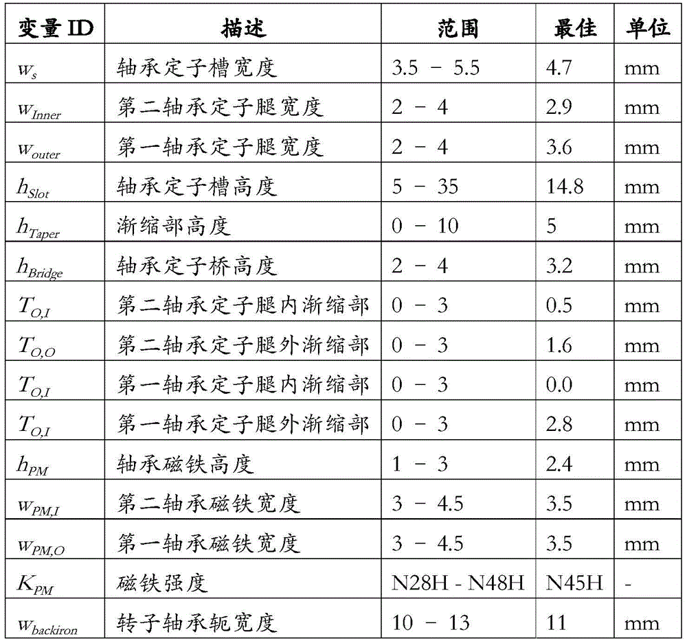
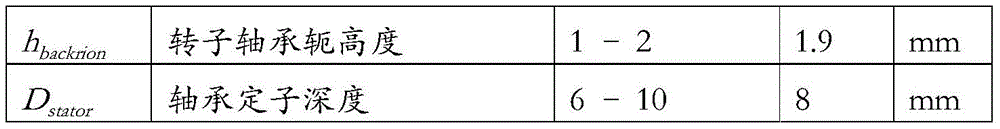
因此,从上面将认识到,可以通过轴承中的磁路元件的设计来控制径向刚度与轴向刚度的比率。尤其是在气隙附近渐缩的高渗透性材料可以用来增加刚度比,而永磁体的位置和几何形状可以用来影响刚度比和轴承产生的被动轴向力。如果这些变化增加了径向运动的磁阻的变化和/或减小了轴向运动的磁阻的变化,则可以通过这些变化来改善刚度比。Thus, it will be appreciated from the above that the ratio of radial stiffness to axial stiffness can be controlled by the design of the magnetic circuit elements in the bearing. In particular, highly permeable materials tapered near the air gap can be used to increase the stiffness ratio, while the location and geometry of the permanent magnets can be used to influence the stiffness ratio and the passive axial force generated by the bearing. If these changes increase the change in reluctance for radial movement and/or reduce the change in reluctance for axial movement, the stiffness ratio can be improved by these changes.
图9B示出了马达和磁性轴承吸引力之间的净力差。在该示例中的轴向系统刚度在平衡点为37N/mm。在实践中,心脏泵通常具有的轴向系统刚度至少为如下之一:至少10N/mm、至少20N/mm、至少30N/mm、少于60N/mm、少于50N/mm、约10-60N/mm、约25-50N/mm、约15-25N/mm、约30-40N/mm和约35-40N/mm。在该示例中,几乎所有的径向系统刚度都是由轴承的径向刚度产生的,而马达系统的贡献却很小,但是在其他配置中,马达会有更大、更重要的贡献。心脏泵径向系统刚度至少为如下之一:0.5N/mm至11N/mm,0.5N/mm至1.5N/mm,1.5N/mm至3.0N/mm,3N/mm至6N/mm和介于6N/mm和11N/mm之间。Figure 9B shows the net force difference between the attractive force of the motor and the magnetic bearing. The axial system stiffness in this example is 37 N/mm at equilibrium. In practice, cardiac pumps typically have an axial system stiffness of at least one of: at least 10 N/mm, at least 20 N/mm, at least 30 N/mm, less than 60 N/mm, less than 50 N/mm, about 10-60 N /mm, about 25-50 N/mm, about 15-25 N/mm, about 30-40 N/mm and about 35-40 N/mm. In this example, almost all of the radial system stiffness is due to the radial stiffness of the bearing, with a small contribution from the motor system, but in other configurations the motor has a larger and more significant contribution. Heart pump radial system stiffness is at least one of the following: 0.5N/mm to 11N/mm, 0.5N/mm to 1.5N/mm, 1.5N/mm to 3.0N/mm, 3N/mm to 6N/mm and medium between 6N/mm and 11N/mm.
组合轭combination yoke
在上面的示例中,转子驱动器轭135和转子轴承轭146被标识为单独的元件。然而,实际上,转子驱动器轭135和轴承轭146可组合成单个整体式环形元件。组合的转子驱动器和轴承轭的厚度、设计和材料可以从其独立的独立设计中进行修改,以提高组合系统的性能。In the above example, the
例如,当转子驱动器和轴承轭135、146在物理上充分磁分离时,马达和磁性轴承系统产生的力分别作用在转子轭元件上,需要将转子驱动器和轴承轭135、146机械连接,以传递力并平衡力。转子驱动器和轴承轭135、146的组合将两个磁性系统之间的力连接在一起,从而简化了转子的设计。单个转子驱动器和轴承轭的组合制造和组装可以减少公差叠加,从而改善转子的平衡和悬浮性能。通过组合磁轭的设计,例如厚度和材料的选择,可以使通过组合的转子驱动器装置和轴承轭的马达与磁性轴承磁通之间的交叉耦合最小化。For example, when the rotor drive and bearing
高纯铁由于其高的磁通饱和度而经常用于转子驱动器和轴承轭135、146的构造中。其他材料,例如钴铁钒合金(Hiperco 50A)可以提供更高的磁通饱和度,因此特别适用于此应用,因为它们可以减少转子磁轭中所需的材料量,因此可以减少转子的厚度和整个设备的厚度。对于恒定直径的这种高度减小还可以改善转子的动力。组合的转子驱动器和轴承轭可由多种不同的材料制成,这些材料具有不同的磁性能,以形成具有不均匀磁导率的轭。具有低磁饱和度的材料可以在组合的转子驱动器和轴承轭中使用,以通过增加磁阻对两侧之间流动的磁通量的路径来最小化两个磁系统之间的交叉耦合。High purity iron is often used in the construction of rotor drives and bearing
在线传感器再校准Online sensor recalibration
磁性轴承致动器在各种轴向气隙下的已知力特性可用于验证转子的轴向位置。在给定的低频下,磁性轴承致动器电流的小正弦扰动将在转子中产生运动,该运动是电流刚度和轴向位置刚度的函数。准确了解电流和轴向位置刚度的变化与气隙的关系,可以根据所测得的扰动响应估算气隙。由于扰动很小,因此可以在设备运行时进行此测量。可以将通过在线摄动方法获得的有关气隙的信息与从位置传感器接收到的位置数据进行比较,以确保由于磁悬浮轴承系统的变化(例如传感器校准或永磁体强度)而导致系统性能没有变化。Known force characteristics of magnetic bearing actuators at various axial air gaps can be used to verify the axial position of the rotor. At a given low frequency, a small sinusoidal perturbation of the magnetic bearing actuator current will generate motion in the rotor that is a function of current stiffness and axial position stiffness. Knowing exactly the change in current and axial position stiffness as a function of the air gap allows the air gap to be estimated from the measured perturbation response. Since the perturbation is small, this measurement can be made while the device is running. The information about the air gap obtained by the online perturbation method can be compared with the position data received from the position sensor to ensure that there is no change in system performance due to changes in the magnetic bearing system (such as sensor calibration or permanent magnet strength).
上述配置可以在多种情况下和在不同的泵构造中使用。例如,下面的情况可以使用此功能:当使用一台或两台泵提供帮助或更换左或右心室时;包含在TAH中,当两个旋转泵可以完全替代天然心脏时;在LVAD/RVAD中,当使用单个旋转泵为左心室或右心室提供帮助时;或者在BiVAD中,当两个旋转泵为左心室和右心室提供帮助时。The above configuration can be used in a variety of situations and in different pump configurations. For example, this feature can be used: when one or two pumps are used to assist or replace the left or right ventricle; included in TAH, when two rotary pumps can completely replace the natural heart; in LVAD/RVAD , when a single rotary pump is used to assist the left or right ventricle; or in BiVAD, when two rotary pumps assist the left and right ventricles.
现在将参照图17A至图17F描述单个VAD心脏泵的示例。An example of a single VAD heart pump will now be described with reference to Figures 17A-17F.
在该示例中,心脏泵1700包含限定腔体1715的外壳1710。外壳可以是任何合适的形式,但是通常包含主体以及连接到主体的左右端盖。外壳可以由任何合适的生物相容性材料制成,并且可以由钛、聚合物等制成。In this example, the
外壳1710包含入口1711和出口1712,入口1711用于连接到左心房/肺静脉或右心房/静脉腔,或左心室或右心室,出口1712用于连接到主动脉或肺动脉。
心脏泵1700包含设置在腔体1715内的叶轮1720。叶轮1720包含转子1721,其上安装有叶片,用于在叶轮1720旋转时将流体从入口1711推向出口1712。在该示例中,由于心脏泵1700是单个心室辅助设备,因此叶轮包括用于将流体从入口1711推向出口1712的单组叶片1722。在该示例中,叶片1722具有特定的构造,但是应当理解,可以使用其他合适的叶片构造。叶轮还可包括穿过其延伸的孔1724,以允许血液在叶轮的后表面周围流动,从而防止心脏泵内血液的停滞和凝结。此外,在该区域使用磁性轴承可以使血间隙超过200-300μm,这不仅可以减少剪切应力,从而减少红细胞的溶解,而且可以提高冲刷流的速度,这比所预期的在流体动力轴承产生的间隙中的速度要高。
心脏泵1700还包含驱动器1730,该驱动器使叶轮1720在腔体1715内旋转。驱动器1730可以是任何合适的形式,但是通常包含多个线圈1731,每个线圈缠绕在相应的定子1732上,并由安装件1733支承,从而使驱动器1730可以联接到外壳1710。该驱动器与安装在转子1721中的磁性材料1734协作,其中磁性材料为配置在转子1721的外周边缘附近的多个周向间隔的永久驱动器磁体的形式。在一个示例中,线圈1731和定子1732是楔形的并且围绕安装件1733在圆周上间隔开,以便提供与转子1721中的驱动器磁体1734轴向对准的十二个电磁体,从而最大化转子1721中的磁体和驱动器1730之间的磁耦合程度。The
心脏泵1700还可包括磁性轴承1740,该磁性轴承1740包含至少一个轴承线圈1741,该轴承线圈1741控制叶轮在腔体1715内的轴向位置。在一个特定的例子中,在图17E中更详细地示出,磁性轴承包含三个轴承线圈1741,每个轴承线圈安装在相应的U形定子1742的第一臂1742.1上,第二臂1742.2位于第一臂1742.1的径向内侧。定子1742被安装到支架1743或与支架1743一体形成,并且围绕外壳在圆周方向上间隔开170°,以便第一臂1742.1和第二臂1742.2与相应的磁性材料(例如叶轮1720内的轴承磁体1744,1745)对准,从而可以控制叶轮1720的轴向位置。The
在一个特定的示例中,轴承转子组件包含:铁磁芯靶1744,其安装在转子中,靠近转子1721的外周边缘,以及永磁性轴承或铁磁材料1745,其沿径向安装在第一铁磁芯靶1744的内侧,从而铁磁芯靶和轴承磁铁1744、1745分别与定子1742的各臂1742.1、1742.2对准。可以用第二永磁体代替铁磁芯靶。然而,可能不需要使用磁性轴承,而可以用静态物理轴承或流体动力轴承等代替。In one particular example, the bearing rotor assembly includes a
在该示例中,如图17B所示,驱动器1730和磁性轴承1740安装在外壳1710的相对端,从而驱动器和轴承1730、1740被设置在转子1721的相对表面附近。在当前示例中,驱动器1730邻近叶轮1720的包括叶片的侧面安装,以使转子、叶片和外壳之间的血液间隙最大化。也就是说,只有叶片尖端更靠近外壳,而该血间隙仍可以在200-300μm的数量级。另外,轴承和驱动器被配置成使得驱动器1730和叶轮1720之间以及磁性轴承1740和叶轮1720之间的固有磁力以及叶轮1720上的液压力在正常流动条件下在腔体内限定平衡位置。这最小化了在标称流动条件下将叶轮1720保持在腔体内的位置所需的轴承功率。In this example, as shown in FIG. 17B , the
应当理解,在先前的示例中,该设备可以进一步包括控制器,并且其他方面的功能如前所述,因此将不进行进一步详细描述。It should be understood that in the previous example, the device may further include a controller, and other aspects of the function are as previously described, and thus will not be described in further detail.
另外,上述配置可用于具有不同轴承类型的一个或多个组合的泵,例如,接触轴承、被动磁性轴承和流体动力轴承。这些轴承类型中的每一种都对其工作有轴向力的要求,并且可以从上述设计概念中受益。Additionally, the above-described configuration may be used in pumps having one or more combinations of different bearing types, such as contact bearings, passive magnetic bearings, and hydrodynamic bearings. Each of these bearing types has axial force requirements for its operation and can benefit from the design concepts described above.
心脏泵可以与控制器和控制过程配合使用,该控制过程使用主动磁性轴承和零功率控制器,该控制器响应磁性轴承电流的变化来控制转子的位置,或者使用基于叶轮位置的速度控制,例如,响应于流量/轴承操作中的扰动,以提供对流量的附加控制程度。Heart pumps can be used in conjunction with a controller and a control process that uses active magnetic bearings and a zero-power controller that controls rotor position in response to changes in magnetic bearing current, or speed control based on impeller position, such as , in response to disturbances in flow/bearing operation to provide an additional degree of control over flow.
例如,可以将上述心脏泵配置为在轴向主动磁性轴承出现故障时使用回落式流体动力轴承运行,现在将参考图18A至18C对此示例进行详细说明。For example, the heart pump described above may be configured to operate using a drop-back hydrodynamic bearing in the event of a failure of the axial active magnetic bearing, an example of which will now be described in detail with reference to Figures 18A-18C.
尤其是,图18A至18C示出了由外壳1810限定的叶轮腔体1811,其中叶轮1820定位在其中。在腔体的左端1811.1处,与左端壁1810.1相邻地设置驱动器1830,而在腔体的右端1811.2上,在与右端壁1810.2相邻的位置上,设置有磁性轴承1840,在一个示例中该腔体的长度约为600μm。因此,应当理解,该配置通常类似于以上参考图1A至3D所描述的配置。应当注意,术语腔体的左端和右端是指在附图中定向的左和右,但也指泵的相应功能,腔体的左侧用于提供左心室功能,腔体的右侧起到提供右心室功能的作用。In particular, Figures 18A-18C illustrate the
可以将腔体划分为多个区域,包括正常工作区域1881,左右缓冲区域1882、1883和左右末端区域1884、1885。The cavity can be divided into a plurality of regions, including a
图18A中示出了与虚线1887一致的在没有液压力的情况下的最小功率平衡位置。在该位置,在没有液压力的情况下,驱动力和轴承的吸引力平衡,使得仅需要少量的轴承电流即可平衡较小的干扰力并将叶轮1820保持在平衡位置1887。The minimum power balance position in the absence of hydraulic pressure is shown in Figure 18A, consistent with dashed
实际上,在腔体中存在液压力的正常工作条件下,叶轮1820设置在腔体1886的几何中心附近,通常在工作范围区域1881内。在这种情况下,驱动器和轴承的吸引力以及液压力一起达到平衡,因此在理论上不需要轴承电流来将叶轮1820保持在平衡位置1886。In fact, under normal operating conditions where hydraulic forces are present in the cavity, the
然而,应当理解,叶轮1820将根据特定的液压力在腔体内向左或向右移动,在正常情况下,该运动通常被限制在工作区域1881内。It should be understood, however, that the
在发生磁体轴承故障的情况下,叶轮1820通常将分别由于驱动器1830或轴承1840的磁性吸引而被吸引到腔体1811的左端1811.1或右端1811.2,这取决于各种因素,例如叶轮1820的位置和故障时的主要液压条件。In the event of a magnet bearing failure, the
在如图18C所示的情况中,如果叶轮被吸引到腔体左端1811.1,则通过叶轮1820的适当构造,叶轮叶片的上表面可以用作流体动力轴承,从而允许叶轮1820继续旋转而不会物理地接合外壳1810。在这方面,流体动力轴承是由于左叶轮叶片的上表面与左端壁1810.1之间形成薄的流体膜而产生的,这是由于叶轮叶片具有足够大的表面积和倾斜表面而引起流体积聚在叶片表面和左端壁1810.1之间。In the situation shown in Figure 18C, if the impeller is attracted to the left end 1811.1 of the cavity, with proper configuration of the
图19A至19C显示了叶轮用作流体动力轴承的配置示例。19A to 19C show configuration examples in which the impeller is used as the hydrodynamic bearing.
在该示例中,叶轮包括转子1920,转子1920上安装有多个叶片1921。在该示例中,显示了六个叶片,尽管实际上可以使用三个以上的任何叶片,通常可以使用小于10个的叶片。In this example, the impeller includes a
每个叶片1921包含斜坡1921.1和垫1922.2。斜坡倾斜,使得当叶轮沿箭头1900的方向旋转时,一些流体沿斜坡被引导,如箭头1901所示,以在叶轮叶片和端壁1810.1之间流动,从而产生了流体动力轴承效应。垫1921.2形成为平行于端壁1810.1的平坦部段,其起到提供流动阻力并减少通过斜坡1921.1的泄漏的作用,从而放大了流体动力轴承效果。斜坡长度LR与垫长度Lp之比应当在0.1到0.3之间,通常为0.2。Each
如图19C所示,有七个主要参数决定了最佳的流体动力轴承设计,其中显示了三种不同的设计。这些参数包含叶轮叶片RI的内半径、垫RO的外半径、平垫RP的内半径、平垫LP的长度、坡道的高度、坡道LR的长度、垫的数量和介质的表面速度。There are seven main parameters that determine the optimal hydrodynamic bearing design, as shown in Figure 19C, of which three different designs are shown. These parameters include the inner radius of the impeller blade RI , the outer radius of the pads RO , the inner radius of the flat pads RP , the length of the flat pads LP , the height of the ramp, the length of the ramp LR , the number of pads and the medium surface speed.
在一个示例中,垫的外半径取决于叶轮直径,并固定在25mm。平垫的内半径、叶片的总长度、表面速度和垫的数量是根据流体动轴承力所要求的升力来确定的,而叶片的内半径会影响左叶轮的血流动力学,因为它与右叶轮一起用作TAH泵。In one example, the outer radius of the pad depends on the impeller diameter and is fixed at 25mm. The inner radius of the flat pads, the overall length of the vanes, the surface velocity and the number of pads are determined from the lift required by the hydrodynamic bearing force, while the inner radius of the vanes affects the left impeller hemodynamics because it is different from the right impeller. The impellers work together as a TAH pump.
最终设计参数是平垫与斜坡的长度比(10-30%)和平垫前缘相对于径向中心线与叶轮中心的角度(0-10deg),这会将平垫的内半径更改为18-20mm。The final design parameters are the length ratio of the flat pad to the ramp (10-30%) The angle of the leading edge of the flat pad relative to the radial centerline and the center of the impeller (0-10deg), this will change the inner radius of the flat pad to 18- 20mm.
在图19C所示的示例中,设计之间变化的主要参数是平垫前缘的角度,这反过来允许将更多的平垫用作流体动力轴承,从而增加了力的产生,但没有使用叶轮叶片的整个长度,这会产生额外的剪切力,但由于在该内半径处的斜坡/垫区域的长度较短,因此不会在内径处增加力能力。In the example shown in Figure 19C, the main parameter that varies between designs is the angle of the leading edge of the flat pad, which in turn allows more of the flat pad to be used as a hydrodynamic bearing, increasing force production, but no use of The entire length of the impeller blade, which creates additional shear forces, but does not increase the force capacity at the inner radius due to the shorter length of the ramp/pad area at that inner radius.
在一个示例中,所述平垫的内半径为16mm至22mm之间且在18mm至20mm之间的至少其中之一,其长度至少为以下之一:1mm至5mm;2mm至4mm;以及,大约3mm;斜坡的长度至少为以下之一:在5mm至15mm之间;在8mm至12mm之间;以及,大约10mm并且高度至少在以下之一:在0.02mm至0.1mm之间;在0.04mm至0.08mm之间;以及,约0.06mm。叶片通常具有10mm至20mm之间,12mm至18mm之间,14mm至16mm之间,以及大约15mm中的至少一个的内半径,以及至少为以下之一的外半径:介于20mm至30mm之间;22mm至28mm之间;24mm至26mm之间;以及,约25mm。In one example, the flat pad has an inner radius of at least one of between 16mm and 22mm and between 18mm and 20mm, and a length of at least one of: 1mm to 5mm; 2mm to 4mm; and, approximately 3mm; the length of the slope is at least one of the following: between 5mm and 15mm; between 8mm and 12mm; and, approximately 10mm and the height is at least one of the following: between 0.02mm and 0.1mm; between 0.04mm and between 0.08mm; and, about 0.06mm. The blades typically have an inner radius of at least one of between 10mm and 20mm, between 12mm and 18mm, between 14mm and 16mm, and about 15mm, and an outer radius of at least one of: between 20mm and 30mm; Between 22mm and 28mm; between 24mm and 26mm; and, approximately 25mm.
下表8中显示了典型设计参数的示例:Examples of typical design parameters are shown in Table 8 below:
表8Table 8
血流动力学方面,六叶片叶轮通过两个抽气腔体产生合适的左右德尔塔(delta)压力差比,从而在人体应用方面表现出色。In terms of hemodynamics, the six-blade impeller produces a suitable left-right delta pressure ratio through the two extraction chambers, thus excelling in human applications.
图19D和19E分别显示了左右侧泵在悬浮模式下各种速度下的性能HQ曲线示例。Figures 19D and 19E show examples of performance HQ curves for the left and right side pumps at various speeds in suspension mode, respectively.
这些显示了在工作速度范围内所需的流率,并进一步显示了所需的左右压力匹配比为3.5:1。These show the desired flow rate over the operating speed range and further show that the desired left-to-right pressure matching ratio is 3.5:1.
在任何情况下,轴承的作用是向腔体右端1811.2施加力,有效地推动叶轮1820远离左端壁1810.1并抵消驱动器磁体产生的磁力,从而将叶轮保持悬浮在空腔1811内。In any event, the role of the bearing is to apply a force to the right end 1811.2 of the cavity, effectively pushing the
由流体动力轴承产生的悬浮力的示例在图20A中示出。这突显出,随着叶轮转速的增加,轴承产生的净液压力增加,叶轮进一步远离左端壁1810.1,如图所示。An example of the levitation force generated by a hydrodynamic bearing is shown in Figure 20A. This highlights that as the rotational speed of the impeller increases, the net hydraulic pressure generated by the bearing increases, the impeller moving further away from the left end wall 1810.1 as shown.
相反,如果叶轮移动到腔体1811的右端1811.2,则由于右叶轮叶片的上表面面积通常要小得多,它们不会提供流体动力轴承作用,叶轮将与外壳1810的右端壁1810.2接触,从而可能导致泵损坏,并降低效率。因此,期望确保如果磁体轴承失效,则在转子移动到腔体的右侧的情况下,叶轮1820可以移动到腔体的左侧,从而允许流体动力轴承能够工作。Conversely, if the impeller moves to the right end 1811.2 of the
液压力和磁力的综合作用如图20B所示。The combined effect of hydraulic pressure and magnetic force is shown in Figure 20B.
叶轮的平衡点将与零净力线重合。曲线显示了在恒定转速和SVR和PVR值的条件下的典型作用力,对应于对象在2001感到压力而导致系统性高血压,在2002休息和在2003运动。The balance point of the impeller will coincide with the zero net force line. The curves show typical applied forces under conditions of constant rotational speed and SVR and PVR values, corresponding to the subject feeling stressed leading to systemic hypertension in 2001, resting in 2002 and exercising in 2003.
当叶轮位于腔体左侧1811.1(位置<-0.3mm)时,当流体动力轴承产生的力占主导地位时,净力最初较高,并且轴向指向轴承。当叶轮移向腔体1811的中心(位置=±0.2mm)时,净力最初为负,表示朝驱动器1830的磁吸引力,然后当叶轮1820接近磁性轴承1840(位置>0.2mm)时,净力再朝向轴承1840。When the impeller is located 1811.1 to the left of the cavity (position <-0.3mm), the net force is initially high and directed axially towards the bearing as the force from the hydrodynamic bearing dominates. As the impeller moves towards the center of the cavity 1811 (position = ±0.2mm), the net force is initially negative, representing a magnetic attraction towards the
在正常的泵操作情况下,控制器150操作磁性轴承1840以最小化磁性轴承1840保持叶轮1820在腔体1811中的位置所需的功率。为此,控制器150使用轴承将叶轮1820放置在腔体1811内位于曲线(如分别在2011、2012、2013所示的压力、休息和运动时的曲线)的右侧部分与零轴的交点表示的点处。相反,如果磁体轴承发生故障,则希望将叶轮移动至零轴的左相交点,如在2014大体所示,此时叶轮仅由流体动力轴承支承。Under normal pump operating conditions, the
在磁性轴承失效的情况下,取决于叶轮1820在腔体1811内的位置以及当前的血液动力学状况,叶轮1820可移动到腔体的左端或右端1811.1、1811.2。例如,可以看出,在运动条件下,叶轮1820通常位于腔体右端1811.2,因此,再加上腔体左端1811.1中更大的流体压力,意味着如果轴承1840发生故障,则叶轮更可能被吸引到轴承1840上。在叶轮1820移动到腔体右端1811.2的情况下,需要采取行动将叶轮1820移动到腔体左端1811.1,以使得流体动力轴承正确地起作用。In the event of a magnetic bearing failure, depending on the position of the
即使当叶轮1820移动到腔体左端1811.1时,例如由于对外壳1810的物理冲击而产生的轴向力也会导致叶轮1820移动到腔体右端1811.2。所需的力由图20B中的箭头所示,并且对应于所示的压力、休息和运动条件的每一个的轴向力分别约为2、4或8牛顿。Even when the
此外,如果叶轮一直移动到腔体的右侧,则需要15牛顿的力才能将叶轮移回到腔体的左侧。Also, if the impeller moves all the way to the right side of the cavity, it will take 15 Newtons of force to move the impeller back to the left side of the cavity.
基于此,将期望产生朝向驱动器1830的轴向力,以将叶轮1820移动到腔体左端1811.1和/或减少外力导致叶轮1820移位到腔体右端1811.2的风险。在一个示例中,这可以通过对驱动器1830的适当控制,特别是通过对驱动器产生的磁场的适当配置,以及使用这些磁场来产生轴向吸引力或排斥力来实现。现在将参考图21A至21C描述其示例。Based on this, it would be desirable to generate an axial force towards the
对于这些示例,该驱动器包括多个周向间隔开的永磁驱动器磁体2134,该永磁驱动器磁体2134安装安装在叶轮内的软铁转子驱动器轭2135上。该驱动器还包括多个在腔体的左端附近安装的沿圆周方向隔开的驱动器线圈2131,每个线圈2131缠绕在驱动器定子芯2132的相应驱动器定子极2132.1上,并与驱动器磁体2134基本径向对准。For these examples, the drive includes a plurality of circumferentially spaced permanent
在图21A的示例中,线圈2131被控制使得相邻的线圈产生相对于驱动器磁体偏移的相反磁场,从而以一定角度吸引和排斥驱动器磁体2134,从而产生旋转转矩。相反,在图21B和21C的示例中,驱动器线圈2131产生与驱动器磁体2134对准的场,但是具有相等或相反的极性以分别产生排斥力或吸引力。In the example of Figure 21A, the
对于其余的描述,朝向驱动器的吸引力称为正轴向力,而排斥力称为负力。此外,术语“旋转电流和轴向电流”用于描述当应用于驱动器时产生旋转力或轴向力的电流。For the rest of the description, the attractive force towards the drive is called the positive axial force, and the repulsive force is called the negative force. Furthermore, the terms "rotating current and axial current" are used to describe currents that generate a rotational or axial force when applied to a drive.
无论如何,应当理解,控制器通过对驱动信号发生器137的适当控制,可以控制驱动器1830,从而产生朝向驱动器1830的正轴向力。这可用于允许叶轮1820从腔体右端1811.2移动到腔体左端1811.1,而无需磁性轴承1840的干预,或用于增加朝向驱动器1830的轴向力,从而降低叶轮1820在外力的作用下移动到腔体右端1811.2的可能性。In any event, it should be understood that the controller, through appropriate control of the
因此,控制器可以控制驱动器以产生轴向吸引力,从而在磁性轴承发生故障的情况下使用流体动力轴承运行时在腔体内移动叶轮和/或增加抗冲击性。为此,当磁性轴承发生故障时,控制器要么检测磁性轴承的故障,要么检测叶轮向腔体右侧的运动,然后响应于该检测,控制驱动器以产生轴向吸引力。控制器基于指示磁性轴承使用的电流的轴承指示器,指示驱动装置使用的电流的驱动器指示器或传感器信号(例如位置传感器信号)中的至少一个来检测磁性轴承的故障或叶轮的运动。Thus, the controller can control the drive to create an axial attraction force to move the impeller within the cavity and/or increase shock resistance when operating with the hydrodynamic bearing in the event of a magnetic bearing failure. To this end, when the magnetic bearing fails, the controller either detects the failure of the magnetic bearing, or detects the movement of the impeller to the right of the cavity, and then, in response to this detection, controls the drive to generate an axial attraction force. The controller detects failure of the magnetic bearing or movement of the impeller based on at least one of a bearing indicator indicative of current used by the magnetic bearing, a drive indicator indicative of current used by the drive, or a sensor signal (eg, a position sensor signal).
现在将参照图22A至22D描述控制器在轴承故障后致动流体动力轴承的操作示例。An example of the operation of the controller to actuate the hydrodynamic bearing after bearing failure will now be described with reference to Figures 22A to 22D.
在该示例中,在时间t<0时,泵正常工作,并且轴承1840使用相对恒定的最小电流2211运转,叶轮1820略微朝向腔体左端1811.1定位在工作区域1881中,如2221所示。驱动器使用恒定的驱动器旋转电流2241.1和零轴向电流2241.2以恒定的转速2231运行。In this example, at time t<0, the pump is operating normally and the
在时间t=0,出现悬浮故障并且磁性轴承发生故障,这由轴承电流2212的瞬时增加来表示。恒定电流2213被注入到轴承1840中,以试图使轴承再次运行,当轴承无响应时,在2214所示的预定时间之后(在这种情况下为0.3秒),该恒定电流被停用。At time t=0, a levitation fault occurs and the magnetic bearing fails, which is represented by a momentary increase in bearing current 2212. A constant current 2213 is injected into the
如本示例所示,当轴承发生故障时,叶轮1820在2222处移动到腔体右端1811.2,由于驱动器1830中的负载变化而导致叶轮转速下降2232。尤其是,由叶轮1820和右端壁1810.2之间的接触引起的摩擦增加导致叶轮瞬时减慢,直到旋转电流2242.1增加以抵消叶轮1820与右端壁1810.2之间的摩擦。将理解的是,这允许控制器150确定已经在叶轮腔的右侧发生了触地。As shown in this example, when the bearing fails, the
作为结果,马达被控制以产生较大的正轴向电流2242.2,这导致叶轮1820从右端壁1810.2升起并向左端壁1810.1移动。随着摩擦负载的升高,这会导致转速2233相应跳变,从而使驱动旋转电流返回到其原始值2243.1,以保持叶轮转速。从这一点开始,叶轮不再是磁悬浮的,而是基于流体动力轴承的运行而悬浮,如叶轮位置2223所示。As a result, the motor is controlled to generate a larger positive axial current 2242.2, which causes the
因此,这描述了用于将叶轮1820从腔体右端1811.2移至腔体左端1811.1的装置的操作。Thus, this describes the operation of the means for moving the
一旦进入腔体左端1811.1,驱动轴向力可用于帮助防止叶轮移回到腔体右端1811.2,图23显示了此示例,该图突出显示了受压对象的净力曲线2301。通过驱动器轴施加正轴向电流会使曲线2302向下移动,从而将叶轮从流体动力轴承移到外壳右侧的所需净力从2牛顿增加到7牛顿,如箭头所示。应当理解,轴向驱动力的进一步增加可用来进一步增加这一点。Once inside the cavity left end 1811.1, the drive axial force can be used to help prevent the impeller from moving back to the cavity right end 1811.2, an example of which is shown in Figure 23, which highlights the
图24A示出轴承刚度的影响,突出显示了对于更高的轴承刚度,为了使叶轮从外壳的左侧移动到右侧,所需的力增加了,如箭头所示,因此表明较高的固有轴向刚度是有益的。这也将有助于增加径向刚度,从而减少叶轮由于外部作用力而接触外壳的机会。Figure 24A shows the effect of bearing stiffness, highlighting that for higher bearing stiffness, the force required to move the impeller from the left side to the right side of the housing increases, as indicated by the arrows, thus indicating higher inherent Axial stiffness is beneficial. This will also help increase radial stiffness, thereby reducing the chance of the impeller touching the casing due to external forces.
可以实施的另一选择是减小左端壁1810.1与驱动器1830的偏移,这可以进一步帮助进一步增加为了移出叶轮1820所需的力,如图24B中的箭头所示。Another option that can be implemented is to reduce the offset of the left end wall 1810.1 from the
从上面将认识到,驱动器电流的改变可用于调节轴承刚度。类似的,也可以使用轴承电流,这在控制径向刚度时尤其有用。It will be appreciated from the above that changes in driver current can be used to adjust bearing stiffness. Similarly, bearing currents can also be used, which is especially useful when controlling radial stiffness.
转子响应于径向激励力(例如转子不平衡)的径向运动或振动随径向刚度、径向阻尼、激励频率和转子质量而变化。振动响应的振幅在共振频率处达到峰值,这可能导致转子响应于激励力而呈现出较大的振动振幅,并且在某些情况下,如果阻尼和刚度不足,则可能导致转子触地或变得不稳定。The radial motion or vibration of the rotor in response to radial excitation forces (eg, rotor unbalance) varies with radial stiffness, radial damping, excitation frequency, and rotor mass. The amplitude of the vibrational response peaks at the resonant frequency, which can cause the rotor to exhibit large vibrational amplitudes in response to the excitation force, and in some cases, if damping and stiffness are insufficient, the rotor can touch the ground or become unstable.
在某些情况下,不希望在共振频率或共振频率附近工作,应该避免。因此,如果需要以共振频率下的转子速度运行,并且不能通过改变刚度、阻尼或转子质量来改变共振频率,通过用偏置电流改变刚度可以暂时改变系统刚度以移动共振频率。In some cases, operation at or near the resonant frequency is undesirable and should be avoided. Therefore, if it is desired to operate at the rotor speed at the resonant frequency, and the resonant frequency cannot be changed by changing the stiffness, damping, or rotor mass, the system stiffness can be temporarily changed to move the resonant frequency by changing the stiffness with a bias current.
为了减小转子在接近共振频率运行时的振动,可以暂时增加径向刚度,从而增加共振频率。To reduce the vibration of the rotor when operating close to the resonant frequency, the radial stiffness can be temporarily increased, thereby increasing the resonant frequency.
实现此目的的一种方法是向磁性轴承线圈添加额外的电流,以增加其力和刚度,同时保持转子位置。刚度的增加将增加系统的共振频率使其高于其典型值,并允许在原始共振频率下以减小的振动进行操作,并且图25A示出了当转子保持在恒定位置并且磁性轴承偏置电流的量增加时来自磁性轴承的径向刚度增加的一个示例。恒定位置和磁性轴承偏置电流的量如。图25B示出了当转子保持在恒定位置并磁性轴承偏置电流量增加时这对无阻尼径向共振频率的影响。图25C显示了驱动器轴向电流增加的类似变化。One way to achieve this is to add extra current to the magnetic bearing coils to increase their force and stiffness while maintaining rotor position. The increase in stiffness will increase the resonant frequency of the system above its typical value and allow operation with reduced vibration at the original resonant frequency, and Figure 25A shows when the rotor is held at a constant position and the magnetic bearing bias current An example of the increase in radial stiffness from a magnetic bearing when the amount of . Constant position and amount of magnetic bearing bias current eg. Figure 25B shows the effect of this on the undamped radial resonant frequency when the rotor is held at a constant position and the amount of magnetic bearing bias current is increased. Figure 25C shows a similar change for the increase in the axial current of the driver.
除了增加刚度外,偏置电流还将提供一种吸引力,该吸引力可以通过经由直流增加马达的吸引力来抵消。暂时增加刚度的另一种方法也可以通过将转子位置移向磁性轴承,同时保持正常的偏置电流量来实现。In addition to increasing stiffness, the bias current will provide an attractive force that can be counteracted by increasing the attractive force of the motor via DC. Another way to temporarily increase stiffness can also be achieved by moving the rotor position towards the magnetic bearings while maintaining the normal amount of bias current.
这可以通过利用控制器在上述系统中实现。当马达控制器识别出它正在接近一个已知的共振频率运行时,可以通过增加马达直流电流来增加附加的马达轴向吸引力,从而使轴向悬浮控制器将转子移向磁性轴承,从而增加径向刚度。This can be achieved in the system described above by using a controller. When the motor controller recognizes that it is operating near a known resonant frequency, additional motor axial attraction can be added by increasing the motor DC current, causing the axial suspension controller to move the rotor towards the magnetic bearing, increasing the Radial stiffness.
尽管上述示例集中于将流体动力轴承用作磁悬浮叶轮的故障模式,应当理解,这不是必须的,并且可替代地,流体动力轴承可以用作磁性轴承的替代。Although the above examples focus on the failure mode of using a hydrodynamic bearing as a magnetically levitated impeller, it should be understood that this is not required, and alternatively, a hydrodynamic bearing could be used as a replacement for a magnetic bearing.
在示例中,心脏泵可以包含限定腔体的外壳,该腔体包含至少一个与腔体的轴线对准的入口和设置在腔体的周向外壁中的至少一个出口。可以在腔体内设置叶轮,该叶轮包含转子和安装在转子上的叶片,用于将流体从入口径向向外推动到出口。然后提供用于使叶轮在腔体中旋转的驱动器,该驱动器包含:安装在转子的第一面内并邻近转子的第一面的多个周向间隔开的永久驱动器磁体以及,多个在圆周方向上间隔开的驱动器线圈,安装在外壳内,靠近腔体的第一端。在该示例中,叶轮的叶片与外壳的第一端配合以定义流体动力轴承,从而使叶轮悬浮在腔体内。In an example, a heart pump may include a housing defining a cavity including at least one inlet aligned with an axis of the cavity and at least one outlet disposed in a peripheral outer wall of the cavity. An impeller may be provided within the cavity, the impeller comprising a rotor and vanes mounted on the rotor for urging fluid radially outward from the inlet to the outlet. A drive is then provided for rotating the impeller in the cavity, the drive comprising: a plurality of circumferentially spaced permanent drive magnets mounted in and adjacent to the first face of the rotor and a plurality of circumferentially spaced drive magnets Directionally spaced driver coils are mounted within the housing proximate the first end of the cavity. In this example, the blades of the impeller cooperate with the first end of the housing to define a hydrodynamic bearing, thereby suspending the impeller within the cavity.
现在将参考图26A至26D描述许多线圈绕组配置的示例。Examples of a number of coil winding configurations will now be described with reference to Figures 26A to 26D.
在图26A的示例中,该驱动器包括十二个独立的线圈,为了提供三相驱动器而运行。尤其是,对线圈U1,U2;U3,U4;V1,V2;V3,V4;以及W1,W2;W3,W4的成对线圈进行顺序控制,以提供单三相驱动器配置。实际上,这是通过将每个相位的驱动信号施加到串联的相应线圈对来实现的,如图26B所示。In the example of Figure 26A, the driver includes twelve separate coils operating to provide a three-phase driver. In particular, pairs of coils U1, U2; U3, U4; V1, V2; V3, V4; and W1, W2; W3, W4 are sequentially controlled to provide a single three-phase drive configuration. In practice, this is achieved by applying the drive signal for each phase to the corresponding coil pair in series, as shown in Figure 26B.
相反,在图26C的配置中,使用了相同的物理十二个线圈配置,控制了相对的线圈对,以提供双三相配置。具体地,线圈U1,U2;V1,V2;W1,W2提供第一三相驱动器,而线圈X1,X2;Y1,Y2;Z1,Z2形成第二三相驱动器。使用图26C和26D中所示的双驱动器配置具有许多好处,包括例如在其中一个驱动器发生故障的情况下提供故障冗余。In contrast, in the configuration of Figure 26C, the same physical twelve coil configuration is used, with opposing pairs of coils being controlled to provide a dual three-phase configuration. In particular, coils U1, U2; V1, V2; W1, W2 provide a first three-phase driver, while coils X1, X2; Y1, Y2; Z1, Z2 form a second three-phase driver. Using the dual drive configuration shown in Figures 26C and 26D has a number of benefits including, for example, providing failover redundancy in the event one of the drives fails.
如图27A至27D所示,也可以利用不同的绕组结构,称为三角形和星形配置。在这方面,图27A显示了以三角形配置的单三相驱动器,图27B显示了三角形配置的双三相驱动器,图27C显示了启动配置的单三相驱动器,而图27D显示了星形配置中的双三相驱动器。如现在将要描述的那样,使用星形和三角形配置可能导致不同的操作参数。As shown in Figures 27A to 27D, different winding configurations, referred to as delta and star configurations, may also be utilized. In this regard, Figure 27A shows a single three-phase drive in a delta configuration, Figure 27B shows a dual three-phase drive in a delta configuration, Figure 27C shows a single three-phase drive in a start-up configuration, and Figure 27D shows a star configuration of dual three-phase drives. As will now be described, the use of star and delta configurations may result in different operating parameters.
在这方面,图28A显示了曲线2801,该曲线表示与期望的范围曲线2811相比,使用单三相三角形绕组配置可以获得的速度与最大转矩的关系。在这方面,心脏泵的期望工作范围通常仅需要约3500RPM的最大速度,而三角形绕组可实现约6500RPM的速度。相反,为了实现脉动操作,最好使用最大转矩约为120mNm或更高,而三角形绕组在2安培电流下只能达到80mNm。尽管可以通过增加电流来增加可达到的转矩,但这通常是不希望的,因为它会导致传动系统电缆中的能耗增加和发热。In this regard, FIG. 28A shows a
如在图28B中示出,相同线圈的星形连接将可用转矩增加到约140mNm,而最大速度则降低到4000RPM。如图28B中的灰色三角形所示,虽然在高转矩下最大速度有所不足,但这通常没有问题,因为在高速下很少需要高转矩。此外,对于星型配置,使用0.4A的电流可以实现2813所示的典型标准工作条件,而对于三角形配置,则需要使用0.7A的电流,从而使星型配置更加节能。As shown in Figure 28B, the star connection of the same coil increases the available torque to about 140 mNm, while the maximum speed is reduced to 4000 RPM. As shown by the grey triangles in Figure 28B, although the maximum speed is somewhat insufficient at high torque, this is generally not a problem since high torque is rarely required at high speed. In addition, typical standard operating conditions shown in 2813 can be achieved using 0.4A for a star configuration, while 0.7A is required for a delta configuration, making the star configuration more energy efficient.
图29示出即使在三角形配置中也增加匝数可以改善驱动器的转矩速度特性,而图30A突出显示,对于相同的最大电源电压和电流以及类似的匝数(在这种情况下为130),单相三相三角绕组3001产生的速度低于双相三角形绕组3002。应当指出,这假设线圈的横截面积恒定,这意味着随着匝数的增加,线径会减小以保持整个线圈面积。双星形绕组3003再次展示了进一步的改进,即使其中一个驱动器在这种配置下发生故障,该驱动器也可以有效地作为单三相星形配置运行,其中一半线圈处于非活动状态,同时仍然能够在基本上整个期望范围内充分发挥作用,如3004所示。Figure 29 shows that increasing the number of turns improves the torque speed characteristics of the drive even in a delta configuration, while Figure 30A highlights that for the same maximum supply voltage and current and a similar number of turns (130 in this case) , the speed generated by the single-phase three-phase delta winding 3001 is lower than that of the two-phase delta winding 3002 . It should be noted that this assumes a constant cross-sectional area of the coil, which means that as the number of turns increases, the wire diameter decreases to maintain the overall coil area. The double star winding 3003 again demonstrates a further improvement, even if one of the drives fails in this configuration, the drive can effectively operate as a single three phase star configuration with half of the coils inactive while still being able to operate in Basically the entire desired range is fully functional, as indicated by 3004.
基于此,首选的线圈绕组是单相三相三角形绕组或双相三相星形绕组,两者均可实现所需的速度和转矩特性。在内部绕组出现故障的情况下,三相三角形绕组可能会提供更高的容错能力(与星形绕组相比),从而提供了一种简单的系统绕组方案。然而,双相星型绕组由于具有冗余定子绕组而可以提供更高的容错能力,可以配置为使用较低的驱动器电流运行,在相同的最大电源电压和相电流限制下,允许更高的最大转矩,并且避免了循环电流,尽管复杂性增加。Based on this, the preferred coil windings are either a single-phase three-phase delta winding or a two-phase three-phase star winding, both of which can achieve the desired speed and torque characteristics. Three-phase delta windings may offer higher fault tolerance (compared to star windings) in the event of an internal winding failure, providing a simple system winding scheme. However, dual phase star windings offer higher fault tolerance due to redundant stator windings and can be configured to operate with lower drive currents, allowing for higher maximum supply voltages and phase current limits for the same maximum supply voltage and phase current limits. torque, and circulating currents are avoided, albeit with increased complexity.
还将认识到,双三相绕组的增加的转矩容量伴随着每驱动器轴向电流产生的更大的力。例如,在双三相星型配置中,最大相电流约为3.8A时,可以产生15N的吸引力,而在具有可比的最大驱动器速度的单相三相三角形配置中,所需的最大相电流约为6.6A。在这种特定应用中,以这种方式降低电流需求非常重要,在该应用中,电源电压通常限制为小于24V,并且由于传动系导体和穿通引脚尺寸的要求,必须使相电流最小化。在需要高水平的瞬时直流电流以在转子上产生大吸引力的情况下,系统的有限电压供应可能会受到限制。增加马达的高度,同时通过使用更大直径的线来保持相同的匝数,将有效地降低线圈的电阻,从而在需要的短时间内产生更大的电流和更大的力,从而进一步增加了马达的高度也将提高马达的整体效率。It will also be appreciated that the increased torque capacity of the dual three-phase windings is accompanied by greater force per drive axial current. For example, in a dual 3-phase star configuration, a maximum phase current of approximately 3.8A can produce a 15N attraction, while in a single-phase 3-phase delta configuration with comparable maximum drive speeds, the required maximum phase current About 6.6A. Reducing current requirements in this way is important in this particular application, where supply voltages are typically limited to less than 24V and phase currents must be minimized due to driveline conductor and feedthrough pin size requirements. In situations where high levels of instantaneous DC current are required to create a large attraction force on the rotor, the limited voltage supply of the system may be limited. Increasing the height of the motor, while maintaining the same number of turns by using a larger diameter wire, will effectively reduce the resistance of the coil, thereby producing more current and more force in the short time needed, further increasing The height of the motor will also improve the overall efficiency of the motor.
在本说明书和随后的权利要求书中,除非上下文另有要求,否则词语“包括”以及诸如“包括”或“包含”之类的变体将被理解为暗示包括所述整数或一组整数或步骤,但是不排除任何其他整数或整数组。如本文所用,除非另有说明,否则术语“约”是指±20%。In this specification and the claims that follow, unless the context requires otherwise, the word "comprising" and variations such as "comprising" or "comprising" will be understood to imply the inclusion of the integer or set of integers or steps, but does not exclude any other integer or group of integers. As used herein, unless otherwise stated, the term "about" means ±20%.
本领域技术人员将理解,许多变化和修改将变得显而易见。对于本领域技术人员而言显而易见的所有这些变型和修改,应被认为落入本发明在先前描述之前广泛出现的精神和范围内。Those skilled in the art will understand that many changes and modifications will become apparent. All such variations and modifications apparent to those skilled in the art are deemed to fall within the spirit and scope of the invention as broadly appeared before the foregoing description.
Claims (70)
Applications Claiming Priority (5)
| Application Number | Priority Date | Filing Date | Title |
|---|---|---|---|
| US201762482048P | 2017-04-05 | 2017-04-05 | |
| US62/482,048 | 2017-04-05 | ||
| US201762539083P | 2017-07-31 | 2017-07-31 | |
| US62/539,083 | 2017-07-31 | ||
| PCT/US2018/026265 WO2018187576A2 (en) | 2017-04-05 | 2018-04-05 | Heart pump drive and bearing |
Publications (2)
| Publication Number | Publication Date |
|---|---|
| CN110709114A true CN110709114A (en) | 2020-01-17 |
| CN110709114B CN110709114B (en) | 2023-10-31 |
Family
ID=62067816
Family Applications (1)
| Application Number | Title | Priority Date | Filing Date |
|---|---|---|---|
| CN201880037512.1A Active CN110709114B (en) | 2017-04-05 | 2018-04-05 | Cardiac pump driver and bearing |
Country Status (5)
| Country | Link |
|---|---|
| US (2) | US11654274B2 (en) |
| EP (1) | EP3606577B1 (en) |
| CN (1) | CN110709114B (en) |
| AU (1) | AU2018250273B2 (en) |
| WO (1) | WO2018187576A2 (en) |
Cited By (3)
| Publication number | Priority date | Publication date | Assignee | Title |
|---|---|---|---|---|
| CN113663212A (en) * | 2021-09-27 | 2021-11-19 | 成都凯磁科技有限公司 | A two-degree-of-freedom electromagnetically controlled magnetic levitation centrifugal pump heart assist device |
| CN115382093A (en) * | 2021-07-12 | 2022-11-25 | 苏州心擎医疗技术有限公司 | Device for assisting the heart in the occurrence of functional failure |
| WO2024007793A1 (en) * | 2022-07-08 | 2024-01-11 | 深圳核心医疗科技股份有限公司 | Driving device and blood pump |
Families Citing this family (21)
| Publication number | Priority date | Publication date | Assignee | Title |
|---|---|---|---|---|
| EP3400034B1 (en) | 2016-01-06 | 2025-08-06 | Bivacor Inc. | Heart pump |
| CN110944689B (en) | 2017-06-07 | 2022-12-09 | 施菲姆德控股有限责任公司 | Intravascular fluid movement devices, systems, and methods of use |
| US11511103B2 (en) | 2017-11-13 | 2022-11-29 | Shifamed Holdings, Llc | Intravascular fluid movement devices, systems, and methods of use |
| EP4085965A1 (en) | 2018-02-01 | 2022-11-09 | Shifamed Holdings, LLC | Intravascular blood pumps and methods of use and manufacture |
| WO2020028537A1 (en) | 2018-07-31 | 2020-02-06 | Shifamed Holdings, Llc | Intravascaular blood pumps and methods of use |
| JP7470108B2 (en) | 2018-10-05 | 2024-04-17 | シファメド・ホールディングス・エルエルシー | Intravascular blood pump and method of use |
| WO2021011473A1 (en) | 2019-07-12 | 2021-01-21 | Shifamed Holdings, Llc | Intravascular blood pumps and methods of manufacture and use |
| WO2021016372A1 (en) | 2019-07-22 | 2021-01-28 | Shifamed Holdings, Llc | Intravascular blood pumps with struts and methods of use and manufacture |
| US12465748B2 (en) | 2019-08-07 | 2025-11-11 | Supira Medical, Inc. | Catheter blood pumps and collapsible pump housings |
| EP4034192B1 (en) | 2019-09-25 | 2025-12-24 | Supira Medical, Inc. | Intravascular blood pump systems and methods of use and control thereof |
| US12102815B2 (en) | 2019-09-25 | 2024-10-01 | Shifamed Holdings, Llc | Catheter blood pumps and collapsible pump housings |
| WO2021062260A1 (en) | 2019-09-25 | 2021-04-01 | Shifamed Holdings, Llc | Catheter blood pumps and collapsible blood conduits |
| CN114746129B (en) | 2019-11-12 | 2025-11-11 | 费森尤斯医疗护理德国有限责任公司 | Blood treatment system |
| CN114728110A (en) | 2019-11-12 | 2022-07-08 | 费森尤斯医疗护理德国有限责任公司 | Blood treatment system |
| CA3160953A1 (en) | 2019-11-12 | 2021-05-20 | Fresenius Medical Care Deutschland Gmbh | Blood treatment systems |
| CA3160850A1 (en) | 2019-11-12 | 2021-05-20 | Fresenius Medical Care Deutschland Gmbh | Blood treatment systems |
| CA3160853A1 (en) | 2019-11-12 | 2021-05-20 | Fresenius Medical Care Deutschland Gmbh | Blood treatment systems |
| CA3160952A1 (en) | 2019-11-12 | 2021-05-20 | Fresenius Medical Care Deutschland Gmbh | Blood treatment systems |
| US12409310B2 (en) | 2019-12-11 | 2025-09-09 | Shifamed Holdings, Llc | Descending aorta and vena cava blood pumps |
| US12483091B2 (en) * | 2023-09-11 | 2025-11-25 | Levitronix Gmbh | Magnetic levitation device and a centrifugal pump |
| CN120361413B (en) * | 2025-06-27 | 2025-10-17 | 安徽通灵仿生科技有限公司 | Magnetic suspension blood pump |
Citations (12)
| Publication number | Priority date | Publication date | Assignee | Title |
|---|---|---|---|---|
| AU7993698A (en) * | 1996-02-20 | 1999-02-25 | Kriton Medical, Inc. | Sealless rotary blood pump |
| US20010002234A1 (en) * | 1997-09-05 | 2001-05-31 | Knobbe, Martens, Olson & Bear,Llp | Rotary pump with exclusively hydrodynamically suspended impeller |
| US6623475B1 (en) * | 1998-12-02 | 2003-09-23 | Impella Cardiosystems Ag | Blood pump without bearing |
| WO2004098677A1 (en) * | 2003-05-09 | 2004-11-18 | Queensland University Of Technology | Fluid pump |
| US20050008496A1 (en) * | 2003-07-07 | 2005-01-13 | Takeshi Tsubouchi | Centrifugal fluid pump apparatus |
| US20050135948A1 (en) * | 2003-09-25 | 2005-06-23 | Medforte Research Foundation | Axial-flow blood pump with magnetically suspended, radially and axially stabilized impeller |
| CN101371041A (en) * | 2006-01-13 | 2009-02-18 | 哈特威尔公司 | rotary blood pump |
| WO2010118475A1 (en) * | 2009-04-16 | 2010-10-21 | Bivacor Pty Ltd | Heart pump controller |
| CN102397598A (en) * | 2011-11-18 | 2012-04-04 | 武汉理工大学 | Compact axial-flow magnetic-levitation artificial heart pump |
| CN102711862A (en) * | 2009-11-06 | 2012-10-03 | 柏林心脏有限公司 | Blood pump |
| US20140171727A1 (en) * | 2011-05-05 | 2014-06-19 | Berlin Heart GbmH | Blood pump |
| WO2017120449A2 (en) * | 2016-01-06 | 2017-07-13 | Bivacor Inc. | Heart pump |
Family Cites Families (111)
| Publication number | Priority date | Publication date | Assignee | Title |
|---|---|---|---|---|
| US2700343A (en) | 1950-05-11 | 1955-01-25 | Jr Albert R Pezzillo | Motor pump unit |
| US4135253A (en) | 1976-11-30 | 1979-01-23 | Medtronic, Inc. | Centrifugal blood pump for cardiac assist |
| US4589822A (en) | 1984-07-09 | 1986-05-20 | Mici Limited Partnership Iv | Centrifugal blood pump with impeller |
| US5041934A (en) | 1989-04-24 | 1991-08-20 | Conner Peripherals, Inc. | Actuator for disk drive |
| US5049134A (en) | 1989-05-08 | 1991-09-17 | The Cleveland Clinic Foundation | Sealless heart pump |
| US5195877A (en) | 1990-10-05 | 1993-03-23 | Kletschka Harold D | Fluid pump with magnetically levitated impeller |
| US5306295A (en) | 1992-04-30 | 1994-04-26 | University Of Utah Research Foundation | Electrohydraulic heart with septum mounted pump |
| US5290227A (en) | 1992-08-06 | 1994-03-01 | Pasque Michael K | Method of implanting blood pump in ascending aorta or main pulmonary artery |
| US5405251A (en) | 1992-09-11 | 1995-04-11 | Sipin; Anatole J. | Oscillating centrifugal pump |
| JP3085835B2 (en) | 1993-04-28 | 2000-09-11 | 京セラ株式会社 | Blood pump |
| US5613935A (en) | 1994-12-16 | 1997-03-25 | Jarvik; Robert | High reliability cardiac assist system |
| US5725357A (en) | 1995-04-03 | 1998-03-10 | Ntn Corporation | Magnetically suspended type pump |
| WO1999015212A1 (en) | 1997-09-24 | 1999-04-01 | The Cleveland Clinic Foundation | Flow controlled blood pump system |
| US5853037A (en) | 1995-07-06 | 1998-12-29 | Moser; Thomas F. | Rectilinear cross-sectional beam furniture, furniture design and furniture production |
| US5840070A (en) | 1996-02-20 | 1998-11-24 | Kriton Medical, Inc. | Sealless rotary blood pump |
| US6394769B1 (en) | 1996-05-03 | 2002-05-28 | Medquest Products, Inc. | Pump having a magnetically suspended rotor with one active control axis |
| US6074180A (en) | 1996-05-03 | 2000-06-13 | Medquest Products, Inc. | Hybrid magnetically suspended and rotated centrifugal pumping apparatus and method |
| CN1228140A (en) | 1996-05-03 | 1999-09-08 | 犹他大学 | Centrifugal pump device and method for electromagnetic levitation and rotation |
| JPH09313600A (en) | 1996-05-28 | 1997-12-09 | Terumo Corp | Centrifugal liquid pump |
| US6017903A (en) | 1996-09-27 | 2000-01-25 | Guilford Pharmaceuticals Inc. | Pharmaceutical compositions and methods of treating a glutamate abnormality and effecting a neuronal activity in an animal using NAALADase inhibitors |
| US5851174A (en) | 1996-09-17 | 1998-12-22 | Robert Jarvik | Cardiac support device |
| US5971023A (en) | 1997-02-12 | 1999-10-26 | Medtronic, Inc. | Junction for shear sensitive biological fluid paths |
| US5890883A (en) | 1997-03-19 | 1999-04-06 | The Cleveland Clinic Foundation | Rotodynamic pump with non-circular hydrodynamic bearing journal |
| AUPO902797A0 (en) | 1997-09-05 | 1997-10-02 | Cortronix Pty Ltd | A rotary blood pump with hydrodynamically suspended impeller |
| US6048363A (en) | 1997-05-13 | 2000-04-11 | Nagyszalanczy; Lorant | Centrifugal blood pump apparatus |
| EP0905379B1 (en) | 1997-09-25 | 2003-05-14 | Levitronix LLC | Centrifugal pump and centrifugal pump arrangement |
| US5928131A (en) | 1997-11-26 | 1999-07-27 | Vascor, Inc. | Magnetically suspended fluid pump and control system |
| US6293901B1 (en) | 1997-11-26 | 2001-09-25 | Vascor, Inc. | Magnetically suspended fluid pump and control system |
| JP2002512333A (en) | 1998-04-22 | 2002-04-23 | ユニバーシティ・オブ・ユタ | Implantable centrifugal blood pump with hybrid magnetic bearing |
| US6264635B1 (en) | 1998-12-03 | 2001-07-24 | Kriton Medical, Inc. | Active magnetic bearing system for blood pump |
| US6312443B1 (en) | 1998-12-23 | 2001-11-06 | Nuvasive, Inc. | Expandable cannula |
| EP1034808A1 (en) | 1999-03-09 | 2000-09-13 | Paul Frederik Gründeman | A device for transventricular mechanical circulatory support |
| AUPP995999A0 (en) | 1999-04-23 | 1999-05-20 | University Of Technology, Sydney | Non-contact estimation and control system |
| US6234772B1 (en) * | 1999-04-28 | 2001-05-22 | Kriton Medical, Inc. | Rotary blood pump |
| EP1063753B1 (en) | 1999-06-22 | 2009-07-22 | Levitronix LLC | Electric rotary drive comprising a magnetically suspended rotor |
| AUPQ113799A0 (en) | 1999-06-22 | 1999-07-15 | University Of Queensland, The | A method and device for measuring lymphoedema |
| US6280157B1 (en) | 1999-06-29 | 2001-08-28 | Flowserve Management Company | Sealless integral-motor pump with regenerative impeller disk |
| JP4176251B2 (en) | 1999-08-25 | 2008-11-05 | 日機装株式会社 | Blood pump |
| DE60006926T2 (en) | 1999-12-27 | 2004-06-17 | Terumo K.K. | Liquid pump with magnetically suspended impeller |
| JP4454092B2 (en) | 2000-02-15 | 2010-04-21 | 大和製衡株式会社 | Body fat mass measuring device |
| US6690101B2 (en) | 2000-03-23 | 2004-02-10 | Elliptec Resonant Actuator Ag | Vibratory motors and methods of making and using same |
| ATE311034T1 (en) | 2000-03-23 | 2005-12-15 | Elliptec Resonant Actuator Ag | VIBRATION DRIVE AND MANUFACTURING METHOD AND USE THEREOF |
| WO2001072352A2 (en) | 2000-03-27 | 2001-10-04 | The Cleveland Clinic Foundation | Chronic performance control system for rotodynamic blood pumps |
| US6441747B1 (en) | 2000-04-18 | 2002-08-27 | Motorola, Inc. | Wireless system protocol for telemetry monitoring |
| US6547530B2 (en) | 2000-05-19 | 2003-04-15 | Ntn Corporation | Fluid pump apparatus |
| US6527698B1 (en) | 2000-05-30 | 2003-03-04 | Abiomed, Inc. | Active left-right flow control in a two chamber cardiac prosthesis |
| US6589030B2 (en) | 2000-06-20 | 2003-07-08 | Ntn Corporation | Magnetically levitated pump apparatus |
| US6422838B1 (en) | 2000-07-13 | 2002-07-23 | Flowserve Management Company | Two-stage, permanent-magnet, integral disk-motor pump |
| JP3582467B2 (en) | 2000-09-14 | 2004-10-27 | 株式会社ジェイ・エム・エス | Turbo blood pump |
| US6626644B2 (en) | 2000-10-30 | 2003-09-30 | Ntn Corporation | Magnetically levitated pump and controlling circuit |
| US6768921B2 (en) | 2000-12-28 | 2004-07-27 | Z-Tech (Canada) Inc. | Electrical impedance method and apparatus for detecting and diagnosing diseases |
| DE10123138B4 (en) | 2001-04-30 | 2007-09-27 | Berlin Heart Ag | Method for position control of a permanently magnetically mounted rotating component |
| WO2002098283A2 (en) | 2001-06-06 | 2002-12-12 | Medquest Products, Inc. | Apparatus and method for reducing heart pump backflow |
| ATE410953T1 (en) | 2001-06-13 | 2008-10-15 | Compumedics Ltd | METHOD FOR MONITORING CONSCIOUSNESS |
| US6717311B2 (en) | 2001-06-14 | 2004-04-06 | Mohawk Innovative Technology, Inc. | Combination magnetic radial and thrust bearing |
| DE10151650A1 (en) | 2001-10-17 | 2003-05-08 | Univ Eberhard Karls | Electrode arrangement for electrical stimulation of biological material and multi-electrode array for use in such |
| JP3996775B2 (en) * | 2002-01-09 | 2007-10-24 | テルモ株式会社 | Centrifugal liquid pump device |
| US20030176760A1 (en) | 2002-02-11 | 2003-09-18 | National University Of Singapore | Physiologically compatible cardiac assist device and method |
| JP2003230547A (en) | 2002-02-12 | 2003-08-19 | Yamato Scale Co Ltd | Health management device |
| JP3806734B2 (en) | 2002-07-26 | 2006-08-09 | 独立行政法人農業・食品産業技術総合研究機構 | Programmable general-purpose modules and measurement systems using them |
| US6949066B2 (en) | 2002-08-21 | 2005-09-27 | World Heart Corporation | Rotary blood pump diagnostics and cardiac output controller |
| AU2002951925A0 (en) | 2002-10-09 | 2002-10-24 | Queensland University Of Technology | An Impedence Cardiography Device |
| US20040092801A1 (en) | 2002-11-13 | 2004-05-13 | Budimir Drakulic | System for, and method of, acquiring physiological signals of a patient |
| CA2450971A1 (en) | 2002-11-27 | 2004-05-27 | Z-Tech (Canada) Inc. | Apparatus and method for determining adequacy of electrode-to-skin contact and electrode quality for bioelectrical measurements |
| WO2004098389A2 (en) | 2003-05-02 | 2004-11-18 | Johns Hopkins University | Devices, systems and methods for bioimpendence measurement of cervical tissue and methods for diagnosis and treatment of human cervix |
| JP3930834B2 (en) | 2003-06-27 | 2007-06-13 | 徹 増澤 | Axial type magnetic levitation rotating equipment and centrifugal pump |
| GB0323920D0 (en) | 2003-10-11 | 2003-11-12 | Johnson Electric Sa | Electric motor |
| US7439652B2 (en) | 2004-02-25 | 2008-10-21 | Nanomotion Ltd. | Multidirectional piezoelectric motor configuration |
| JP2005282675A (en) | 2004-03-29 | 2005-10-13 | Ntn Corp | Magnetic levitation pump device |
| US7053729B2 (en) | 2004-08-23 | 2006-05-30 | Kyocera America, Inc. | Impedence matching along verticle path of microwave vias in multilayer packages |
| EP1796779A1 (en) | 2004-09-13 | 2007-06-20 | University of Maryland, Baltimore | Blood pump-oxygenator system |
| WO2006053384A1 (en) | 2004-11-17 | 2006-05-26 | Queensland University Of Technology | Fluid pump |
| EP1674119A1 (en) | 2004-12-22 | 2006-06-28 | Tecnobiomedica S.p.A. | A pulsator device, method of operating the same, corresponding system and computer program |
| US8108047B2 (en) | 2005-11-08 | 2012-01-31 | Newlife Sciences Llc | Device and method for the treatment of pain with electrical energy |
| US20070231135A1 (en) | 2006-03-31 | 2007-10-04 | Orqis Medical Corporation | Rotary Blood Pump |
| US8210829B2 (en) | 2006-04-26 | 2012-07-03 | The Cleveland Clinic Foundation | Two-stage rotodynamic blood pump with axially movable rotor assembly for adjusting hydraulic performance characteristics |
| US7704054B2 (en) | 2006-04-26 | 2010-04-27 | The Cleveland Clinic Foundation | Two-stage rotodynamic blood pump |
| US9162019B2 (en) * | 2006-04-26 | 2015-10-20 | The Cleveland Clinic Foundation | Two-stage rotodynamic blood pump |
| AU2007266459B2 (en) | 2006-05-31 | 2013-01-17 | Star Bp, Inc. | Heart assist device |
| US7914436B1 (en) | 2006-06-12 | 2011-03-29 | Abiomed, Inc. | Method and apparatus for pumping blood |
| US7717844B2 (en) | 2006-07-06 | 2010-05-18 | Apaxis Medical, Inc. | Method and apparatus for stabilization and positioning during surgery |
| JP4787726B2 (en) | 2006-11-28 | 2011-10-05 | テルモ株式会社 | Sensorless magnetic bearing blood pump device |
| JP2009011767A (en) | 2007-07-03 | 2009-01-22 | Kanichi Ito | Artificial heart pump system and apparatus |
| EP2020246A1 (en) | 2007-08-03 | 2009-02-04 | Berlin Heart GmbH | Control of rotary blood pump with selectable therapeutic options |
| WO2009024308A1 (en) * | 2007-08-17 | 2009-02-26 | Rheinisch-Westfälische Technische Hochschule Aachen | Linear drive and pump system, in particular an artificial heart |
| US9199020B2 (en) | 2007-11-01 | 2015-12-01 | Abiomed, Inc. | Purge-free miniature rotary pump |
| TWI393340B (en) | 2009-02-13 | 2013-04-11 | 中原大學 | Spherical rotary piezoelectric motor |
| CN102458498B (en) | 2009-04-16 | 2015-06-10 | 毕瓦克私人有限公司 | Heart pump controller |
| US8551041B2 (en) | 2009-09-03 | 2013-10-08 | Royal Melbourne Institute Of Technology | Navigable system for catheter based endovascular neurosurgery |
| AU2010315175A1 (en) | 2009-11-04 | 2012-05-17 | Vadovations, Inc. | Methods and devices for treating heart failure |
| EP2333514A1 (en) * | 2009-11-30 | 2011-06-15 | Berlin Heart GmbH | Device and method for measuring material parameters of a fluid which affect flow mechanics |
| US8456068B2 (en) | 2009-12-22 | 2013-06-04 | Royal Melbourne Institute Of Technology | Piezoelectric actuator for use in micro engineering applications |
| JP5443197B2 (en) * | 2010-02-16 | 2014-03-19 | ソラテック コーポレーション | Centrifugal pump device |
| EP3020426B1 (en) | 2010-09-24 | 2017-12-27 | Tc1 Llc | Generating artificial pulse |
| US8551163B2 (en) | 2010-10-07 | 2013-10-08 | Everheart Systems Inc. | Cardiac support systems and methods for chronic use |
| CA2825354A1 (en) | 2011-01-21 | 2012-07-26 | Heartware, Inc. | Flow estimation in a blood pump |
| US9492601B2 (en) | 2011-01-21 | 2016-11-15 | Heartware, Inc. | Suction detection on an axial blood pump using BEMF data |
| US8535212B2 (en) | 2011-03-30 | 2013-09-17 | Jarvik Robert | Centrifugal blood pumps with reverse flow washout |
| US8613696B2 (en) | 2011-08-15 | 2013-12-24 | Thoratec Corporation | Non-invasive diagnostics for ventricle assist device |
| WO2013033783A1 (en) | 2011-09-09 | 2013-03-14 | Bivacor Pty Ltd | Fluid transport apparatus |
| US9095428B2 (en) | 2012-06-08 | 2015-08-04 | Cameron International Corporation | Artificial heart system |
| US10857274B2 (en) | 2012-11-06 | 2020-12-08 | Queen Mary University Of London | Mechanical circulatory support device with centrifugal impeller designed for implantation in the descending aorta |
| US8834345B2 (en) | 2013-01-16 | 2014-09-16 | Thoratec Corporation | Backflow detection for centrifugal blood pump |
| US9371826B2 (en) | 2013-01-24 | 2016-06-21 | Thoratec Corporation | Impeller position compensation using field oriented control |
| US9427508B2 (en) | 2013-06-04 | 2016-08-30 | Heartware, Inc. | Axial flow pump pressure algorithm |
| US10077777B2 (en) | 2014-05-09 | 2018-09-18 | The Cleveland Clinic Foundation | Artificial heart system implementing suction recognition and avoidance methods |
| JP6622797B2 (en) | 2014-09-23 | 2019-12-18 | セントビンセンツ ホスピタル シドニー リミテッド | Method and apparatus for determining aortic valve opening |
| US10729834B2 (en) | 2014-12-19 | 2020-08-04 | Yale University | Heart failure recovery device and method of treatment |
| US10371152B2 (en) | 2015-02-12 | 2019-08-06 | Tc1 Llc | Alternating pump gaps |
| EP3313474B1 (en) | 2015-06-23 | 2020-12-09 | University of Pittsburgh- Of the Commonwealth System of Higher Education | Extracorporeal ambulatory assist lung |
| WO2017015268A1 (en) | 2015-07-20 | 2017-01-26 | Thoratec Corporation | Flow estimation using hall-effect sensors |
-
2018
- 2018-04-05 WO PCT/US2018/026265 patent/WO2018187576A2/en not_active Ceased
- 2018-04-05 EP EP18720852.5A patent/EP3606577B1/en active Active
- 2018-04-05 CN CN201880037512.1A patent/CN110709114B/en active Active
- 2018-04-05 AU AU2018250273A patent/AU2018250273B2/en active Active
-
2019
- 2019-10-03 US US16/591,850 patent/US11654274B2/en active Active
-
2022
- 2022-12-19 US US18/084,011 patent/US20230173253A1/en active Pending
Patent Citations (12)
| Publication number | Priority date | Publication date | Assignee | Title |
|---|---|---|---|---|
| AU7993698A (en) * | 1996-02-20 | 1999-02-25 | Kriton Medical, Inc. | Sealless rotary blood pump |
| US20010002234A1 (en) * | 1997-09-05 | 2001-05-31 | Knobbe, Martens, Olson & Bear,Llp | Rotary pump with exclusively hydrodynamically suspended impeller |
| US6623475B1 (en) * | 1998-12-02 | 2003-09-23 | Impella Cardiosystems Ag | Blood pump without bearing |
| WO2004098677A1 (en) * | 2003-05-09 | 2004-11-18 | Queensland University Of Technology | Fluid pump |
| US20050008496A1 (en) * | 2003-07-07 | 2005-01-13 | Takeshi Tsubouchi | Centrifugal fluid pump apparatus |
| US20050135948A1 (en) * | 2003-09-25 | 2005-06-23 | Medforte Research Foundation | Axial-flow blood pump with magnetically suspended, radially and axially stabilized impeller |
| CN101371041A (en) * | 2006-01-13 | 2009-02-18 | 哈特威尔公司 | rotary blood pump |
| WO2010118475A1 (en) * | 2009-04-16 | 2010-10-21 | Bivacor Pty Ltd | Heart pump controller |
| CN102711862A (en) * | 2009-11-06 | 2012-10-03 | 柏林心脏有限公司 | Blood pump |
| US20140171727A1 (en) * | 2011-05-05 | 2014-06-19 | Berlin Heart GbmH | Blood pump |
| CN102397598A (en) * | 2011-11-18 | 2012-04-04 | 武汉理工大学 | Compact axial-flow magnetic-levitation artificial heart pump |
| WO2017120449A2 (en) * | 2016-01-06 | 2017-07-13 | Bivacor Inc. | Heart pump |
Cited By (3)
| Publication number | Priority date | Publication date | Assignee | Title |
|---|---|---|---|---|
| CN115382093A (en) * | 2021-07-12 | 2022-11-25 | 苏州心擎医疗技术有限公司 | Device for assisting the heart in the occurrence of functional failure |
| CN113663212A (en) * | 2021-09-27 | 2021-11-19 | 成都凯磁科技有限公司 | A two-degree-of-freedom electromagnetically controlled magnetic levitation centrifugal pump heart assist device |
| WO2024007793A1 (en) * | 2022-07-08 | 2024-01-11 | 深圳核心医疗科技股份有限公司 | Driving device and blood pump |
Also Published As
| Publication number | Publication date |
|---|---|
| WO2018187576A3 (en) | 2019-01-10 |
| US20200171224A1 (en) | 2020-06-04 |
| US11654274B2 (en) | 2023-05-23 |
| EP3606577B1 (en) | 2025-07-30 |
| US20230173253A1 (en) | 2023-06-08 |
| AU2018250273A1 (en) | 2019-10-31 |
| AU2018250273B2 (en) | 2023-06-08 |
| WO2018187576A2 (en) | 2018-10-11 |
| AU2018250273A8 (en) | 2023-03-23 |
| EP3606577A2 (en) | 2020-02-12 |
| CN110709114B (en) | 2023-10-31 |
Similar Documents
| Publication | Publication Date | Title |
|---|---|---|
| CN110709114B (en) | Cardiac pump driver and bearing | |
| EP2419160B1 (en) | Heart pump controller | |
| US10960200B2 (en) | Heart pump with impeller axial position control | |
| US8632449B2 (en) | Heart pump controller | |
| US20130330219A1 (en) | Magnetically suspended pump | |
| JP2006525460A (en) | Fluid pump | |
| Masuzawa et al. | Magnetically suspended centrifugal blood pump with an axially levitated motor | |
| ITRM20000058A1 (en) | MAGNETIC SUSPENSION FLUID PUMP AND RELATED CONTROL SYSTEM, ESPECIALLY FOR CARDIAC APPLICATION. | |
| Osa et al. | Radial position active control of double stator axial gap self-bearing motor for pediatric VAD | |
| Osa et al. | Magnetic levitation performance of miniaturized magnetically levitated motor with 5-DOF active control | |
| Masuzawa et al. | Magnetically Suspended Rotary Blood pump with radial type combined motor‐bearing | |
| Osa et al. | Miniaturizing 5-DOF fully controlled axial gap maglev motor for pediatric ventricular assist devices | |
| Sreejith et al. | Design of Magnetic Bearing and BLDC Motor for a Novel Third-Generation LVAD | |
| GB2365346A (en) | Magnetically suspended blood pump | |
| da Silva et al. | Single axis controlled hybrid magnetic bearing for left ventricular assist device: hybrid core and closed magnetic circuit | |
| Lim et al. | Development of Lorentz force‐type self‐bearing motor for an alternative axial flow blood pump design | |
| Zhang | Development of an enclosed-impeller ventricular assist device using self-bearing motor | |
| Wu et al. | A self-bearing centrifugal blood pump based on induction motor with active and passive magnetic bearings | |
| Chen et al. | 6-step fuzzy-merged controller for eccentricity of 3-pole vertical magnetic bearing | |
| GB2340404A (en) | Apparatus for operating a blood pump |
Legal Events
| Date | Code | Title | Description |
|---|---|---|---|
| PB01 | Publication | ||
| PB01 | Publication | ||
| SE01 | Entry into force of request for substantive examination | ||
| SE01 | Entry into force of request for substantive examination | ||
| GR01 | Patent grant | ||
| GR01 | Patent grant | ||
| CP02 | Change in the address of a patent holder | ||
| CP02 | Change in the address of a patent holder |
Address after: California, USA Patentee after: BIVACOR Inc. Address before: Texas, USA Patentee before: BIVACOR Inc. |