CN110692003B - Light system for providing light - Google Patents
Light system for providing light Download PDFInfo
- Publication number
- CN110692003B CN110692003B CN201880036464.4A CN201880036464A CN110692003B CN 110692003 B CN110692003 B CN 110692003B CN 201880036464 A CN201880036464 A CN 201880036464A CN 110692003 B CN110692003 B CN 110692003B
- Authority
- CN
- China
- Prior art keywords
- light
- homogenizing
- hlp
- input end
- optical
- Prior art date
- Legal status (The legal status is an assumption and is not a legal conclusion. Google has not performed a legal analysis and makes no representation as to the accuracy of the status listed.)
- Active
Links
Images


Classifications
-
- G—PHYSICS
- G02—OPTICS
- G02B—OPTICAL ELEMENTS, SYSTEMS OR APPARATUS
- G02B6/00—Light guides; Structural details of arrangements comprising light guides and other optical elements, e.g. couplings
- G02B6/0001—Light guides; Structural details of arrangements comprising light guides and other optical elements, e.g. couplings specially adapted for lighting devices or systems
- G02B6/0005—Light guides; Structural details of arrangements comprising light guides and other optical elements, e.g. couplings specially adapted for lighting devices or systems the light guides being of the fibre type
- G02B6/0006—Coupling light into the fibre
-
- F—MECHANICAL ENGINEERING; LIGHTING; HEATING; WEAPONS; BLASTING
- F21—LIGHTING
- F21V—FUNCTIONAL FEATURES OR DETAILS OF LIGHTING DEVICES OR SYSTEMS THEREOF; STRUCTURAL COMBINATIONS OF LIGHTING DEVICES WITH OTHER ARTICLES, NOT OTHERWISE PROVIDED FOR
- F21V9/00—Elements for modifying spectral properties, polarisation or intensity of the light emitted, e.g. filters
- F21V9/40—Elements for modifying spectral properties, polarisation or intensity of the light emitted, e.g. filters with provision for controlling spectral properties, e.g. colour, or intensity
-
- G—PHYSICS
- G02—OPTICS
- G02B—OPTICAL ELEMENTS, SYSTEMS OR APPARATUS
- G02B6/00—Light guides; Structural details of arrangements comprising light guides and other optical elements, e.g. couplings
- G02B6/0001—Light guides; Structural details of arrangements comprising light guides and other optical elements, e.g. couplings specially adapted for lighting devices or systems
- G02B6/0005—Light guides; Structural details of arrangements comprising light guides and other optical elements, e.g. couplings specially adapted for lighting devices or systems the light guides being of the fibre type
- G02B6/0008—Light guides; Structural details of arrangements comprising light guides and other optical elements, e.g. couplings specially adapted for lighting devices or systems the light guides being of the fibre type the light being emitted at the end of the fibre
-
- G—PHYSICS
- G02—OPTICS
- G02B—OPTICAL ELEMENTS, SYSTEMS OR APPARATUS
- G02B6/00—Light guides; Structural details of arrangements comprising light guides and other optical elements, e.g. couplings
- G02B6/04—Light guides; Structural details of arrangements comprising light guides and other optical elements, e.g. couplings formed by bundles of fibres
-
- B—PERFORMING OPERATIONS; TRANSPORTING
- B60—VEHICLES IN GENERAL
- B60Q—ARRANGEMENT OF SIGNALLING OR LIGHTING DEVICES, THE MOUNTING OR SUPPORTING THEREOF OR CIRCUITS THEREFOR, FOR VEHICLES IN GENERAL
- B60Q1/00—Arrangement of optical signalling or lighting devices, the mounting or supporting thereof or circuits therefor
- B60Q1/0011—Arrangement of optical signalling or lighting devices, the mounting or supporting thereof or circuits therefor with light guides for distributing the light between several lighting or signalling devices
-
- F—MECHANICAL ENGINEERING; LIGHTING; HEATING; WEAPONS; BLASTING
- F21—LIGHTING
- F21S—NON-PORTABLE LIGHTING DEVICES; SYSTEMS THEREOF; VEHICLE LIGHTING DEVICES SPECIALLY ADAPTED FOR VEHICLE EXTERIORS
- F21S41/00—Illuminating devices specially adapted for vehicle exteriors, e.g. headlamps
- F21S41/20—Illuminating devices specially adapted for vehicle exteriors, e.g. headlamps characterised by refractors, transparent cover plates, light guides or filters
- F21S41/24—Light guides
-
- F—MECHANICAL ENGINEERING; LIGHTING; HEATING; WEAPONS; BLASTING
- F21—LIGHTING
- F21S—NON-PORTABLE LIGHTING DEVICES; SYSTEMS THEREOF; VEHICLE LIGHTING DEVICES SPECIALLY ADAPTED FOR VEHICLE EXTERIORS
- F21S43/00—Signalling devices specially adapted for vehicle exteriors, e.g. brake lamps, direction indicator lights or reversing lights
- F21S43/20—Signalling devices specially adapted for vehicle exteriors, e.g. brake lamps, direction indicator lights or reversing lights characterised by refractors, transparent cover plates, light guides or filters
- F21S43/235—Light guides
- F21S43/251—Light guides the light guides being used to transmit light from remote light sources
-
- F—MECHANICAL ENGINEERING; LIGHTING; HEATING; WEAPONS; BLASTING
- F21—LIGHTING
- F21Y—INDEXING SCHEME ASSOCIATED WITH SUBCLASSES F21K, F21L, F21S and F21V, RELATING TO THE FORM OR THE KIND OF THE LIGHT SOURCES OR OF THE COLOUR OF THE LIGHT EMITTED
- F21Y2115/00—Light-generating elements of semiconductor light sources
- F21Y2115/10—Light-emitting diodes [LED]
-
- F—MECHANICAL ENGINEERING; LIGHTING; HEATING; WEAPONS; BLASTING
- F21—LIGHTING
- F21Y—INDEXING SCHEME ASSOCIATED WITH SUBCLASSES F21K, F21L, F21S and F21V, RELATING TO THE FORM OR THE KIND OF THE LIGHT SOURCES OR OF THE COLOUR OF THE LIGHT EMITTED
- F21Y2115/00—Light-generating elements of semiconductor light sources
- F21Y2115/30—Semiconductor lasers
Landscapes
- Physics & Mathematics (AREA)
- General Physics & Mathematics (AREA)
- Optics & Photonics (AREA)
- Spectroscopy & Molecular Physics (AREA)
- Engineering & Computer Science (AREA)
- General Engineering & Computer Science (AREA)
- Optical Couplings Of Light Guides (AREA)
Abstract
本发明公开了一种具有光供给装置,均化光管(HLP)和光纤束的光系统。光供给装置包括光源并且布置成将光提供给所述HLP的输入端。所述HLP被构造成用于加扰所接收的光,并用于将光束输送到所述光纤束的公共封装输入端。
The present invention discloses an optical system having a light supply device, a homogenizing light pipe (HLP) and a fiber bundle. A light supply means includes a light source and is arranged to supply light to the input of the HLP. The HLP is configured to scramble the received light and to deliver the light beam to the common package input of the fiber optic bundle.
Description
Technical Field
The present invention relates to an optical system for providing light via a plurality of optical fibers, preferably a plurality of spatially discrete locations for e.g. illumination and/or sensing purposes.
Background
In many optical systems, it is desirable that the light beam can be provided at several locations simultaneously and/or in a desired output configuration. For example, the light supply at several locations may be provided by using a light source for each transmission location of light. This has the benefit for the system that in case of damage, the damage of one light source is limited to affect only one delivery location and allows the other light sources to continue to provide light to the other delivery locations. However, such optical transmission systems are generally inefficient and can be rather inflexible and expensive.
Combiners and splitters are well known in the art and typically include N x M ports. See, for example, the beam splitters and combiners sold by OZOptics. Generally, a beam splitter is a device that distributes light from an input to two or more outputs. Using a beam splitter, light from one light source may be split and provided to more than one location. In many applications, it is desirable to distribute the input light evenly between two or more outputs, and thus evenly across locations. The beam splitter exists in the following configuration: where light from one input is divided between two outputs, one input and four outputs, one input and eight outputs, and so on. As is the case with many optical and/or photonic components and devices that include beam splitters, there is a continuing need to reduce the size and cost of beam splitters while maintaining performance.
It has been found that prior art beam splitters can pass certain modes (e.g., transverse electric field, transverse magnetic field, transverse electromagnetic and mixtures thereof) more efficiently in some branches of the beam splitter than in others. The unbalanced propagation of certain modes may cause unwanted light intensity variations and/or mode-dependent power variations at the output.
US5936719 describes an apparatus and method for simultaneously testing multiple optical fibers, preferably using optical time domain reflectometry, wherein the apparatus comprises: the optical fiber comprises an optical source for providing optical pulses, at least one beam splitter means positioned for receiving the optical pulses and splitting the optical pulses into at least two substantially identical optical pulses, and a plurality of coupling means, each coupling means being connected to one of the optical fibers under test and each coupling means being positioned for receiving one of the substantially identical optical pulses and directing the optical pulse into the optical fiber. In a preferred embodiment, a single laser pulse source simultaneously provides the same excitation pulse to four separate optical fibers by passing the laser pulse through a single beam splitter and then through two parallel beam splitters. The two outputs from each parallel splitter are then passed to four separate couplers associated with the individual fibers being tested. Alternatively, the beam splitter splits the input beam into N beams. The practical limit of N depends on the power of the input laser. Therefore, it is desirable to have a sufficiently large input power.
US6125228 describes a hybrid spatial wavelength multiplexing and demultiplexing device for increasing the bandwidth for splitting. The apparatus uses a light pipe to generate a plurality of virtual images (n-1). An imaging lens is arranged at the exit of the light guide, and a real image composed of n light spots is formed in an imaging plane by the imaging lens. The N spots can then be delivered into N output fibers to create a power split of 1 to N.
US2002/0002296 describes a light supply system for providing light to a liquid crystal display with a minimum thickness, wherein the light from an arched lamp is collected via a mirror and a transmission line, the light is homogenized, and via a fiber optic cable and a collimator, the light is transmitted to a corner prism to redirect the light.
Disclosure of Invention
The object of the present invention is to provide a new solution for splitting beams efficiently. In one embodiment, it is an object of the invention to provide an optical system adapted to provide light via a plurality of optical fibers with relatively low or even no light intensity variations at the respective optical fiber outputs.
In one embodiment, it is an object to provide a light system adapted to provide light to a plurality of spatially discrete locations. In one embodiment, it is an object to provide a light system that can efficiently deliver light to N spatially discrete locations.
In one embodiment, it is an object of the invention to provide a light system which can deliver light to spatially discrete locations with low loss, and wherein the system is preferably very flexible, and wherein a uniform and/or selected amount of light can be delivered at each discrete N locations.
In an embodiment, it is an object to provide a light system that can deliver light at a relatively high power in N discrete locations, e.g. for illumination and/or for sensing purposes.
One or more of these and other objects may be solved by various embodiments of the invention as defined in the claims and/or as described below.
It has been found that the invention or embodiments thereof have many additional advantages, which will be apparent to those skilled in the art from the following description.
Thus, it has been found that an efficient light distribution can be provided where light is provided to a Homogenizing Light Pipe (HLP) and from the HLP to a fiber bundle, thereby ensuring very little variation in light intensity between the individual fiber outputs of the fiber bundle.
The solution of the invention has been found to be very cost-effective and can provide very low optical losses.
Advantageously, the light is transmitted directly from the HLP to the fiber bundle, i.e. without any intermediate beam shaping or beam filtering conditioner.
The optical system of the present invention includes a light supplying device, an HLP, and a fiber bundle. In one embodiment, the light supply comprises a light source and is arranged to provide light to an input of a HLP configured for scrambling received light and for conveying the light beam to a common package input of the optical fibre bundle.
The phrase "common packed input end" is used to denote the input ends of the optical fibers arranged in a bundled optical fiber bundle, where they are packed adjacent to each other and optionally fusion spliced to each other.
In one embodiment, each fiber of the bundle advantageously retains its core and cladding over the entire length of the respective fiber to ensure very low loss transmission of light.
The terms "supplying light" and "feeding light" are used interchangeably.
The term "light" refers to at least one beam of light and may include two or more beams of light. The phrases "beam of light" and "light beam" are used interchangeably.
The light beam is a ray or optical axis. The light beam mentioned here may have a very small cross-sectional area, e.g. 1 μm or less, and at most 200 times the exit aperture of the HLP. The light beam will typically be emitted, projected and/or propagated from a single unit such as an optical fiber or HLP. The light beam may be directed or not.
Unless otherwise stated or clear from context, the term "substantially" means general measurement uncertainty, or general product variations and tolerances.
The term "light intensity" refers to the intensity in watts per square meter (W/m)2) Or mW/mum2The amount of radiation measured. The terms optical power and light intensity are used interchangeably unless otherwise indicated or clear from the context.
As used herein, the term "homogenizing light pipe" or "HLP" refers to an elongated rod or tube capable of propagating light and of homogenizing the intensity distribution of the propagating light. In one embodiment, the HLP is configured to produce a more uniform light distribution of light propagating from its input end to its output end. The HPL includes a light guiding region comprising a transparent medium having a cross-sectional dimension greater than the wavelength of the guided light. The propagation of light through the conduit can be described with sufficient accuracy using geometric, ray-optical techniques. Those skilled in the art will readily appreciate that conventional light guides differ from conventional single mode fiber components in this regard, the latter operation not being fully described in ray optics, but rather requiring precise wave optics methods. HLP can be shaped by appropriately shaping the dielectric (e.g. forming a polygonal glass rod), or by providing a tubular wall with a reflective inner surface that defines the light guiding region and which typically has a suitably rotationally asymmetric (i.e. non-circular) cross-section that is scrambled and therefore homogenizes the light irradiance.
The term "scrambling" is used to denote that the light is homogenized in terms of light intensity, and that homogenization is obtained by multiple reflections from one or more boundaries of the HLP.
It should be emphasized that the term "comprises/comprising" when used herein is to be interpreted as an open-ended term, i.e. it is to be taken to specify the presence of stated features, such as elements, units, integers, steps, components, and combinations thereof, but does not preclude the presence or addition of one or more other stated features.
Unless otherwise indicated herein or otherwise clear from the context, the singular includes the plural throughout the specification or claims.
The terms "core" and "core region" are used interchangeably, and the terms "cladding" and "cladding region" are used interchangeably.
"one embodiment" should be construed to include an example of the invention, including one or more features of the described embodiment.
All features of the invention and embodiments of the invention described herein, including ranges and preferred ranges, may be combined in various ways within the scope of the invention, unless there is a specific reason for not combining the features.
The light delivery device may be any type of light device configured to deliver light to the input of the HLP. Advantageously, the at least one light source of the light supplying device is a laser light source, for example a single mode laser light source or a multimode light source. In one embodiment, the light source is a few-mode laser light source.
In one embodiment, the light source is configured to generate a first light beam M2A factor of light beam, and the light beam delivered to the common package input end of the fiber bundle has a second light beam M2Factor of, wherein the second beam M2By a factor greater than the first light beam M2A factor, for example, at least about 10% greater, such as at least about 50% greater, for example at least about 100% greater or even at least about 500% greater.
The M is2The factor, also known as the beam quality factor or beam propagation factor, is a common measure of the beam quality of a laser beam. Light beam M2The factor may be determined according to ISO standard 11146. Thus, it has been found that by reducing the beam quality of the light source of the light supplying means (increasing the beam M)2Factor) the light intensity can be more uniform and thus a uniform optical power can be distributed to the individual fibers of the fiber bundle.
In one embodiment, the light delivery device comprises a light source selected from a fiber laser, a Light Emitting Diode (LED), a solid state laser, a semiconductor laser, or any combination thereof. In one embodiment, the light delivery device comprises a single light source.
The light supply comprises at least one light source, but it should be understood that the light supply may comprise as many light sources as required, for example an array of LEDs. In one embodiment, the light delivery device optionally comprises two or more laser light sources.
To ensure that high quality light is provided efficiently, it may be desirable for the light source to comprise a fibre laser. The light may be delivered directly from the fiber laser to the HLP, or alternatively through a beam expander.
The light source may be narrow band, e.g. spanning up to about 50nm, or broadband, e.g. spanning over 50nm or more. In one embodiment, the light delivery device comprises a light source, such as a supercontinuum light source, spanning at least about 100nm, such as at least about 500 nm. The light source may advantageously span at least one octave (octave).
The bandwidth or span of the light source is determined to include wavelengths having a spectral intensity of at least about 10 μ W/nm.
The light from the light source may be pulsed or it may be a continuous beam.
The light delivery means may comprise one or more additional optical elements, such as one or more optical filters, one or more amplifiers and/or one or more beam shaping elements. These one or more optical elements may advantageously form part of one or more beam conditioners.
Here, the term "beam conditioner" is used to denote a unit or an arrangement of units configured to adjust the shape of a light beam and/or the properties of the spectrum.
In one embodiment, the light delivery device comprises an optical filter, such as an absorbing glass filter, an interference based filter with an electrically insulating coating, a grating, a fabry-perot interferometer, a prism based filter, a band pass filter, a notch filter and/or any combination thereof. The light supplying means may comprise two or more optical filters.
In an embodiment, the light supplying means comprises a wavelength filter, such as a band pass filter, e.g. an AOTF (acousto-optic tunable filter), which is preferably wavelength tunable. In one embodiment, the AOTF is configured to filter out two or more wavelength intervals from the input optical beam. The light supplying means may comprise two or more wavelength filters.
It is particularly desirable to have a wavelength filter when the light source is a broadband light source.
In one embodiment, the light delivery device comprises a wavelength combiner, such as a Wavelength Division Multiplexer (WDM). In an embodiment, optionally, the wavelength combiner is configured to combine light from the one or more wavelength filters and/or unfiltered light from the one or more light sources.
Wavelength combiners are also sometimes referred to as spectral beam combiners or incoherent beam combiners, and are configured to combine beams of light including different wavelengths.
In one embodiment, the wavelength combiner is configured to combine two or more high power laser beams in order to obtain a single beam not only of correspondingly higher power, but also of substantially maintained beam quality and thus of increased brightness (power).
In one embodiment, the wavelength combiner is configured to combine two or more light beams having non-overlapping optical wavelength spectra, preferably ensuring that the wavelengths propagate in the same direction.
In one embodiment, the wavelength combiner is arranged to receive and combine light from two different light sources, e.g. light from two or more diodes, e.g. light from an array of diodes.
In one embodiment, the wavelength combiner is arranged to receive and combine light beams having non-overlapping wavelength spectra, e.g. light beams from different light sources.
In one embodiment, the wavelength combiner is arranged to receive and combine light beams from one or more wavelength filters, for example one wavelength filter arranged to filter out light from the supercontinuum light source. For example, where the light beam is a light beam from a filtered supercontinuum light source, the wavelength combiner may be arranged to receive and combine light beams having different (e.g. non-overlapping) wavelength spectra.
For example, the light supplying means may comprise a supercontinuum light source and a first filter for filtering out light beams having a first wavelength interval, and a second filter for filtering out a second light beam having a second wavelength interval, and the light supplying means comprises a combiner arranged for combining the first light beam and the second light beam.
Various combinations of light sources and/or filters, which may form part of the light supplying means, ensure a high flexibility of the light system. In particular, the combination of a broadband light source and one or more wavelength filters and optionally a wavelength combiner is advantageous, as the optical system may be configured for transmitting light having a desired and selected wavelength spectrum, optionally for scanning the entire spectrum, e.g. for use in a sensing device.
The light supplying means may be configured to supply the light to the input of the HLP directly from the light source, directly from the wavelength filter or directly from the wavelength combiner. To ensure effective homogenization of the light in the HLP, it is necessary to provide the light from the light delivery device such that it will be reflected at the reflective interface in the HLP, preferably several times along the length of the HLP.
Advantageously, the light provided from the light supplying means is provided at its input end at an angle greater than zero, preferably greater than about 10 degrees, relative to the HLP axis and up to the receiving angle of the HLP.
The light provided from the light supply means is advantageously provided to the HLP at an angle which is at most up to the acceptance angle of a large part of the number of optical fibers of the bundle, for example preferably at least 95% of the optical fibers, for example all optical fibers of the bundle. The sine of the full acceptance angle is referred to as the numerical aperture.
The angle of the light provided is the ray angle. The light provided, e.g. the light beam, may have a ray angle or a plurality of ray angles, e.g. for a diverging light beam, advantageously at least about 50%, e.g. at least about 80%, e.g. at least about 90% of the optical power has a ray angle below the acceptance angle of HLP, and preferably also up to the acceptance angle of a majority of the number of optical fibers of the optical fiber bundle.
The light provided from the light supply means may be provided as a single beam or as two or more beams.
In one embodiment, the light provided from the light providing means is provided as a single beam or as two or more beams.
The acceptance angle is the maximum angle at which a ray (relative to the axis of the HLP) enters the entrance aperture of the HLP that allows the incident light to propagate in the HLP.
The light supply means may provide the light in the form of a single beam or in the form of two or more beams which have, for example, different angles to the HLP axis at their input ends and are mixed in the HLP.
In one embodiment, the light supply device comprises an output optical fiber arranged to transmit light to an input end of the HLP. The output fiber may preferably have a Numerical Aperture (NA) of at least about 0.15, such as at least about 0.2, such as at least about 0.3, such as at least about 0.4, such as at least about 0.5. The larger the NA at the input, the shorter the HLP can be, while still ensuring an efficient homogenization of the optical power in the HLP.
In one embodiment, the light delivery device is arranged relative to the input end of the HLP such that the beam of light provided from the light delivery device diverges to increase the beam diameter. By providing the beam as a diverging beam, the rays of the beam have different angles with respect to the HLP axis at their input ends. The diverging beam may advantageously be provided such that the HLP substantially fills at the entrance aperture or up to a short distance, such as up to about 1cm, such as up to about 0.5cm into the HLP, e.g. such that rays of light at the periphery of the diverging beam are incident on the reflective interface of the HLP at the entrance aperture or are incident in the HLP at a shortest distance, such as up to about 1cm, such as up to about 0.5 cm.
In one embodiment, the light delivery device is arranged relative to the input end of the HLP such that the beam provided from the light delivery device diverges to increase the beam diameter to have a beam diameter at the input end of the HLP of at least 10% of the entrance aperture of the HLP, for example at least about 10% of the entrance aperture of the HLP. The light may for example be supplied from the light supply means, wherein the supplied light beam has a free space convergence.
Advantageously, the light delivery device is positioned relative to the input end of the HLP such that light from the light delivery device diverges to at least about 50% of the entrance aperture of the HLP, such as at least 75% of the entrance aperture of the HLP, such as at least about 90% of the entrance aperture of the HLP.
In one embodiment, the light delivery device comprises at least one beam conditioner arranged to condition the light before providing it to the input of the HLP.
In one embodiment, the light delivery device comprises a beam conditioner arranged to beam shape the light before providing it to the input end of the HLP. The beam shaping elements of the beam conditioner may for example comprise a diffuser, a diverging lens, a plano-concave lens and/or a micro-lens array.
In one embodiment, the beam shaping element of the beam conditioner comprises a gradient index lens (GRIN), such as a GRIN lens having an NA of about 0.5 or greater. The GRIN lens advantageously has a cylindrical shape with a length of at least about 1mm, for example from about 1.5mm to about 4 mm. GRIN lenses advantageously have a pitch (pitch) of about 0.25 or about 0.5.
In one embodiment, the beam conditioner is arranged to condition light for delivery to the HLP. The beam conditioner is advantageously arranged to deliver light to the input end of the HLP such that the light is delivered as a diverging beam, e.g. such that the HLP substantially fills at the entrance aperture or at most up to a short distance, e.g. at most about 1cm, e.g. at most about 0.5cm into the HLP, e.g. such that rays of light at the periphery of the diverging beam are incident on the reflective interface of the HLP at the entrance aperture or at most on a short distance into the HLP, e.g. at most about 1cm, e.g. at most about 0.5 cm.
In one embodiment, the beam conditioner is arranged to deliver light to the input end of the HLP such that the light at the input end of the HLP has a beam diameter of at least about 10% of the entrance aperture, such as at least about 20% of the entrance aperture of the HLP, such as at least about 50% of the entrance aperture of the HLP, such as at least about 75% of the entrance aperture of the HLP, such as at least about 90% of the entrance aperture of the HLP.
It has been found that by ensuring that the light transmitted at the input end of the HLP has a relatively large beam diameter relative to the HPL input aperture, such as the previous example, very effective intensity uniformity can be obtained at the output end of the HLP, while the HPL can be relatively short, such as having a length of 5cm or less.
In one embodiment, the beam conditioner is arranged for free space transfer to HLP. In one embodiment, the beam adjuster is coupled, e.g., butt-coupled and/or spliced, to the HLP.
HLPs are typically elongated rods or tubes. Preferably, the HLP has at least one reflective interface having an entrance aperture, an exit aperture, and preferably a rotationally asymmetric shape of the cross-section of the reflective interface. The reflective interface preferably has a cross-sectional polygonal shape, such as a hexagon, pentagon, quadrilateral or triangle. The aperture diameter is determined at the largest cross-sectional dimension of the inlet aperture and the outlet aperture, respectively. The rods are advantageously configured for guiding light by total internal reflection.
The term "cross-sectional rotationally asymmetric shape" means that the reflective interface is not fully rotationally symmetric, e.g., it is non-circular, and has no rotational symmetry with respect to any rotational angle. Thus, the reflective interface may have discrete rotational symmetries, such as 4-fold, 5-fold, 6-fold, 7-fold, or even higher rotational symmetries.
Advantageously, the reflective interface is shaped as a regular polygon having one or more edges and angles, e.g. all edges and angles being equal.
In one embodiment, the HLP comprises a rod of material capable of propagating at least a portion of the light provided from the light delivery device. In this embodiment, it is desirable for the outer surface to provide a reflective interface or the reflective interface may be integrated into the rod, for example by providing a rod core having a polygonal shape, coating the outer surface with a layer and applying a layer over part or all of the coating.
The rod may be, for example, polymer or glass. Preferably, the rod is a glass rod, such as a silica rod. The rod may advantageously be coated with a reflective coating, for example a metal-containing coating.
An example of a suitable rod-shaped HLP that may be used in light systems is the light pipe sold by Edmund Optics, usa.
In one embodiment, the HLP comprises a hollow tubular body having an internal reflective surface. The inner reflective surface preferably has a rotationally asymmetric shape in cross-section. In this embodiment, the internal reflective surface preferably provides a reflective interface.
The hollow tubular body may, for example, comprise a glass body, a metal body, a ceramic body or any combination thereof. Advantageously, the body comprises a reflective coating to provide the inner reflective surface.
In one embodiment, the hollow tubular body comprises a glass body, the inner reflective surface of the glass body being reflective for a portion of the light and the outer surface of the glass body being reflective for another portion of the light. In one embodiment, the HLP may be a light integrator as described in US 2002/0147758.
In one embodiment, the HLP may be tapered. In one embodiment, the HLP may be substantially straight, e.g., having a substantially straight central axis. In one embodiment, the HLP may be curved.
The HLP advantageously has an inlet aperture with a minimum cross-sectional dimension of at least about 0.01mm, such as at least about 0.1mm, for example from about 1 to about 20 mm. The entrance aperture may be, for example, circular or rotationally asymmetric, e.g. having a polygonal shape corresponding to the reflective interface of the HLP.
In one embodiment, the HLP has an exit aperture with a minimum cross-sectional dimension of at least about 0.01mm, such as at least about 0.1mm, for example from about 1 to about 20 mm.
The entrance and exit apertures may be equal or different from each other. In one embodiment, the HLP has an exit aperture that is larger than its entrance aperture, e.g., at least about 10% larger in diameter, e.g., at least about 50% larger in diameter.
In one embodiment, the cross-sectional minimum diameter or reflective interface of the HLP increases gradually from near the entrance aperture to far away from the entrance aperture over at least one length interval of the HLP, and therefore light intensity homogenization may be very effective and a shorter HLP length may be required.
The HLP advantageously has a length of at least about 2cm, for example from about 2.5 to about 30 cm.
In one embodiment, the HLP has a length sufficient to achieve a light intensity uniformity of at least about 75%, such as at least about 80%, such as at least about 90%, wherein the light uniformity is determined as a light uniformity of a cross-sectional area of the light, including at least about 90% of the total power of the light at the exit aperture, and wherein there is an area resolution of at least about 5%, such as at least about 1% of the cross-sectional area of the light comprises at least about 90% of the total power, and wherein the x% intensity uniformity is about 100% minus the percentage of the difference between the highest light intensity and the lowest light intensity relative to the highest intensity.
For example, if the resolution is about 5%, the cross-sectional area of the light containing at least about 90% of the total power of the light at the exit aperture is divided into 20 segments, each segment comprising about 5%, and the light intensity is determined for each segment. The light uniformity is calculated as the ratio of the intensity in the section with the lowest intensity to the intensity in the section with the highest intensity. For convenience, the ratio is expressed as a percentage.
In one embodiment, the HLP is configured to produce a light intensity uniformity of at least about 75%, such as at least about 80%, such as at least about 90%, such as at least about 95%.
In one embodiment, an optical system is configured to split light into N output sub-fiber bundles having very low mode-dependent power variation.
Advantageously, the HLP is substantially rigid such that it does not bend under its ordinary use.
To prevent back reflections, the HLP may have facets (facets) coated with an anti-reflection coating at its input end and/or its output end.
In one embodiment, the HLP has facets comprising an anti-reflection coating at its input end and/or at its output end.
The HLP is advantageously selected such that the beam delivered from the HLP is substantially power uniform in cross-sectional direction, preferably such that the power uniformity is at least about 90%. Thus, a uniform power distribution can be provided in the fibers of the fiber bundle. As noted above, the design parameters used to ensure the desired power uniformity include one or more of the parameters described above.
In one embodiment, the light beam received by the common package input end of the fiber bundle is substantially power uniform in cross-sectional direction, and the HLP is preferably configured to provide the light beam to the common package input end of the fiber bundle, preferably without any intermediate optical elements, e.g. by butt coupling.
In one embodiment, the distance between the HLP and the fiber bundle can be about 1 μm or greater, such as about 10 μm or greater, such as about 100 μm or greater, such as about 1mm or greater.
The minimum distance between the HLP and the fiber bundle can be determined by the periodicity of the etalon effect: l is>>λ2V (index x free spectral interval), where L is the round-trip length of the cavity (which is twice the physical length of the cavity).
The free spectral range is the wavelength distance between two transmission maxima. This results in a minimum distance of about 200 μm for values of 400nm wavelength and 1nm free spectral interval. The upper limit is set by reduced coupling when light diverges from a light pipe having an angular distribution.
Advantageously, the HLP is configured for scrambling the light from the light delivery means such that the light beam at the output of the HLP has a uniformity substantially across the cross-sectional direction. Preferably, the HLP is configured to scramble the light from the light delivery device such that the light beam at the HLP output has a uniform modal power distribution.
The fiber bundle can in principle have any number of optical fibers. The number of fibers and the input diameter of the fiber bundle are advantageously selected to correspond to the exit aperture of the HLP, and preferably such that the common input end of the fiber bundle corresponds to the exit aperture of the HLP. Preferably, the common input end of the bundle has a minimum cross-sectional diameter of at least about 75% of the exit aperture of the HLP, such as at least about 80% of the exit aperture of the HLP, such as at least about 90% of the exit aperture of the HLP, such as at least about 95% of the exit aperture of the HLP, such as about 100% of the exit aperture of the HLP.
In one embodiment, the fiber bundle has a minimum cross-sectional diameter greater than 100% of the HLP exit aperture, thereby ensuring that the fiber bundle is more easily aligned with the HLP exit end and/or ensuring that no light is wasted. The optical fibers of the optical fiber bundle that do not receive light may be considered redundant optical fibers. The optical fibers that receive less light at the edges of the bundle than at the middle of the bundle may be evenly distributed between the N-branch fiber bundles at their exit ends.
It has been found that by having the fibers of the fiber bundle have a core and a cladding and not being configured as a beam splitter, the fiber bundle can have a very large number of fibers while still ensuring low power loss of light received from the HPL and even light exiting the HPL aperture.
The fiber bundle advantageously includes at least 50 fibers, such as from about 100 to about 2000 fibers, such as from about 200 to about 1000 fibers.
The optical fibers of the fiber bundle may be the same or different, including, for example, two or more types of optical fibers. This may be advantageous when the amount of light that needs to be delivered to different locations should be different. For example, in the case of various lights of a vehicle.
In one embodiment, the optical fibers of the fiber optic bundles are substantially identical.
The optical fiber may advantageously be a multimode optical fiber to ensure low power losses in the optical fiber.
In one embodiment, the fiber bundle has a core fill factor at its common input end of at least about 0.5, such as at least about 0.6, preferably at least about 0.7, such as about 0.8 or higher. This may be further increased by removing all or part of the cladding of the optical fibers over the portion of the bundled length near the input end. Any optical losses at the common input end of the fiber bundle can be kept very low.
In one embodiment, the optical fibers of the fiber bundle are bundled over a bundle length from a common input end. The optical fiber bundle preferably includes an input fiber optic housing that encloses the bundled optical fibers over at least a portion of the bundled length.
The outer shell of the input fiber may be a coating of, for example, a polymer or other material. In one embodiment, the input fiber optic housing is made of glass, such as provided by a glass ring that is collapsed (collapsed) onto the fiber optic bundle.
In one embodiment, one or more optical fibers of the fiber optic bundle are uncoated over at least a portion of the longitudinally extending portion of the housing.
In one embodiment, the optical fibers of the optical fiber bundle are uncoated over at least one length of the bundled length, and the optical fibers are optionally fusion spliced over at least a portion of the length of the bundled length. Thus, the core fill factor at the common input may be high, e.g. about 0.9 or even higher.
In one embodiment, the fiber optic bundle is unbranched.
Advantageously, the optical fiber bundle is an N-branch optical fiber bundle comprising N output sub-optical fiber bundles, each output sub-optical fiber bundle comprising at least two optical fibers, such as at least 10 optical fibers, such as 20-50 optical fibers.
The optical fiber bundle advantageously comprises N output sub-optical fiber bundles, wherein N is at least 2, preferably at least 4, such as 8 to 30, such as 10 to 20.
To further ensure the required optical power distribution, the N output sub-bundles advantageously have inputs spatially distributed at the input of the common package.
In one embodiment, the optical fibers of the fiber bundle are arranged such that each of the N output sub-fiber bundles includes a randomly selected optical fiber relative to its position at the common package input end of the fiber bundle.
In one embodiment, the optical fibers of the optical fiber bundle are arranged such that each of the N output sub-optical fiber bundles includes a semi-randomly selected optical fiber relative to its position at the common package input end of the optical fiber bundle, such that each of the N output sub-optical fiber bundles includes an optical fiber having an input end at several radially different positions at the common package input end of the optical fiber bundle.
In one embodiment, the number of fibers of one of the N branches is different from the number of fibers of another of the N branches.
In one embodiment, the N output sub-bundles have the same number of optical fibers.
Drawings
The above and/or additional objects, features and advantages of the present invention will be further clarified by the following illustrative and non-limiting description of embodiments thereof with reference to the attached drawings.
The figures are schematic, not drawn to scale, and may be simplified for clarity. The same reference numerals are used throughout the same or corresponding parts.
Fig. 1 is a schematic diagram of an embodiment of an optical system of the present invention including two light sources and an unbranched fiber bundle.
Fig. 2 is a schematic diagram of an embodiment of an optical system of the present invention including an N-branch fiber bundle.
Fig. 3 is a schematic diagram of the coupling between HLP and fiber bundle of an embodiment of the optical system of the present invention.
Fig. 4 is a schematic diagram of an embodiment of an optical system of the present invention including a light delivery device having a broadband light source, a wavelength filter, a wavelength combiner, and a light expander.
Fig. 5 is a schematic diagram of an embodiment of the light system of the present invention in which the light delivery means is arranged relative to the input end of the HLP so that light from the light delivery means diverges to have a relatively larger beam diameter at the input end of the HLP.
Fig. 6 is a schematic diagram of one embodiment of a light system of the present invention including N-branch fiber bundles configured to provide light at spatially discrete locations for illumination and/or sensing purposes.
Fig. 7 is a schematic diagram of one embodiment of a light system of the present invention including N-branch fiber bundles configured to provide light at spatially discrete locations for illumination.
Detailed Description
The optical system shown in fig. 1 comprises a light supplying means 1, a HLP 2 and a fiber bundle 3. The light supplying device 1 comprises two light sources 1a, 1a' and a combiner 1 b. The light sources 1a, 1a' may be substantially identical or different. In embodiments where the light sources are substantially identical, the optical power provided to HLP 2 may be increased relative to using only one light source. Preferably, the two or more light sources emit light beams L1, L2 having different wavelength spectra. L1 and L2 are, for example, independent of each other, light beams spanning up to about 50nm, for example up to about 25nm, for example up to about 10 nm. Preferably, L1 has a peak power at a first wavelength and L2 has a peak power at a second wavelength different from the first wavelength. For example, L1 may have a peak power in the interval of about 200 to about 600nm, L2 may have a peak power in the interval of about 600 to about 1100; l1 may have a peak power in the interval of about 400 to about 500nm, L2 may have a peak power in the interval of about 600 to about 800, or L1 may have a peak power in the interval of about 450 to about 700nm, and L2 may have a peak power in the interval of about 800 to about 1000. Such an optical system may for example be used for providing light to a microscope, for example to a fluorescence microscope. The light source 1, 1a' may for example be a pulsed light source or a non-pulsed light source. The light beams L1, L2 are sent to a combiner 1b, which combiner 1b is advantageously a wavelength combiner, for example as described before. Light is supplied from the combiner 1b to the input 2a of the HLP 2, for example via free space and/or via optical fibres, not shown. In HLP 2, the light is scrambled to increase the uniformity of the modal power distribution at the exit end 2b of the HLP 2. Light L3 having a modal power distribution with increased uniformity is transmitted directly to the common package input end 3a of the bundle 3. As mentioned above, the optical fiber bundle may advantageously comprise a number of optical fibers, for example at least 50 optical fibers. The light beam provided to the common package input 3a is evenly distributed among the optical fibers of the bundle 3 and guided along the optical fibers to the exit ends 3b of the optical fibers of the bundle. In this embodiment, the optical fibers do not branch from the fiber bundle, but have a common exit end. The bundled optical fibers may be arranged at the exit end 3b in a different configuration than at the common package input end 3a of the optical fiber bundle 3. For example, the optical fibers may be arranged such that the edge of the fiber bundle 3 at the exit end 3b has a characteristic shape, such as a crescent, a square or a letter shape, for example for a car headlight or for a light advertisement.
In a variant of the embodiment shown in fig. 1, the light supplying means has only one single light source.
The optical system shown in fig. 2 comprises a light supplying means 11, a HLP 12 and an N-branch fiber bundle 13. The light supplying means 11 may be as described above and arranged for providing at least one light beam to the input end 12a of said HLP 12, e.g. via free space and/or via an optical fiber not shown. In HLP 12, the light is scrambled to increase the uniformity of the modal power distribution at the exit end 12b of the HLP 12. The outlet end 12b of the HLP 12 is butt-coupled to the HLP 13 to ensure that the power-homogenized light is transmitted directly to the common package input end 13a of the fiber bundle 13. The N-branch optical fiber bundle comprises N output sub-optical fiber bundles 13c, each of which comprises at least two optical fibers, for example at least 10 optical fibers, for example 20 to 50 optical fibers. In the illustrated embodiment, the optical fiber bundle 13 includes a branching portion 13d, wherein the N output sub optical fiber bundles branch from the bundle length portion.
Fig. 3 illustrates the coupling between the HLP 22 and the fiber bundle 23 for one embodiment of an optical system. The HLP 22 has an outlet end 22b and it can be seen that the HLP 22 has a reflective interface 22c that is polygonal in cross-section. The bundle has a bundle length 23e and a common package input end 23a shaped to have an edge corresponding to the exit aperture of the outlet end 22b of the HLP 22. In the illustrated embodiment, the common package input end 23a of the fiber bundle 23 is shown at a distance from the egress end 22b of the HLP 22, however, it is preferred that the common package input end 23a of the fiber bundle 23 be butt-coupled to the egress end 23b of the HLP 22. The N-branch optical fiber bundle 23 includes N output sub-optical fiber bundles 23 c. Each output sub-bundle comprises a plurality of optical fibers 23f, which optical fibers 23f may, for example, be twisted. The fiber bundle 23 includes an input fiber housing 23d that encloses the fiber bundle over a fiber bundle length 23e and ensures that the fibers are held securely together. As described above, the optical fiber may be uncoated, and optionally fused at the bundled length portion 23 e.
The optical system shown in fig. 4 comprises a light supplying means 31, a HLP 32 and an N-branch fiber bundle 33. The light supply device 31 includes a broadband light source 31a, such as a supercontinuum light source, a wavelength filter 31b, a wavelength combiner 31c, and a light beam expander 31 d. As shown, broadband light source 31a is fiber coupled to wavelength filter 31 b. Wavelength filter 31, such as an AOTF, filters out two light beams having different wavelength spectra, such as the wavelength spectra described above for L1 and L2 in FIG. 1. As shown, the filtered beams are directed to a wavelength combiner 31c, e.g., by optical fibers, where they are combined together, and from the combiner 31c the beams are directed to an optical beam expander 31d, e.g., a GRIN lens, which is directly coupled to the HLP 32 for delivery of the expanded beams. The HLP 32 and the N-branch fiber bundle 33 may be as disclosed above, for example, in fig. 2.
In a variant of the embodiment shown in fig. 4, the wavelength filter 31b is replaced by two wavelength filters, each of which filters out one of the two light beams having different wavelength spectra.
The optical system shown in fig. 5a comprises a light supplying means 41, a HLP 42 and an N-branch fiber bundle 43. The light supplying device 41 is arranged with respect to the input end 42a of the HLP 42 such that the light beam L3 from the light supplying device 41 diverges at the input end 42a of the HLP 42 to have a relatively large beam diameter.
In the variation of the optical system depicted in fig. 5a, which is shown in fig. 5b, only the light supplying means 41 and the HLP 42 are shown, and the light supplying means 41 is arranged relative to the input end 42a of the HLP 42 such that the light beam L3' from the light supplying means 41 diverges at the input end 42a of the HLP 42 to have a relatively large beam diameter, such that the light beam diverges further to be incident on the reflective interface a short distance D into the HLP.
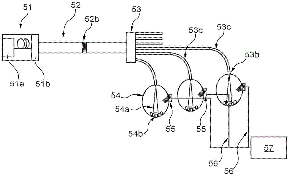
The light system shown in fig. 6 is arranged for illuminating and sensing particles 54b in the sensing chamber 54. The optical system comprises a light supply 51, an HLP 52 and an N-branch fiber bundle 53. The light supplying device 51 includes a light source 51a and a beam adjuster 51 b. The light source 51a provides light, e.g., pulsed light, to the beam conditioner where it is optionally filtered, combined, and/or expanded, and the resulting beam or beams are delivered to the HLP 52. In HLP 52, the light is scrambled by multiple reflections off the sides of the HLP to have a more uniform modal power distribution at the exit end 52b of the HLP 52, and the uniform beam is delivered to the common package input end of the fiber bundle 53. The light beams provided to the common package input end of the fiber bundle 53 are uniformly distributed among the fibers of the fiber bundle 53 and guided along the N sub-fiber bundles 53c to the N exit ends 53 b. The N outlet ends 53B are arranged to provide light at the sensing chambers 54 in a spatially discrete arrangement to project the illumination beams 54a towards the particles 54B to sense one or more characteristics of the particles, such as color, content, structure, etc.
A light sensor, such as a camera 55, is disposed in each sensing chamber 54 to image light reflected from the particle 54b, and image data from the respective light sensor 55 is transmitted to a data analyzer 57 through a wire 56. The light system may for example be arranged for providing illumination for hyperspectral sensing as described in the doctor's paper "Broadband optical characterization of material properties" of Otto Abildgaard. DTU computer PHD-2014; no. 334). DOI 10.11581/DTU 00000009.
In one embodiment, the sensing chamber 54 is a pill coaters (pill coaters) and the detector system is arranged to detect whether the coating meets one or more quality parameters.
In fig. 7, the light system is configured to provide light at spatially discrete locations for illumination, e.g., for vehicle lights. The optical system comprises a light supply 61, a HLP62 and an N-branch fiber bundle 63. The light supply 61 includes a light source 61a and an optical fiber 61b that projects a light beam L4 toward the input end of the HLP62 such that the light beam L4 expands to a beam size no greater than the entrance aperture of the HLP 62. In HLP62, the light is scrambled by multiple reflections off the sides of the HLP to have a more uniform modal power distribution at the exit end of HLP62, and a more uniform beam is delivered to the common package input end of fiber bundle 63. The light beams provided to the common package input end of the HLP 63 are uniformly distributed among the fibers of the fiber bundle 63 and guided along the N sub-fiber bundles 63c to the N exit ends. The N outlet ends 53b are arranged to provide light at spatially discrete lamps 64a, 64b, 64c, which spatially discrete lamps 64a, 64b, 64c may for example comprise a left front lamp, a right front lamp, a left rear lamp, etc.
Claims (19)
1. An optical system comprising a light supply, a homogenizing light pipe having an input end and an output end, and an optical fiber bundle, the light supply comprising a laser light source and a beam adjuster for adjusting the light beam and being arranged to provide light to be received by the input end of the homogenizing light pipe, the homogenizing light pipe being configured for scrambling the received light such that the light beam at the output end of the homogenizing light pipe has uniformity in cross-sectional direction and for delivering the light beam to a common package input end of the optical fiber bundle;
wherein the beam adjuster is arranged to convey the light to the input end of the homogenizing light pipe such that the light at the input end of the homogenizing light pipe has a beam diameter that is 20% of the entrance aperture of the homogenizing light pipe; and
wherein the light delivery device is arranged relative to the input end of the homogenizing light pipe such that light from the light delivery device diverges through the beam adjuster to increase the beam diameter such that the homogenizing light pipe is filled at a distance of at most 1 centimeter from the entrance aperture of the homogenizing light pipe into the homogenizing light pipe.
2. The light system of claim 1 wherein the light at the input end of the homogenizing light pipe has a beam diameter that is at least 90% of the entrance aperture of the homogenizing light pipe.
3. The optical system of claim 1, wherein the fiber bundle is an N-branch fiber bundle comprising N output sub-fiber bundles, each output sub-fiber bundle comprising at least two optical fibers, and wherein the optical fibers of the fiber bundle are arranged such that each of the N output sub-fiber bundles comprises randomly selected optical fibers relative to their position at a common package input end of the optical fibers.
4. The light system of claim 1, wherein the laser light source is selected from a fiber laser, a solid state laser, a semiconductor laser, or any combination thereof.
5. The light system of claim 4, wherein the light providing means comprises two or more lasers.
6. The light system of claim 1, wherein the laser light source spans at least 100 nm.
7. The optical system according to claim 1, wherein the light provision device comprises a wavelength filter, which is wavelength tunable and configured to filter out two or more wavelength intervals from the input light beam, and/or the light provision device comprises at least two wavelength filters for filtering out two or more wavelength intervals from the input light beam.
8. The light system according to claim 1, wherein the light supplying means comprises a wavelength combiner configured to combine light from one or more wavelength filters and/or unfiltered light from one or more of the laser light sources.
9. The light system of claim 1, wherein the light supply is configured to provide the light to the input of the homogenizing light pipe directly from the laser light source, directly from a wavelength filter, or directly from a wavelength combiner.
10. The light system according to claim 1, wherein the light supplying means comprises an output optical fiber arranged for supplying the light to the input end of the homogenizing light pipe, the output optical fiber having a numerical aperture of at least 0.10.
11. The light system as claimed in claim 1, wherein the light supplying means is arranged relative to the input end of the homogenizing light pipe such that the light beam from the light supplying means diverges to have a beam diameter at the input end of the homogenizing light pipe that is at least 50% of the entrance aperture of the homogenizing light pipe.
12. The light system of claim 1, wherein the homogenizing light pipe is configured to scramble the light from the light providing means such that the light beam at the output end of the homogenizing light pipe has a uniform modal power distribution.
13. The light system of claim 1, wherein the laser light source is configured for generating a light beam having a first beam M2Factor of the first light beam M, and the homogenizing light pipe is configured to scramble the light beam to convert the first light beam M into the second light beam M2Factor-added to the second beam M2Factor greater than the first beam M2A factor.
14. The light system of claim 13, wherein the second beam of light M2The factor is at least 10% greater.
15. The light system of claim 1, wherein the bundle of optical fibers has a core fill factor of at least 0.5 at its common input end.
16. The light system of claim 6, wherein the laser light source is a supercontinuum light source.
17. The light system as claimed in claim 11, wherein the light supplying means is arranged relative to the input end of the homogenizing light pipe such that the light beam from the light supplying means diverges to have a beam diameter at the input end of the homogenizing light pipe that is at least 75% of the entrance aperture of the homogenizing light pipe.
18. The light system of claim 1, wherein at least 50% of the optical power of the diverging beam has a ray angle that is lower than the acceptance angle of the homogenizing light pipe.
19. The optical system of claim 18, wherein at least 50% of the optical power of the diverging beam has a ray angle that achieves an acceptance angle of a majority of the number of optical fibers of the optical fiber bundle.
Applications Claiming Priority (3)
| Application Number | Priority Date | Filing Date | Title |
|---|---|---|---|
| DKPA201770308 | 2017-05-04 | ||
| DKPA201770308 | 2017-05-04 | ||
| PCT/DK2018/050091 WO2018202270A1 (en) | 2017-05-04 | 2018-05-02 | Light system for supplying light |
Publications (2)
| Publication Number | Publication Date |
|---|---|
| CN110692003A CN110692003A (en) | 2020-01-14 |
| CN110692003B true CN110692003B (en) | 2022-02-18 |
Family
ID=64016869
Family Applications (1)
| Application Number | Title | Priority Date | Filing Date |
|---|---|---|---|
| CN201880036464.4A Active CN110692003B (en) | 2017-05-04 | 2018-05-02 | Light system for providing light |
Country Status (4)
| Country | Link |
|---|---|
| US (2) | US11474288B2 (en) |
| EP (1) | EP3619564B1 (en) |
| CN (1) | CN110692003B (en) |
| WO (1) | WO2018202270A1 (en) |
Families Citing this family (4)
| Publication number | Priority date | Publication date | Assignee | Title |
|---|---|---|---|---|
| US11156846B2 (en) * | 2019-04-19 | 2021-10-26 | Kla Corporation | High-brightness illumination source for optical metrology |
| WO2022149358A1 (en) * | 2021-01-06 | 2022-07-14 | 株式会社島津製作所 | Laser device, underwater optical wireless communication device, and laser machining device |
| CN113983425B (en) * | 2021-10-28 | 2023-11-24 | 重庆睿博光电股份有限公司 | Light guide structure capable of being uniformly lighted, slender light guide and atmosphere lamp mounting structure |
| US20250261845A1 (en) * | 2024-02-21 | 2025-08-21 | Alcon Inc. | Utilizing fiber bundles and homogenizers for uniform illumination of ophthalmology surgical microscopes |
Citations (5)
| Publication number | Priority date | Publication date | Assignee | Title |
|---|---|---|---|---|
| US5838865A (en) * | 1997-06-05 | 1998-11-17 | Clarity Visual Systems, Inc. | Fiber optic light homogenizer for use in projection displays |
| WO2001046734A1 (en) * | 1999-12-20 | 2001-06-28 | Cogent Light Technologies, Inc. | Coupling of high intensity light into low melting point optical fibers |
| CN1515923A (en) * | 2003-01-02 | 2004-07-28 | 财团法人工业技术研究院 | Light Homogenization Microscopic Imaging Device |
| US6862091B2 (en) * | 2001-04-11 | 2005-03-01 | Inlight Solutions, Inc. | Illumination device and method for spectroscopic analysis |
| CN104048214A (en) * | 2013-03-14 | 2014-09-17 | 株式会社理光 | Light source unit, lighting apparatus and image projection apparatus |
Family Cites Families (37)
| Publication number | Priority date | Publication date | Assignee | Title |
|---|---|---|---|---|
| US4297000A (en) * | 1979-01-11 | 1981-10-27 | Fries James E | Solar lighting system |
| US4553238A (en) * | 1983-09-30 | 1985-11-12 | The Board Of Trustees Of The Leland Stanford University | Fiber optic amplifier |
| GB2222923B (en) * | 1988-09-14 | 1992-09-23 | Marconi Gec Ltd | Display apparatus |
| US5936719A (en) | 1996-07-16 | 1999-08-10 | Johnson; Robert W. | Test unit and method for simultaneous testing of multiple optical fibers |
| DE29624210U1 (en) * | 1996-12-10 | 2001-05-23 | Spectral Diagnostic Ltd., Migdal Haemek | Device for the simultaneous detection of multiple fluorophores in in situ hybridization and chromosome staining |
| EP0886174A3 (en) * | 1997-06-18 | 2001-03-07 | Nippon Telegraph And Telephone Corporation | White optical pulse source and applications |
| US6125228A (en) | 1998-03-04 | 2000-09-26 | Swales Aerospace, Inc. | Apparatus for beam splitting, combining wavelength division multiplexing and demultiplexing |
| US6741788B2 (en) * | 1999-07-01 | 2004-05-25 | Honeywell International Inc | Efficient light distribution system |
| GB2354899A (en) * | 1999-10-02 | 2001-04-04 | Sharp Kk | Optical device for projection display |
| CA2386952A1 (en) | 2002-05-17 | 2003-11-17 | Exfo Photonic Solutions Inc. | Radiation power demultiplexer |
| US7318644B2 (en) * | 2003-06-10 | 2008-01-15 | Abu-Ageel Nayef M | Compact projection system including a light guide array |
| US7684668B2 (en) * | 2003-12-23 | 2010-03-23 | The Boeing Company | Directional light homogenizer assembly |
| US7848605B2 (en) * | 2004-05-24 | 2010-12-07 | Trutouch Technologies, Inc. | Method of making optical probes for non-invasive analyte measurements |
| US7155106B2 (en) * | 2004-05-28 | 2006-12-26 | The Boeing Company | High efficiency multi-spectral optical splitter |
| WO2007038495A2 (en) | 2005-09-26 | 2007-04-05 | Edmund Optics, Inc. | Light integrator with circular light output |
| US8443524B2 (en) * | 2007-02-01 | 2013-05-21 | Michael Rogler Kildevaeld | Multi-purpose utility level |
| DE102007057868B4 (en) * | 2007-11-29 | 2020-02-20 | LIMO GmbH | Device for generating a linear intensity distribution |
| JP5227038B2 (en) * | 2008-01-16 | 2013-07-03 | 三菱電線工業株式会社 | Optical fiber |
| CN101477242A (en) * | 2008-05-15 | 2009-07-08 | 郑维彦 | Uniform high-efficiency lighting system used in night viewing system |
| JP2010025558A (en) * | 2008-07-15 | 2010-02-04 | Topcon Corp | Optical system for measurement |
| BR112012023287A2 (en) * | 2010-03-17 | 2017-03-21 | Zeng Haishan | apparatus and method for multispectral imaging, and method for quantifying physiological and morphological information of tissue |
| WO2012040581A1 (en) * | 2010-09-24 | 2012-03-29 | Illumitex, Inc. | High na optical system and device |
| US20130162952A1 (en) * | 2010-12-07 | 2013-06-27 | Laser Light Engines, Inc. | Multiple Laser Projection System |
| CN102540736B (en) * | 2010-12-10 | 2014-11-12 | 上海微电子装备有限公司 | Uniformity compensation device applied to large field-of-view montage illumination |
| US8573823B2 (en) * | 2011-08-08 | 2013-11-05 | Quarkstar Llc | Solid-state luminaire |
| JP5879285B2 (en) * | 2012-02-29 | 2016-03-08 | 富士フイルム株式会社 | Acoustic wave detection probe and photoacoustic measurement device |
| EP2992384B1 (en) * | 2012-06-01 | 2019-07-24 | NKT Photonics A/S | A supercontinuum light source, a system and a method of measuring |
| US8845163B2 (en) * | 2012-08-17 | 2014-09-30 | Ultratech, Inc. | LED-based photolithographic illuminator with high collection efficiency |
| CN103268016B (en) | 2013-05-31 | 2016-05-04 | 西安炬光科技有限公司 | A kind of fiber coupled laser diode homogenizing method and device |
| CN105793766A (en) * | 2013-12-20 | 2016-07-20 | 华为技术有限公司 | Light source apparatus and method for generating a mixed-color light beam |
| US10408402B2 (en) * | 2014-03-10 | 2019-09-10 | Robe Lighting S.R.O. | Optical system for a LED luminaire |
| CN104201545B (en) * | 2014-08-06 | 2016-06-15 | 深圳大学 | Based on the ultra broadband super continuum source of two waveband optical fiber laser |
| EP3234455B1 (en) | 2014-12-16 | 2023-08-23 | Cellomics, Inc | Optic homogenizer |
| US10261330B2 (en) * | 2015-08-25 | 2019-04-16 | Christie Digital Systems Usa, Inc. | System for producing an output light beam of a given spectrum |
| DK178899B1 (en) * | 2015-10-09 | 2017-05-08 | 3Dintegrated Aps | A depiction system |
| WO2017127713A1 (en) * | 2016-01-20 | 2017-07-27 | Telebrands Corp. | Illuminating apparatus |
| US10018560B2 (en) * | 2016-02-02 | 2018-07-10 | Kla-Tencor Corporation | System and method for hyperspectral imaging metrology |
-
2018
- 2018-05-02 EP EP18795074.6A patent/EP3619564B1/en active Active
- 2018-05-02 CN CN201880036464.4A patent/CN110692003B/en active Active
- 2018-05-02 US US16/610,195 patent/US11474288B2/en active Active
- 2018-05-02 WO PCT/DK2018/050091 patent/WO2018202270A1/en not_active Ceased
-
2022
- 2022-07-15 US US17/865,761 patent/US20220350070A1/en active Pending
Patent Citations (5)
| Publication number | Priority date | Publication date | Assignee | Title |
|---|---|---|---|---|
| US5838865A (en) * | 1997-06-05 | 1998-11-17 | Clarity Visual Systems, Inc. | Fiber optic light homogenizer for use in projection displays |
| WO2001046734A1 (en) * | 1999-12-20 | 2001-06-28 | Cogent Light Technologies, Inc. | Coupling of high intensity light into low melting point optical fibers |
| US6862091B2 (en) * | 2001-04-11 | 2005-03-01 | Inlight Solutions, Inc. | Illumination device and method for spectroscopic analysis |
| CN1515923A (en) * | 2003-01-02 | 2004-07-28 | 财团法人工业技术研究院 | Light Homogenization Microscopic Imaging Device |
| CN104048214A (en) * | 2013-03-14 | 2014-09-17 | 株式会社理光 | Light source unit, lighting apparatus and image projection apparatus |
Also Published As
| Publication number | Publication date |
|---|---|
| EP3619564A1 (en) | 2020-03-11 |
| WO2018202270A1 (en) | 2018-11-08 |
| US11474288B2 (en) | 2022-10-18 |
| EP3619564A4 (en) | 2021-01-20 |
| CN110692003A (en) | 2020-01-14 |
| US20200116913A1 (en) | 2020-04-16 |
| US20220350070A1 (en) | 2022-11-03 |
| EP3619564B1 (en) | 2025-07-16 |
Similar Documents
| Publication | Publication Date | Title |
|---|---|---|
| US20220350070A1 (en) | Light system for supplying light | |
| US11703635B2 (en) | Delivery fiber assembly and a broad band source | |
| JPH10311905A (en) | Refractive index distribution type lens optical device | |
| AU2004229991A1 (en) | Light distribution system | |
| US9331782B2 (en) | Optical transmission system | |
| CN109946793A (en) | A wavelength division multiplexer and a stimulated emission loss beam multiplexer | |
| US9001850B2 (en) | Excitation unit for a fiber laser | |
| JP6535848B2 (en) | Chip-type bundle fiber multiplexer and chip-type multi-wavelength light source | |
| US11454763B2 (en) | Light source assembly | |
| CN101299076B (en) | Optical fibre bundle and light source apparatus | |
| WO2014077069A1 (en) | Optical multiplexer device | |
| CN113848652A (en) | Shunt light equalizing system, laser device and gene sequencing system | |
| JP2002534788A (en) | Method and apparatus for coupling a light source to a light guide | |
| US6707964B2 (en) | Radiation power demultiplexer | |
| JP2011221191A (en) | Beam uniformizing device and optical processing device | |
| WO2022049986A1 (en) | Pulse spectroscopy device and multi-fiber radiation unit | |
| JP2004525363A (en) | Monochromator device | |
| WO2007138262A1 (en) | Scanning confocal microscope | |
| US20150212269A1 (en) | Optical multiplexing device | |
| Noordegraaf et al. | Efficient multi-mode to single-mode conversion in a 61 port photonic lantern |
Legal Events
| Date | Code | Title | Description |
|---|---|---|---|
| PB01 | Publication | ||
| PB01 | Publication | ||
| SE01 | Entry into force of request for substantive examination | ||
| SE01 | Entry into force of request for substantive examination | ||
| GR01 | Patent grant | ||
| GR01 | Patent grant |