Disclosure of Invention
Aiming at the problems, the invention aims to provide a water-drive thickened oil numerical simulation method which is reasonable in description, strong in reliability and simple in operation and takes variable starting pressure gradient into consideration, and can provide theoretical support for researching the change rule of a thickened oil seepage field, accurately predicting the distribution of residual oil, formulating an oil field development scheme and guiding the evaluation of the potential of oil field excavation.
In order to achieve the purpose, the invention adopts the following technical scheme that the water flooding thickened oil numerical simulation method considering variable starting pressure gradient is characterized by comprising the following steps of:
s1, determining oil reservoir physical property parameters of the water-drive heavy oil block to form a simulation model of the water-drive heavy oil block;
s2, establishing a water-drive thickened oil variable starting pressure gradient numerical simulation model;
1) obtaining a relation model of oil phase starting pressure gradient and fluidity;
2) substituting the relational expression of the oil phase starting pressure gradient and fluidity in the step 1) into the seepage motion equation of the water-drive thickened oil block, and establishing a seepage mathematical model of the water-drive thickened oil block by combining a continuous equation and a state equation;
wherein the oil phase motion equation in the seepage motion equation is
Wherein K is the permeability tensor; k
roIs the relative permeability of the oil phase, mu
oIs the viscosity of the oil phase; phi
oIs the flow potential of the oil phase; g is a starting pressure gradient;
a Hamilton operator;
3) carrying out finite difference discretization on the seepage mathematical model of the water-drive thick oil block in the step 2), and finally obtaining a variable starting pressure gradient numerical simulation model by adopting a full implicit method;
s3, initializing pressure and saturation field;
s4, solving the pressure and saturation of the water-drive thick oil block by adopting a full implicit iteration method;
s5, checking convergence conditions and material balance;
if the convergence requirement and the material balance are met, outputting parameters such as starting pressure gradient, pressure, saturation and the like of the current time step, entering the cycle calculation of the next time step, if the conditions are not met, adjusting the iteration step length, and repeating the step S4;
s6, checking whether the simulation end time is reached, if yes, outputting a starting pressure gradient field, a pressure field and a saturation field of the water-drive thick oil block, and otherwise, repeating the steps S1-S5.
Further, in step S1, the reservoir property parameters include permeability, porosity, high pressure property of the fluid, and a phase-permeability curve.
Further, in step S2, obtaining the specific content of the relationship model of the oil phase starting pressure gradient and the fluidity includes:
obtaining oil phase fluidity and starting pressure gradient data according to a rock core displacement test of a thickened oil block, fitting the oil phase fluidity and starting pressure gradient data to obtain a relation curve graph and a fitting equation of oil phase starting pressure gradient changing along with fluidity,
the fitting equation is:
further, in step S2, 2), a seepage mathematical model of the water-drive thick oil block is established as follows:
saturation equation: so+Sw+Sg=1
Capillary force equation:
outer boundary conditions:
inner boundary conditions: the production well gives the bottom flow pressure or gives the oil production, the liquid production and the water production, and the water injection well gives the bottom flow pressure or the injection quantity;
in the above formula, q
ov,q
wv,q
gvThe unit time injection volume or the unit time extraction volume of oil, water and gas are respectively; s
o, S
w,S
gOil, water and gas saturation respectively; p
o,P
w,P
gThe pressure of oil, water and gas phases; phi
o, Φ
w,Φ
gThe flow potentials of oil, water and gas are respectively; rho
o,ρ
w,ρ
gThe densities of oil, water and gas phases are respectively; b is
o,B
w,B
gThe volume coefficients of oil, water and gas phases are respectively; mu.s
o,μ
w,μ
gThe viscosity of oil, water and gas phases; r
so,R
swThe ratio of dissolved gas to oil in oil phase and water phase respectively; k
ro,K
rw,K
rgRelative permeability of oil, water and gas phases; k is the permeability tensor; phi is the rock porosity; d is the oil reservoir depth; g is the acceleration of gravity; n is the normal direction of the oil reservoir outer boundary; the gamma is the oil reservoir outer boundary; p-
i=0Is the original formation pressure distribution under the initial condition; s
w|
i=0,S
o|
i=0Is the water-containing, oil-containing saturation distribution in the formation at initial conditions;
a Hamilton operator; g is the acceleration of gravity; f is a flow correction factor; p
cowThe capillary force between oil and water phases; p
cogThe capillary force between the gas phase and the oil phase; g is the start pressure gradient.
Further, in step S2, step 3), the process of obtaining the variable start pressure gradient numerical simulation model is as follows:
implicit difference equations of 3 components of oil, gas and water are respectively
Gas component:
wherein Q is
vo=V
bq
vo;Q
vw=V
bq
vw;Q
vg=V
bq
vg;
Φ
l=P
l-ρ
lgD, (l ═ o, w, g); n represents the nth time step; l represents the number of iterations, Δ t time step; v
bIs the grid block volume;
represents n +1 time step P
o,S
wThe difference between the (l + 1) th iteration and the (l) th iteration of the equal parameter;
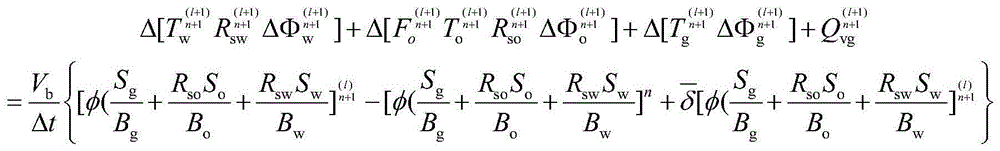
for 3 groups of oil, gas and waterExpanding a divided implicit differential equation, and neglecting delta [ (. cndot. cndot.) delta S in the calculation process of the n +1 time step and the l +1 iteration stepw]·Δ[(···)δPo],Δ[(···)δPo]·Δ[(···)δPo]And (5) equaling the second order minimums, and finishing the equation:
oil component left term:
water component left end term:
gas component left end term:
oil component right end item:
the right end of the water component:
wherein,
the right end of the gas component:
wherein,
further, in the step S4, the concrete process of solving the pressure and saturation of the water-drive thick oil block is as follows:
before solving the pressure and the saturation of the water-drive thick oil block in the next iteration step, the nonlinear coefficient calculation is carried out on the oil deposit physical property parameters calculated in the previous iteration step, and the method specifically comprises the following steps:
① calculating oil phase starting pressure gradient G of each grid block in each direction by interpolation of oil phase fluidity of each grid when starting pressure gradient is considered, calculating oil phase potential gradient on interface, and comparing the oil phase starting pressure gradient G with the oil phase potential gradient model
Finally, the flow correction factor f is calculated, if
Then
If it is
F is 0;
② if the start-up pressure gradient is not considered, f is 1;
and assembling and calculating a Jacobi matrix on the basis of nonlinear coefficient calculation, and then solving the Jacobi matrix by adopting a GPU parallel efficient algorithm to obtain pressure and saturation.
Further, the method for calculating the oil phase potential gradient on the interface comprises the following steps:
and subtracting the oil phase potentials of two adjacent grids, and dividing the subtracted value by the distance between the central points of the two grids to obtain the oil phase potential gradient.
Further, in step S5, the convergence condition is that the difference between the current time step and the previous time step is less than 0.001; the material balance test adopts an increment material balance method or an accumulation material balance method;
the incremental material balance method comprises the following calculation formula:
the formula for the cumulative material balance method is:
in the formula,
representing the volume of any grid block in the oil reservoir, wherein one oil reservoir divides a plurality of grids, i, j and k represent the space positions of the grids, and V
bIs the grid block volume; phi represents the rock porosity; alpha is alpha
cTo the volume conversion factor, alpha
c=5.614583;B
lExpressing volume coefficients, wherein l represents oil, gas and water three phases, and l is o, w and g; n represents the nth time step; m represents the cumulative time step; a Δ t time step;
the flow rate of each phase in the three directions of x, y and z is shown; n is
x、 n
y、n
zThe grid numbers in the three directions of x, y and z are respectively; i is
MB、C
MBThe variation range is 0.995-1.005.
By adopting the technical scheme, the invention has the following advantages: the invention relates to a water drive thickened oil numerical simulation method considering a starting pressure gradient, which comprises the steps of firstly establishing a starting pressure gradient variation relation model along with the fluidity, then substituting the starting pressure gradient variation relation model along with the fluidity into a seepage motion equation of a water drive thickened oil block to obtain a seepage mathematical model of the water drive thickened oil block, carrying out finite difference discretization on the seepage mathematical model of the water drive thickened oil block, finally obtaining a variable starting pressure gradient numerical simulation model by adopting a full implicit method, and calculating by utilizing the variable starting pressure gradient numerical simulation model and combining the full implicit iteration method to obtain a starting pressure gradient field, a pressure field and a saturation field of the water drive thickened oil block; starting from the flowing mechanism of the heavy oil, the method can realize the accurate representation of the water drive characteristics of the heavy oil reservoir, simultaneously ensures the stability and the reliability of the numerical simulation result of the oil reservoir by using a fully-implicit solving method, and provides theoretical support for researching the change rule of the heavy oil seepage field, accurately predicting the distribution of the residual oil, formulating an oil field development scheme and guiding the evaluation of the potential excavation potential of the oil field.
Detailed Description
The preferred embodiments of the present invention will be described in detail below with reference to the accompanying drawings so that the objects, features and advantages of the invention can be more clearly understood. It should be understood that the embodiments shown in the drawings are not intended to limit the scope of the present invention, but are merely intended to illustrate the spirit of the technical solution of the present invention.
As shown in fig. 1, the present invention provides a water-flooding thickened oil numerical simulation method considering variable start pressure gradient, which comprises the following steps:
s1, determining oil reservoir physical property parameters of the water-drive heavy oil block to form a simulation model of the water-drive heavy oil block;
the physical property parameters of the oil reservoir specifically include permeability, porosity, high-pressure physical property of fluid, a phase permeability curve and the like.
S2, establishing a water-drive thickened oil variable starting pressure gradient numerical simulation model; the specific process is as follows:
1) obtaining a relation model of oil phase starting pressure gradient and fluidity; the specific contents are as follows:
obtaining oil phase fluidity and starting pressure gradient data according to a rock core displacement test of a thickened oil block, fitting the oil phase fluidity and starting pressure gradient data to obtain a relation curve graph and a fitting relation of oil phase starting pressure gradient along with change of fluidity, namely a relation model of oil phase starting pressure gradient and fluidity,
the relationship model of the oil phase starting pressure gradient and the fluidity is as follows:
2) research shows that the simulated starting pressure gradient model is more suitable for the actual situation when the starting pressure gradient change is considered, so the oil phase motion equation in the seepage motion equation of the water-drive thickened oil block is as follows:
substituting the relational expression of the oil phase starting pressure gradient and fluidity in the step 1) into a seepage motion equation of the water-drive thickened oil block, and establishing a seepage mathematical model of the water-drive thickened oil block by combining a state equation and a continuity equation;
the seepage mathematical model is as follows:
saturation equation: so+Sw+Sg=1
Capillary force equation:
outer boundary conditions:
inner boundary conditions: the production well gives the bottom flow pressure or gives the oil production, the liquid production and the water production, and the water injection well gives the bottom flow pressure or the injection quantity;
in the above formula, q
ov,q
wv,q
gvThe unit time injection volume or the unit time extraction volume of oil, water and gas are respectively; s
o, S
w,S
gOil, water and gas saturation respectively; p
o,P
w,P
gThe pressure of oil, water and gas phases; phi
o, Φ
w,Φ
gThe flow potentials of oil, water and gas are respectively; rho
o,ρ
w,ρ
gThe densities of oil, water and gas phases are respectively; b is
o,B
w,B
gThe volume coefficients of oil, water and gas phases are respectively; mu.s
o,μ
w,μ
gThe viscosity of oil, water and gas phases; r
so,R
swThe ratio of dissolved gas to oil in oil phase and water phase respectively; k
ro,K
rw,K
rgRelative permeability of oil, water and gas phases; k is the permeability tensor; phi is the rock porosity; d is the oil reservoir depth; g is the acceleration of gravity; n is the normal direction of the oil reservoir outer boundary; the gamma is the oil reservoir outer boundary; p-
i=0Is the original formation pressure distribution under the initial condition; s
w|
i=0,S
o|
i=0Is the water-containing, oil-containing saturation distribution in the formation at initial conditions;
is Hamilton operator(ii) a g is the acceleration of gravity; f is a flow correction factor; p
cowThe capillary force between oil and water phases; p
cogThe capillary force between the gas phase and the oil phase; g is the start pressure gradient.
3) Carrying out finite difference discretization on the seepage mathematical model of the water-drive thick oil block in the step 2), and finally obtaining a variable starting pressure gradient numerical simulation model by adopting a full implicit method;
implicit difference equations of 3 components of oil, gas and water are respectively
gas component:
wherein Q is
vo=V
bq
vo;Q
vw=V
bq
vw;Q
vg=V
bq
vg;
Φ
l=P
l-ρ
lgD, (l ═ o, w, g); n represents the nth time step; l represents the number of iterations, Δ t time step; v
bIs the grid block volume;
represents n +1 time step P
o,S
wAnd (4) the difference value of the (l + 1) th iteration and the l th iteration of the equal parameter.
Expanding an implicit difference equation of 3 components of oil, gas and water, and neglecting delta [ (. cndot. cndot.) delta S in the calculation process of the n +1 time step and the l +1 iteration stepw]·Δ[(···)δPo],Δ[(···)δPo]·Δ[(···)δPo]And (5) equaling the second order minimums, and finishing the equation:
oil component left term:
water component left end term:
gas component left end term:
oil component right end item:
the right end of the water component:
the right end of the gas component:
wherein,
s3, initializing pressure and saturation field;
s4, solving the pressure and saturation of the water-drive thick oil block by adopting a full implicit iteration method;
before solving the pressure and saturation of the water-drive thick oil block in the next iteration step, the nonlinear coefficient calculation is performed on the oil reservoir physical property parameters calculated in the previous iteration step, as shown in fig. 2, the method specifically includes:
① calculating oil phase starting pressure gradient G of each grid block in each direction by interpolation of oil phase fluidity of each grid when starting pressure gradient is considered, calculating oil phase potential gradient on interface, and comparing the oil phase starting pressure gradient G with the oil phase potential gradient model
Finally, the flow correction factor f is calculated, if
Then
If it is
F is 0;
the method for calculating the oil phase potential gradient on the interface is as follows:
the flow potential of oil, water and gas is phil=Pl-ρlgD, (l ═ o, w, g); each grid has own flow potential, the oil phase potentials of two adjacent grids are subtracted, and the difference is divided by the distance between the central points of the two grids to obtain the oil phase potential gradient.
② if the start-up pressure gradient is not considered, f is 1;
assembling and calculating a Jacobi matrix on the basis of nonlinear coefficient calculation, and then solving the Jacobi matrix by adopting a GPU (GPU is a video card or a graphics processor) parallel efficient algorithm to obtain pressure and saturation;
s5, checking convergence conditions and material balance;
if the convergence requirement and the material balance are met, outputting parameters such as starting pressure gradient, pressure, saturation and the like of the current time step, entering the cycle calculation of the next time step, if the conditions are not met, adjusting the iteration step length, and repeating the step S4;
the convergence condition may be set to be approximately that the difference between the current time step and the previous time step is less than 0.001;
the material balance test is the ratio of the cumulative mass flow to the net mass flow into and out of the reservoir boundary. The material balance test carried out at a certain time step is called incremental material balance, by IMBRepresents, i.e.:
the material balance test can also be carried out over a period of time, this test method being called cumulative material balance, with CMBNamely:
in the formula,
representing the volume of any grid block in the oil reservoir, wherein one oil reservoir divides a plurality of grids, i, j and k represent the space positions of the grids, and V
bIs the grid block volume; phi represents the rock porosity; alpha is alpha
cTo the volume conversion factor, alpha
c=5.614583;B
lExpressing volume coefficients, wherein l represents oil, gas and water three phases, and l is o, w and g; n represents the nth time step; m represents the cumulative time step; a Δ t time step;
the flow rate of each phase in the three directions of x, y and z is shown; n is
x、 n
y、n
zThe grid numbers in the three directions of x, y and z are respectively; i is
MB、C
MBThe variation ranges are all between 0.995 and 1.005;
these two material balance tests can be carried out at each time step, CMBThe errors occurring at different time steps are typically averaged. To obtain an acceptable solution, the material balance test results of the two equations must be consistent.
S6, checking whether the simulation end time is reached, if yes, outputting a starting pressure gradient field, a pressure field and a saturation field of the water-drive thick oil block, and otherwise, repeating the steps S1-S5.
The invention is illustrated by the following specific example:
FIG. 3 is a schematic diagram of a model of the variation of the starting pressure gradient with fluidity according to the present invention. According to the core displacement test research of a typical thickened oil block, the bent section of a thickened oil seepage curve is not obvious and is in quick transition, and crude oil quickly enters quasi-linear seepage after the displacement pressure gradient is larger than the starting pressure gradient. A rock core displacement experiment of the thick oil zone shows that a good power relation exists between the starting pressure gradient and the fluidity, and a model parameter value can be obtained through experimental data fitting so as to determine the change relation of the starting pressure gradient along with the fluidity.
In order to verify the reasonability and accuracy of a simulator newly developed by using the method, the software is subjected to degradation test mainly from two aspects of symmetry test and ECLIPSE development index comparison test, and the method is explained in detail by matching with the attached drawings. And establishing a mechanism model of a five-point system for simulation verification, wherein the step length of a plane grid is 10m, the step length of a longitudinal grid is 5m, and the grid number is 31 multiplied by 5. The porosity of the model is 0.30, the permeability of 1-2 small layers in the plane direction is 800mD, the permeability of the vertical direction is 20mD, the permeability of 3-5 small layers in the plane direction is 50mD, and the permeability of the vertical direction is 10 mD. The four water injection wells are 20m3Constant rate of injection/d, production rate of 80m from the production well3And d, keeping the injection-production balance, wherein the simulation time is 18 years.
Fig. 4 is a symmetry test result of the novel simulator compiled by the method of the present invention, and the distribution of the saturation field (as shown in fig. 4 a) and the pressure field (as shown in fig. 4 b) output by the simulator can be found to have good symmetry by analyzing, and the shapes of the four water injection well swept areas are the same, which proves that the calculation result of the simulator is reliable and stable.
FIG. 5 is a comparative test result of development indexes of a new simulator and ECLIPSE compiled by the method of the present invention, and the results of comparing the oil production rate and the water content of the simulator and the ECLIPSE simulation show that the simulation results of the two simulators are basically consistent except for a slight difference in the oil production rate in a time period of 3000d-4000d, and the statistical error of the new simulator is 0.16% compared with the ECLIPSE software, which indicates that the calculation result of the simulator is accurate.
And (3) establishing a reverse five-point mechanism model aiming at the actual production condition of the typical heavy oil block, wherein the basic parameters of the model are consistent with the mechanism model, and a relation curve of starting pressure gradient and fluidity is increased during simulation. The simulator researched and developed by the method disclosed by the invention is used for carrying out variable starting pressure gradient model research and researching the influence of the starting pressure gradient on the development effect.
FIG. 6 is a saturation field distribution of lower permeation layers with and without regard to a variable activation pressure gradient. FIG. 7 is a pressure field distribution of a lower permeation layer with and without regard to a variable actuation pressure gradient. FIG. 8 is a saturation field distribution for a higher permeation layer with and without regard to a variable activation pressure gradient. FIG. 9 is a pressure field distribution of a higher permeation layer with and without regard to a variable activation pressure gradient. FIG. 10 is a graph comparing water cut versus production levels curves with and without consideration of a variable startup pressure gradient.
Simulation results of the saturation field showed that: the starting pressure gradient can generate an additional seepage resistance to the thick oil water drive, the formation of a channel with the minimum seepage resistance is accelerated, most injected water flows along the dominant channel, and the water drive swept area is reduced. The simulation result of the pressure field shows that: the existence of the starting pressure gradient causes the pressure contour line distribution near the water injection well to be dense and the area of a high pressure swept area to be increased, and four production wells have lower pressure and are easy to form a low pressure area compared with a linear seepage formation because the formation of the dominant channel has early water breakthrough time. The results of the saturation and pressure field simulation of the formations with different permeabilities show that: the residual oil saturation distribution of the stratum with higher permeability is obviously influenced by the starting pressure gradient, and the influence of contradiction between the layers and in the stratum is in secondary importance; the resistance of the stratum with lower permeability is relatively larger, injected water is not easy to flow in, the influence of the starting pressure gradient on the swept area of the injected water is not obvious, but the saturation of the residual oil in the swept area is relatively higher. Therefore, the difference of interlayer seepage resistance is aggravated by starting pressure gradient, and the interlayer contradiction is aggravated. From development index curves such as water content, extraction degree and the like, the extraction degree of a well group is reduced due to the starting pressure gradient of the thickened oil, the water content is increased quickly in an early stage, and the development effect is poor.
Intercepting one anti-five well group in the thickened oil block X for research, wherein the simulation time period is 1998.10.1-2017.11.1, and simulating the relation curve of the starting pressure gradient and the fluidity of the thickened oil in the block X measured by experiments by adopting the actual data of the oil field production allocation and injection allocation.
FIG. 11 is a comparison of a water cut curve fit of a variable actuation pressure gradient simulator programmed using the method of the present invention to a prior art ECLIPSE. The traditional numerical simulation method is adopted for history fitting, the difference between a fitting result and production data in the early and middle stages is large, the difference between the water breakthrough time of an oil well and the actual production is about half a year, accurate fitting in the early and middle stages is difficult to realize only by adjusting a physical property parameter model of a reservoir, and high-precision fitting needs to be realized by starting from the seepage characteristic of thickened oil. The variable-start pressure gradient simulator compiled by the method can realize high-precision fitting of the water content. Obviously, the thickened oil variable-starting pressure gradient numerical simulation physical background is rich and is more close to the field actual production, and theoretical and technical support can be provided for the reasonable development and adjustment of thickened oil water drive.
The invention relates to a water-drive thickened oil numerical simulation method considering a starting pressure gradient, which comprises the steps of establishing a model of the change relation of the starting pressure gradient along with the fluidity, interpolating the starting pressure gradient value of each grid node by the oil phase fluidity, and calculating the flow correction coefficient of each grid in each direction and updating a conductivity data field; the method starts from the flow mechanism of the heavy oil, can realize the accurate representation of the water drive characteristics of the heavy oil reservoir, ensures the stability and the reliability of the numerical simulation result of the reservoir by using a fully-implicit solving method, and provides theoretical support for researching the change rule of the heavy oil seepage field, accurately predicting the distribution of the residual oil, formulating an oil field development scheme and guiding the evaluation of the potential excavation potential of the oil field.
The present invention has been described with reference to the above embodiments, and the structure, arrangement, and connection of the respective members may be changed. On the basis of the technical scheme of the invention, the improvement or equivalent transformation of the individual components according to the principle of the invention is not excluded from the protection scope of the invention.