CN110680488A - Lateral connecting device and spinal internal fixation system using the same - Google Patents
Lateral connecting device and spinal internal fixation system using the same Download PDFInfo
- Publication number
- CN110680488A CN110680488A CN201910872701.7A CN201910872701A CN110680488A CN 110680488 A CN110680488 A CN 110680488A CN 201910872701 A CN201910872701 A CN 201910872701A CN 110680488 A CN110680488 A CN 110680488A
- Authority
- CN
- China
- Prior art keywords
- connecting rod
- transverse
- clamping block
- spherical
- ball head
- Prior art date
- Legal status (The legal status is an assumption and is not a legal conclusion. Google has not performed a legal analysis and makes no representation as to the accuracy of the status listed.)
- Pending
Links
- 230000037431 insertion Effects 0.000 claims 1
- 238000003780 insertion Methods 0.000 claims 1
- 210000003128 head Anatomy 0.000 description 25
- 210000000944 nerve tissue Anatomy 0.000 description 10
- 238000010586 diagram Methods 0.000 description 6
- 238000000034 method Methods 0.000 description 6
- 230000000638 stimulation Effects 0.000 description 5
- 238000009434 installation Methods 0.000 description 4
- 210000000988 bone and bone Anatomy 0.000 description 3
- 229910001069 Ti alloy Inorganic materials 0.000 description 2
- 230000000694 effects Effects 0.000 description 2
- 210000000653 nervous system Anatomy 0.000 description 2
- 230000008569 process Effects 0.000 description 2
- 238000004904 shortening Methods 0.000 description 2
- 238000001356 surgical procedure Methods 0.000 description 2
- 208000018084 Bone neoplasm Diseases 0.000 description 1
- 239000000956 alloy Substances 0.000 description 1
- 238000013016 damping Methods 0.000 description 1
- 230000006837 decompression Effects 0.000 description 1
- 230000007812 deficiency Effects 0.000 description 1
- 201000010099 disease Diseases 0.000 description 1
- 208000037265 diseases, disorders, signs and symptoms Diseases 0.000 description 1
- 210000001061 forehead Anatomy 0.000 description 1
- 208000014674 injury Diseases 0.000 description 1
- 230000007794 irritation Effects 0.000 description 1
- 238000012986 modification Methods 0.000 description 1
- 230000004048 modification Effects 0.000 description 1
- 210000005036 nerve Anatomy 0.000 description 1
- 208000015122 neurodegenerative disease Diseases 0.000 description 1
- 230000002035 prolonged effect Effects 0.000 description 1
- 230000009467 reduction Effects 0.000 description 1
- 206010039722 scoliosis Diseases 0.000 description 1
- 238000006748 scratching Methods 0.000 description 1
- 230000002393 scratching effect Effects 0.000 description 1
- 239000000126 substance Substances 0.000 description 1
- 230000007704 transition Effects 0.000 description 1
- 230000008733 trauma Effects 0.000 description 1
- 238000012800 visualization Methods 0.000 description 1
Images


Classifications
-
- A—HUMAN NECESSITIES
- A61—MEDICAL OR VETERINARY SCIENCE; HYGIENE
- A61B—DIAGNOSIS; SURGERY; IDENTIFICATION
- A61B17/00—Surgical instruments, devices or methods
- A61B17/56—Surgical instruments or methods for treatment of bones or joints; Devices specially adapted therefor
- A61B17/58—Surgical instruments or methods for treatment of bones or joints; Devices specially adapted therefor for osteosynthesis, e.g. bone plates, screws or setting implements
- A61B17/68—Internal fixation devices, including fasteners and spinal fixators, even if a part thereof projects from the skin
- A61B17/70—Spinal positioners or stabilisers, e.g. stabilisers comprising fluid filler in an implant
- A61B17/7001—Screws or hooks combined with longitudinal elements which do not contact vertebrae
- A61B17/7002—Longitudinal elements, e.g. rods
-
- A—HUMAN NECESSITIES
- A61—MEDICAL OR VETERINARY SCIENCE; HYGIENE
- A61B—DIAGNOSIS; SURGERY; IDENTIFICATION
- A61B17/00—Surgical instruments, devices or methods
- A61B17/56—Surgical instruments or methods for treatment of bones or joints; Devices specially adapted therefor
- A61B17/58—Surgical instruments or methods for treatment of bones or joints; Devices specially adapted therefor for osteosynthesis, e.g. bone plates, screws or setting implements
- A61B17/68—Internal fixation devices, including fasteners and spinal fixators, even if a part thereof projects from the skin
- A61B17/70—Spinal positioners or stabilisers, e.g. stabilisers comprising fluid filler in an implant
- A61B17/7049—Connectors, not bearing on the vertebrae, for linking longitudinal elements together
- A61B17/7052—Connectors, not bearing on the vertebrae, for linking longitudinal elements together of variable angle or length
-
- A—HUMAN NECESSITIES
- A61—MEDICAL OR VETERINARY SCIENCE; HYGIENE
- A61B—DIAGNOSIS; SURGERY; IDENTIFICATION
- A61B17/00—Surgical instruments, devices or methods
- A61B17/56—Surgical instruments or methods for treatment of bones or joints; Devices specially adapted therefor
- A61B17/58—Surgical instruments or methods for treatment of bones or joints; Devices specially adapted therefor for osteosynthesis, e.g. bone plates, screws or setting implements
- A61B17/68—Internal fixation devices, including fasteners and spinal fixators, even if a part thereof projects from the skin
- A61B17/70—Spinal positioners or stabilisers, e.g. stabilisers comprising fluid filler in an implant
- A61B17/7062—Devices acting on, attached to, or simulating the effect of, vertebral processes, vertebral facets or ribs ; Tools for such devices
- A61B17/7064—Devices acting on, attached to, or simulating the effect of, vertebral facets; Tools therefor
-
- A—HUMAN NECESSITIES
- A61—MEDICAL OR VETERINARY SCIENCE; HYGIENE
- A61B—DIAGNOSIS; SURGERY; IDENTIFICATION
- A61B17/00—Surgical instruments, devices or methods
- A61B17/56—Surgical instruments or methods for treatment of bones or joints; Devices specially adapted therefor
- A61B17/58—Surgical instruments or methods for treatment of bones or joints; Devices specially adapted therefor for osteosynthesis, e.g. bone plates, screws or setting implements
- A61B17/68—Internal fixation devices, including fasteners and spinal fixators, even if a part thereof projects from the skin
- A61B17/70—Spinal positioners or stabilisers, e.g. stabilisers comprising fluid filler in an implant
- A61B17/7074—Tools specially adapted for spinal fixation operations other than for bone removal or filler handling
-
- A—HUMAN NECESSITIES
- A61—MEDICAL OR VETERINARY SCIENCE; HYGIENE
- A61B—DIAGNOSIS; SURGERY; IDENTIFICATION
- A61B17/00—Surgical instruments, devices or methods
- A61B17/56—Surgical instruments or methods for treatment of bones or joints; Devices specially adapted therefor
- A61B2017/564—Methods for bone or joint treatment
Landscapes
- Health & Medical Sciences (AREA)
- Orthopedic Medicine & Surgery (AREA)
- Neurology (AREA)
- Life Sciences & Earth Sciences (AREA)
- Surgery (AREA)
- Heart & Thoracic Surgery (AREA)
- Engineering & Computer Science (AREA)
- Biomedical Technology (AREA)
- Nuclear Medicine, Radiotherapy & Molecular Imaging (AREA)
- Medical Informatics (AREA)
- Molecular Biology (AREA)
- Animal Behavior & Ethology (AREA)
- General Health & Medical Sciences (AREA)
- Public Health (AREA)
- Veterinary Medicine (AREA)
- Prostheses (AREA)
- Surgical Instruments (AREA)
Abstract
本发明属于脊柱固定系统领域,公开了一种横向连接装置和应用其的脊柱内固定系统。根据本发明实施例的横向连接装置包括:连接杆,连接杆包括第一连接杆和第二连接杆,第一连接杆与第二连接杆二者的端部球面铰接;两个夹持块,两个夹持块分别插接在第一连接杆和第二连接杆上;以及锁紧装置,锁紧装置设置成能够对第一连接杆与第二连接杆的球面铰接处进行压紧,以实现第一连接杆与第二连接杆的相对定位。本发明的横向连接装置能够具有多维度的调节,以提高其连接后的稳定性。
The invention belongs to the field of spinal fixation systems, and discloses a transverse connection device and a spinal internal fixation system using the same. The transverse connecting device according to the embodiment of the present invention includes: a connecting rod, the connecting rod includes a first connecting rod and a second connecting rod, and the ends of the first connecting rod and the second connecting rod are spherically hinged; two clamping blocks, The two clamping blocks are respectively inserted on the first connecting rod and the second connecting rod; and a locking device, the locking device is arranged to be able to press the spherical hinge of the first connecting rod and the second connecting rod, so as to The relative positioning of the first connecting rod and the second connecting rod is achieved. The transverse connection device of the present invention can be adjusted in multiple dimensions to improve the stability after connection.
Description
技术领域technical field
本发明属于脊柱固定系统领域,具体涉及一种横向连接装置和应用其的脊柱内固定系统。The invention belongs to the field of spinal fixation systems, and in particular relates to a lateral connection device and a spinal internal fixation system using the same.
背景技术Background technique
人体的脊椎骨中相互连接的中空骨节用于容纳和保护其周边的神经系统的。当脊椎因为遗传或后天的外伤、疾病(例如骨肿瘤、脊柱侧弯、退化性疾病)等产生病变,有可能压迫到椎管内的神经系统而产生疼痛。此时就必须施以手术治疗,并且需要在椎体上安装脊柱内固定系统以达到固定、脊柱复位以及神经减压的效果。The interconnected hollow condyles in the vertebrae of the human body serve to accommodate and protect the surrounding nervous system. When the spine is damaged due to hereditary or acquired trauma, disease (such as bone tumor, scoliosis, degenerative diseases), etc., it is possible to compress the nervous system in the spinal canal and cause pain. At this time, surgical treatment must be performed, and a spinal internal fixation system needs to be installed on the vertebral body to achieve the effects of fixation, spinal reduction, and nerve decompression.
现有技术中的脊柱内固定系统包括用于与脊椎骨相连的若干对纵向脊椎杆,和用于固定相邻的纵向脊椎杆以使脊柱内固定系统形成框架结构的横向连接装置。现有技术中的横向连接装置常包括一根横杆、位于该横杆的两端的连接钩以及用于将连接钩固定在横杆上的螺母,在临床手术过程中,其不足之处包括:一方面,现有技术中的横向连接装置需要先将两个连接钩分别固定在纵向脊椎杆上,再将横杆插入钩子上的孔中,然后调整好角度位置再拧紧各个螺母,这就导致其操作步骤较为繁琐,从而使得手术时间较长,容易给患者带来更大的痛苦;另一方面,现有技术中的横向连接装置中的横杆仅能够在人体的矢状面的方向进行调节,使得其在使用时的调节方式具有局限性,不能够很好的避开相邻的纵向脊椎杆之间的脊椎骨或神经组织,从而不仅容易造成对脊椎骨或神经组织的刺激,还降低了其连接后的稳定性。Spinal internal fixation systems in the prior art include pairs of longitudinal spinal rods for connecting to the vertebrae, and transverse connecting means for securing adjacent longitudinal spinal rods so that the spinal internal fixation system forms a frame structure. The transverse connecting device in the prior art often includes a transverse rod, connecting hooks at both ends of the transverse rod, and nuts for fixing the connecting hooks on the transverse rod. During clinical operations, its shortcomings include: On the one hand, the transverse connection device in the prior art needs to first fix the two connection hooks on the longitudinal spinal rods, then insert the transverse rods into the holes on the hooks, and then adjust the angular position and then tighten the nuts, which results in The operation steps are cumbersome, so that the operation time is longer, and it is easy to bring more pain to the patient; on the other hand, the transverse rod in the transverse connection device in the prior art can only be performed in the direction of the sagittal plane of the human body Adjustment makes the adjustment method in use limited, and cannot well avoid the vertebrae or nerve tissue between adjacent longitudinal vertebral rods, which not only easily causes stimulation to the vertebrae or nerve tissue, but also reduces the the stability of its connection.
针对现有技术的不足,本领域的技术人员急需寻求一种能够具有多维度调节的横向连接装置,以提高其连接后的稳定性。In view of the deficiencies of the prior art, those skilled in the art are in urgent need of seeking a transverse connection device capable of multi-dimensional adjustment, so as to improve the stability after connection.
发明内容SUMMARY OF THE INVENTION
为了能够具有多维度调节,以提高其连接后的稳定性,本发明目的在于提供一种横向连接装置。In order to have multi-dimensional adjustment to improve the stability after connection, the present invention aims to provide a transverse connection device.
根据本发明实施例的横向连接装置包括:连接杆,连接杆包括第一连接杆和第二连接杆,第一连接杆与第二连接杆二者的端部球面铰接;两个夹持块,两个夹持块分别插接在第一连接杆和第二连接杆上;以及锁紧装置,锁紧装置设置成能够对第一连接杆与第二连接杆的球面铰接处进行压紧,以实现第一连接杆与第二连接杆的相对定位。The transverse connecting device according to the embodiment of the present invention includes: a connecting rod, the connecting rod includes a first connecting rod and a second connecting rod, and the ends of the first connecting rod and the second connecting rod are spherically hinged; two clamping blocks, The two clamping blocks are respectively inserted on the first connecting rod and the second connecting rod; and a locking device, the locking device is arranged to be able to press the spherical hinge of the first connecting rod and the second connecting rod, so as to The relative positioning of the first connecting rod and the second connecting rod is achieved.
进一步地,第一连接杆包括用于插接夹持块的第一连接板和形成在第一连接板的端部的球头部,第二连接杆包括用于插接夹持块的第二连接板和形成在第二连接板的端部的与球头部形成球面配合的筒体部,锁紧装置包括用于将球头部压固在筒体部内的压紧部。Further, the first connecting rod includes a first connecting plate for inserting the clamping block and a ball head formed at an end of the first connecting plate, and the second connecting rod includes a second connecting plate for inserting the clamping block. The connecting plate and the cylindrical body part formed at the end of the second connecting plate and forming spherical matching with the ball head part, the locking device comprises a pressing part for pressing the ball head part in the cylindrical body part.
进一步地,筒体部包括筒体本体和形成在筒体本体的侧壁上的用于插入球头部的开口,以及形成在筒体本体的内侧壁上的螺纹,压紧部为与螺纹形成螺纹配合的第一螺塞。Further, the cylindrical portion includes a cylindrical body and an opening formed on the side wall of the cylindrical body for inserting the ball head, and a thread formed on the inner side wall of the cylindrical body, and the pressing portion is formed with the thread. Threaded first plug.
进一步地,开口形成在筒体本体的与第二连接板相对的一侧。Further, the opening is formed on a side of the cylinder body opposite to the second connecting plate.
进一步地,球头部的球面上形成有多个定位平面。Further, a plurality of positioning planes are formed on the spherical surface of the ball head.
进一步地,各定位平面沿球头部的垂直于第一连接杆的最大圆周面处周向排列。Further, each positioning plane is circumferentially arranged along the largest circumferential surface of the ball head which is perpendicular to the first connecting rod.
进一步地,筒体本体的内部底面形成有与球头部球面配合的第一球面,和/或第一螺塞的与球头部相抵接的一面形成有与球头部球面配合的第二球面。Further, the inner bottom surface of the cylinder body is formed with a first spherical surface that is matched with the spherical surface of the ball head, and/or the side of the first screw plug that abuts against the ball head is formed with a second spherical surface that cooperates with the spherical surface of the ball head. .
进一步地,筒体本体的外部底面的边缘形成有与筒体本体的侧面相连的光滑的曲面。Further, the edge of the outer bottom surface of the cylindrical body is formed with a smooth curved surface connected with the side surface of the cylindrical body.
进一步地,夹持块包括:夹持块本体,夹持块本体的底部形成有用于与纵向脊椎杆相连的弹性夹持部,夹持块本体的顶部形成有螺纹孔,夹持块本体的侧壁上形成有用于第一连接板和第二连接板插入的横向通孔;和第二螺塞,第二螺塞与螺纹孔形成螺纹配合以实现第一连接板和第二连接板与夹持块本体之间的固定。其中,筒体本体的外部底面与弹性夹持部同向设置。Further, the clamping block includes: a clamping block body, an elastic clamping part for connecting with the longitudinal vertebral rod is formed at the bottom of the clamping block body, a threaded hole is formed at the top of the clamping block body, and a side of the clamping block body is formed. A transverse through hole for inserting the first connecting plate and the second connecting plate is formed on the wall; and a second screw plug, and the second screw plug is threaded with the threaded hole to realize the clamping and clamping of the first connecting plate and the second connecting plate. Fixing between block bodies. Wherein, the outer bottom surface of the cylindrical body and the elastic clamping portion are arranged in the same direction.
本发明实施例还提出了一种脊柱内固定系统。该脊柱内固定系统包括多个纵向脊椎杆和用于固定相邻的纵向脊椎杆的上述横向连接装置。其中,纵向脊椎杆与横向连接装置的弹性夹持部固定连接。The embodiment of the present invention also provides a spinal internal fixation system. The spinal internal fixation system includes a plurality of longitudinal vertebral rods and the above-described transverse connecting means for securing adjacent longitudinal vertebral rods. Wherein, the longitudinal vertebral rod is fixedly connected with the elastic clamping part of the transverse connection device.
与现有技术相比,本发明实施例的横向连接装置具有以下几方面的优点:Compared with the prior art, the transverse connection device of the embodiment of the present invention has the following advantages:
1)本发明实施例的横向连接装置可避免现有技术中的横向连接装置安装操作步骤较为繁琐的问题,从而能够有效地缩短手术时间,避免对患者带来更大的痛苦;1) The lateral connection device of the embodiment of the present invention can avoid the problem that the installation operation steps of the lateral connection device in the prior art are relatively cumbersome, thereby effectively shortening the operation time and avoiding greater pain to the patient;
2)本发明实施例的横向连接装置能够在人体的矢状面、冠状面以及横切面均能够进行多维度的调节。这与现有技术相比,多维度的调节不仅能够降低横向连接装置在使用时的调节方式的局限性,还能够更好的避开相邻的纵向脊椎杆之间的脊椎骨或神经组织,从而能够避免对脊椎骨或神经组织形成刺激的同时,还能够避免脊椎骨对横向连接装置的连接杆产生应力,进而还能够有效地提高横向连接装置连接后的稳定性;2) The transverse connection device of the embodiment of the present invention can perform multi-dimensional adjustment in the sagittal plane, coronal plane and transverse plane of the human body. Compared with the prior art, the multi-dimensional adjustment can not only reduce the limitation of the adjustment method of the transverse connecting device during use, but also better avoid the vertebral bone or nerve tissue between adjacent longitudinal vertebral rods. While avoiding stimulation to the vertebrae or nerve tissue, it can also prevent the vertebrae from generating stress on the connecting rods of the transverse connection device, and further, the stability of the transverse connection device after connection can be effectively improved;
3)本发明实施例的横向连接装置可通过分别定制不同型号的第一连接杆和第二连接杆并进行适应性的搭配使用,使得本发明实施例的横向连接装置对患者的适用性更广。3) The lateral connecting device of the embodiment of the present invention can be used by customizing the first connecting rod and the second connecting rod of different models and using them adaptively, so that the applicability of the lateral connecting device of the embodiment of the present invention to the patient is wider. .
附图说明Description of drawings
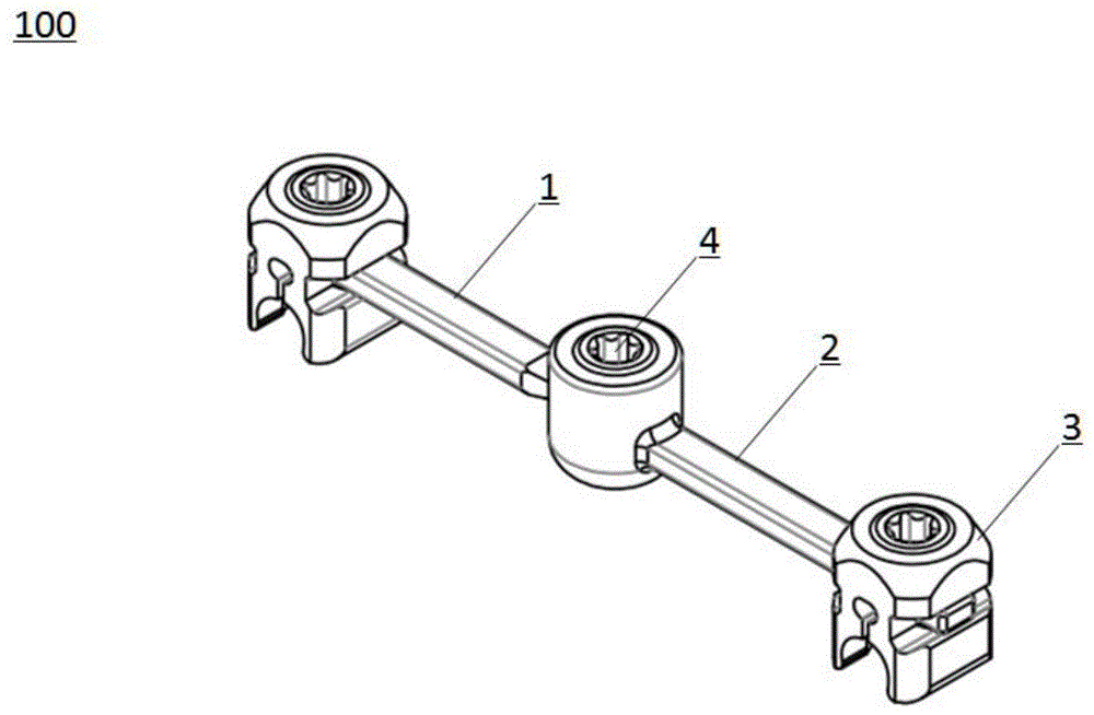
图1为本发明实施例的横向连接装置的结构示意图;1 is a schematic structural diagram of a transverse connection device according to an embodiment of the present invention;
图2为图1所示的横向连接装置的剖视图;Fig. 2 is a cross-sectional view of the transverse connecting device shown in Fig. 1;
图3为图1所示的第一连接杆的结构示意图;3 is a schematic structural diagram of the first connecting rod shown in FIG. 1;
图4为图1所示的第二连接杆的结构示意图;4 is a schematic structural diagram of the second connecting rod shown in FIG. 1;
图5为图1所示的第一螺塞的结构示意图;5 is a schematic structural diagram of the first screw plug shown in FIG. 1;
图6为图1所示的夹持块的结构示意图;FIG. 6 is a schematic structural diagram of the clamping block shown in FIG. 1;
图7为图1所示的第二螺塞的结构示意图。FIG. 7 is a schematic structural diagram of the second screw plug shown in FIG. 1 .
具体实施方式Detailed ways
为了更好的了解本发明的目的、结构及功能,下面结合附图,对本发明的一种横向连接装置做进一步详细的描述。In order to better understand the purpose, structure and function of the present invention, a transverse connection device of the present invention will be described in further detail below with reference to the accompanying drawings.
图1和图2示出了根据本发明实施例的横向连接装置100的结构。如图1和图2所示,该横向连接装置100包括:连接杆,连接杆包括第一连接杆1和第二连接杆2,第一连接杆1与第二连接杆2二者的端部球面铰接;两个夹持块3,两个夹持块3分别插接在第一连接杆1和第二连接杆2上;以及锁紧装置4,锁紧装置4设置成能够对第一连接杆1与第二连接杆2的球面铰接处进行压紧,以实现第一连接杆1与第二连接杆2的相对定位。1 and 2 illustrate the structure of a
本发明实施例的横向连接装置100在使用时,首先,可先将夹持块3分别插接在第一连接杆1和第二连接杆2上,即一个夹持块3与第一连接杆1为一部分,另一个夹持块3与第二连接杆2为一部分。再将该两部分分别与纵向脊椎杆相连,并通过第一连接杆1与第二连接杆2二者的端部形成的球面铰接直接将两部分进行相连,并适当调整角度后使用锁紧装置4对第一连接杆1与第二连接杆2的球面铰接处进行压紧以实现第一连接杆1与第二连接杆2的相对定位,从而完成了本发明实施例的安装使用。When the transverse connecting
与现有技术相比,本发明实施例的横向连接装置100具有以下几方面的优点:Compared with the prior art, the
1)本发明实施例的横向连接装置100可首先将连接杆与夹持块3进行连接后再与纵向脊椎杆固定连接,这就避免了现有技术中的横向连接装置安装操作步骤较为繁琐的问题。因此,本发明实施例的横向连接装置100能够简化安装操作步骤,从而能够有效地缩短手术时间,避免对患者带来更大的痛苦;1) The
2)本发明实施例的横向连接装置100通过第一连接杆1与第二连接杆2二者的端部形成的球面铰接的配合方式,使得本发明实施例的横向连接装置100能够在人体的矢状面、冠状面以及横切面均能够进行多维度的调节。这与现有技术相比,多维度的调节不仅能够降低横向连接装置100在使用时的调节方式的局限性,还能够更好的避开相邻的纵向脊椎杆之间的脊椎骨或神经组织,从而能够避免对脊椎骨或神经组织形成刺激,同时,还能够避免脊椎骨对横向连接装置100的连接杆产生应力,进而还能够有效地提高横向连接装置100连接后的稳定性;2) The lateral connecting
3)本发明实施例的横向连接装置100将连接杆分为第一连接杆1和第二连接杆2,还可通过分别定制化不同型号的第一连接杆1和第二连接杆2并进行适应性的搭配使用,使得本发明实施例的横向连接装置100对患者的适用性更广。3) The
在如图1和图2所示的优选地实施例中,结合图3和图4所示,第一连接杆1可包括用于插接夹持块3的第一连接板11和形成在第一连接板11的端部的球头部12,第二连接杆2可包括用于插接夹持块3的第二连接板21和形成在第二连接板21的端部的与球头部12形成球面配合的筒体部22,锁紧装置4包括用于将球头部12压固在筒体部22内的压紧部41。通过该设置,球头部12与筒体部22形成的球面配合,可使得第一连接板11能够相对于第二连接板21实现转动和摆动,从而使得本发明实施例的横向连接装置100在与纵向脊椎杆固定后可通过球面配合即可实现沿人体的矢状面、冠状面以及横切面的多维度的调节,进而使得本发明实施例的横向连接装置100的调节操作更为简单。In the preferred embodiment shown in FIG. 1 and FIG. 2 , in conjunction with FIG. 3 and FIG. 4 , the first connecting
在如图4所示的优选地实施例中,筒体部22可包括筒体本体221和形成在筒体本体221的侧壁上的用于插入球头部12的开口222,以及形成在筒体本体221的内侧壁上的螺纹(图中未示出),压紧部41为与螺纹形成螺纹配合的第一螺塞411(结合图5所示)。第一连接杆1通过球头部12插入至筒体本体221的开口222内后可实现与第二连接杆2的连接,并在适应性的调整第一连接杆1与第二连接杆2的相对的角度后,可通过第一螺塞411与筒体本体221形成的螺纹配合逐步的将第一连接杆1与第二连接杆2进行紧固。通过该设置,可在调整第一连接杆1与第二连接杆2的相对位置时,将第一螺塞411进行预压紧,这样,调整二者的相对角度时可形成有一定的阻力,从而可有效地提高调整过程的稳定性,避免造成调整的精度较差或因多次调整而导致的手术时间的延长的问题发生。In a preferred embodiment as shown in FIG. 4 , the
在一个优选地实施方式中,开口222可形成在筒体本体221的与第二连接板21相对的一侧。这样,可延长第一连接杆1与第二连接杆2在使用时的有效距离,以对横向连接装置100更为充分的利用。In a preferred embodiment, the
在如图3所示的优选地实施方式中,第一连接杆1还可包括位于第一连接板11与球头部12之间的连接第一连接板11的端部与球头部12的轴段13,轴段13的直径可小于开口222的口径,以进一步的提高第一连接杆1可相对于第二连接杆2摆动的角度。In the preferred embodiment as shown in FIG. 3 , the first connecting
在如图4所示的优选地实施例中,球头部12的球面上可形成有多个定位平面121。通过该设置,定位平面121与第一螺塞411进行压紧固定时,平面可提供与第一螺塞411更大的接触面积,从而使得二者的固定更为稳定可靠,以避免横向连接装置100与纵向脊椎杆连接后,由于人体的活动而导致的横向连接装置100的松动的问题。另外,定位平面121还可实现第一连接杆1与第二连接杆2之间的角度的微调,即在调整时,可将第一螺塞411进行预压紧,以使得在调整过程中,通过一个定位平面121过渡至另一个定位平面121可形成一定的阻尼感,以使得操作人员能够更为精确的控制调整位置。In the preferred embodiment shown in FIG. 4 , a plurality of
优选地,如图4所示,各定位平面121可沿球头部12的垂直于第一连接杆1的最大圆周面处周向排列。通过该设置,一方面,可保证第一连接杆1在相对于第二连接杆2转动时的微调和定位的稳定性;另一方面,在实际使用时,由于第一连接杆1相对于第二连接杆2的摆动角度较小,因此,该设置在能够满足第一连接杆1在相对于第二连接杆2的定位的同时,还能够降低球头部12的加工难度。Preferably, as shown in FIG. 4 , each
当然,球头部12的球面上也可全部形成有定位平面121,以进一步提高横向连接装置100的多个维度调整后的固定稳定性。另外,定位平面121的大小可也根据调整角度的需求来具体设置,以更快速的达到与人体的脊椎骨相匹配的角度,这里不做具体限定。Of course, the spherical surface of the
在如图2所示的优选地实施例中,筒体本体221的内部底面可形成有与球头部12球面配合的第一球面223,和/或第一螺塞411的与球头部12相抵接的一面形成有与球头部12球面配合的第二球面412(结合图5所示)。优选地,筒体本体221的内部底面与第一螺塞411的与球头部12相抵接的一面均形成有球面,以使球头部12能够与第一球面223和第二球面412组成的球面形成更稳定的球面配合。In the preferred embodiment shown in FIG. 2 , the inner bottom surface of the
在一个优选地实施方式中,筒体本体221的外部底面224的边缘可形成有与筒体本体221的侧面相连的光滑的曲面225(结合图2所示)。优选地,筒体本体221的外部底面224均构造为光滑的表面。通过该设置,一方面,筒体本体221的外部底面224的边缘形成光滑的曲面225可有效地避免与相邻的纵向脊椎杆之间的脊椎骨产生刮碰的问题;另一方面,外部底面224均构造为光滑的表面还可有效地防止对相邻的纵向脊椎杆之间的神经组织造成刺激。因此,本发明实施例的筒体本体221能够有效地提高患者的舒适度。In a preferred embodiment, the edge of the outer
在如图6所示的优选地实施例中,夹持块3可包括:夹持块本体31,夹持块本体31的底部形成有用于与纵向脊椎杆相连的弹性夹持部32,夹持块本体31的顶部形成有螺纹孔33,夹持块本体31的侧壁上形成有用于第一连接板1和第二连接板2插入的横向通孔34;和第二螺塞35(如图7所示),第二螺塞35与螺纹孔33形成螺纹配合以实现第一连接板1和第二连接板2与夹持块本体31之间的固定。其中,筒体本体221的外部底面224与弹性夹持部32可同向设置。通过该设置,可使得本发明实施例的横向连接装置100在通过夹持块3与纵向脊椎杆相连后,筒体本体221的外部底面224形成的光滑的表面可朝向人体的脊椎骨和神经组织的方向设置,从而有效地避免本发明实施例的横向连接装置100对相邻的纵向脊椎杆之间的脊椎骨和神经组织的刺激。In the preferred embodiment shown in FIG. 6 , the
优选地,本发明实施例的横向连接装置100可由钛合金加工而成,由于钛合金材料有很好的生物相容性和各种理化性能,因此本发明实施例的横向连接装置100可具有更好的显影效果,从而可更便于其在手术时灵活的操作性和便捷性。Preferably, the
本发明实施例还提出了一种脊柱内固定系统。该脊柱内固定系统包括多个纵向脊椎杆(图中未示出)和用于固定相邻的纵向脊椎杆的上述横向连接装置100。其中,纵向脊椎杆与横向连接装置100的弹性夹持部32固定连接。通过上文可知,本发明实施例的脊柱内固定系统使用的横向连接装置100可具有更多维度的角度的调节,从而使得脊柱内固定系统由纵向脊椎杆和横向连接装置100构成的框架结构能够更好的与人体的脊椎骨进行适配,以避免对人体的脊椎骨和神经组织造成刺激,还能够提高脊柱内固定系统的固定额稳定性。The embodiment of the present invention also provides a spinal internal fixation system. The spinal internal fixation system includes a plurality of longitudinal vertebral rods (not shown in the figures) and the above-described transverse connecting
需要注意的是,除非另有说明,本申请使用的技术术语或者科学术语应当为本发明所属领域技术人员所理解的通常意义。It should be noted that, unless otherwise specified, the technical or scientific terms used in this application should have the usual meanings understood by those skilled in the art to which the present invention belongs.
在本申请的描述中,需要理解的是,术语“顶”、“底”“内”、“外”、“周向”等指示的方位或位置关系为基于附图所示的方位或位置关系,仅是为了便于描述本发明和简化描述,而不是指示或暗示所指的装置或元件必须具有特定的方位、以特定的方位构造和操作,因此不能理解为对本发明的限制。In the description of the present application, it should be understood that the orientations or positional relationships indicated by the terms "top", "bottom", "inner", "outer", "circumferential", etc. are based on the orientations or positional relationships shown in the accompanying drawings , is only for the convenience of describing the present invention and simplifying the description, rather than indicating or implying that the indicated device or element must have a specific orientation, be constructed and operated in a specific orientation, and therefore should not be construed as a limitation of the present invention.
此外,术语“第一”、“第二”等仅用于描述目的,而不能理解为指示或暗示相对重要性或者隐含指明所指示的技术特征的数量。在本发明的描述中,“多个”的含义是两个以上,除非另有明确具体的限定。In addition, the terms "first", "second", etc. are used for descriptive purposes only, and should not be construed as indicating or implying relative importance or implying the number of indicated technical features. In the description of the present invention, "plurality" means two or more, unless otherwise expressly and specifically defined.
最后应说明的是:以上各实施例仅用以说明本发明的技术方案,而非对其限制;尽管参照前述各实施例对本发明进行了详细的说明,本领域的普通技术人员应当理解:其依然可以对前述各实施例所记载的技术方案进行修改,或者对其中部分或者全部技术特征进行等同替换;而这些修改或者替换,并不使相应技术方案的本质脱离本发明各实施例技术方案的范围,其均应涵盖在本发明的权利要求和说明书的范围当中。尤其是,只要不存在结构冲突,各个实施例中所提到的各项技术特征均可以任意方式组合起来。本发明并不局限于文中公开的特定实施例,而是包括落入权利要求的范围内的所有技术方案。Finally, it should be noted that the above embodiments are only used to illustrate the technical solutions of the present invention, but not to limit them; although the present invention has been described in detail with reference to the foregoing embodiments, those of ordinary skill in the art should understand that: The technical solutions described in the foregoing embodiments can still be modified, or some or all of the technical features thereof can be equivalently replaced; and these modifications or replacements do not make the essence of the corresponding technical solutions deviate from the technical solutions of the embodiments of the present invention. The scope of the invention should be included in the scope of the claims and description of the present invention. In particular, as long as there is no structural conflict, each technical feature mentioned in each embodiment can be combined in any manner. The present invention is not limited to the specific embodiments disclosed herein, but includes all technical solutions falling within the scope of the claims.
Claims (10)
Priority Applications (1)
| Application Number | Priority Date | Filing Date | Title |
|---|---|---|---|
| CN201910872701.7A CN110680488A (en) | 2019-09-16 | 2019-09-16 | Lateral connecting device and spinal internal fixation system using the same |
Applications Claiming Priority (1)
| Application Number | Priority Date | Filing Date | Title |
|---|---|---|---|
| CN201910872701.7A CN110680488A (en) | 2019-09-16 | 2019-09-16 | Lateral connecting device and spinal internal fixation system using the same |
Publications (1)
| Publication Number | Publication Date |
|---|---|
| CN110680488A true CN110680488A (en) | 2020-01-14 |
Family
ID=69109267
Family Applications (1)
| Application Number | Title | Priority Date | Filing Date |
|---|---|---|---|
| CN201910872701.7A Pending CN110680488A (en) | 2019-09-16 | 2019-09-16 | Lateral connecting device and spinal internal fixation system using the same |
Country Status (1)
| Country | Link |
|---|---|
| CN (1) | CN110680488A (en) |
Cited By (3)
| Publication number | Priority date | Publication date | Assignee | Title |
|---|---|---|---|---|
| CN112494182A (en) * | 2020-11-30 | 2021-03-16 | 北京理贝尔生物工程研究所有限公司 | Connector of spine and have its spinal internal fixation ware |
| WO2021144636A1 (en) * | 2020-01-19 | 2021-07-22 | Inno4Spine Ag | Connector implant for extending a spinal construct |
| CN113648180A (en) * | 2021-09-17 | 2021-11-16 | 四川大学华西医院 | Stretching and compressing device for spine |
Citations (6)
| Publication number | Priority date | Publication date | Assignee | Title |
|---|---|---|---|---|
| FR2782911A1 (en) * | 1998-09-07 | 2000-03-10 | Euros Sa | Spinal osteosynthesis implant has transverse couplings with fastenings for vertebrae and lengthwise rods for treating arthroses and fractures |
| CN201481533U (en) * | 2009-08-28 | 2010-05-26 | 微创医疗器械(上海)有限公司 | Adjustable transversely-connecting device and fixing system inside spinal column |
| CN202458647U (en) * | 2012-02-09 | 2012-10-03 | 常州迪恩医疗器械有限公司 | Cross connector for internal fixation system of spine |
| CN105434025A (en) * | 2015-11-27 | 2016-03-30 | 周建明 | Transverse connecting device for internal fixation of spine |
| CN110151285A (en) * | 2019-01-30 | 2019-08-23 | 浙江德康医疗器械有限公司 | A double-head base multi-angle plane adjustment spinal internal fixation system |
| CN211156174U (en) * | 2019-09-16 | 2020-08-04 | 北京市春立正达医疗器械股份有限公司 | Transverse connecting device and spinal internal fixing system applying same |
-
2019
- 2019-09-16 CN CN201910872701.7A patent/CN110680488A/en active Pending
Patent Citations (6)
| Publication number | Priority date | Publication date | Assignee | Title |
|---|---|---|---|---|
| FR2782911A1 (en) * | 1998-09-07 | 2000-03-10 | Euros Sa | Spinal osteosynthesis implant has transverse couplings with fastenings for vertebrae and lengthwise rods for treating arthroses and fractures |
| CN201481533U (en) * | 2009-08-28 | 2010-05-26 | 微创医疗器械(上海)有限公司 | Adjustable transversely-connecting device and fixing system inside spinal column |
| CN202458647U (en) * | 2012-02-09 | 2012-10-03 | 常州迪恩医疗器械有限公司 | Cross connector for internal fixation system of spine |
| CN105434025A (en) * | 2015-11-27 | 2016-03-30 | 周建明 | Transverse connecting device for internal fixation of spine |
| CN110151285A (en) * | 2019-01-30 | 2019-08-23 | 浙江德康医疗器械有限公司 | A double-head base multi-angle plane adjustment spinal internal fixation system |
| CN211156174U (en) * | 2019-09-16 | 2020-08-04 | 北京市春立正达医疗器械股份有限公司 | Transverse connecting device and spinal internal fixing system applying same |
Cited By (4)
| Publication number | Priority date | Publication date | Assignee | Title |
|---|---|---|---|---|
| WO2021144636A1 (en) * | 2020-01-19 | 2021-07-22 | Inno4Spine Ag | Connector implant for extending a spinal construct |
| CN112494182A (en) * | 2020-11-30 | 2021-03-16 | 北京理贝尔生物工程研究所有限公司 | Connector of spine and have its spinal internal fixation ware |
| CN113648180A (en) * | 2021-09-17 | 2021-11-16 | 四川大学华西医院 | Stretching and compressing device for spine |
| CN113648180B (en) * | 2021-09-17 | 2023-02-03 | 四川大学华西医院 | A stretching and compressing device for spinal fixation points |
Similar Documents
| Publication | Publication Date | Title |
|---|---|---|
| US20240374294A1 (en) | Articulating spinal rod system | |
| US20240173053A1 (en) | Articulating rod assembly | |
| CN101321501B (en) | Polyaxial screw | |
| JP2016512098A (en) | Cross brace bilateral spinal rod connector | |
| JP2014534009A (en) | Reduction device for treatment of spinal cord abnormalities | |
| CN110151363B (en) | Adjustable sacral prosthesis assembly | |
| CN203089338U (en) | Atlantoaxial anterior approach restoration inner fixing device | |
| CN110680488A (en) | Lateral connecting device and spinal internal fixation system using the same | |
| CN209404914U (en) | Posterior occipitocervical artificial joint device | |
| CN108784815B (en) | A bone cement pedicle screw with a closed guiding front end | |
| CN108635032A (en) | A kind of internal automatically-controlled elastic struts spinal growth bar system | |
| CN211156174U (en) | Transverse connecting device and spinal internal fixing system applying same | |
| CN204798066U (en) | Artificial pyramid | |
| AU2020304950B2 (en) | Polyaxial strut for external fixation | |
| CN219700232U (en) | Spine posterior rotation stretching and pressurizing orthopedic device | |
| CN108888327B (en) | An elastically stretched spinal growth rod system | |
| CN216455242U (en) | Spinal internal fixation system | |
| CN101601603B (en) | Posterior atlantoaxial restricted internal fixation device | |
| US12121269B2 (en) | Spinal implant and methods of use thereof | |
| CN205339095U (en) | Novel universal screw of short -tail | |
| CN113813032A (en) | Spinal internal fixation system | |
| CN212118270U (en) | Pedicle screws and special tools for dynamic fixation after intraoperative rigid compression | |
| CN211243918U (en) | An adjustable cervical interbody cage | |
| JP3691565B2 (en) | Spinal external fixator | |
| CN222398705U (en) | Spinal Fixation Devices |
Legal Events
| Date | Code | Title | Description |
|---|---|---|---|
| PB01 | Publication | ||
| PB01 | Publication | ||
| SE01 | Entry into force of request for substantive examination | ||
| SE01 | Entry into force of request for substantive examination | ||
| RJ01 | Rejection of invention patent application after publication |
Application publication date: 20200114 |
|
| RJ01 | Rejection of invention patent application after publication |