CN110673114B - Method and device for calibrating depth of three-dimensional camera, computer device and storage medium - Google Patents
Method and device for calibrating depth of three-dimensional camera, computer device and storage medium Download PDFInfo
- Publication number
- CN110673114B CN110673114B CN201910795247.XA CN201910795247A CN110673114B CN 110673114 B CN110673114 B CN 110673114B CN 201910795247 A CN201910795247 A CN 201910795247A CN 110673114 B CN110673114 B CN 110673114B
- Authority
- CN
- China
- Prior art keywords
- phase value
- planar object
- image area
- pixel
- depth
- Prior art date
- Legal status (The legal status is an assumption and is not a legal conclusion. Google has not performed a legal analysis and makes no representation as to the accuracy of the status listed.)
- Expired - Fee Related
Links
Images


Classifications
-
- G—PHYSICS
- G06—COMPUTING OR CALCULATING; COUNTING
- G06T—IMAGE DATA PROCESSING OR GENERATION, IN GENERAL
- G06T7/00—Image analysis
- G06T7/80—Analysis of captured images to determine intrinsic or extrinsic camera parameters, i.e. camera calibration
- G06T7/85—Stereo camera calibration
-
- G—PHYSICS
- G06—COMPUTING OR CALCULATING; COUNTING
- G06T—IMAGE DATA PROCESSING OR GENERATION, IN GENERAL
- G06T7/00—Image analysis
- G06T7/80—Analysis of captured images to determine intrinsic or extrinsic camera parameters, i.e. camera calibration
-
- G—PHYSICS
- G01—MEASURING; TESTING
- G01S—RADIO DIRECTION-FINDING; RADIO NAVIGATION; DETERMINING DISTANCE OR VELOCITY BY USE OF RADIO WAVES; LOCATING OR PRESENCE-DETECTING BY USE OF THE REFLECTION OR RERADIATION OF RADIO WAVES; ANALOGOUS ARRANGEMENTS USING OTHER WAVES
- G01S17/00—Systems using the reflection or reradiation of electromagnetic waves other than radio waves, e.g. lidar systems
- G01S17/02—Systems using the reflection of electromagnetic waves other than radio waves
- G01S17/06—Systems determining position data of a target
- G01S17/08—Systems determining position data of a target for measuring distance only
- G01S17/10—Systems determining position data of a target for measuring distance only using transmission of interrupted, pulse-modulated waves
-
- G—PHYSICS
- G01—MEASURING; TESTING
- G01S—RADIO DIRECTION-FINDING; RADIO NAVIGATION; DETERMINING DISTANCE OR VELOCITY BY USE OF RADIO WAVES; LOCATING OR PRESENCE-DETECTING BY USE OF THE REFLECTION OR RERADIATION OF RADIO WAVES; ANALOGOUS ARRANGEMENTS USING OTHER WAVES
- G01S17/00—Systems using the reflection or reradiation of electromagnetic waves other than radio waves, e.g. lidar systems
- G01S17/02—Systems using the reflection of electromagnetic waves other than radio waves
- G01S17/06—Systems determining position data of a target
- G01S17/08—Systems determining position data of a target for measuring distance only
- G01S17/32—Systems determining position data of a target for measuring distance only using transmission of continuous waves, whether amplitude-, frequency-, or phase-modulated, or unmodulated
- G01S17/36—Systems determining position data of a target for measuring distance only using transmission of continuous waves, whether amplitude-, frequency-, or phase-modulated, or unmodulated with phase comparison between the received signal and the contemporaneously transmitted signal
-
- G—PHYSICS
- G01—MEASURING; TESTING
- G01S—RADIO DIRECTION-FINDING; RADIO NAVIGATION; DETERMINING DISTANCE OR VELOCITY BY USE OF RADIO WAVES; LOCATING OR PRESENCE-DETECTING BY USE OF THE REFLECTION OR RERADIATION OF RADIO WAVES; ANALOGOUS ARRANGEMENTS USING OTHER WAVES
- G01S17/00—Systems using the reflection or reradiation of electromagnetic waves other than radio waves, e.g. lidar systems
- G01S17/88—Lidar systems specially adapted for specific applications
- G01S17/89—Lidar systems specially adapted for specific applications for mapping or imaging
- G01S17/894—3D imaging with simultaneous measurement of time-of-flight at a 2D array of receiver pixels, e.g. time-of-flight cameras or flash lidar
-
- G—PHYSICS
- G01—MEASURING; TESTING
- G01S—RADIO DIRECTION-FINDING; RADIO NAVIGATION; DETERMINING DISTANCE OR VELOCITY BY USE OF RADIO WAVES; LOCATING OR PRESENCE-DETECTING BY USE OF THE REFLECTION OR RERADIATION OF RADIO WAVES; ANALOGOUS ARRANGEMENTS USING OTHER WAVES
- G01S7/00—Details of systems according to groups G01S13/00, G01S15/00, G01S17/00
- G01S7/48—Details of systems according to groups G01S13/00, G01S15/00, G01S17/00 of systems according to group G01S17/00
- G01S7/497—Means for monitoring or calibrating
-
- G—PHYSICS
- G06—COMPUTING OR CALCULATING; COUNTING
- G06T—IMAGE DATA PROCESSING OR GENERATION, IN GENERAL
- G06T2207/00—Indexing scheme for image analysis or image enhancement
- G06T2207/10—Image acquisition modality
- G06T2207/10028—Range image; Depth image; 3D point clouds
-
- Y—GENERAL TAGGING OF NEW TECHNOLOGICAL DEVELOPMENTS; GENERAL TAGGING OF CROSS-SECTIONAL TECHNOLOGIES SPANNING OVER SEVERAL SECTIONS OF THE IPC; TECHNICAL SUBJECTS COVERED BY FORMER USPC CROSS-REFERENCE ART COLLECTIONS [XRACs] AND DIGESTS
- Y02—TECHNOLOGIES OR APPLICATIONS FOR MITIGATION OR ADAPTATION AGAINST CLIMATE CHANGE
- Y02A—TECHNOLOGIES FOR ADAPTATION TO CLIMATE CHANGE
- Y02A90/00—Technologies having an indirect contribution to adaptation to climate change
- Y02A90/30—Assessment of water resources
Landscapes
- Engineering & Computer Science (AREA)
- Physics & Mathematics (AREA)
- General Physics & Mathematics (AREA)
- Computer Networks & Wireless Communication (AREA)
- Electromagnetism (AREA)
- Radar, Positioning & Navigation (AREA)
- Remote Sensing (AREA)
- Computer Vision & Pattern Recognition (AREA)
- Theoretical Computer Science (AREA)
- Length Measuring Devices By Optical Means (AREA)
- Image Processing (AREA)
Abstract
Description
技术领域technical field
本发明涉及三维相机校准领域,具体涉及一种校准三维相机深度的方法、校准三维相机深度的装置、计算机装置及计算机存储介质。The invention relates to the field of three-dimensional camera calibration, in particular to a method for calibrating the depth of a three-dimensional camera, a device for calibrating the depth of a three-dimensional camera, a computer device and a computer storage medium.
背景技术Background technique
三维相机能检测出拍摄空间的景深距离,随着机器视觉、自动驾驶等技术的逐步发展,采用三维相机进行物体识别、行为识别、场景建模的相关应用越来越多。三维相机通过测量光飞行时间来取得物体与相机之间的距离,具体而言就是通过三维相机向所述物体连续发射激光脉冲,然后用传感器接收反射光线,通过探测激光脉冲的往返时间来得到确切的目标物距离。然而,因为激光的速度非常快,通过直接测光飞行时间实现难度较大,一般通过检测光波的相位偏移来实现所述物体与三维相机之间距离的测量。现有的三维相机在出厂之前要对相机的测量深度进行校准,现有的做法是通过不同的已知距离的待测图像中的各相素点与三维相机之间的相位值来判断三维相机对深度信息的测量是否准确。但是在实际校准中,由于待测图像大小的限制,当测试距离超过预设距离时,获取的测试图片的信息会包含非平面信息,例如会包含测试图片以外的天花板、地面、相邻墙面信息,由于获取的图像信息中包含了非平面信息,造成三维相机获取的深度信息不准确,不能达到校准三维相机深度的目的。The 3D camera can detect the depth of field distance in the shooting space. With the gradual development of technologies such as machine vision and automatic driving, there are more and more related applications that use 3D cameras for object recognition, behavior recognition, and scene modeling. The three-dimensional camera obtains the distance between the object and the camera by measuring the time of flight of light. Specifically, the three-dimensional camera continuously emits laser pulses to the object, and then uses the sensor to receive the reflected light, and obtains the exact distance by detecting the round-trip time of the laser pulse. target distance. However, because the speed of the laser is very fast, it is difficult to measure the time-of-flight directly. Generally, the distance between the object and the three-dimensional camera is measured by detecting the phase shift of the light wave. The existing 3D camera needs to calibrate the measurement depth of the camera before leaving the factory. The existing method is to judge the 3D camera by the phase value between each pixel point in the image to be tested and the 3D camera at different known distances. Whether the measurement of depth information is accurate. However, in actual calibration, due to the limitation of the size of the image to be tested, when the test distance exceeds the preset distance, the information of the obtained test picture will contain non-planar information, such as the ceiling, ground, and adjacent walls other than the test picture. Information, because the obtained image information contains non-planar information, the depth information obtained by the 3D camera is inaccurate, and the purpose of calibrating the depth of the 3D camera cannot be achieved.
发明内容Contents of the invention
鉴于以上内容,有必要提出一种校准三维相机深度的方法及装置、计算机装置和计算机可读存储介质,可以减少校准三维相机深度的过程中非平面图像信息对校准结果的影响。In view of the above, it is necessary to propose a method and device for calibrating the depth of a 3D camera, a computer device and a computer-readable storage medium, which can reduce the influence of non-planar image information on the calibration result during the process of calibrating the depth of a 3D camera.
本申请的第一方面提供一种校准三维相机深度的方法,所述方法包括:The first aspect of the present application provides a method for calibrating the depth of a three-dimensional camera, the method comprising:
获取待校准的三维相机与校准平面的距离为标准距离时各像素点的第一相位值,得到使用所述第一相位值表示的第一深度图像;Obtaining the first phase value of each pixel when the distance between the three-dimensional camera to be calibrated and the calibration plane is a standard distance, and obtaining a first depth image represented by the first phase value;
获取所述三维相机与所述校准平面的距离为测试距离时各像素点的第二相位值,得到用所述第二相位值表示的第二深度图像,所述第二深度图像中包括平面物体图像区域和非平面物体图像区域;Obtain the second phase value of each pixel when the distance between the three-dimensional camera and the calibration plane is the test distance, and obtain a second depth image represented by the second phase value, and the second depth image includes a planar object Image area and non-planar object image area;
截取所述第二深度图像中平面物体图像区域像素点的相位值,并删除非平面物体图像区域像素点的相位值;intercepting the phase values of the pixels in the image area of the planar object in the second depth image, and deleting the phase values of the pixels in the image area of the non-planar object;
根据所述平面物体图像区域像素点的相位值和所述第一深度图像像素点的相位值计算并输出所述非平面物体图像区域像素点的预测相位值;calculating and outputting predicted phase values of pixels in the non-planar object image region according to the phase values of the pixels in the planar object image region and the phase values of the pixels in the first depth image;
根据非平面物体图像区域像素点的所述预测相位值和所述平面物体图像区域像素点的相位值校准所述三维相机拍摄图像的深度信息。Calibrate the depth information of the image captured by the 3D camera according to the predicted phase value of the pixel point in the non-planar object image area and the phase value of the pixel point in the planar object image area.
优选地,截取所述第二深度图像中平面物体图像区域像素点的相位值的方法包括:Preferably, the method for intercepting the phase value of the pixel in the plane object image area in the second depth image includes:
在预设数据库中查找与所述测试距离对应的平面物体图像区域的像素范围,根据所述像素范围在第二深度图像中将相同像素范围标记为平面物体图像区域像素点,并将所述第二深度图像中平面物体图像区域像素点以外的像素点标记为非平面物体图像区域像素点;Find the pixel range of the plane object image region corresponding to the test distance in the preset database, mark the same pixel range as the pixel point of the plane object image region in the second depth image according to the pixel range, and set the pixel range of the second depth image. Pixels other than the pixels in the image area of the planar object in the two-depth image are marked as pixels in the image area of the non-planar object;
其中,所述数据库中存储了不同测试距离时,深度图像中平面物体图像区域范围。Wherein, the database stores the area range of the planar object image in the depth image at different test distances.
优选地,所述根据所述平面物体图像区域像素点的相位值和第一深度图像像素点的相位值计算并输出所述非平面物体图像区域像素点的预测相位值的方法包括:Preferably, the method for calculating and outputting the predicted phase value of the pixels in the non-planar object image area according to the phase values of the pixels in the planar object image area and the phase values of the pixels in the first depth image includes:
在第一深度图像中查找与平面物体图像区域像素点位置相对应的像素点的相位值;Finding the phase value of the pixel point corresponding to the pixel point position of the plane object image area in the first depth image;
将平面物体图像区域中各像素点的相位值减去第一深度图像中对应位置的各像素点的相位值,得到由所述相位值的差值构成的差值相位信息图;Subtracting the phase value of each pixel point in the corresponding position in the first depth image from the phase value of each pixel point in the plane object image area to obtain a difference phase information map composed of the difference of the phase value;
将所述差值相位信息图中各像素点的差值相位值分别除以所述差值相位信息图的几何中心对应的相位值,得到由非平面物体图像区域各像素点的比值相位值构成的非平面物体图像区域的比值相位信息图;Divide the difference phase value of each pixel in the difference phase information map by the phase value corresponding to the geometric center of the difference phase information map to obtain the ratio phase value of each pixel in the non-planar object image area. The ratio phase information map of the non-planar object image area;
根据所述非平面物体图像区域中各像素点的比值相位值采用预设的拟合算法拟合出第二深度图像中非平面物体图像区域中各像素点的比值相位值;Fitting the ratio phase value of each pixel in the non-planar object image area in the second depth image by using a preset fitting algorithm according to the ratio phase value of each pixel in the non-planar object image area;
将所述非平面物体图像区域的比值相位信息进行逆运算,得到非平面物体图像区域的预测相位值;performing an inverse operation on the ratio phase information of the non-planar object image region to obtain a predicted phase value of the non-planar object image region;
整合并输出所述非平面物体图像区域的各像素点的预测相位值与所述平面物体图像区域中各像素点的相位值。Integrating and outputting the predicted phase value of each pixel in the non-planar object image area and the phase value of each pixel in the planar object image area.
优选地,根据所述非平面物体图像区域中各像素点的比值相位值采用预设的拟合算法拟合出第二深度图像中非平面物体图像区域中各像素点的比值相位值的步骤包括:Preferably, the step of fitting the ratio phase value of each pixel in the non-planar object image area in the second depth image by using a preset fitting algorithm according to the ratio phase value of each pixel in the non-planar object image area includes :
以所述比值相位信息图的几何中心的像素点作为原点坐标,沿水平和竖直方向建立二维空间直角坐标系,其中,所述坐标原点的比值相位值为1;Taking the pixel point of the geometric center of the ratio phase information map as the origin coordinates, a two-dimensional spatial Cartesian coordinate system is established along the horizontal and vertical directions, wherein the ratio phase value of the coordinate origin is 1;
沿所述直角坐标轴中心点原点坐标分别沿横、纵坐标轴向四个方向获取非平面物体图像区域内位于横、纵坐标轴上的四组比值相位值数据;Obtain four sets of ratio phase value data located on the horizontal and vertical axes in the non-planar object image area along the coordinates of the origin of the center point of the rectangular coordinate axis along the four directions of the horizontal and vertical axes;
分别将非平面物体图像区域内横、纵坐标轴上比值相位值采用非线性拟合的方式拟合出非平面物体图像区域内坐标轴上的比值相位值;Fitting the ratio phase values on the horizontal and vertical axes in the image area of the non-planar object in a nonlinear fitting manner to obtain the ratio phase value on the coordinate axis in the image area of the non-planar object;
分别将非平面物体图像区域中横坐标中的每一点与非平面物体图像区域中纵坐标中的每一点进行相乘运算,得到非平面物体图像区域对应位置的比值相位值。Each point in the abscissa of the non-planar object image area is multiplied by each point in the ordinate of the non-planar object image area to obtain the ratio phase value of the corresponding position of the non-planar object image area.
优选地,将所述非平面物体图像区域的比值相位信息进行逆运算,得到非平面物体图像区域的预测相位值的步骤包括:Preferably, performing an inverse operation on the ratio phase information of the non-planar object image region to obtain the predicted phase value of the non-planar object image region includes:
将非平面物体图像区域的各像素点的比值相位值乘以所述差值相位信息图的几何中心的差值相位值,得到非平面物体图像区域中各像素点的差值相位值;multiplying the ratio phase value of each pixel in the non-planar object image region by the difference phase value of the geometric center of the difference phase information map to obtain the difference phase value of each pixel in the non-planar object image region;
将所述非平面物体图像区域中各像素点的差值相位值加上所述第一深度图像中非平面物体图像区域中与所述非平面物体图像区域对应位置的像素点相位值,得到所述非平面物体图像区域中各像素点的预测相位值。Adding the difference phase value of each pixel in the non-planar object image area to the phase value of the pixel point in the non-planar object image area in the first depth image corresponding to the non-planar object image area, to obtain the The predicted phase value of each pixel in the non-planar object image area.
优选地,整合并输出所述非平面物体图像区域的各像素点的预测相位值与所述平面物体图像区域中各像素点的相位值的方法包括:Preferably, the method of integrating and outputting the predicted phase value of each pixel in the non-planar object image region and the phase value of each pixel in the planar object image region includes:
获取所述非平面物体图像区域中各像素点的预测相位值,将所述预测相位值按照非平面物体图像区域像素点的位置对应存储于所述第二深度图像,其中所述校准后的第二深度图像中包含平面物体图像区域像素点的相位值和非平面物体图像区域像素点的预测相位值,进而使用校准后的第二深度图像中的相位值校正深度。Obtain the predicted phase value of each pixel in the non-planar object image area, and store the predicted phase value in the second depth image according to the position of the pixel in the non-planar object image area, wherein the calibrated first The two-depth image includes the phase values of the pixels in the image area of the planar object and the predicted phase values of the pixels in the image area of the non-planar object, and then uses the phase values in the calibrated second depth image to correct the depth.
本申请的第二方面提供一种校准三维相机深度的装置,所述装置包括:The second aspect of the present application provides a device for calibrating the depth of a three-dimensional camera, the device comprising:
第一获取模块,用于获取待校准的三维相机与校准平面的距离为标准距离时各像素点的第一相位值,得到使用所述第一相位值表示的第一深度图像;The first acquisition module is configured to acquire a first phase value of each pixel when the distance between the three-dimensional camera to be calibrated and the calibration plane is a standard distance, and obtain a first depth image represented by the first phase value;
第二获取模块,用于获取所述三维相机与所述校准平面的距离为测试距离时各像素点的第二相位值,得到用所述第二相位值表示的第二深度图像,所述第二深度图像中包括平面物体图像区域和非平面物体图像区域;The second acquisition module is configured to acquire the second phase value of each pixel when the distance between the three-dimensional camera and the calibration plane is the test distance, and obtain a second depth image represented by the second phase value, the first The two-depth image includes a planar object image area and a non-planar object image area;
截取模块,用于截取所述第二深度图像中平面物体图像区域像素点的相位值,并删除非平面物体图像区域像素点的相位值;An intercepting module, configured to intercept the phase values of the pixels in the image area of the planar object in the second depth image, and delete the phase values of the pixels in the image area of the non-planar object;
计算模块,用于根据所述平面物体图像区域像素点的相位值和所述第一深度图像像素点的相位值计算并输出所述非平面物体图像区域像素点的预测相位值;A calculation module, configured to calculate and output the predicted phase value of the pixel in the non-planar object image area according to the phase value of the pixel in the planar object image area and the phase value of the pixel in the first depth image;
校准模块,用于根据非平面物体图像区域像素点的所述预测相位值和所述平面物体图像区域像素点的相位值校准所述三维相机拍摄图像的深度信息。A calibration module, configured to calibrate the depth information of the image captured by the 3D camera according to the predicted phase value of the pixel point in the image area of the non-planar object and the phase value of the pixel point in the image area of the planar object.
本申请的第三方面提供一种计算机装置,所述计算机装置包括处理器,所述处理器用于执行存储器中存储的计算机程序时实现如前所述校准三维相机深度的方法。A third aspect of the present application provides a computer device, the computer device includes a processor, and the processor is configured to implement the method for calibrating the depth of a three-dimensional camera as described above when executing a computer program stored in a memory.
本申请的第四方面提供一种计算机可读存储介质,其上存储有计算机程序,所述计算机程序被处理器执行时实现如前所述校准三维相机深度的方法。A fourth aspect of the present application provides a computer-readable storage medium, on which a computer program is stored, and when the computer program is executed by a processor, the method for calibrating the depth of a three-dimensional camera as described above is implemented.
本发明校准三维相机深度的方法根据所述待测图片中非平面物体图像区域的相位值利用数学方法计算出非平面物体图像区域像素点的相位值,通过非平面物体图像区域和非平面物体图像区域像素点的相位值获取测试图像上各像素点的深度信息,利用所述深度信息完成对所述三维相机深度的校准,使得三维相机的深度校准更加准确。The method for calibrating the depth of a three-dimensional camera according to the present invention uses a mathematical method to calculate the phase value of a pixel in the image area of the non-planar object according to the phase value of the image area of the non-planar object in the picture to be measured, and uses the image area of the non-planar object and the image of the non-planar object The phase value of the pixel points in the area obtains the depth information of each pixel point on the test image, and the depth information of the three-dimensional camera is used to complete the calibration of the depth of the three-dimensional camera, so that the depth calibration of the three-dimensional camera is more accurate.
附图说明Description of drawings
图1是本发明实施例一提供的校准三维相机深度的方法的应用环境架构示意图。FIG. 1 is a schematic diagram of an application environment architecture of a method for calibrating a 3D camera depth provided by
图2是本发明实施例一提供的校准三维相机深度的方法的应用场景示意图。FIG. 2 is a schematic diagram of an application scene of the method for calibrating the depth of a 3D camera provided by
图3是本发明实施例二提供的校准三维相机深度的方法流程图。FIG. 3 is a flowchart of a method for calibrating the depth of a three-dimensional camera provided by Embodiment 2 of the present invention.
图4是本发明实施例二提供的校准三维相机深度的比值深度信息图中直角坐标示意图。FIG. 4 is a schematic diagram of Cartesian coordinates in the ratio depth information map of the calibrated three-dimensional camera depth provided by Embodiment 2 of the present invention.
图5是本发明实施例三提供的校准三维相机深度的装置的结构示意图。FIG. 5 is a schematic structural diagram of an apparatus for calibrating the depth of a three-dimensional camera provided by Embodiment 3 of the present invention.
图6是本发明实施例四提供的计算机装置示意图。FIG. 6 is a schematic diagram of a computer device provided by Embodiment 4 of the present invention.
具体实施方式Detailed ways
为了能够更清楚地理解本发明的上述目的、特征和优点,下面结合附图和具体实施例对本发明进行详细描述。需要说明的是,在不冲突的情况下,本申请的实施例及实施例中的特征可以相互组合。In order to more clearly understand the above objects, features and advantages of the present invention, the present invention will be described in detail below in conjunction with the accompanying drawings and specific embodiments. It should be noted that, in the case of no conflict, the embodiments of the present application and the features in the embodiments can be combined with each other.
在下面的描述中阐述了很多具体细节以便于充分理解本发明,所描述的实施例仅仅是本发明一部分实施例,而不是全部的实施例。基于本发明中的实施例,本领域普通技术人员在没有做出创造性劳动前提下所获得的所有其他实施例,都属于本发明保护的范围。Many specific details are set forth in the following description to facilitate a full understanding of the present invention, and the described embodiments are only some of the embodiments of the present invention, rather than all of them. Based on the embodiments of the present invention, all other embodiments obtained by persons of ordinary skill in the art without making creative efforts belong to the protection scope of the present invention.
除非另有定义,本文所使用的所有的技术和科学术语与属于本发明的技术领域的技术人员通常理解的含义相同。本文中在本发明的说明书中所使用的术语只是为了描述具体的实施例的目的,不是旨在于限制本发明。Unless otherwise defined, all technical and scientific terms used herein have the same meaning as commonly understood by one of ordinary skill in the technical field of the invention. The terms used herein in the description of the present invention are for the purpose of describing specific embodiments only, and are not intended to limit the present invention.
实施例一Embodiment one
参阅图1所示,为本发明实施例一提供的校准三维相机深度的方法的应用环境架构示意图。Referring to FIG. 1 , it is a schematic diagram of an application environment architecture of the method for calibrating the depth of a 3D camera provided by
本发明中的校准三维相机深度的方法应用在计算机装置1中,所述计算机装置1和三维相机2通过网络建立通信连接。所述网络可以是有线网络,也可以是无线网络,例如无线电、无线保真(Wireless Fidelity,WIFI)、蜂窝、卫星、广播等。The method for calibrating the depth of a three-dimensional camera in the present invention is applied in a
所述计算机装置1可以为安装有校准三维相机深度的软件的电子设备,例如个人电脑、服务器等,其中,所述服务器可以是单一的服务器、服务器集群或云服务器等。The
所述三维相机2用于获取图像的二维图像信息和深度信息。The 3D camera 2 is used to acquire 2D image information and depth information of the image.
请一并参阅图2,为本发明实施例一提供的校准三维相机深度的方法的应用场景示意图。所述示意图中,一墙面作为校准平面,所述墙面为材质一致的平面,三维相机距离所述墙面之间的距离为测试距离,所述测试距离可以在一预设范围内调整,所述三维相机用于拍摄所述墙面,生成深度图像,所述深度图像用于校准所述三维相机的准确性,所述三维相机的具体校准方法参实施例二。Please also refer to FIG. 2 , which is a schematic diagram of an application scene of the method for calibrating the depth of a 3D camera provided by
实施例二Embodiment two
请参阅图3所示,是本发明第二实施例提供的校准三维相机深度的方法的流程图。根据不同的需求,所述流程图中步骤的顺序可以改变,某些步骤可以省略。Please refer to FIG. 3 , which is a flow chart of the method for calibrating the depth of a 3D camera provided by the second embodiment of the present invention. According to different requirements, the order of the steps in the flowchart can be changed, and some steps can be omitted.
步骤S1、获取待校准的三维相机与校准平面的距离为标准距离时各像素点的第一相位值,得到使用所述第一相位值表示的第一深度图像。Step S1. Obtain the first phase value of each pixel when the distance between the 3D camera to be calibrated and the calibration plane is a standard distance, and obtain a first depth image represented by the first phase value.
所述校准平面是材质或反射率一致的平面。所述标准距离为三维相机与所述校准平面之间的距离。当所述三维相机与所述校准平面为标准距离时,所述三维相机获取到的图像中仅包含平面物体图像区域,不包含非平面图像区域,所述非平面物体图像区域为与所述标准平面相邻的墙面、天花、地板等。The calibration plane is a plane with consistent material or reflectivity. The standard distance is the distance between the 3D camera and the calibration plane. When the three-dimensional camera is at a standard distance from the calibration plane, the image acquired by the three-dimensional camera only includes a planar object image area, and does not include a non-planar object image area, and the non-planar object image area is the same as the standard Plane adjacent walls, ceilings, floors, etc.
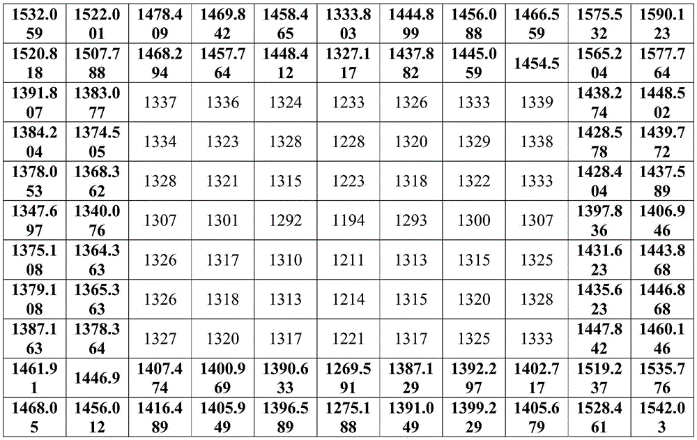
如表1所示为三维相机获取了距离校准平面为0.6米时的第一深度图像中的部分像素相位值,表中的数值为第一深度图像中各像素点的相位值。As shown in Table 1, the phase values of some pixels in the first depth image obtained by the 3D camera when the distance from the calibration plane is 0.6 meters, the values in the table are the phase values of each pixel in the first depth image.
表1Table 1
步骤S2、获取所述三维相机与所述校准平面的距离为测试距离时各像素点的第二相位值,得到用所述第二相位值表示的第二深度图像,所述第二深度图像中包括平面物体图像区域和非平面物体图像区域。Step S2. Obtain the second phase value of each pixel point when the distance between the 3D camera and the calibration plane is the test distance, and obtain a second depth image represented by the second phase value. In the second depth image Including planar object image area and non-planar object image area.
所述测试距离为三维相机与校准平面之间的距离。在一实施方式中,所述测试距离可以根据三维相机的所要校准的拍摄距离调整为0.6米到3.5米之间的任意距离。对于相同的校准平面,当测试距离超过一预设距离时,获取到的第二深度图像中会包含校准平面的平面物体图像区域和与校准平面所在平面相邻的墙面、天花板、地面等其他非平面物体图像区域。The test distance is the distance between the three-dimensional camera and the calibration plane. In one embodiment, the test distance can be adjusted to any distance between 0.6 meters and 3.5 meters according to the shooting distance of the three-dimensional camera to be calibrated. For the same calibration plane, when the test distance exceeds a preset distance, the obtained second depth image will include the plane object image area of the calibration plane and the walls, ceilings, floors, etc. adjacent to the plane where the calibration plane is located. Non-planar object image regions.
在本发明一实施方式中,所述三维相机所要校准的测试距离为1.2米。当测试距离为1.2米是获取的第二深度图像中包含了校准平面的平面图像区域和与校准平面所在平面相邻的墙面、天花板、地面等其他非平面物体图像区域。所述三维相机获取了距离校准平面为1.2米时的第二深度图像中的各像素相位值,如表2所示第二深度图像部分像素的相位值。In one embodiment of the present invention, the test distance to be calibrated for the 3D camera is 1.2 meters. When the test distance is 1.2 meters, the obtained second depth image includes the planar image area of the calibration plane and the image areas of other non-planar objects such as walls, ceilings, and floors adjacent to the plane where the calibration plane is located. The three-dimensional camera acquires the phase values of each pixel in the second depth image when the distance from the calibration plane is 1.2 meters, as shown in Table 2, the phase values of some pixels in the second depth image.
表2Table 2
步骤S3、截取所述第二深度图像中平面物体图像区域像素点的相位值,并删除非平面物体图像区域像素点的相位值。Step S3, intercepting the phase values of the pixels in the image area of the planar object in the second depth image, and deleting the phase values of the pixels in the image area of the non-planar object.
在本发明一实施方式中,截取所述第二深度图像中平面物体图像区域像素点的相位值的方法可以包括:In an embodiment of the present invention, the method for intercepting the phase value of the pixel point in the image area of the planar object in the second depth image may include:
在预设数据库中查找与所述测试距离对应的平面物体图像区域的像素范围,根据所述像素范围在第二深度图像中将相同像素范围标记为平面物体图像区域像素点,并将所述第二深度图像中平面物体图像区域像素点以外的像素点标记为非平面物体图像区域像素点;Find the pixel range of the plane object image region corresponding to the test distance in the preset database, mark the same pixel range as the pixel point of the plane object image region in the second depth image according to the pixel range, and set the pixel range of the second depth image. Pixels other than the pixels in the image area of the planar object in the two-depth image are marked as pixels in the image area of the non-planar object;
其中,所述数据库中存储了不同测试距离时,深度图像中平面物体图像区域范围。Wherein, the database stores the area range of the planar object image in the depth image at different test distances.
举例而言,例如当测量距离为1.2米时,在数据库中查找测量距离为1.2米对应的平面物体图像区域的范围为200×300,以第二深度图像的几何中心分别向上下左右四个方向按照所述平面物体图像区域的范围查找所述平面物体图像区域像素点的相位值,并删除非平面物体图像区域像素点的相位值,由此得到如表3所示的第二深度图像中的平面物体图像区域的部分像素的相位值,由于一张深度图像中像素点数量巨大,为了方便说明,本实施例表格中仅截取包括平面物体图像区域和非平面物体图像区域的部分像素值作为举例说明。表3中的空格区域表示已经删除掉相位值的非平面物体图像区域的像素点的位置,所述平面物体图像区域即为校准平面所在平面的部分,For example, when the measurement distance is 1.2 meters, the range of the image area of the plane object corresponding to the measurement distance of 1.2 meters is searched in the database. Find the phase value of the pixel point in the planar object image region according to the scope of the planar object image region, and delete the phase value of the pixel point in the non-planar object image region, thus obtaining the second depth image as shown in Table 3. The phase values of some pixels in the image area of the planar object, due to the huge number of pixels in a depth image, for the convenience of illustration, only some pixel values including the image area of the planar object and the image area of the non-planar object are intercepted in the table of this embodiment as an example illustrate. The blank area in Table 3 represents the position of the pixels of the non-planar object image area whose phase value has been deleted, and the planar object image area is the part of the plane where the calibration plane is located,
表3table 3
步骤S4、根据所述平面物体图像区域像素点的相位值和所述第一深度图像像素点的相位值计算并输出所述非平面物体图像区域像素点的预测相位值。Step S4. Calculate and output the predicted phase value of the pixel in the non-planar object image area according to the phase value of the pixel in the planar object image area and the phase value of the pixel in the first depth image.
在本发明一实施方式中,所述根据所述平面物体图像区域像素点的相位值和第一深度图像像素点的相位值计算并输出所述非平面物体图像区域像素点的预测相位值可以包括:In an embodiment of the present invention, the calculating and outputting the predicted phase value of the pixel in the non-planar object image area according to the phase value of the pixel in the planar object image area and the phase value of the pixel in the first depth image may include :
在第一深度图像中查找与平面物体图像区域像素点位置相对应的像素点的相位值。The phase value of the pixel point corresponding to the pixel point position in the image area of the planar object is searched in the first depth image.
将平面物体图像区域中各像素点的相位值减去第一深度图像中对应位置的各像素点的相位值,得到由所述相位值的差值构成的差值相位信息图,例如将表3中的相位值减去表1中对应区域的相位值,得到表4由所述相位值的差值构成的部分差值相位信息图。Subtract the phase value of each pixel point in the corresponding position in the first depth image from the phase value of each pixel point in the plane object image area to obtain a difference phase information map composed of the difference of the phase value, for example, Table 3 Subtract the phase value in the corresponding area in Table 1 from the phase value in Table 1 to obtain the partial difference phase information diagram in Table 4 composed of the difference of the phase value.
表4Table 4
将所述差值相位信息图中各像素点的差值相位值分别除以所述差值相位信息图的几何中心对应的相位值,得到由非平面物体图像区域各像素点的比值相位值构成的非平面物体图像区域的比值相位信息图。如表4所示所述差值相位信息图的几何中心对应的相位值为602,将表中其他像素点的相位值分别除以几何中心对应的相位值602,得到如表5所示的部分像素的比值相位信息图。Divide the difference phase value of each pixel in the difference phase information map by the phase value corresponding to the geometric center of the difference phase information map to obtain the ratio phase value of each pixel in the non-planar object image area. Ratio-phase information map of non-planar object image regions of . As shown in Table 4, the phase value corresponding to the geometric center of the difference phase information graph is 602, and the phase values of other pixels in the table are respectively divided by the phase value 602 corresponding to the geometric center to obtain the part shown in Table 5 Ratio-phase information map of pixels.
表5table 5
根据所述非平面物体图像区域中各像素点的比值相位值采用预设的拟合算法拟合出第二深度图像中非平面物体图像区域中各像素点的比值相位值。The ratio phase value of each pixel in the non-planar object image area in the second depth image is fitted by using a preset fitting algorithm according to the ratio phase value of each pixel in the non-planar object image area.
其中,根据所述非平面物体图像区域中各像素点的比值相位值采用预设的拟合算法拟合出第二深度图像中非平面物体图像区域中各像素点的比值相位值的步骤可以包括:Wherein, the step of fitting the ratio phase value of each pixel in the non-planar object image area in the second depth image by using a preset fitting algorithm according to the ratio phase value of each pixel in the non-planar object image area may include :
以所述比值相位信息图的几何中心的像素点作为原点坐标,沿水平和竖直方向建立二维空间直角坐标系,如图4是校准三维相机深度的比值深度信息图中直角坐标示意图所示,其中,所述坐标原点的比值相位值为1。沿所述直角坐标轴中心点原点坐标分别沿横、纵坐标轴向四个方向获取非平面物体图像区域内位于横、纵坐标轴上的四组比值相位值分别为{1.11628,1.10631,1.09967,1},{1,1.08970,1.09302,1.10133},{1.02326,1.01661,1.01495,1},{1,1.02658,1.02658,1.03821},分别选取这四组数据采用非线性拟合的方式,拟合出非平面物体图像区域图像中横纵坐标位置的比值相位,如表6所示,是拟合出来的非平面物体图像区域中横纵坐标位置部分像素点的相位值,表6中加粗部分的相位值为横纵坐标轴上的比值相位值。Taking the pixel point of the geometric center of the ratio phase information map as the origin coordinates, a two-dimensional spatial Cartesian coordinate system is established along the horizontal and vertical directions, as shown in Figure 4, which is a schematic diagram of the Cartesian coordinates in the ratio depth information map for calibrating the three-dimensional camera depth , wherein the ratio phase value of the coordinate origin is 1. The coordinates of the origin of the center point of the rectangular coordinate axis are respectively obtained along the four directions of the horizontal and vertical coordinate axes, and the four groups of ratio phase values located on the horizontal and vertical axes in the non-planar object image area are respectively {1.11628, 1.10631, 1.09967, 1}, {1, 1.08970, 1.09302, 1.10133}, {1.02326, 1.01661, 1.01495, 1}, {1, 1.02658, 1.02658, 1.03821}, respectively select these four sets of data by nonlinear fitting, and fit The ratio phase of the abscissa and ordinate positions in the non-planar object image area image, as shown in Table 6, is the phase value of the pixels at the abscissa and ordinate positions in the fitted non-planar object image area, and the bold part in Table 6 The phase value is the ratio phase value on the horizontal and vertical axes.
表6Table 6

分别将非平面物体图像区域中横坐标中的每一点与非平面物体图像区域中纵坐标中的每一点进行相乘运算,得到非平面物体图像区域对应位置的比值相位值。如表7所示表中加粗部分的相位值为利用非平面物体图像区域中横坐标中的每一点与非平面物体图像区域中纵坐标中的每一点进行相乘运算得到的所述非平面物体图像区域的比值相位值。Each point in the abscissa of the non-planar object image area is multiplied by each point in the ordinate of the non-planar object image area to obtain the ratio phase value of the corresponding position of the non-planar object image area. As shown in Table 7, the phase value of the bold part in the table is obtained by multiplying each point in the abscissa in the non-planar object image area with each point in the ordinate in the non-planar object image area. The ratio phase value of the object image region.
表7Table 7

将所述非平面物体图像区域的比值相位信息进行逆运算,得到非平面物体图像区域的预测相位值。Inverse operation is performed on the ratio phase information of the non-planar object image region to obtain the predicted phase value of the non-planar object image region.
其中,将所述非平面物体图像区域的比值相位信息进行逆运算,得到非平面物体图像区域的预测相位值的步骤可以包括:Wherein, performing an inverse operation on the ratio phase information of the non-planar object image region to obtain the predicted phase value of the non-planar object image region may include:
将非平面物体图像区域的各像素点的比值相位值乘以所述差值相位信息图的几何中心的差值相位值,得到非平面物体图像区域中各像素点的差值相位值。例如将表7中各像素点的相位值分别乘以如表4所述差值相位信息图的几何中心的差值相位值602,得到非平面物体图像区域中各像素点的差值相位值;Multiplying the ratio phase value of each pixel in the non-planar object image area by the difference phase value of the geometric center of the difference phase information map to obtain the difference phase value of each pixel in the non-planar object image area. For example, the phase value of each pixel in Table 7 is multiplied by the difference phase value 602 of the geometric center of the difference phase information map as described in Table 4, to obtain the difference phase value of each pixel in the non-planar object image region;
将所述非平面物体图像区域中各像素点的差值相位值加上所述第一深度图像与所述非平面物体图像区域对应位置的像素点相位值,得到所述非平面物体图像区域中各像素点的预测相位值。Adding the difference phase value of each pixel in the non-planar object image area to the phase value of the pixel point corresponding to the first depth image and the non-planar object image area, to obtain the non-planar object image area The predicted phase value of each pixel.
整合并输出所述非平面物体图像区域的各像素点的预测相位值与所述平面物体图像区域中各像素点的相位值。获取所述非平面物体图像区域中各像素点的预测相位值,将所述预测相位值按照非平面物体图像区域像素点的位置对应存储于所述第二深度图像,其中所述校准后的第二深度图像中包含平面物体图像区域像素点的相位值和非平面物体图像区域像素点的预测相位值,进而使用校准后的第二深度图像中的相位值校正深度。如表8所示,所述校准后的第二深度图像中部分像素点的相位值,其中所述校准后的第二深度图像中包含平面物体图像区域像素点的相位值和非平面物体图像区域像素点的预测相位值。如表8中所示,黑色加粗部分的数字是非平面物体图像区域像素点的预测相位值在,中间区域未加粗的数字是平面物体图像区域像素点的相位值。Integrating and outputting the predicted phase value of each pixel in the non-planar object image area and the phase value of each pixel in the planar object image area. Obtain the predicted phase value of each pixel in the non-planar object image area, and store the predicted phase value in the second depth image according to the position of the pixel in the non-planar object image area, wherein the calibrated first The two-depth image includes the phase values of the pixels in the image area of the planar object and the predicted phase values of the pixels in the image area of the non-planar object, and then uses the phase values in the calibrated second depth image to correct the depth. As shown in Table 8, the phase values of some pixels in the calibrated second depth image, wherein the calibrated second depth image includes the phase values of the pixels in the planar object image area and the non-planar object image area The predicted phase value of the pixel. As shown in Table 8, the numbers in the black bold part are the predicted phase values of the pixels in the non-planar object image area, and the unbold numbers in the middle area are the phase values of the pixels in the planar object image area.
表8Table 8
步骤S5、根据非平面物体图像区域像素点的所述预测相位值和所述平面物体图像区域像素点的相位值校准所述三维相机拍摄图像的深度信息。Step S5. Calibrate the depth information of the image captured by the 3D camera according to the predicted phase value of the pixel point in the non-planar object image area and the phase value of the pixel point in the planar object image area.
在本发明一实施方式中,根据预测第二深度图像中非平面物体图像区域像素点的所述预测相位值和所述平面物体图像区域像素点的相位值如表8所示,根据所述相位值,利用三维相机相位值和深度值的对应关系得到所述三维相机拍摄图像的深度信息。所述根据三维相机相位值和深度值的对应关系为现有技术,在此不再赘述。In an embodiment of the present invention, according to the predicted phase value of the pixel point in the non-planar object image area in the predicted second depth image and the phase value of the pixel point in the planar object image area as shown in Table 8, according to the phase value, using the corresponding relationship between the phase value and the depth value of the three-dimensional camera to obtain the depth information of the image captured by the three-dimensional camera. The corresponding relationship between the phase value and the depth value according to the 3D camera is the prior art, and will not be repeated here.
上述图3详细介绍了本发明的校准三维相机深度的方法,下面结合第5-6图,对实现所述校准三维相机深度的方法的软件装置的功能模块以及实现所述校准三维相机深度的方法的硬件装置架构进行介绍。The above-mentioned Fig. 3 has introduced in detail the method for calibrating the depth of the three-dimensional camera of the present invention. In conjunction with Figs. 5-6, the functional modules of the software device for realizing the method for calibrating the depth of the three-dimensional camera and the method for realizing the method for calibrating the depth of the three-dimensional camera The hardware device architecture is introduced.
应所述了解,所述实施例仅为说明之用,在专利申请范围上并不受此结构的限制。It should be understood that the embodiments are only for illustration, and the scope of the patent application is not limited by this structure.
实施例三Embodiment Three
图5为本发明校准三维相机深度的装置较佳实施例的结构图。FIG. 5 is a structural diagram of a preferred embodiment of the device for calibrating the depth of a three-dimensional camera according to the present invention.
在一些实施例中,校准三维相机深度的装置10运行于计算机装置中。所述计算机装置通过网络连接了多个用户终端。所述校准三维相机深度的装置10可以包括多个由程序代码段所组成的功能模块。所述校准三维相机深度的装置10中的各个程序段的程序代码可以存储于计算机装置的存储器中,并由所述至少一个处理器所执行,以实现校准三维相机深度的功能。In some embodiments, the
本实施例中,所述校准三维相机深度的装置10根据其所执行的功能,可以被划分为多个功能模块。参阅图5所示,所述功能模块可以包括:第一获取模块101、第二获取模块102、截取模块103、计算模块104、校准模块105。本发明所称的模块是指一种能够被至少一个处理器所执行并且能够完成固定功能的一系列计算机程序段,其存储在存储器中。在本实施例中,关于各模块的功能将在后续的实施例中详述。In this embodiment, the
第一获取模块101,用于获取待校准的三维相机与校准平面的距离为标准距离时各像素点的第一相位值,得到使用所述第一相位值表示的第一深度图像。The
所述校准平面是材质或反射率一致的平面。所述标准距离为三维相机与所述校准平面之间的距离。当所述三维相机与所述校准平面为标准距离时,所述三维相机获取到的图像中仅包含平面物体图像区域,不包含非平面图像区域,所述非平面物体图像区域为与所述标准平面相邻的墙面、天花、地板等。The calibration plane is a plane with consistent material or reflectivity. The standard distance is the distance between the 3D camera and the calibration plane. When the three-dimensional camera is at a standard distance from the calibration plane, the image acquired by the three-dimensional camera only includes a planar object image area, and does not include a non-planar object image area, and the non-planar object image area is the same as the standard Plane adjacent walls, ceilings, floors, etc.
如表1所示为三维相机获取了距离校准平面为0.6米时的第一深度图像中的部分像素相位值,表中的数值为第一深度图像中各像素点的相位值。As shown in Table 1, the phase values of some pixels in the first depth image obtained by the 3D camera when the distance from the calibration plane is 0.6 meters, the values in the table are the phase values of each pixel in the first depth image.
第二获取模块102,用于获取所述三维相机与所述校准平面的距离为测试距离时各像素点的第二相位值,得到用所述第二相位值表示的第二深度图像,所述第二深度图像中包括平面物体图像区域和非平面物体图像区域。The
所述测试距离为三维相机与校准平面之间的距离。在一实施方式中,所述测试距离可以根据三维相机的所要校准的拍摄距离调整为0.6米到3.5米之间的任意距离。对于相同的校准平面,当测试距离超过一预设距离时,获取到的第二深度图像中会包含校准平面的平面物体图像区域和与校准平面所在平面相邻的墙面、天花板、地面等其他非平面物体图像区域。The test distance is the distance between the three-dimensional camera and the calibration plane. In one embodiment, the test distance can be adjusted to any distance between 0.6 meters and 3.5 meters according to the shooting distance of the three-dimensional camera to be calibrated. For the same calibration plane, when the test distance exceeds a preset distance, the obtained second depth image will include the plane object image area of the calibration plane and the walls, ceilings, floors, etc. adjacent to the plane where the calibration plane is located. Non-planar object image regions.
在本发明一实施方式中,所述三维相机所要校准的测试距离为1.2米。当测试距离为1.2米是获取的第二深度图像中包含了校准平面的平面图像区域和与校准平面所在平面相邻的墙面、天花板、地面等其他非平面物体图像区域。所述三维相机获取了距离校准平面为1.2米时的第二深度图像中的各像素相位值,如表2所示第二深度图像部分像素的相位值。In one embodiment of the present invention, the test distance to be calibrated for the 3D camera is 1.2 meters. When the test distance is 1.2 meters, the obtained second depth image includes the planar image area of the calibration plane and the image areas of other non-planar objects such as walls, ceilings, and floors adjacent to the plane where the calibration plane is located. The three-dimensional camera acquires the phase values of each pixel in the second depth image when the distance from the calibration plane is 1.2 meters, as shown in Table 2, the phase values of some pixels in the second depth image.
截取模块103,用于截取所述第二深度图像中平面物体图像区域像素点的相位值,并删除非平面物体图像区域像素点的相位值。The intercepting
在本发明一实施方式中,截取所述第二深度图像中平面物体图像区域像素点的相位值的方法可以包括:In an embodiment of the present invention, the method for intercepting the phase value of the pixel point in the image area of the planar object in the second depth image may include:
在预设数据库中查找与所述测试距离对应的平面物体图像区域的像素范围,根据所述像素范围在第二深度图像中将相同像素范围标记为平面物体图像区域像素点,并将所述第二深度图像中平面物体图像区域像素点以外的像素点标记为非平面物体图像区域像素点;Find the pixel range of the plane object image region corresponding to the test distance in the preset database, mark the same pixel range as the pixel point of the plane object image region in the second depth image according to the pixel range, and set the pixel range of the second depth image. Pixels other than the pixels in the image area of the planar object in the two-depth image are marked as pixels in the image area of the non-planar object;
其中,所述数据库中存储了不同测试距离时,深度图像中平面物体图像区域范围。Wherein, the database stores the area range of the planar object image in the depth image at different test distances.
举例而言,例如当测量距离为1.2米时,在数据库中查找测量距离为1.2米对应的平面物体图像区域的范围为200×300,以第二深度图像的几何中心分别向上下左右四个方向按照所述平面物体图像区域的范围查找所述平面物体图像区域像素点的相位值,并删除非平面物体图像区域像素点的相位值,由此得到如表3所示的第二深度图像中的平面物体图像区域的部分像素的相位值,由于一张深度图像中像素点数量巨大,为了方便说明,本实施例表格中仅截取包括平面物体图像区域和非平面物体图像区域的部分像素值作为举例说明。表3中的空格区域表示已经删除掉相位值的非平面物体图像区域的像素点的位置,所述平面物体图像区域即为校准平面所在平面的部分。For example, when the measurement distance is 1.2 meters, the range of the image area of the plane object corresponding to the measurement distance of 1.2 meters is searched in the database. Find the phase value of the pixel point in the planar object image region according to the scope of the planar object image region, and delete the phase value of the pixel point in the non-planar object image region, thus obtaining the second depth image as shown in Table 3. The phase values of some pixels in the image area of the planar object, due to the huge number of pixels in a depth image, for the convenience of illustration, only some pixel values including the image area of the planar object and the image area of the non-planar object are intercepted in the table of this embodiment as an example illustrate. The blank area in Table 3 indicates the position of the pixels of the non-planar object image area whose phase value has been deleted, and the planar object image area is the part of the plane where the calibration plane is located.
计算模块104,用于根据所述平面物体图像区域像素点的相位值和第一深度图像像素点的相位值计算并输出所述非平面物体图像区域像素点的预测相位值。The calculating
在本发明一实施方式中,所述根据所述平面物体图像区域像素点的相位值和第一深度图像像素点的相位值计算并输出所述非平面物体图像区域像素点的预测相位值可以包括:In an embodiment of the present invention, the calculating and outputting the predicted phase value of the pixel in the non-planar object image area according to the phase value of the pixel in the planar object image area and the phase value of the pixel in the first depth image may include :
在第一深度图像中查找与平面物体图像区域像素点位置相对应的像素点的相位值。The phase value of the pixel point corresponding to the pixel point position in the image area of the planar object is searched in the first depth image.
将平面物体图像区域中各像素点的相位值减去第一深度图像中对应位置的各像素点的相位值,得到由所述相位值的差值构成的差值相位信息图,例如将表3中的相位值减去表1中对应区域的相位值,得到表4由所述相位值的差值构成的部分差值相位信息图。Subtract the phase value of each pixel point in the corresponding position in the first depth image from the phase value of each pixel point in the plane object image area to obtain a difference phase information map composed of the difference of the phase value, for example, Table 3 Subtract the phase value in the corresponding area in Table 1 from the phase value in Table 1 to obtain the partial difference phase information diagram in Table 4 composed of the difference of the phase value.
将所述差值相位信息图中各像素点的差值相位值分别除以所述差值相位信息图的几何中心对应的相位值,得到由非平面物体图像区域各像素点的比值相位值构成的非平面物体图像区域的比值相位信息图。如表4所示所述差值相位信息图的几何中心对应的相位值为602,将表中其他像素点的相位值分别除以几何中心对应的相位值602,得到如表5所示的部分像素的比值相位信息图。Divide the difference phase value of each pixel in the difference phase information map by the phase value corresponding to the geometric center of the difference phase information map to obtain the ratio phase value of each pixel in the non-planar object image area. Ratio-phase information map of non-planar object image regions of . As shown in Table 4, the phase value corresponding to the geometric center of the difference phase information graph is 602, and the phase values of other pixels in the table are respectively divided by the phase value 602 corresponding to the geometric center to obtain the part shown in Table 5 Ratio-phase information map of pixels.
根据所述非平面物体图像区域中各像素点的比值相位值采用预设的拟合算法拟合出第二深度图像中非平面物体图像区域中各像素点的比值相位值。The ratio phase value of each pixel in the non-planar object image area in the second depth image is fitted by using a preset fitting algorithm according to the ratio phase value of each pixel in the non-planar object image area.
其中,根据所述非平面物体图像区域中各像素点的比值相位值采用预设的拟合算法拟合出第二深度图像中非平面物体图像区域中各像素点的比值相位值的步骤可以包括:Wherein, the step of fitting the ratio phase value of each pixel in the non-planar object image area in the second depth image by using a preset fitting algorithm according to the ratio phase value of each pixel in the non-planar object image area may include :
以所述比值相位信息图的几何中心的像素点作为原点坐标,沿水平和竖直方向建立二维空间直角坐标系,如图4是校准三维相机深度的比值深度信息图中直角坐标示意图所示,其中,所述坐标原点的比值相位值为1。沿所述直角坐标轴中心点原点坐标分别沿横、纵坐标轴向四个方向获取非平面物体图像区域内位于横、纵坐标轴上的四组比值相位值分别为{1.11628,1.10631,1.09967,1},{1,1.08970,1.09302,1.10133},{1.02326,1.01661,1.01495,1},{1,1.02658,1.02658,1.03821},分别选取这四组数据采用非线性拟合的方式,拟合出非平面物体图像区域图像中横纵坐标位置的比值相位,如表6所示,是拟合出来的非平面物体图像区域中横纵坐标位置部分像素点的相位值,表6中加粗部分的相位值为横纵坐标轴上的比值相位值。Taking the pixel point of the geometric center of the ratio phase information map as the origin coordinates, a two-dimensional spatial Cartesian coordinate system is established along the horizontal and vertical directions, as shown in Figure 4, which is a schematic diagram of the Cartesian coordinates in the ratio depth information map for calibrating the three-dimensional camera depth , wherein the ratio phase value of the coordinate origin is 1. The coordinates of the origin of the center point of the rectangular coordinate axis are respectively obtained along the four directions of the horizontal and vertical coordinate axes, and the four groups of ratio phase values located on the horizontal and vertical axes in the non-planar object image area are respectively {1.11628, 1.10631, 1.09967, 1}, {1, 1.08970, 1.09302, 1.10133}, {1.02326, 1.01661, 1.01495, 1}, {1, 1.02658, 1.02658, 1.03821}, respectively select these four sets of data by nonlinear fitting, and fit The ratio phase of the abscissa and ordinate positions in the non-planar object image area image, as shown in Table 6, is the phase value of the pixels at the abscissa and ordinate positions in the fitted non-planar object image area, and the bold part in Table 6 The phase value is the ratio phase value on the horizontal and vertical axes.
分别将非平面物体图像区域中横坐标中的每一点与非平面物体图像区域中纵坐标中的每一点进行相乘运算,得到非平面物体图像区域对应位置的比值相位值。如表7所示表中加粗部分的相位值为利用非平面物体图像区域中横坐标中的每一点与非平面物体图像区域中纵坐标中的每一点进行相乘运算得到的所述非平面物体图像区域的比值相位值。Each point in the abscissa of the non-planar object image area is multiplied by each point in the ordinate of the non-planar object image area to obtain the ratio phase value of the corresponding position of the non-planar object image area. As shown in Table 7, the phase value of the bold part in the table is obtained by multiplying each point in the abscissa in the non-planar object image area with each point in the ordinate in the non-planar object image area. The ratio phase value of the object image region.
将所述非平面物体图像区域的比值相位信息进行逆运算,得到非平面物体图像区域的预测相位值。Inverse operation is performed on the ratio phase information of the non-planar object image region to obtain the predicted phase value of the non-planar object image region.
其中,将所述非平面物体图像区域的比值相位信息进行逆运算,得到非平面物体图像区域的预测相位值的步骤可以包括:Wherein, performing an inverse operation on the ratio phase information of the non-planar object image region to obtain the predicted phase value of the non-planar object image region may include:
将非平面物体图像区域的各像素点的比值相位值乘以所述差值相位信息图的几何中心的差值相位值,得到非平面物体图像区域中各像素点的差值相位值。例如将表7中各像素点的相位值分别乘以如表4所述差值相位信息图的几何中心的差值相位值602,得到非平面物体图像区域中各像素点的差值相位值;Multiplying the ratio phase value of each pixel in the non-planar object image area by the difference phase value of the geometric center of the difference phase information map to obtain the difference phase value of each pixel in the non-planar object image area. For example, the phase value of each pixel in Table 7 is multiplied by the difference phase value 602 of the geometric center of the difference phase information map as described in Table 4, to obtain the difference phase value of each pixel in the non-planar object image region;
将所述非平面物体图像区域中各像素点的差值相位值加上所述第一深度图像与所述非平面物体图像区域对应位置的像素点相位值,得到所述非平面物体图像区域中各像素点的预测相位值。Adding the difference phase value of each pixel in the non-planar object image area to the phase value of the pixel point corresponding to the first depth image and the non-planar object image area, to obtain the non-planar object image area The predicted phase value of each pixel.
整合并输出所述非平面物体图像区域的各像素点的预测相位值与所述平面物体图像区域中各像素点的相位值。获取所述非平面物体图像区域中各像素点的预测相位值,将所述预测相位值按照非平面物体图像区域像素点的位置对应存储于所述第二深度图像,其中所述校准后的第二深度图像中包含平面物体图像区域像素点的相位值和非平面物体图像区域像素点的预测相位值,进而使用校准后的第二深度图像中的相位值校正深度。如表8所示,所述校准后的第二深度图像中部分像素点的相位值,其中所述校准后的第二深度图像中包含平面物体图像区域像素点的相位值和非平面物体图像区域像素点的预测相位值。如表8中所示,黑色加粗部分的数字是非平面物体图像区域像素点的预测相位值在,中间区域未加粗的数字是平面物体图像区域像素点的相位值。Integrating and outputting the predicted phase value of each pixel in the non-planar object image area and the phase value of each pixel in the planar object image area. Obtain the predicted phase value of each pixel in the non-planar object image area, and store the predicted phase value in the second depth image according to the position of the pixel in the non-planar object image area, wherein the calibrated first The two-depth image includes the phase values of the pixels in the image area of the planar object and the predicted phase values of the pixels in the image area of the non-planar object, and then uses the phase values in the calibrated second depth image to correct the depth. As shown in Table 8, the phase values of some pixels in the calibrated second depth image, wherein the calibrated second depth image includes the phase values of the pixels in the planar object image area and the non-planar object image area The predicted phase value of the pixel. As shown in Table 8, the numbers in the black bold part are the predicted phase values of the pixels in the non-planar object image area, and the unbold numbers in the middle area are the phase values of the pixels in the planar object image area.
校准模块105,用于根据非平面物体图像区域像素点的所述预测相位值和所述平面物体图像区域像素点的相位值校准所述三维相机拍摄图像的深度信息。The
在本发明一实施方式中,根据预测第二深度图像中非平面物体图像区域像素点的所述预测相位值和所述平面物体图像区域像素点的相位值如表8所示,根据所述相位值,利用三维相机相位值和深度值的对应关系得到所述三维相机拍摄图像的深度信息。所述根据三维相机相位值和深度值的对应关系为现有技术,在此不再赘述。In an embodiment of the present invention, according to the predicted phase value of the pixel point in the non-planar object image area in the predicted second depth image and the phase value of the pixel point in the planar object image area as shown in Table 8, according to the phase value, using the corresponding relationship between the phase value and the depth value of the three-dimensional camera to obtain the depth information of the image captured by the three-dimensional camera. The corresponding relationship between the phase value and the depth value according to the 3D camera is the prior art, and will not be repeated here.
实施例四Embodiment Four
图6为本发明计算机装置较佳实施例的示意图。FIG. 6 is a schematic diagram of a preferred embodiment of the computer device of the present invention.
所述计算机装置1包括存储器20、处理器30以及存储在所述存储器20中并可在所述处理器30上运行的计算机程序40,例如校准三维相机深度的程序。所述处理器30执行所述计算机程序40时实现上述校准三维相机深度的方法实施例中的步骤,例如图3所示的步骤S1~S5。或者,所述处理器30执行所述计算机程序40时实现上述校准三维相机深度的装置实施例中各模块/单元的功能,例如图5中的单元101-105。The
示例性的,所述计算机程序40可以被分割成一个或多个模块/单元,所述一个或者多个模块/单元被存储在所述存储器20中,并由所述处理器30执行,以完成本发明。所述一个或多个模块/单元可以是能够完成特定功能的一系列计算机程序指令段,所述指令段用于描述所述计算机程序40在所述计算机装置1中的执行过程。例如,所述计算机程序40可以被分割成图5中的第一获取模块101、第二获取模块102、截取模块103、计算模块104、校准模块105。Exemplarily, the
所述计算机装置1可以是桌上型计算机、笔记本、掌上电脑及云端服务器等计算设备。本领域技术人员可以理解,所述示意图仅仅是计算机装置1的示例,并不构成对计算机装置1的限定,可以包括比图示更多或更少的部件,或者组合某些部件,或者不同的部件,例如所述计算机装置1还可以包括输入输出设备、网络接入设备、总线等。The
所称处理器30可以是中央处理单元(Central Processing Unit,CPU),还可以是其他通用处理器、数字信号处理器(Digital Signal Processor,DSP)、专用集成电路(Application Specific Integrated Circuit,ASIC)、现成可编程门阵列(Field-Programmable Gate Array,FPGA)或者其他可编程逻辑器件、分立门或者晶体管逻辑器件、分立硬件组件等。通用处理器可以是微处理器或者所述处理器30也可以是任何常规的处理器等,所述处理器30是所述计算机装置1的控制中心,利用各种接口和线路连接整个计算机装置1的各个部分。The so-called
所述存储器20可用于存储所述计算机程序40和/或模块/单元,所述处理器30通过运行或执行存储在所述存储器20内的计算机程序和/或模块/单元,以及调用存储在存储器20内的数据,实现所述计算机装置1的各种功能。所述存储器20可主要包括存储程序区和存储数据区,其中,存储程序区可存储操作系统、至少一个功能所需的应用程序(比如声音播放功能、图像播放功能等)等;存储数据区可存储根据计算机装置1的使用所创建的数据(比如音频数据、电话本等)等。此外,存储器20可以包括高速随机存取存储器,还可以包括非易失性存储器,例如硬盘、内存、插接式硬盘,智能存储卡(Smart Media Card,SMC),安全数字(Secure Digital,SD)卡,闪存卡(Flash Card)、至少一个磁盘存储器件、闪存器件、或其他易失性固态存储器件。The
所述计算机装置1集成的模块/单元如果以软件功能单元的形式实现并作为独立的产品销售或使用时,可以存储在一个计算机可读取存储介质中。基于这样的理解,本发明实现上述实施例方法中的全部或部分流程,也可以通过计算机程序来指令相关的硬件来完成,所述的计算机程序可存储于一计算机可读存储介质中,所述计算机程序在被处理器执行时,可实现上述各个方法实施例的步骤。其中,所述计算机程序包括计算机程序代码,所述计算机程序代码可以为源代码形式、对象代码形式、可执行文件或某些中间形式等。所述计算机可读介质可以包括:能够携带所述计算机程序代码的任何实体或装置、记录介质、U盘、移动硬盘、磁碟、光盘、计算机存储器、只读存储器(ROM,Read-Only Memory)、随机存取存储器(RAM,Random Access Memory)、电载波信号、电信信号以及软件分发介质等。需要说明的是,所述计算机可读介质包含的内容可以根据司法管辖区内立法和专利实践的要求进行适当的增减,例如在某些司法管辖区,根据立法和专利实践,计算机可读介质不包括电载波信号和电信信号。If the integrated modules/units of the
在本发明所提供的几个实施例中,应所述理解到,所揭露的计算机装置和方法,可以通过其它的方式实现。例如,以上所描述的计算机装置实施例仅仅是示意性的,例如,所述单元的划分,仅仅为一种逻辑功能划分,实际实现时可以有另外的划分方式。In the several embodiments provided by the present invention, it should be understood that the disclosed computer device and method can be implemented in other ways. For example, the computer device embodiments described above are only illustrative. For example, the division of the units is only a logical function division, and there may be other division methods in actual implementation.
另外,在本发明各个实施例中的各功能单元可以集成在相同处理单元中,也可以是各个单元单独物理存在,也可以两个或两个以上单元集成在相同单元中。上述集成的单元既可以采用硬件的形式实现,也可以采用硬件加软件功能模块的形式实现。In addition, each functional unit in each embodiment of the present invention may be integrated into the same processing unit, or each unit may physically exist separately, or two or more units may be integrated into the same unit. The above-mentioned integrated units can be implemented in the form of hardware, or in the form of hardware plus software function modules.
对于本领域技术人员而言,显然本发明不限于上述示范性实施例的细节,而且在不背离本发明的精神或基本特征的情况下,能够以其他的具体形式实现本发明。因此,无论从哪一点来看,均应将实施例看作是示范性的,而且是非限制性的,本发明的范围由所附权利要求而不是上述说明限定,因此旨在将落在权利要求的等同要件的含义和范围内的所有变化涵括在本发明内。不应将权利要求中的任何附图标记视为限制所涉及的权利要求。此外,显然“包括”一词不排除其他单元或步骤,单数不排除复数。计算机装置权利要求中陈述的多个单元或计算机装置也可以由同一个单元或计算机装置通过软件或者硬件来实现。第一,第二等词语用来表示名称,而并不表示任何特定的顺序。It will be apparent to those skilled in the art that the invention is not limited to the details of the above-described exemplary embodiments, but that the invention can be embodied in other specific forms without departing from the spirit or essential characteristics of the invention. Accordingly, the embodiments should be regarded in all points of view as exemplary and not restrictive, the scope of the invention being defined by the appended claims rather than the foregoing description, and it is therefore intended that the scope of the invention be defined by the appended claims rather than by the foregoing description. All changes within the meaning and range of equivalents of the elements are embraced in the present invention. Any reference sign in a claim should not be construed as limiting the claim concerned. In addition, it is obvious that the word "comprising" does not exclude other elements or steps, and the singular does not exclude the plural. Multiple units or computer devices stated in the computer device claims may also be realized by the same unit or computer device through software or hardware. The words first, second, etc. are used to denote names and do not imply any particular order.
最后应说明的是,以上实施例仅用以说明本发明的技术方案而非限制,尽管参照较佳实施例对本发明进行了详细说明,本领域的普通技术人员应当理解,可以对本发明的技术方案进行修改或等同替换,而不脱离本发明技术方案的精神和范围。Finally, it should be noted that the above embodiments are only used to illustrate the technical solutions of the present invention without limitation. Although the present invention has been described in detail with reference to the preferred embodiments, those of ordinary skill in the art should understand that the technical solutions of the present invention can be Modifications or equivalent replacements can be made without departing from the spirit and scope of the technical solutions of the present invention.
Claims (10)
Priority Applications (3)
| Application Number | Priority Date | Filing Date | Title |
|---|---|---|---|
| CN201910795247.XA CN110673114B (en) | 2019-08-27 | 2019-08-27 | Method and device for calibrating depth of three-dimensional camera, computer device and storage medium |
| TW108131443A TWI736965B (en) | 2019-08-27 | 2019-08-30 | A method and device for calibrating depth of three-dimensional camera, computer device and storage medium |
| US16/681,966 US11043009B2 (en) | 2019-08-27 | 2019-11-13 | Method and device for calibrating depth of 3D camera, and computer device |
Applications Claiming Priority (1)
| Application Number | Priority Date | Filing Date | Title |
|---|---|---|---|
| CN201910795247.XA CN110673114B (en) | 2019-08-27 | 2019-08-27 | Method and device for calibrating depth of three-dimensional camera, computer device and storage medium |
Publications (2)
| Publication Number | Publication Date |
|---|---|
| CN110673114A CN110673114A (en) | 2020-01-10 |
| CN110673114B true CN110673114B (en) | 2023-04-18 |
Family
ID=69075740
Family Applications (1)
| Application Number | Title | Priority Date | Filing Date |
|---|---|---|---|
| CN201910795247.XA Expired - Fee Related CN110673114B (en) | 2019-08-27 | 2019-08-27 | Method and device for calibrating depth of three-dimensional camera, computer device and storage medium |
Country Status (3)
| Country | Link |
|---|---|
| US (1) | US11043009B2 (en) |
| CN (1) | CN110673114B (en) |
| TW (1) | TWI736965B (en) |
Families Citing this family (5)
| Publication number | Priority date | Publication date | Assignee | Title |
|---|---|---|---|---|
| CN111757101B (en) * | 2020-07-15 | 2022-04-08 | 季华实验室 | Line scan camera static calibration device and calibration method |
| CN113465879B (en) * | 2021-08-13 | 2025-01-07 | 北京京东乾石科技有限公司 | Test system and three-dimensional camera test method using the test system |
| CN117218175A (en) * | 2022-06-02 | 2023-12-12 | 鸿海精密工业股份有限公司 | Depth estimation method, device, electronic equipment and storage medium |
| CN115442591B (en) * | 2022-11-04 | 2023-03-24 | 合肥的卢深视科技有限公司 | Camera quality testing method, system, electronic device and storage medium |
| CN116506594B (en) * | 2023-05-22 | 2025-08-26 | 凌云光技术股份有限公司 | Camera accuracy testing method, system and host computer |
Family Cites Families (23)
| Publication number | Priority date | Publication date | Assignee | Title |
|---|---|---|---|---|
| TW521519B (en) * | 1999-11-26 | 2003-02-21 | Sanyo Electric Co | Apparatus and method for converting a two dimensional image to a three dimensional image |
| US8570320B2 (en) * | 2011-01-31 | 2013-10-29 | Microsoft Corporation | Using a three-dimensional environment model in gameplay |
| US9117281B2 (en) * | 2011-11-02 | 2015-08-25 | Microsoft Corporation | Surface segmentation from RGB and depth images |
| US9225959B2 (en) * | 2012-01-10 | 2015-12-29 | Samsung Electronics Co., Ltd. | Method and apparatus for recovering depth value of depth image |
| CN104169970B (en) * | 2012-04-18 | 2018-01-05 | 索尼公司 | For the method and optical system of the depth map for determining image |
| KR101871235B1 (en) * | 2012-06-05 | 2018-06-27 | 삼성전자주식회사 | Depth image generating method and apparatus, depth image processing method and apparatus |
| US20140139632A1 (en) * | 2012-11-21 | 2014-05-22 | Lsi Corporation | Depth imaging method and apparatus with adaptive illumination of an object of interest |
| RU2012154657A (en) * | 2012-12-17 | 2014-06-27 | ЭлЭсАй Корпорейшн | METHODS AND DEVICE FOR COMBINING IMAGES WITH DEPTH GENERATED USING DIFFERENT METHODS FOR FORMING IMAGES WITH DEPTH |
| WO2014160510A2 (en) * | 2013-03-13 | 2014-10-02 | Massachusetts Institute Of Technology | Photometric stereo endoscopy |
| EP2992357A4 (en) * | 2013-04-29 | 2017-01-18 | Nokia Technologies OY | A method and apparatus for fusing distance data from a distance sensing camera with an image |
| US10061028B2 (en) * | 2013-09-05 | 2018-08-28 | Texas Instruments Incorporated | Time-of-flight (TOF) assisted structured light imaging |
| TWI485361B (en) * | 2013-09-11 | 2015-05-21 | Univ Nat Taiwan | Measuring apparatus for three-dimensional profilometry and method thereof |
| CN105323571B (en) * | 2014-06-17 | 2017-09-29 | 立普思股份有限公司 | image phase correction method |
| US9773155B2 (en) * | 2014-10-14 | 2017-09-26 | Microsoft Technology Licensing, Llc | Depth from time of flight camera |
| KR102283423B1 (en) * | 2014-12-18 | 2021-07-30 | 엘지이노텍 주식회사 | Image pick-up apparatus, portable terminal including the same and image pick-up method using the apparatus |
| CN104729429B (en) * | 2015-03-05 | 2017-06-30 | 深圳大学 | A Calibration Method for 3D Topography Measurement System Based on Telecentric Imaging |
| US10250833B2 (en) * | 2015-04-20 | 2019-04-02 | Samsung Electronics Co., Ltd. | Timestamp calibration of the 3D camera with epipolar line laser point scanning |
| US10451740B2 (en) * | 2016-04-26 | 2019-10-22 | Cepton Technologies, Inc. | Scanning lidar systems for three-dimensional sensing |
| WO2018044314A1 (en) * | 2016-09-01 | 2018-03-08 | Duelight Llc | Systems and methods for adjusting focus based on focus target information |
| US10070042B2 (en) * | 2016-12-19 | 2018-09-04 | Intel Corporation | Method and system of self-calibration for phase detection autofocus |
| DE102017126378A1 (en) * | 2017-11-10 | 2019-05-16 | Infineon Technologies Ag | Method for processing a raw image of a time-of-flight camera, image processing device and computer program |
| US10663567B2 (en) * | 2018-05-04 | 2020-05-26 | Microsoft Technology Licensing, Llc | Field calibration of a structured light range-sensor |
| US11500100B2 (en) * | 2019-04-15 | 2022-11-15 | Microsoft Technology Licensing, Llc | Time-of-flight measurements using linear inverse function |
-
2019
- 2019-08-27 CN CN201910795247.XA patent/CN110673114B/en not_active Expired - Fee Related
- 2019-08-30 TW TW108131443A patent/TWI736965B/en not_active IP Right Cessation
- 2019-11-13 US US16/681,966 patent/US11043009B2/en active Active
Also Published As
| Publication number | Publication date |
|---|---|
| US11043009B2 (en) | 2021-06-22 |
| CN110673114A (en) | 2020-01-10 |
| TWI736965B (en) | 2021-08-21 |
| TW202109457A (en) | 2021-03-01 |
| US20210065402A1 (en) | 2021-03-04 |
Similar Documents
| Publication | Publication Date | Title |
|---|---|---|
| CN110673114B (en) | Method and device for calibrating depth of three-dimensional camera, computer device and storage medium | |
| CN111383279B (en) | External parameter calibration method and device and electronic equipment | |
| CN110988849B (en) | Calibration method and device of radar system, electronic equipment and storage medium | |
| CN107861113B (en) | Calibration method and device | |
| CN111127563A (en) | Joint calibration method, device, electronic device and storage medium | |
| US20190096092A1 (en) | Method and device for calibration | |
| CN114862929B (en) | 3D target detection methods, devices, computer-readable storage media, and robots | |
| CN110926475B (en) | A method, device and electronic device for generating waypoint of unmanned aerial vehicle | |
| CN111750838B (en) | Method, device and equipment for generating agricultural land planning map and storage medium | |
| CN113124763B (en) | Optical axis calibration method, device, terminal, system and medium of optical axis detection system | |
| US20210374921A1 (en) | Systems and Methods for Image Distortion Correction | |
| CN108801226B (en) | Plane inclination testing method and equipment | |
| WO2023272657A1 (en) | Pose deviation acquisition method and apparatus, storage medium, and electronic device | |
| US20200320725A1 (en) | Light projection systems | |
| CN112146576A (en) | Dimension measuring method and device | |
| CN113506375A (en) | Processing method for increasing depth information of scene two-dimensional image according to map data | |
| US11238563B2 (en) | Noise processing method and apparatus | |
| US11972512B2 (en) | Directional editing of digital images | |
| CN112785650A (en) | Camera parameter calibration method and device | |
| CN108776338A (en) | Signal source space method for sensing, device and active sensor-based system | |
| CN107734324B (en) | Method and system for measuring illumination uniformity of flash lamp and terminal equipment | |
| Sun et al. | A new method of camera calibration based on the segmentation model | |
| US11978158B2 (en) | Determining minimum region for finding planar surfaces | |
| WO2023231425A1 (en) | Positioning method, electronic device, storage medium and program product | |
| WO2023150961A1 (en) | Calibration method and device |
Legal Events
| Date | Code | Title | Description |
|---|---|---|---|
| PB01 | Publication | ||
| PB01 | Publication | ||
| SE01 | Entry into force of request for substantive examination | ||
| SE01 | Entry into force of request for substantive examination | ||
| GR01 | Patent grant | ||
| GR01 | Patent grant | ||
| CF01 | Termination of patent right due to non-payment of annual fee |
Granted publication date: 20230418 |
|
| CF01 | Termination of patent right due to non-payment of annual fee |