Priority OF U.S. patent application No. 15/610,572 entitled "method and system FOR rendering FRAMEs OF a VIRTUAL SCENE FROM different vantages BASED ON VIRTUAL ENTITY DESCRIPTION FRAMEs OF THE VIRTUAL SCENE (METHODS AND SYSTEMS FOR RENDERING FRAMES OF VIRTUAL SCENE FROM DIFFERENT VANTAGE POINTS BASED ON FRAME OF THE VIRTUAL SCENE)" filed ON 5, 31, 2017, which patent application is hereby incorporated by reference in its entirety.
Detailed Description
Methods and systems for rendering frames of a virtual scene from different vantages based on a virtual entity description frame of the virtual scene are described herein. For example, a virtual scene capture system may maintain data representing a plurality of virtual entities included within a virtual three-dimensional ("3D") space of a virtual scene. The plurality of virtual entities may include one or more virtual objects and a plurality of virtual vantages into the virtual 3D space (e.g., virtual positions, angles, perspectives, etc. from which to view the one or more virtual objects included within the virtual 3D space). In particular, the plurality of virtual vantages may include at least a first virtual vantage point and a second virtual vantage point different from the first virtual vantage point.
Based on data representing maintenance of the plurality of virtual entities, the virtual scene capture system may generate a virtual entity description frame representing a state of at least one of the plurality of virtual entities at a particular point in a time series. For example, the virtual entity description frame may be a key description frame representing the respective state information of all virtual entities (i.e., virtual objects and virtual vantage points) included in the plurality of virtual entities, or may be an update description frame representing the state information of only those virtual entities of the plurality of virtual entities that have changed since the previous key description frame was generated.
After generating the virtual entity description frame, the virtual scene capture system may provide the virtual entity description frame to a plurality of server-side 3D rendering engines associated with the content provider system to facilitate the 3D rendering engines in rendering frames of the virtual scene from different vantages based on the virtual reality description frame. For example, the virtual scene capture system may provide the virtual entity description frame to a first 3D rendering engine associated with a first virtual vantage point and configured to render a first surface data frame based on the virtual entity description frame, the first surface data frame representing color and depth data of a surface of a virtual object visible from the first virtual vantage point at a particular point in the temporal sequence. Similarly, the virtual scene capture system may provide the virtual entity description frame to a second 3D rendering engine associated with a second virtual vantage point and configured to render a second surface data frame also based on the virtual entity description frame, the second surface data frame representing color and depth data of a surface of a virtual object visible from the second virtual vantage point at a particular point in the temporal sequence.
The systems and methods described herein for rendering frames of a virtual scene from different vantage points based on virtual entity description frames of the virtual scene may provide various advantages and benefits. For example, the systems and methods described herein may facilitate a user's experience of a virtual 3D space of a virtual scene. As used herein, a "virtual 3D space" of a virtual scene may refer to a rendering (e.g., a fully virtualized rendering) of an environment or world (e.g., an immersive virtual reality world) that a user may experience in a manner similar to the real world that a user may experience. For example, a user experiencing a virtual scene may be able to move around within the virtual 3D space and view and/or otherwise interact with objects included within the virtual space. In some examples, the virtual 3D space may be fully virtualized (e.g., computer generated) and rendered in a similar manner as a real world scene may be rendered. In other examples, the virtual 3D space may be based at least in part on one or more real-world objects captured from a real-world scene.
In any case, the systems and methods described herein can facilitate a user's experience of a virtual 3D space of a virtual scene streamed from the provider system as a whole, such that data representing the virtual 3D space and virtual entities included therein need not be preloaded or stored on a media player device before the user of the media player device experiences the virtual 3D space. For example, all data required for the media player device to render the virtual scene may be streamed to the media player device (e.g., in real-time in some embodiments), such that data representing the virtual scene content need not be downloaded, stored, or otherwise accessed (e.g., by way of a local physical disk) prior to rendering the virtual scene to the user.
Further, the systems and methods described herein for rendering frames of a virtual scene from different vantage points based on virtual entity description frames of the virtual scene may facilitate providing virtual entity media content representing the virtual scene to a media player device in a manner such that virtual reality media content may be rendered from any virtual location within a virtual 3D space and a dynamically selected virtual vantage point. In particular, as will be described in greater detail below, by rendering frames of a virtual scene from different vantage points (e.g., virtual vantage points), a virtual scene capture system may include frames in a data pipe configured to allow a media player device to render a virtual 3D space in three dimensions from arbitrary and dynamically selectable virtual vantage points based on a plurality of two-dimensional ("2D") video streams included in the data pipe and associated with, for example, relatively fixed vantage points (e.g., virtual vantage points). Thus, the media player device may allow a user to experience the virtual 3D space as if moving around freely within the virtual 3D space based on a 2D video stream carrying data representing the virtual 3D space, rather than based on 3D model data representing a variable and possibly infinite number of 3D models associated with the virtual 3D space. For example, instead of providing data representing a 3D model of each virtual object included within the virtual 3D space, the data pipeline may provide 2D video data (e.g., color data and depth data) representing all virtual objects within the virtual 3D space from the virtual vantage point. Thus, an unlimited number of objects may be represented when rendering a virtual scene, without the media player device having to receive additional data or perform additional rendering work other than that required to render a virtual scene having only one or two objects, for example.
Additionally, by maintaining all data representing the virtual scene and providing that data to the media player device, without relying on preloaded content already stored at the media player device, the systems and methods described herein may allow a provider to generate or modify (e.g., in real-time) a virtual 3D space without having to modify the preloaded data stored on the media player device. Thus, a content creator responsible for generating the virtual scene or one or more users experiencing the virtual scene may provide commands to the virtual scene capture system to modify aspects of the virtual scene (e.g., modify, replace, or remove virtual objects, etc.), and these modifications may be reflected immediately in the data streamed to the users, such that the virtual scene is modified in real-time or near real-time.
Similarly, various operations that may be extremely difficult to compute (e.g., cost prohibitive for certain media player systems) may be performed by powerful computing resources associated with a virtual scene capture system that may be operated by a virtual reality media provider and that may be associated with more powerful computing resources (e.g., a large server, etc.) than, for example, the media player device associated with the user. For example, the virtual scene capture system may perform physical operations that are extremely difficult to compute with respect to objects within the virtual scene, artificial intelligence operations with respect to the objects, and so forth. Because these operations are performed at the provider level, the user-operated media player devices may not need to be associated with particularly powerful computing resources, thus conserving user device resources, providing convenience to the user (e.g., in the direction of portability, cooling, etc.), and enabling various types of media player devices (e.g., having various form factors, various price points, etc.) to provide the user with an experience of a virtual scene.
Although certain examples described herein may reference a number of particular items that may have any suitable number of items, it should be understood that the same principles described in terms of the number of particular items may be applied to one or more other items in the number up to and including all items in each respective number of items. For example, for convenience and clarity of description, several items (e.g., first and second virtual vantage points, first and second 3D rendering engines, first and second surface data frames, etc.) may be represented by ordinal terms such as "first," "second," etc. However, as will be generally illustrated in the figures, the principles described herein may be applied to many or all of the articles included in the plurality of articles as compared to, for example, only the first and second articles. Thus, as will be described below, certain embodiments may include many (i.e., more than two) 3D rendering engines that render many frames of surface data, each associated with a view from one of a plurality of virtual vantage points, and so forth.
Various embodiments will now be described in more detail with reference to the accompanying drawings. The disclosed methods and systems may provide one or more of the benefits described above, and/or various additional and/or alternative benefits that will become apparent herein.
Fig. 1 illustrates an exemplary virtual scene capture system 100 ("system 100") for rendering frames of a virtual scene from different vantage points based on virtual entity description frames of the virtual scene. As shown, system 100 may include, but is not limited to, a virtual entity state tracking facility 102, a virtual entity description frame facility 104, and a storage facility 106 that are selectively and communicatively coupled to one another. It should be appreciated that although the facilities 102-106 are shown as separate facilities in fig. 1, the facilities 102-106 may be combined into fewer facilities, for example, into a single facility, or divided into more facilities as may serve a particular implementation. In some examples, each of the facilities 102-106 may be distributed among multiple devices and/or multiple locations, as may serve a particular implementation. Each of the facilities 102 to 106 will now be described in more detail.
The virtual entity state tracking facility 102 may include one or more physical computing devices (e.g., hardware and/or software components, such as processors, memory, communication interfaces, instructions stored in memory for execution by the processors, etc.) that perform various operations associated with rendering frames of a virtual scene from different vantages based on the virtual entity description frames of the virtual scene. For example, using one or more physical computing devices, the virtual entity state tracking facility 102 may maintain data representing a plurality of virtual entities included within a virtual 3D space of a virtual scene. The virtual entity state tracking facility 102 may maintain the data in any suitable manner. For example, the virtual entity state tracking facility 102 may receive, track, generate, analyze, organize, and/or otherwise process data representing multiple virtual entities of a virtual scene. As will be described in more detail below, the virtual entity state tracking facility 102 may also receive commands to modify the maintained data (e.g., modify one or more of the virtual entities, such as by adding, removing, replacing, moving, rotating, enlarging, or otherwise modifying the virtual entities), and may implement the commands by modifying the maintained data. Virtual entity state tracking facility 102 may also maintain data by interoperating with storage facility 106 to store data representing each virtual entity in storage facility 106.
As used herein, a "virtual entity" may refer to any virtual item that may be associated with a virtual scene and/or a virtual 3D space. For example, among the virtual entities for which the virtual entity state tracking facility 102 maintains data, the virtual 3D space of the virtual scene may include virtual entities such as one or more virtual objects, a plurality of virtual vantage points into the virtual 3D space (e.g., virtual capture devices positioned and angled in a particular manner relative to the virtual 3D space so as to capture the virtual 3D space from various different perspectives), and/or any other virtual entities as may serve a particular implementation. In particular, as will be described and illustrated below, an exemplary virtual 3D space may include a virtual object surrounded by a plurality of virtual vantages, including a first virtual vantage point and a second virtual vantage point that is different from the first virtual vantage point.
The virtual entity description frame facility 104 may include one or more physical computing components (e.g., hardware and/or software components separate from those of the virtual entity state tracking facility 102 or shared with the virtual entity state tracking facility 102) that perform various operations associated with generating and/or providing a virtual entity description frame for use in rendering frames of a virtual scene from a plurality of vantage points including first and second virtual vantage points. For example, using one or more physical computing devices, the virtual entity description frame facility 104 may generate (e.g., based on data representing a plurality of virtual entities maintained by the virtual entity state tracking facility 102) a virtual entity description frame that represents a state of at least one (e.g., and in some examples all) of the plurality of virtual entities at a particular point in a time series (e.g., a particular moment in real time, a particular point in time that is not correlated with real time that represents a moment on a virtual timeline, etc.).
As used herein, a "virtual entity description frame" may refer to a set of data (e.g., including object description data expressed in a language such as Java Script object notation ("JSON") that describes the state of one or more virtual entities included in a virtual 3D space of a virtual scene. For example, the virtual entity description frame may include data describing each of several virtual entities included in the virtual 3D space at a specific point in the time series. For example, the virtual entity description frame may include state data representing a position in which each virtual entity is located relative to the global coordinate system, associated with: the virtual 3D space, angle and orientation at which each virtual entity is located, the relative size of each virtual entity, one or more motion vectors of each virtual entity, the color and/or texture of the respective surfaces of each virtual entity, and/or any other state data that may be used to describe a particular virtual entity at a particular point in a time series as may serve a particular implementation. An exemplary virtual entity description frame will be described in more detail below.
After the virtual entity description frame facility 104 has generated the virtual entity description frame, the virtual entity description frame facility 104 may provide the virtual entity description frame to a plurality of server-side 3D rendering engines associated with the content provider system. As used herein, "server-side" may refer to the server-side (e.g., provider-side) of a server-client transaction, such as a transaction in which a content provider system provides content (e.g., virtual reality media content) to a client device used by an end user. For example, as will be described in more detail below, the virtual reality media content provider system may provide virtual reality media content to a media player device associated with the user. Accordingly, server-side systems and components can refer to those systems and components associated with (e.g., included within, implemented by, etc.) a content provider system for providing data (e.g., virtual reality media content) to a media player device (e.g., via a network). Conversely, a "client-side" device may be associated with a client device (e.g., a media player device) used by a user on the other side of the network, and may include devices that facilitate the client device receiving data from a content provider system (e.g., a media player device and/or other computer components operated by a user on the user side of the network).
Thus, the 3D rendering engine may be implemented on the server side of the network (i.e., associated with other elements of the system 100 and/or the content provider system) by hardware and/or software resources that may be integrated with or separate from the hardware and/or software resources of the system 100, as well as communicatively coupled to the hardware and/or software resources of the system 100. The 3D rendering engine may be configured to render a respective frame of surface data associated with a particular virtual vantage point based on the virtual entity description frame. For example, the virtual entity description frame facility 104 may provide the virtual entity description frame to a first 3D rendering engine associated with a first virtual vantage point and configured to render (e.g., based on the virtual entity description frame) a first surface data frame representing color and depth data of a surface of a virtual object visible from the first virtual vantage point at a particular point in the temporal sequence. Additionally, the virtual entity description frame facility 104 may provide the same virtual entity description frame to a second 3D rendering engine associated with a second virtual vantage point and configured to render (e.g., also based on the virtual entity description frame) a second surface data frame representing color and depth data of a surface of a virtual object visible from the second virtual vantage point at a particular point in the time series.
As used herein, a "surface data frame" may refer to a data set representing various types of data associated with a surface from which a first object (e.g., a virtual object) is visible within a virtual scene from a particular vantage point and at a particular point in a temporal sequence associated with the virtual scene. For example, a frame of surface data may include color data (i.e., image data) and depth data representing objects viewed from a particular vantage point relative to a virtual scene. Thus, when viewing or experiencing a virtual scene from a particular vantage point, multiple related frames of surface data may be ordered together to create a video-like representation of the virtual scene (representing not only color, but also depth data). In some examples, the surface data frames may also be associated with other types of data, such as audio data, metadata (e.g., metadata including information about particular objects represented in the surface data frames and/or information about vantage points associated with the virtual scene), and/or other types of data as may serve particular embodiments. Examples of surface data frames associated with different vantage points, and sequences of related surface data frames, are described and illustrated below.
As used herein, "color data" may broadly include any image data, video data, etc., whether represented in color or grayscale (i.e., "black and white"), that represents how a subject (e.g., a virtual object included within a virtual 3D space of a virtual scene) may appear at a particular point in a temporal sequence or within a particular time period from the perspective of a particular vantage point. Color data is not limited to any particular format, file type, frame rate, resolution, quality level, or other characteristic that may be associated with various definitions and/or standards in the art that define image data and/or video data. Similarly, as used herein, "depth data" may include any data representing the position of a subject in space. For example, the depth data representing the virtual object may include coordinates relative to a global coordinate system (e.g., a global coordinate system associated with a virtual 3D space of the virtual scene) for different points on a surface of the virtual object.
In particular embodiments, storage facility 106 may maintain any suitable data received, generated, managed, tracked, maintained, used, and/or transmitted by facilities 102 or 104. For example, as shown, the storage facility 106 may include: virtual object data 108, which may include data associated with one or more virtual objects included within a virtual 3D space of a virtual scene (e.g., state data); and virtual vantage point data 110, which may include data (e.g., state data) associated with one or more virtual vantage points entered into the virtual 3D space. Additionally, the storage facilities 106 may include data associated with other types of virtual entities included within the virtual 3D space of the virtual scene, instructions (e.g., programming instructions) for performing the operations described herein, and/or any other data that may facilitate the facilities 102 and 104 in performing the operations described herein. For example, storage facility 106 may also include data associated with surface data frames, virtual entity description frames, and the like (e.g., object description data, color data, depth data, audio data, metadata, and the like). Storage facility 106 may also maintain additional or alternative data, as may serve particular embodiments.
In some examples, the system 100 may be associated with various other server-side systems (e.g., virtual scene control systems, asset storage systems, video data packaging systems, 3D rendering engines, etc.) that are included together in various configurations within a content provider system (e.g., a virtual reality media content provider system) to render frames of surface data of a virtual scene from different vantage points and to provide frames of surface data to be presented to a user (e.g., as part of virtual reality media content) to allow the user to experience the virtual scene.
In some implementations, it is understood that one or more of these other server-side systems may be integrated with (e.g., included within) system 100 or otherwise closely associated with (e.g., communicatively coupled to system 100, operated by the same or related virtual reality media provider entity, etc.) system 100. For example, in particular embodiments, system 100 may include an asset storage system that stores color and depth data representing one or more virtual objects; a plurality of 3D rendering engines, the plurality of 3D rendering engines communicatively coupled to an asset storage system; and a virtual entity state tracking system communicatively coupled to the asset storage system and/or the 3D rendering engine. The entity state tracking system may be configured to perform one or more of the operations described above with respect to the facilities 102-106. In other embodiments, the system 100 may be implemented as a separate stand-alone system that is not integrated with these other server-side systems, but is communicatively coupled to the other server-side systems, and/or otherwise configured to interoperate with the other server-side systems as may serve a particular embodiment.
For example, fig. 2 illustrates an exemplary configuration 200 in which the system 100 facilitates rendering frames of a virtual scene from different vantages based on virtual entity description frames of the virtual scene. As shown in fig. 2, embodiments of the system 100 may be communicatively coupled to a plurality of virtual scene control systems 202 (e.g., virtual scene control systems 202-1 through 202-M), and a plurality of server-side 3D rendering engines 204 (e.g., 3D rendering engines 204-1 through 204-N). For example, the system 100 may be communicatively coupled to the virtual scene control system 202 and/or the 3D rendering engine 204 by way of one or more networks (e.g., including any of the networks or network technologies described herein), or by way of other communication modes as may serve particular implementations. As shown in configuration 200, a virtual entity state tracking system may be implemented by system 100 that performs the operations described above with respect to facilities 102-106. As noted above, in other embodiments, the system 100 may implement both an entity tracking system configured to perform these operations, as well as one or more of the other systems and apparatuses illustrated in configuration 200.
System 100 may provide one or more virtual entity description frames including virtual entity description frame 206 over a communication connection with 3D rendering engine 204. Based on virtual entity description frames 206 and data requested and received from asset storage system 208 communicatively coupled with 3D rendering engine 204, 3D rendering engine 204 may each render a respective surface data frame 210 (e.g., surface data frames 210-1 through 210-N) and may provide surface data frame 210 to video data encapsulation system 212. The system 100 has been described in detail above with respect to fig. 1. Each of the other systems and items illustrated in configuration 200 will now be described in more detail.
Virtual scene control system 202 may represent any computing system configured to request and/or otherwise implement changes to one or more virtual entities included in a virtual 3D space of a virtual scene (e.g., virtual entities for which data is maintained by system 100). For example, one or more virtual scene control systems 202 (e.g., virtual scene control system 202-1) may be associated with (e.g., maintained by, operated by, etc.) a content creator responsible for initially generating data representing virtual entities included within a virtual 3D space of a virtual scene. Additionally, in some embodiments, one or more other virtual scene control systems 202 (e.g., virtual scene control system 202-2) may be associated with an end user who is experiencing the virtual 3D space of the virtual scene. For example, virtual scene control system 202-2 may be implemented by a media player device that currently renders virtual entities to allow a user of the media player device to experience and interact with virtual entities within a virtual 3D space of a virtual scene.
Because the system 100 may maintain one unified data set that represents all virtual entities included within the virtual 3D space (e.g., as compared to separate data sets that represent virtual entities for each virtual scene control system 202), as modifications are made to the virtual entities by each virtual scene control system 202, these modifications may be reflected in the unified data set. Thus, multiple users (i.e., different users associated with different virtual scene control systems 202) may all perform modifications to the same virtual 3D space of the same virtual scene. Thus, all modifications made by the virtual scene control system 202 may be reflected in the virtual entity description frame (e.g., virtual entity description frame 206) output by the system 100, and in turn may be reflected in each surface data frame (e.g., surface data frame 210) rendered by the 3D rendering engine 204.
To illustrate how virtual scene control system 202 may modify virtual entities in a virtual 3D space, fig. 3 illustrates an exemplary virtual scene 300 that includes a plurality of virtual entities, and fig. 4 illustrates exemplary modifications that may be made to virtual scene 300. Specifically, referring first to FIG. 3, a virtual scene 300 is associated with a virtual 3D space 302 that includes a virtual object 304 and is surrounded by a plurality of virtual vantages 306 (e.g., virtual vantages 306-1 through 306-8).
As may serve particular embodiments, the virtual scene 300 may represent any type of scene (e.g., a real-world scene, a computer-generated scene, an event, etc.). As shown by the circles, the virtual 3D space 302 associated with the virtual scene 300 may be a specially delineated area, such as a stage, arena, or the like. In contrast, in other examples, the virtual 3D space 302 may not be well defined or delineated. For example, the virtual 3D space 302 may represent any indoor or outdoor location (e.g., real world-based or fictional or computer-generated world-based), event, landscape, structure, and so forth.
Virtual object 304 may represent any virtual object, whether live or inanimate, that is associated with virtual 3D space 302 (e.g., located within or around virtual 3D space 302) and detectable (e.g., viewable, etc.) from at least one of virtual vantages 306. For example, the virtual object 304 may be based on a real-world object (e.g., an object for which a 3D model has been generated), a fictional or computer-generated object, and so on. Although the virtual object 304 is drawn as a relatively simple geometric shape for clarity, it should be understood that the virtual object 304 may represent various types of objects having various degrees of complexity. For example, instead of geometric shapes, virtual object 304 may represent any animate or inanimate object or surface, such as a person or another living being, an opaque solid, a liquid or a gas, a less discrete object such as a wall, ceiling, or floor, or any other type of object described herein or as may serve a particular implementation. As shown, the virtual object 304 may include various surfaces such that the virtual object 304 may appear different when viewed from each different virtual vantage point 306, as will be explained below.
Along with the virtual object 304, the virtual scene 300 also includes a virtual vantage point 306 into the virtual 3D space 302. As used herein, a virtual vantage point "into" a virtual 3D space may refer to a virtual vantage point that is positioned, angled, oriented, etc. in any suitable manner with respect to the virtual 3D space. For example, a virtual vantage point into a virtual 3D space may be a virtual vantage point included within the virtual 3D space, to look at a perspective of the virtual 3D space that is outside the virtual 3D space, around the virtual 3D space and other virtual vantage points, and/or otherwise associated with the virtual 3D space by any suitable means so as to provide a view of at least some portion of the virtual 3D space.
As shown, each virtual vantage point 306 may be represented in FIG. 3 by a marked circle that is positioned at a particular location relative to the virtual 3D space 302 and has a dashed line emanating therefrom to illustrate the field of view associated with the virtual vantage point 306. The location associated with the virtual vantage point 306 may be fixed relative to the virtual 3D space 302, but as will be described below, the fixed location may be modified by one of the virtual scene control systems 202. Additionally, in some examples, it is understood that the virtual 3D space 302 and the virtual vantage point 306 may be moving together through the virtual scene 300 (e.g., a vehicle virtual 3D space such as a spacecraft, hot air balloon, etc.). As shown, in some examples, the fixed position at which the virtual vantage point 306 is disposed may surround the virtual 3D space 302 along at least two dimensions associated with the virtual 3D space 302 (e.g., along a plane such as the ground). In other examples, the location 306 may further surround the virtual 3D space 302 along three dimensions (e.g., by also including the location 306 above and below 302). Even in examples where the virtual vantage point 306 surrounds the virtual 3D space 302 along only two dimensions, the plurality of virtual vantage points 306 may be "stacked" at different heights relative to the locations surrounding the virtual 3D space 302 shown in fig. 3 in order to view the virtual object 304 from related, but slightly different, perspectives.
Although each virtual vantage point 306 shown in fig. 3 is angled inward toward the virtual 3D space 302 in order to capture the virtual 3D space 302 from various angles, thereby enabling the virtual 3D space 302 to be rendered later from any virtual vantage point, it should be understood that in some examples, one or more of the virtual vantage points 306 may be angled outward (i.e., away from the virtual 3D space 302), to view virtual objects, etc. surrounding the virtual 3D space 302. For example, a 360 degree virtual vantage point may be located in the middle of virtual 3D space 302 (not explicitly shown) to provide data for virtual objects included within virtual 3D space 302 from additional perspectives, and/or data representing virtual objects outside of virtual 3D space 302.
As described above, FIG. 4 illustrates exemplary modifications that may be made to the virtual scene 300. In particular, in some examples, system 100 may receive a command to modify data representing maintenance of a plurality of entities (i.e., data representing virtual object 304, virtual vantage point 306, and/or any other virtual entity included in virtual 3D space 302), and in response to receiving the command, may modify the data representing maintenance of the plurality of virtual entities in accordance with the command. For example, the command may be sent by any of the virtual scene control systems 202 using JSON code or another suitable object description code that describes the modification to be made (e.g., through a web socket or another suitable type of communication).
The virtual entities included within virtual scene 300 may be modified in any suitable manner, which may be determined in part by the type of virtual entity being modified. For example, if the virtual entity being modified is a virtual object, modifying the maintained data representing the plurality of virtual entities according to the command may include adding additional virtual objects to the plurality of virtual entities. Additionally or alternatively, modifying may include replacing virtual objects included within the plurality of virtual entities with additional virtual objects, removing virtual objects from the plurality of virtual entities, modifying at least one attribute of virtual objects included in the plurality of virtual entities, and/or otherwise modifying virtual objects relative to other virtual entities and/or relative to a virtual 3D space of the virtual scene.
For illustration, fig. 4 shows an additional virtual object 402 added to the virtual 3D space 302 along with the virtual object 304. It is understood that in other examples, virtual object 402 may instead replace virtual object 304 (i.e., such that virtual object 304 is removed from virtual 3D space 302 when virtual object 402 is added to virtual 3D space 302). As further shown in fig. 4, certain properties of the virtual object 304 (e.g., the position and orientation of the virtual object 304) may be modified. In other examples, other properties of virtual object 304 may be similarly modified, such as size, color, texture, pose, and/or any other property.
If the virtual entity being modified is a virtual vantage point (e.g., one of the virtual vantage points 306), modifying the maintained data representing the plurality of virtual entities according to the command may include adding additional virtual vantage points to the plurality of virtual entities. Additionally or alternatively, the modifying may include: modifying at least one of a plurality of virtual vantages included within a plurality of virtual entities; removing at least one of the plurality of virtual vantage points from the plurality of virtual entities, and the like. For example, the field of view associated with one of the virtual vantage points 306 (e.g., virtual vantage point 306-1) may be changed or steered to obtain a perspective at a different angle of the virtual 3D space 302. In other examples, the virtual vantage point 306 may be moved inward or outward (e.g., to produce a zoom-in or zoom-out effect with respect to a particular virtual object within the virtual 3D space 302), removed from a plurality of virtual vantage points 306, or otherwise modified. As another example, additional virtual vantage points may be added to the plurality of virtual vantage points 306 to obtain another perspective (e.g., a perspective that is not well covered by one of virtual vantage points 306-1 through 306-8) on virtual objects 304 and 402.
As described above, in some examples, a virtual object, such as virtual object 304, may be modified (e.g., moved and/or rotated relative to virtual 3D space 302) based on a direct command from one of virtual scene control systems 202 to modify the virtual object. However, in other examples, the virtual objects may be automatically modified based on interaction with other virtual entities included within virtual 3D space 302 (i.e., modified in the same or different manner, but not based on explicit commands from virtual scene control system 202). More specifically, for example, maintaining data representing a plurality of virtual entities by the system 100 may include applying at least one of physical-based object behavior and Artificial Intelligence (AI) -based object behavior (e.g., to virtual objects included within a virtual 3D space of a virtual scene).
For example, the physics-based object behavior 404 is illustrated in FIG. 4. When a modification is made to add virtual object 402 to virtual 3D space 302 (e.g., by system 100), system 100 may determine that virtual objects 304 and 402 each represent a physical virtual object that cannot exist in the same virtual space. Thus, as illustrated by the physics-based object behavior 404, the position and orientation properties of the virtual object 304 may be modified according to the physics rules such that the virtual object 402 partially displaces the virtual object 304 (i.e., "knocks" the virtual object 304). Other physical-based object behaviors may mimic other physical rules (e.g., real-world physics or fictional physics that only applies to the virtual world) that define how objects interact with each other and with physical forces and principles (e.g., gravity, momentum, friction, buoyancy, light reflections, etc.). These physical-based object behaviors may also be applied by the system 100 to data representing the maintenance of virtual objects included within the virtual 3D space 302. In addition, AI-based object behavior can also help define how virtual objects interact with each other and with the environment in which they are located. For example, AI-based object behavior may be particularly useful for representing virtual objects (e.g., avatars) of living beings such as people and/or animals that may use artificial intelligence to make "selections," e.g., where to walk within the virtual 3D space 302, who to talk to and say what, when to escape from danger, and so forth.
Returning to fig. 2, the system 100 generates a virtual entity description frame representing a state of a virtual entity of the plurality of virtual entities at a particular point in a time series (e.g., a real time series, a virtual timeline associated with a time in a virtual world, etc.). For example, as shown, system 100 may generate a particular virtual entity description frame (i.e., virtual entity description frame 206) and may provide virtual entity description frame 206 to each of 3D rendering engines 204. The 3D rendering engine 204 may be a server-side 3D rendering engine (e.g., a 3D rendering engine that spans a network and/or is otherwise separate from a client-side device, such as a media player device used by a user). In some examples, 3D rendering engine 204 may be implemented by a separate device (e.g., a separate server, a separate processor within a server, etc.) or by a separate software process (e.g., a separate thread of instructions, etc.), while in other examples, 3D rendering engine 204 may be integrated together into a general purpose hardware and/or software device or process, as may serve a particular implementation. In some embodiments, the 3D rendering engine may operate in conjunction with, or even fully integrated into, a virtual scene capture system, such as system 100, while in other embodiments, the 3D rendering engine may operate separately (e.g., by a different entity providing cloud-based processing services, etc.).
Some of the virtual entity description frames provided to the 3D rendering engine 204 may be key description frames including state data representing all virtual entities associated with the virtual scene (i.e., virtual scene 300) at a particular point in the time series, while other virtual entity description frames may be update description frames representing the changed state of those virtual entities associated with the virtual scene (e.g., at a particular point in the time series) modified only since the previous key description frame was generated representing the state of all virtual entities at a previous point in the time series. For example, with reference to the modification illustrated in FIG. 4, the key description frame may include state data associated with the virtual objects 304 and 402, as well as state data associated with the virtual vantage point 306. Instead, the update description frame may include state data associated with only the virtual objects 304 and 402, or only the changes to the virtual objects 304 and 402, since, for example, the virtual objects 304 and 402 have been modified since the previous key description frame was generated. Data representing the state of the virtual vantage point 306 may not be represented in this example update description frame because the virtual vantage point 306 may maintain a static position and remain unchanged since the previous key description frame.
Fig. 5 illustrates a plurality of exemplary virtual entity description frames 500 (e.g., virtual entity description frames 500-1 through 500-12) that may be generated by the system 100. As indicated by the arrow pointing from one virtual entity description frame 500 to another, the virtual entity description frame 500 may be ordered in a time sequence, starting with virtual entity description frame 500-1 and proceeding to virtual entity description frame 500-12, after which the time sequence may proceed to additional virtual entity description frames 500 that are not explicitly shown in fig. 5. Along the bottom of each virtual entity description frame 500, the type of virtual entity description frame (e.g., a key description frame or an update description frame) is indicated. Specifically, virtual entity description frames 500-1, 500-5, and 500-9 are indicated as key description frames, and virtual entity description frames 500-2 through 500-4, 500-6 through 500-8, and 500-10 through 500-12 are indicated as update description frames.
Thus, in this example, each key description frame is followed in time series by several (e.g., three) update description frames, each of which is followed in time series by another key description frame. However, it should be understood that the arrangement of the key description frame and the update description frame shown in fig. 5 is merely exemplary, and the arrangement of the key description frame and the update description frame may be implemented in any manner, as may serve a particular implementation. For example, a virtual scene that is not particularly dynamic (i.e., not affected by a large number of modifications to the virtual entity) may be represented by relatively few key description frames followed by a relatively large number of update description frames. Instead, a more dynamic virtual scene may be represented by a larger proportion of key description frames (up to and exclusively including key description frames) and a smaller proportion of update description frames (down to and not including update description frames).
As further shown in fig. 5, each virtual entity description frame 500 may include or be implemented by a virtual entity description code (e.g., a JSON code, an XML code, or another type of code suitable for describing status data associated with virtual entities maintained by the system 100) and may be associated with a sequence number (e.g., an identification number or "ID") that indicates a location of the respective virtual entity description frame 500 in a temporal sequence relative to other virtual entity description frames 500. For example, as shown, the virtual entity description frame 500-1 may have a sequence number that is an integer (i.e., "1.0") to indicate that the virtual entity description frame 500-1 is a key description frame and to indicate the relative position of the frame with respect to other key description frames (e.g., "1.0" is before "2.0"). The virtual entity description frames 500-2 through 500-4 may then each be associated with a sequence number starting with 1 (i.e., to indicate that these frames are updates to the key description frame 1.0) and include sub-identifiers (i.e., ". 1", ". 2", and ". 3") to indicate the relative position of the update description frame in a time sequence with respect to other update description frames (e.g., "1.1" precedes "1.2"). Such a virtual entity description frame numbering scheme is merely exemplary, and any suitable frame numbering scheme may be employed as may serve a particular implementation.
Returning to fig. 2, whether virtual entity description frame 206 is a key description frame (e.g., virtual entity description frame 500-1, 500-5, or 500-9) or an update description frame (e.g., other virtual entity description frame 500 in fig. 5), the sequence of virtual entity description frames that includes virtual entity description frame 206 may provide all of the information needed by 3D rendering engine 204 to render virtual 3D space 302 of virtual scene 300 from the respective vantage point with which each 3D rendering engine 204 is associated. Thus, 3D rendering engine 204 may not be required to receive or process virtual entity description frames in order. Rather, the 3D rendering engine 204 may render the respective surface data frames 210 in any order that may be convenient or effective for the particular 3D rendering engine 204 (e.g., the surface data frames may each be generated from a single virtual entity description frame in the sequence), and the surface data frames 210 may later be reordered and synchronized (e.g., by the video data encapsulation system 212).
In some examples, virtual entity description frame 206 may include state information representing virtual entities, as well as links to detailed information (e.g., binary data representing virtual object geometry, textures, etc.) stored in asset storage system 208, and may be accessed by each 3D rendering engine 204 from asset storage system 208 as needed based on the links in virtual entity description frame 206. Asset storage system 208 may be implemented by a device separate from system 100 and/or 3D rendering engine 204 (e.g., a separate server, a separate processor, and storage facilities within a server, etc.), by a separate software process (e.g., a separate thread of instructions, etc.), or may be integrated into a common hardware and/or software device or process with system 100 and/or 3D rendering engine 204, as may serve a particular implementation. In some embodiments, asset storage system 208 may operate in conjunction with, or entirely integrated into, a virtual scene capture system, such as system 100, and/or a system that also includes 3D rendering engine 204, while in other embodiments, asset storage system 208 may operate separately (e.g., by different entities providing cloud-based processing services, etc.).
In any case, between the data included within virtual entity description frame 206 and the data accessed from asset storage system 208 using the link provided within virtual entity description frame 206, 3D rendering engine 204 may receive access to all information needed to render surface data frame 210 representing virtual 3D space 302 from the corresponding virtual vantage point without having to rely on information maintained locally by 3D rendering engine 204.
Each 3D rendering engine 204 may be associated with one of the virtual vantages represented in the plurality of virtual entities maintained by system 100. For example, 3D rendering engines 204-1 through 204-8 (only 3D rendering engines 204-1 and 204-2 of which are explicitly shown in FIG. 2) may be associated with virtual vantage points 306-1 through 306-8 (illustrated in FIG. 3), respectively. Thus, each 3D rendering engine 204 may render a respective frame of surface data 210 as seen from the perspective (i.e., position, angle, field of view, etc.) of the virtual vantage point 306 with which that particular 3D rendering engine 204 is associated. Further, as described above, each surface data frame 210 may include not only color data (i.e., image data) representing the appearance of a virtual object from a corresponding virtual vantage point, but also depth data.
To illustrate, FIG. 2 shows an image representing a surface data frame 210-1, which may be a surface data frame rendered by 3D rendering engine 204-1, the 3D rendering engine being associated with virtual vantage point 306-1 (see FIG. 3). As shown, the surface data frame 210-1 may include color data 214, which may represent a view of the virtual 3D space 302 (including color data from the surface of the virtual object 304) visible from the virtual vantage point 306-1. Although the color data 214 is illustrated in fig. 2 as an image, it should be understood that the color data 214 may be captured, encoded, formatted, transmitted, and represented in any suitable form. For example, the color data may be digital data formatted according to a standard video encoding protocol, a standard image format, or the like. Color data 214 may represent a color image (e.g., similar to a color photograph) of a virtual object included within virtual 3D space 302 as viewed from virtual vantage point 306-1. Additionally or alternatively, the color data 214 may be a grayscale image (e.g., similar to a black and white photograph) representing a virtual object.
Additionally, surface data frame 210-1 may include depth data 216, which may represent another view of virtual 3D space 302 that includes depth data for the surface of virtual object 304 starting from a point in space associated with virtual vantage point 306-1. Similar to the color data 214, the depth data 216 may depict a virtual object 304 within the virtual 3D space 302 from the perspective of the virtual vantage point 306-1. However, instead of representing the visual appearance of the virtual object 304 (i.e., representing how light interacts with the surface of the virtual object 304 in color or grayscale), the depth data 216 may represent the depth (i.e., distance or position) of each point on the surface of the virtual object 304 (e.g., as well as other objects within the virtual 3D space 302) relative to the virtual location of the virtual vantage point 306-1. As with the color data 214, the depth data 216 may be captured, encoded, formatted, transmitted, and represented in any suitable form. For example, as shown, the depth data 216 may be represented by grayscale image data (e.g., six or eight bits for each pixel represented within the depth data 216). However, instead of representing how visible light is reflected from the surface of virtual object 304 (i.e., as represented in color data 214), for each pixel in the image, the grayscale image of depth data 216 may represent how far away the point represented by the pixel is from virtual vantage point 306-1. For example, a point closer to the virtual vantage point 306-1 may be represented by a value representing a darker shade of gray (e.g., a binary value closer to 0b111111 in the case of a six-bit implementation in which 0b111111 represents black). Conversely, points farther from the virtual vantage point 306-1 may be represented by values representing lighter shades of gray (e.g., binary values closer to 0b000000 in the case of a six-bit implementation in which 0b000000 represents white).
The respective set of surface data frames 210 may be generated by the 3D rendering engine 204 such that each virtual entity description frame (e.g., including the virtual entity description frame 206) provided by the system 100 is associated with a respective set of surface data frames (e.g., including the set of surface data frames 210-1 through 210-N) representing a rendering of the virtual 3D space 302 of the virtual scene 300 from to a different virtual vantage point in the virtual 3D space 302. As shown in fig. 2, each surface data frame 210 in the respective set of surface data frames may then be provided to a video data packaging system 212, which may organize, synchronize, encode, compress, combine, and/or otherwise process the surface data frames to generate a respective color video data stream and a depth video data stream associated with each virtual vantage point 306.
For purposes of illustration, FIG. 6 shows a more detailed view of certain components of configuration 200. Specifically, FIG. 6 illustrates eight 3D rendering engines 204 (i.e., 3D rendering engines 204-1 through 204-8) rendering a complete set of surface data frames 210 (i.e., surface data frames 210-1 through 210-8). The surface data frames 210-1 through 210-8 may represent color and depth data for surfaces of virtual objects included within the virtual 3D space (i.e., virtual object 304 within virtual 3D space 302) as the surfaces will appear from different vantages (e.g., virtual vantages 306-1 through 306-8, respectively) relative to the virtual 3D space. It should be understood that although the frames of surface data may each be represented in fig. 6 by an image similar to the image of color data illustrated in fig. 2 (i.e., an image illustrating color data 214), each frame of surface data 210 may also include data representing depth data, which may be represented by an image similar to the image of depth data illustrated in fig. 2 (i.e., an image illustrating depth data 216).
As described above, 3D rendering engine 204 may generate surface data frame 210 from associated virtual vantage point 306 based on virtual entity description frame 206, and based on data accessed from asset storage system 208, respectively. For example, the maintained data representing the plurality of virtual entities associated with virtual scene 300 may include links to color and depth data representing virtual objects 304 stored in asset storage system 208. Accordingly, virtual entity description frame 206 (which has been generated by system 100 and provided to 3D rendering engine 204 described above) may be generated to include a link to color and depth data representing virtual object 304 stored in asset storage system 208. Each of the 3D rendering engines 204 may be configured to render its respective surface data frame 210 from its respective virtual vantage point 306 by performing operations comprising: receiving a virtual entity description frame 206 from the system 100; and accessing color and depth data representing virtual object 304 stored in asset storage system 208 from asset storage system 208 using the link included within virtual entity description frame 206. As shown, 3D rendering engine 204 may render surface data frame 210 to provide a view of virtual 3D space 302 (e.g., including virtual object 304) from vantage points surrounding virtual 3D space 302, with both data included within virtual entity description frame 206 and color and depth data accessed from asset storage system 208.
Each frame of surface data 210 may be included within a separate sequence of frames of surface data representing color and depth data of the surface of the virtual object 304 visible from the respective virtual vantage point 306 during the time sequence. For example, surface data frame 210-1 may be included within a first sequence of surface data frames representing color and depth data of the surface of virtual object 304 visible from virtual vantage point 306-1 during the temporal sequence, surface data frame 210-2 may be included within a second sequence of surface data frames representing color and depth data of the surface of virtual object 304 visible from virtual vantage point 306-2 during the temporal sequence, and so on. In other words, once surface data frame 210 is rendered, each 3D rendering engine 204 may continue to render other surface data frames in different respective sequences of surface data frames. For example, 3D rendering engine 204 may receive an additional virtual entity description frame (e.g., the sequence of virtual entity description frames 500 illustrated in fig. 5) following virtual entity description frame 206, and may further generate a surface data frame based on the additional virtual entity description frame.
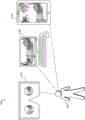
For purposes of illustration, FIG. 7 shows a plurality of exemplary frame sequences 702 (e.g., frame sequences 702-1 through 702-8) of frames of surface data representing color and depth data, respectively, of a surface of virtual object 304 visible from vantage points 306-1 through 306-8. For example, the first surface data frame in each frame sequence 702 (i.e., the uncovered surface data frames such that different views of the object 304 are visible in fig. 7) may correspond to the surface data frame 210 illustrated in fig. 6. Thus, the frame sequences 702-1 through 702-8 may be associated with the 3D rendering engines 204-1 through 204-8, respectively, and thus the virtual vantage points 306-1 through 306-8. For example, the frame sequence 702-1 may represent both the color and depth of virtual objects included within the virtual 3D space 302 as viewed from the virtual vantage point 306-1 during a particular time sequence 704 (e.g., a particular actual time period, a particular virtual timeline associated with an immersive virtual reality world, etc.). Similarly, the frame sequence 702-2 may represent the color and depth of virtual objects included within the virtual 3D space 302 when viewed from the virtual vantage point 306-2 during the time sequence 704, and so on for the frame sequences 702-3 through 702-8.
As described and illustrated above, each of the surface data frames generated by the 3D rendering engine 204 and included in the frame sequence 702 may be transmitted or otherwise communicated into the video data encapsulation system 212, which may be communicatively coupled to the 3D rendering engine 204. Based on each of the different frame sequences 702 of the surface data frames, the video data encapsulation system 212 may generate one or more transport streams to transmit the color video data stream and the depth video data stream for each virtual vantage point 306. For example, the video data encapsulation system 212 may generate a single transport stream containing the individual color video data streams and the depth video data streams associated with each frame sequence 702 (i.e., associated with each 3D rendering engine 204 and virtual vantage point 306), or the video data encapsulation system 212 may generate different transport streams of the color video data streams and the depth video data streams associated with each frame sequence 702.
Once generated, the video data encapsulation system 212 can provide the transport stream for streaming to a client-side media player device associated with the user. For example, the video data encapsulation system 212 may stream (e.g., via a network) a transport stream to the media player device itself, or may include a transport stream in a data pipe where it is further processed by another system and transmitted to the media player device (e.g., after processing and/or encapsulation by other devices, processes, and/or systems associated with the pipe).
As described above, in some examples, the system 100 and/or other systems (e.g., other server-side systems) and the apparatus described herein for rendering frames of a virtual scene from different vantages based on virtual entity description frames may be used to generate virtual reality media content to be experienced by a user. For example, in addition to the operations described above, a virtual reality media content provider system (e.g., system 100, video data packaging system 212, and/or other devices and systems described herein may be included within, or otherwise associated with, the virtual reality media content provider system) may further generate and provide virtual reality media content based on the transport stream generated and provided by video data packaging system 212. The virtual reality media content may represent a virtual scene and may be presented to a user for experiencing with respect to the virtual scene from dynamically selectable virtual vantage points corresponding to arbitrary virtual locations. For example, the dynamically selectable virtual vantage point may be selected by a user of the media player device while the user is experiencing the virtual scene using the media player device. Further, virtual reality media content may be provided to the media player device (e.g., by including the system 100 or a virtual reality media content provider system otherwise associated with the system 100) to allow a user to experience the virtual scene from dynamically selectable virtual vantages corresponding to arbitrary virtual locations within the virtual scene.
To illustrate, fig. 8 shows an exemplary configuration 800 in which an exemplary virtual reality media content provider system 802 ("provider system 802") comprising the system 100 and the video data packaging system 212 generates virtual reality media content that is provided to an exemplary client-side media player device 806 ("media player device 806") using a network 804 with which a user 808 experiences a virtual scene.
After the one or more transport streams have been generated based on the frame sequence 702 described above, the provider system 802 may further encode, encapsulate, encrypt, or otherwise process the one or more transport streams to form virtual reality media content, which the media player device 806 may be configured to render. For example, as will be described below, the virtual reality media content may include or represent multiple 2D video data streams (e.g., for each virtual vantage point 306, 2D video data streams associated with color data and depth data) that may be rendered by the media player device 806 to present a view of the virtual scene 300 from any arbitrary virtual vantage point within the virtual scene 300 (e.g., including virtual vantage points other than the virtual vantage point 306 that may be of interest to the user 808). Additionally or alternatively, the virtual reality media content may include data representing one or more volumetric models (e.g., 3D or 4D models) of virtual objects included within the virtual scene 300 that may also be rendered to be viewable from arbitrary virtual vantages. The virtual reality media content may then be distributed over the network 804 to one or more media player devices, such as media player device 806 associated with a user 808. For example, the provider system 802 may provide virtual reality media content to the media player device 806 such that the user 808 may experience the virtual scene 300 using the media player device 806.
In some examples, it may not be desirable for the user 808 to be limited to one or more discrete locations within the immersive virtual reality world represented by the virtual reality media content (e.g., representing the virtual scene 300). Thus, the provider system 802 may provide sufficient data within the virtual reality media content representing the virtual scene 300 to allow the virtual scene 300 to be rendered not only from the virtual vantage point 306, but from any dynamically selectable virtual vantage point corresponding to any virtual location within the virtual scene 300 (e.g., within or around the virtual 3D space 302). For example, the dynamically selectable virtual vantage point may be selected by the user 808 while the user 808 experiences the virtual scene 300 using the media player device 806.
As used herein, "arbitrary virtual location" may refer to any virtual point that is spatially associated with a virtual scene (e.g., within or around a virtual 3D space of the virtual scene). For example, any virtual location is not limited to a fixed location around the virtual scene (e.g., a fixed location associated with the virtual vantage point 306), but also includes all locations between the location associated with the virtual vantage point 306 and locations inside the virtual 3D space 302. Further, any virtual location may be associated with any virtual vantage point and is not limited to being aligned with any of the virtual vantage points 306. In some examples, such arbitrary virtual positions may correspond to the most desirable virtual vantage points within the virtual scene 300. For example, if the virtual scene 300 includes a basketball game, the user 808 may dynamically select a virtual vantage point in any arbitrary virtual location on the basketball court from which the game is experienced. For example, a user may dynamically select their virtual vantage point to follow a basketball up and down on a basketball court and experience a basketball game as if standing on the basketball court in the game. In other words, for example, although the virtual vantage point 306 may be located at a fixed location around the basketball court, the user 808 may dynamically select any virtual vantage point associated with any arbitrary location on the basketball court from which the game is experienced.
The network 804 may include a provider-specific wired or wireless network (e.g., a cable or satellite carrier network, or a mobile telephone network), the internet, a wide area network, a content delivery network, or any other suitable network. As may serve particular embodiments, data may flow between provider system 802 and media player device 806 (as well as other media player devices not explicitly shown) using any communication techniques, devices, media, and protocols.
The user 808 can use the media player device 806 to access and experience virtual reality media content received from the provider system 802. For example, the media player device 806 may be configured to generate (e.g., based on a color video data stream and a depth video data stream for each virtual vantage point included within a transport stream, which may be a 2D video data stream) a 3D representation of the virtual 3D space 302 of the virtual scene 300 to be experienced by the user 808 from any virtual vantage point (e.g., a dynamically selectable virtual vantage point selected by the user and corresponding to any virtual location within the virtual 3D space 302). To this end, the media player device 806 may include or be implemented by any device capable of presenting a field of view of an immersive virtual reality world (e.g., an immersive virtual reality world representing the virtual scene 300) and detecting user input from the user 808 while the user 808 experiences the immersive virtual reality world to dynamically update the immersive virtual reality world presented within the field of view.
For example, fig. 9 illustrates various exemplary types of media player devices 806 that may be used by a user 808 to experience virtual reality media content. In particular, as shown, the media player device 806 may take one of several different form factors, such as a head mounted virtual reality device 902 (e.g., a virtual reality gaming device) including a head mounted display screen, a personal computer device 904 (e.g., a desktop computer, a laptop computer, etc.), a mobile or wireless device 906 (e.g., a smart phone, a tablet computer device, etc., that may be mounted to the head of the user 808, possibly by way of a head mounted device), or by any other device or device configuration that may serve a particular implementation to facilitate receiving and/or presenting virtual reality media content. Different types of media player devices (e.g., head mounted virtual reality devices, personal computer devices, mobile devices, etc.) may provide different types of virtual reality experiences with different degrees of immersion for the user 808.
Fig. 10 illustrates an example virtual reality experience 1000 in which an example virtual reality media content representing a virtual scene as experienced from dynamically selectable virtual vantage points corresponding to an example arbitrary virtual position relative to the virtual scene is presented to a user 808. In particular, the virtual reality media content 1002 is presented within a field of view 1004 that shows a virtual scene from virtual vantages corresponding to any virtual location directly below a basketball standard within a virtual 3D space of the virtual scene that is being shot, the virtual scene-based immersive virtual reality world 1006 is available for a viewer to experience by providing user input (e.g., head movement, keyboard input, etc.) to view around and/or move around (i.e., dynamically select a virtual vantage point experienced therefrom) the immersive virtual reality world 1006.
For example, the field of view 1004 may provide a window through which the user 808 can easily and naturally view the immersive virtual reality world 1006 around. The field of view 1004 may be presented by the media player device 806 (e.g., on a display screen of the media player device 806) and may include video depicting objects surrounding the user within the immersive virtual reality world 1006. Additionally, as the user 808 experiences the immersive virtual reality world 1006, the field of view 1004 may dynamically change in response to user input provided by the user 808. For example, the media player device 806 may detect a user input (e.g., moving or steering a display screen on which the field of view 1004 is presented). In response, the field of view 1004 may display different objects and/or objects seen from different virtual vantage points or virtual positions, rather than objects seen from previous virtual vantage points or virtual positions.
In fig. 10, the immersive virtual reality world 1006 is illustrated as a hemisphere, indicating that the user 808 may view in any direction substantially forward, rearward, leftward, rightward, and/or upward within the immersive virtual reality world 1006 from a virtual vantage point at a location below the basketball standard that the user 808 has currently selected. In other examples, the immersive virtual reality world 1006 may include a full 360 ° by 180 ° sphere such that the user 808 may also look down. Additionally, the user 808 may move around to other locations within the immersive virtual reality world 1006 (i.e., dynamically selecting different dynamically selectable virtual vantage points within the virtual 3D space). For example, the user 808 may select a virtual vantage point at half a court, a virtual vantage point from a penalty line facing a basketball standard, a virtual vantage point hovering above a basketball standard, and so forth.
Fig. 11 illustrates an exemplary method 1100 for rendering frames of a virtual scene from different vantage points based on virtual entity description frames of the virtual scene. Although fig. 11 illustrates exemplary operations according to one embodiment, other embodiments may omit, add to, reorder, and/or modify any of the operations shown in fig. 11. One or more of the operations shown in fig. 11 may be performed by system 100 and/or by any implementation thereof.
In operation 1102, a virtual scene capture system may maintain data representing a plurality of virtual entities included within a virtual 3D space of a virtual scene. The plurality of virtual entities may include a virtual object and a plurality of virtual vantage points into the virtual 3D space. Specifically, for example, the plurality of virtual vantages may include a first virtual vantage point and a second virtual vantage point different from the first virtual vantage point. Operation 1102 may be performed by any of the means described herein.
In operation 1104, the virtual scene capture system may generate a virtual entity description frame representing a state of at least one of the plurality of virtual entities at a particular point in the time series. For example, the virtual scene capture system may generate a virtual entity description frame based on maintained data representing a plurality of virtual entities. Operation 1104 may be performed by any of the means described herein.
In operation 1106, the virtual scene capture system may provide the virtual entity description frames generated in operation 1104 to a plurality of server-side 3D rendering engines associated with the content provider system. For example, the virtual scene capture system may provide the virtual entity description frame to a first 3D rendering engine associated with a first virtual vantage point and configured to render a first surface data frame based on the virtual entity description frame, the first surface data frame representing color and depth data of a surface of a virtual object visible from the first virtual vantage point at a particular point in the temporal sequence. Furthermore, the virtual scene capture system may provide the virtual entity description frame to a second 3D rendering engine associated with a second virtual vantage point and configured to render a second surface data frame based on the virtual entity description frame, the second surface data frame representing color and depth data of a surface of a virtual object visible from the second virtual vantage point at a particular point in the temporal sequence. Operation 1106 may be performed by any of the means described herein.
In certain embodiments, one or more of the systems, components, and/or processes described herein may be implemented and/or performed by one or more suitably configured computing devices. To this end, one or more of the above-described systems and/or components may include or be implemented by any computer hardware and/or computer-implemented instructions (e.g., software) embodied on or by at least one non-transitory computer-readable medium configured to perform one or more of the processes described herein. In particular, the system components may be implemented on one physical computing device, or may be implemented on more than one physical computing device. Thus, the system components may include any number of computing devices, and may employ any of a number of computer operating systems.
In certain embodiments, one or more of the processes described herein may be implemented, at least in part, as instructions embodied in a non-transitory computer-readable medium and executable by one or more computing devices. In general, a processor (e.g., a microprocessor) receives instructions from a non-transitory computer-readable medium (e.g., a memory, etc.) and executes those instructions, thereby performing one or more processes, including one or more of the processes described herein. Such instructions may be stored and/or transmitted using any of a variety of known computer-readable media.
A computer-readable medium (also referred to as a processor-readable medium) includes any non-transitory medium that participates in providing data (e.g., instructions) that may be read by a computer (e.g., by a processor of a computer). Such a medium may take many forms, including but not limited to, non-volatile media and/or volatile media. For example, non-volatile media may include optical or magnetic disks and other persistent memory. For example, volatile media may include dynamic random access memory ("DRAM"), which typically constitutes a main memory. Common forms of computer-readable media include, for example, a magnetic disk, hard disk, magnetic tape, any other magnetic medium, a compact disc-read only memory ("CD-ROM"), a digital video disc ("DVD"), any other optical medium, a random access memory ("RAM"), a programmable read only memory ("PROM"), an electrically erasable programmable read only memory ("EPROM"), a FLASH-EEPROM, any other memory chip or cartridge, or any other tangible medium from which a computer can read.
Fig. 12 illustrates an exemplary computing device 1200 that may be specifically configured to perform one or more of the processes described herein. As shown in fig. 12, computing device 1200 may include a communications interface 1202, a processor 1204, a storage 1206, and an input/output ("I/O") module 1208 communicatively connected through a communications infrastructure 1210. Although an exemplary computing device 1200 is shown in fig. 12, the components illustrated in fig. 12 are not intended to be limiting. Additional or alternative components may be used in other embodiments. The components of the computing device 1200 shown in fig. 12 will now be described in more detail.
The communication interface 1202 may be configured to communicate with one or more computing devices. Examples of communication interface 1202 include, but are not limited to, a wired network interface (e.g., a network interface card), a wireless network interface (e.g., a wireless network interface card), a modem, an audio/video connection, and any other suitable interface.
Processor 1204 generally represents any type or form of processing unit (e.g., a central processing unit and/or a graphics processing unit) capable of processing data or interpreting, executing, and/or directing the execution of one or more of the instructions, processes, and/or operations described herein. The processor 1204 may direct the performance of operations according to one or more applications 1212, or other computer-executable instructions or another computer-readable medium, which may be stored in the storage 1206, for example.
Storage 1206 may include one or more data storage media, devices, or configurations and may take any type, form, and combination of data storage media and/or devices. For example, storage 1206 may include, but is not limited to, a hard disk drive, a network drive, a flash drive, a magnetic disk, an optical disk, RAM, dynamic RAM, other non-volatile and/or volatile data storage units, or a combination or sub-combination thereof. Electronic data, including data described herein, may be temporarily and/or permanently stored in storage 1206. For example, data representing one or more executable applications 1212 configured to direct the processor 1204 to perform any of the operations described herein may be stored within the storage 1206. In some examples, the data may be arranged in one or more databases residing within storage 1206.
The I/O module 1208 may include one or more I/O modules configured to receive user input and provide user output. One or more I/O modules may be used to receive input for a single virtual reality experience. The I/O module 1208 may include any hardware, firmware, or combination thereof that supports input and output capabilities. For example, I/O module 1208 may include hardware and/or software for capturing user input, including but not limited to a keyboard or keypad, a touch screen component (e.g., a touch screen display), a receiver (e.g., an RF or infrared receiver), a motion sensor, and/or one or more input buttons.
The I/O module 1208 may include one or more means for presenting output to a user, including but not limited to a graphics engine, a display (e.g., a display screen), one or more output drivers (e.g., a display driver), one or more audio speakers, and one or more audio drivers. In some embodiments, I/O module 1208 is configured to provide the graphical data to a display for presentation to a user. As may serve particular embodiments, the graphical data may represent one or more graphical user interfaces and/or any other graphical content.
In some examples, any of the facilities described herein may be implemented by or within one or more components of computing device 1200. For example, one or more applications 1212 residing within storage 1206 may be configured to direct processor 1204 to perform one or more operations or functions associated with virtual entity state tracking facility 102 or virtual entity description frame facility 104 of system 100 (see fig. 1). Likewise, storage facilities 106 of system 100 may be implemented by storage 1206 or within storage 1206.
To the extent that the above-described embodiments collect, store, and/or employ personal information provided by individuals, it should be understood that such information should be applicable in accordance with all applicable laws related to protecting personal information. In addition, the collection, storage, and use of such information may require an individual's consent for such activity, for example, through well-known "opt-in" or "opt-out" procedures that may be applicable to the circumstances and types of information. The storage and use of personal information may reflect the type of information in a suitably secure manner, for example, through various encryption and anonymization techniques for particularly sensitive information.
In the preceding description, various exemplary embodiments have been described with reference to the accompanying drawings. It will, however, be evident that various modifications and changes may be made thereto, and additional embodiments may be implemented, without departing from the scope of the invention as set forth in the appended claims. For example, certain features of one embodiment described herein may be combined with or substituted for features of another embodiment described herein. The specification and drawings are, accordingly, to be regarded in an illustrative rather than a restrictive sense.