CN110662506A - Tension Control in Actuation of Combined Instruments - Google Patents
Tension Control in Actuation of Combined Instruments Download PDFInfo
- Publication number
- CN110662506A CN110662506A CN201880032233.6A CN201880032233A CN110662506A CN 110662506 A CN110662506 A CN 110662506A CN 201880032233 A CN201880032233 A CN 201880032233A CN 110662506 A CN110662506 A CN 110662506A
- Authority
- CN
- China
- Prior art keywords
- tension
- tensions
- actuators
- joint
- instrument
- Prior art date
- Legal status (The legal status is an assumption and is not a legal conclusion. Google has not performed a legal analysis and makes no representation as to the accuracy of the status listed.)
- Granted
Links
Images


Classifications
-
- A—HUMAN NECESSITIES
- A61—MEDICAL OR VETERINARY SCIENCE; HYGIENE
- A61B—DIAGNOSIS; SURGERY; IDENTIFICATION
- A61B34/00—Computer-aided surgery; Manipulators or robots specially adapted for use in surgery
- A61B34/70—Manipulators specially adapted for use in surgery
- A61B34/71—Manipulators operated by drive cable mechanisms
-
- A—HUMAN NECESSITIES
- A61—MEDICAL OR VETERINARY SCIENCE; HYGIENE
- A61B—DIAGNOSIS; SURGERY; IDENTIFICATION
- A61B34/00—Computer-aided surgery; Manipulators or robots specially adapted for use in surgery
- A61B34/30—Surgical robots
- A61B34/35—Surgical robots for telesurgery
-
- A—HUMAN NECESSITIES
- A61—MEDICAL OR VETERINARY SCIENCE; HYGIENE
- A61B—DIAGNOSIS; SURGERY; IDENTIFICATION
- A61B17/00—Surgical instruments, devices or methods
- A61B2017/00017—Electrical control of surgical instruments
-
- A—HUMAN NECESSITIES
- A61—MEDICAL OR VETERINARY SCIENCE; HYGIENE
- A61B—DIAGNOSIS; SURGERY; IDENTIFICATION
- A61B17/00—Surgical instruments, devices or methods
- A61B17/00234—Surgical instruments, devices or methods for minimally invasive surgery
- A61B2017/00292—Surgical instruments, devices or methods for minimally invasive surgery mounted on or guided by flexible, e.g. catheter-like, means
- A61B2017/003—Steerable
- A61B2017/00305—Constructional details of the flexible means
- A61B2017/00314—Separate linked members
-
- A—HUMAN NECESSITIES
- A61—MEDICAL OR VETERINARY SCIENCE; HYGIENE
- A61B—DIAGNOSIS; SURGERY; IDENTIFICATION
- A61B17/00—Surgical instruments, devices or methods
- A61B17/00234—Surgical instruments, devices or methods for minimally invasive surgery
- A61B2017/00292—Surgical instruments, devices or methods for minimally invasive surgery mounted on or guided by flexible, e.g. catheter-like, means
- A61B2017/003—Steerable
- A61B2017/00318—Steering mechanisms
- A61B2017/00323—Cables or rods
- A61B2017/00327—Cables or rods with actuating members moving in opposite directions
-
- A—HUMAN NECESSITIES
- A61—MEDICAL OR VETERINARY SCIENCE; HYGIENE
- A61B—DIAGNOSIS; SURGERY; IDENTIFICATION
- A61B17/00—Surgical instruments, devices or methods
- A61B2017/00367—Details of actuation of instruments, e.g. relations between pushing buttons, or the like, and activation of the tool, working tip, or the like
- A61B2017/00398—Details of actuation of instruments, e.g. relations between pushing buttons, or the like, and activation of the tool, working tip, or the like using powered actuators, e.g. stepper motors, solenoids
-
- A—HUMAN NECESSITIES
- A61—MEDICAL OR VETERINARY SCIENCE; HYGIENE
- A61B—DIAGNOSIS; SURGERY; IDENTIFICATION
- A61B34/00—Computer-aided surgery; Manipulators or robots specially adapted for use in surgery
- A61B34/20—Surgical navigation systems; Devices for tracking or guiding surgical instruments, e.g. for frameless stereotaxis
- A61B2034/2046—Tracking techniques
- A61B2034/2061—Tracking techniques using shape-sensors, e.g. fiber shape sensors with Bragg gratings
-
- A—HUMAN NECESSITIES
- A61—MEDICAL OR VETERINARY SCIENCE; HYGIENE
- A61B—DIAGNOSIS; SURGERY; IDENTIFICATION
- A61B34/00—Computer-aided surgery; Manipulators or robots specially adapted for use in surgery
- A61B34/30—Surgical robots
- A61B2034/305—Details of wrist mechanisms at distal ends of robotic arms
- A61B2034/306—Wrists with multiple vertebrae
-
- A—HUMAN NECESSITIES
- A61—MEDICAL OR VETERINARY SCIENCE; HYGIENE
- A61B—DIAGNOSIS; SURGERY; IDENTIFICATION
- A61B34/00—Computer-aided surgery; Manipulators or robots specially adapted for use in surgery
- A61B34/70—Manipulators specially adapted for use in surgery
- A61B34/71—Manipulators operated by drive cable mechanisms
- A61B2034/715—Cable tensioning mechanisms for removing slack
-
- A—HUMAN NECESSITIES
- A61—MEDICAL OR VETERINARY SCIENCE; HYGIENE
- A61B—DIAGNOSIS; SURGERY; IDENTIFICATION
- A61B90/00—Instruments, implements or accessories specially adapted for surgery or diagnosis and not covered by any of the groups A61B1/00 - A61B50/00, e.g. for luxation treatment or for protecting wound edges
- A61B90/06—Measuring instruments not otherwise provided for
- A61B2090/064—Measuring instruments not otherwise provided for for measuring force, pressure or mechanical tension
- A61B2090/066—Measuring instruments not otherwise provided for for measuring force, pressure or mechanical tension for measuring torque
Landscapes
- Health & Medical Sciences (AREA)
- Surgery (AREA)
- Engineering & Computer Science (AREA)
- Life Sciences & Earth Sciences (AREA)
- Biomedical Technology (AREA)
- Robotics (AREA)
- Nuclear Medicine, Radiotherapy & Molecular Imaging (AREA)
- Heart & Thoracic Surgery (AREA)
- Medical Informatics (AREA)
- Molecular Biology (AREA)
- Animal Behavior & Ethology (AREA)
- General Health & Medical Sciences (AREA)
- Public Health (AREA)
- Veterinary Medicine (AREA)
- Manipulator (AREA)
Abstract
Description
相关申请的交叉参考CROSS-REFERENCE TO RELATED APPLICATIONS
本申请要求2017年11月10日提交的美国临时专利申请号62/584,608的优先权,其全部内容通过引用合并于此。This application claims priority to US Provisional Patent Application No. 62/584,608, filed November 10, 2017, the entire contents of which are incorporated herein by reference.
背景技术Background technique
机器人程序通常采用借助于计算机或通过计算机接口进行控制的器械,这些器械可能包括一个或多个可铰接的部分(例如关节),并通过使用张力承载元件进行控制。Robotic programs typically employ instruments controlled by means of a computer or through a computer interface, which may include one or more articulable parts (eg, joints), and are controlled through the use of tension-bearing elements.
发明内容SUMMARY OF THE INVENTION
在一方面,一种医疗器械系统包括致动器、医疗器械以及可操作地连接到致动器的控制系统。该医疗器械包括末端部分和传动系统,其中每个传动系统将末端部分耦合到多个致动器中的一个致动器,使得致动器可操作以驱动传动系统移动末端部分。该控制系统被配置为执行操作,这些操作包括确定末端部分的当前配置与末端部分的期望配置之间的差异,以及基于该差异并基于恒定偏移张力来操作致动器以将张力施加到传动系统。恒定偏移张力独立于由传动系统承受的当前张力。In one aspect, a medical device system includes an actuator, a medical device, and a control system operably connected to the actuator. The medical device includes a tip portion and a drive train, wherein each drive train couples the tip portion to one of a plurality of actuators such that the actuator is operable to drive the drive train to move the tip portion. The control system is configured to perform operations including determining a difference between a current configuration of the tip portion and a desired configuration of the tip portion, and operating an actuator to apply tension to the transmission based on the difference and based on a constant offset tension system. The constant offset tension is independent of the current tension experienced by the drivetrain.
在另一方面,一种操作器械的方法包括确定器械的末端部分的当前配置与期望配置之间的差异,以及操作致动器以将张力施加到传动系统。传动系统被耦合以移动末端部分。张力基于差值和恒定偏移张力。恒定偏移张力独立于由传动系统承受的当前张力。In another aspect, a method of operating an instrument includes determining a difference between a current configuration and a desired configuration of a distal portion of the instrument, and operating an actuator to apply tension to a transmission system. A drivetrain is coupled to move the end portion. Tension is based on differential and constant offset tension. The constant offset tension is independent of the current tension experienced by the drivetrain.
在另一方面,一种器械系统包括致动器、器械以及可操作地连接至致动器的控制系统。该器械包括末端部分和传动系统,每个传动系统将末端部分耦合到这些致动器中的一个致动器,使得致动器可操作以驱动传动系统移动末端部分。控制系统被配置为执行操作,这些操作包括确定末端部分的当前配置与末端部分的期望配置之间的差异,并基于该差异确定施加到传动系统的张力。这些张力中的一个张力保持在最大张力,并且其余张力不大于最大张力。In another aspect, an instrument system includes an actuator, an instrument, and a control system operably connected to the actuator. The instrument includes a tip portion and a transmission system, each drive system coupling the tip portion to one of the actuators, such that the actuator is operable to drive the drive system to move the tip portion. The control system is configured to perform operations including determining a difference between a current configuration of the end portion and a desired configuration of the end portion, and determining a tension applied to the driveline based on the difference. One of these tensions is kept at the maximum tension, and the remaining tensions are not greater than the maximum tension.
在另一方面,描述了存储可由处理装置执行的指令的一个或多个非暂时性计算机可读介质。在执行指令后,处理装置执行操作,这些操作包括确定器械的末端部分的当前配置与器械的末端部分的期望配置之间的差异,基于该差异确定要应用于传动系统的第一张力,以及操作致动器以向传动系统施加第二张力。第二张力基于第一张力和恒定偏移张力。恒定偏移张力独立于由传动系统承受的当前张力。In another aspect, one or more non-transitory computer-readable media storing instructions executable by a processing device are described. After execution of the instructions, the processing device performs operations including determining a difference between the current configuration of the distal end portion of the instrument and a desired configuration of the distal end portion of the instrument, determining a first tension to apply to the transmission system based on the difference, and operating an actuator to apply a second tension force to the driveline. The second tension is based on the first tension and the constant offset tension. The constant offset tension is independent of the current tension experienced by the drivetrain.
前述的优点可以包括以下和本文其他地方所描述的那些内容。The foregoing advantages may include those described below and elsewhere herein.
根据本发明的一个方面,用于具有多个自由度的器械的控制系统和方法使用器械的当前配置/速度与器械的期望配置/速度之间的差异来确定和控制近侧致动器通过一组传动系统施加到器械的力。即使器械的传动系统在近侧致动器和远程致动元件之间具有不可忽略的依从性,使用所施加的力和指示医疗器械的最终配置的反馈也允许医疗器械的机器人控制。反馈方法尤其允许精确的器械操作,即使当无法从近侧致动器的位置直接推断出器械的配置时也是如此。According to one aspect of the present invention, a control system and method for an instrument with multiple degrees of freedom uses the difference between the instrument's current configuration/velocity and the instrument's desired configuration/velocity to determine and control the proximal actuator via a The force applied to the instrument by the group drive system. The use of applied force and feedback indicative of the final configuration of the medical instrument allows robotic control of the medical instrument even if the instrument's drive train has non-negligible compliance between the proximal and remote actuating elements. The feedback method especially allows precise instrument manipulation even when the configuration of the instrument cannot be directly inferred from the position of the proximal actuator.
在本发明的一个实施例中,测量或以其他方式确定末端执行器或尖端的配置,并且将尖端的当前配置与期望配置之间的差异用于确定所要求的关节扭矩和实现所期望的尖端配置所需的施加力。此控制方法的实施例可以允许选择尖端的动态行为,例如用以促进器械与组织的相互作用,同时允许器械的其他部分的灵活性。In one embodiment of the invention, the configuration of the end effector or tip is measured or otherwise determined, and the difference between the current configuration of the tip and the desired configuration is used to determine the required joint torque and achieve the desired tip Configure the desired applied force. Embodiments of this control method may allow the dynamic behavior of the tip to be selected, eg, to facilitate interaction of the instrument with tissue, while allowing flexibility in other parts of the instrument.
在本发明的另一个实施例中,对器械中每个关节的配置进行测量,并且当前关节配置与期望关节配置之间的差异被用于确定将所有关节移动到期望配置所需的致动器力。In another embodiment of the invention, the configuration of each joint in the instrument is measured and the difference between the current joint configuration and the desired joint configuration is used to determine the actuators required to move all joints to the desired configuration force.
本发明的一个特定实施例是一种医疗系统,其包括多个关节、致动器和传动系统。传动系统具有分别耦合到致动器的近端,并且每个传动系统具有附接到关节中的相关联的一个关节的远端,以允许传递相关联关节的铰接力。医疗系统中的传感器生成测量值,该测量值指示关节或器械尖端的配置,并且控制系统操作致动器以将力施加到传动系统,从传感器接收配置测量值,并使用配置测量值来确定施加到传动系统的致动力。One particular embodiment of the present invention is a medical system that includes a plurality of joints, actuators, and transmission systems. The transmission systems have proximal ends respectively coupled to the actuators, and each transmission system has a distal end attached to an associated one of the joints to allow the transfer of articulation forces of the associated joint. Sensors in the medical system generate measurements that indicate the configuration of the joint or the tip of the instrument, and the control system operates the actuators to apply a force to the driveline, receives the configuration measurements from the sensors, and uses the configuration measurements to determine the application Actuation force to the drivetrain.
尽管本文描述的一些示例经常涉及医疗程序和医疗器械,但是所公开的技术也适用于非医疗程序和非医疗器械。例如,本文描述的器械、系统和方法可以用于非医疗目的,包括工业用途、通用机器人用途、非组织工件的操纵和/或美容改进。其他非手术应用包括在从人或动物解剖结构去除的组织上使用(不返回人或动物解剖结构)或在人或动物尸体上使用。Although some of the examples described herein often refer to medical procedures and medical devices, the disclosed techniques are also applicable to non-medical procedures and non-medical devices. For example, the devices, systems, and methods described herein can be used for non-medical purposes, including industrial use, general robotic use, manipulation of non-tissue workpieces, and/or cosmetic improvement. Other non-surgical applications include use on tissue removed from human or animal anatomy (without returning human or animal anatomy) or on human or animal cadavers.
附图说明Description of drawings
图1示出了机器人控制的医疗器械的特征。Figure 1 shows the features of a robotically controlled medical device.
图2示出了可以使用根据本发明的实施例的控制过程来操作的医疗器械,该控制过程控制通过顺应性(compliant)传动系统施加的力以控制器械的铰接椎骨。2 illustrates a medical instrument that may be operated using a control process that controls the force applied through a compliant transmission system to control the articulating vertebrae of the instrument according to an embodiment of the present invention.
图3A示出了医疗器械,其中根据本发明的实施例的控制过程可以通过具有最小和最大力传递的传动系统进行操作以操作机械关节。Figure 3A shows a medical device in which a control process according to an embodiment of the present invention may operate through a transmission system with minimum and maximum force transmission to operate a mechanical joint.
图3B示出了本发明的实施例,其中关节包括连续柔性结构。Figure 3B shows an embodiment of the present invention in which the joint comprises a continuous flexible structure.
图3C示出了用于控制图3B的关节中的单个运动自由度的一对筋束(tendon)的位置。Figure 3C shows the position of a pair of tendons used to control a single degree of freedom of movement in the joint of Figure 3B.
图4示意性地示出了机器人医疗系统,并且特别地示出了在本发明的实施例中使用的量(quantity),这些量控制通过顺应性传动系统连接至致动器的远程关节。Figure 4 schematically shows a robotic medical system and in particular the quantities used in embodiments of the present invention that control remote joints connected to actuators by compliant transmission systems.
图5A是根据本发明的实施例的控制过程的流程图。5A is a flowchart of a control process according to an embodiment of the present invention.
图5B是用于确定与致动器速度和关节速度之间的差异相关联的张力校正的过程的流程图。5B is a flowchart of a process for determining a tension correction associated with a difference between actuator speed and joint speed.
图5C是用于确定与操纵同一关节的致动器的速度之间的差异相关联的张力校正的过程的流程图。5C is a flowchart of a process for determining tension corrections associated with differences between the speeds of actuators manipulating the same joint.
图5D示出了用于控制最大和最小施加张力的功能。Figure 5D shows the function for controlling the maximum and minimum applied tension.
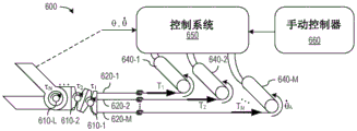
图6示意性地示出了机器人医疗系统,并且特别示出了在本发明的实施例中使用的控制多关节器械的量。Figure 6 schematically shows a robotic medical system, and in particular the amount of control multi-joint instrument used in an embodiment of the present invention.
图7A是根据本发明的实施例的一个过程的流程图,该过程基于测量的关节构造和期望的关节构造之间的差异来选择施加的张力。7A is a flowchart of a process for selecting applied tension based on a difference between a measured joint configuration and a desired joint configuration, according to an embodiment of the present invention.
图7B是根据本发明的实施例的一个过程的流程图,该过程基于测量的尖端配置和期望的尖端配置之间的差异来选择施加的张力。7B is a flowchart of a process for selecting applied tension based on a difference between a measured tip configuration and a desired tip configuration, according to an embodiment of the present invention.
图8A是根据本发明的实施例的可使用驱动力控制来操作以控制具有平行致动轴线的关节的多关节器械的一部分的侧视图。8A is a side view of a portion of a multi-joint instrument operable using drive force control to control joints having parallel axes of actuation, according to an embodiment of the present invention.
图8B和图8C分别示出了具有根据本发明的实施例的可使用驱动力控制来操作的具有垂直致动轴线的关节的多关节器械的一部分的侧视图和端视图。8B and 8C show, respectively, side and end views of a portion of a multi-joint instrument having a joint with a vertical actuation axis operable using drive force control in accordance with an embodiment of the present invention.
图9A示出了本发明的实施例,其中关节包括提供两个运动自由度的连续柔性结构。Figure 9A shows an embodiment of the present invention in which the joint includes a continuous flexible structure that provides two degrees of freedom of movement.
图9B和图9C示出了分别采用四个和三个筋束来控制图9A的关节中的两个运动自由度的本发明的实施例。Figures 9B and 9C illustrate embodiments of the present invention employing four and three tendons, respectively, to control two degrees of freedom of motion in the joint of Figure 9A.
图9D示出了两关节医疗器械的实施例,其中每个关节包括连续柔性结构并且提供两个运动自由度。Figure 9D shows an embodiment of a two-joint medical device where each joint includes a continuous flexible structure and provides two degrees of freedom of movement.
图9E示出了本发明的实施例,其采用六个筋束来控制由图9D的器械中的两个关节提供的四个运动自由度。Figure 9E shows an embodiment of the present invention employing six tendons to control the four degrees of freedom of motion provided by the two joints in the apparatus of Figure 9D.
图10示意性地示出了机器人医疗系统,并且特别地示出了在本发明的另一实施例中使用的控制多关节器械的量。Figure 10 schematically shows a robotic medical system, and in particular the amount of control multi-joint instrument used in another embodiment of the present invention.
图11是示出根据本发明的实施例的一个过程的流程图,该过程通过对多关节器械中的关节进行顺序评估来确定张力。11 is a flowchart illustrating a process for determining tension through sequential evaluation of joints in a multi-joint instrument, according to an embodiment of the present invention.
图12A是根据一些实施例的医疗器械系统的简化图。12A is a simplified diagram of a medical device system in accordance with some embodiments.
图12B是根据一些实施例的具有扩展医疗工具的医疗器械的简化图。12B is a simplified diagram of a medical device with extended medical tools in accordance with some embodiments.
具体实施方式Detailed ways
根据本发明的一个方面,可以经由由致动器驱动的传动系统来控制医疗器械,以重新定位医疗器械的关节,从而移动医疗器械的末端部分。人类系统操作者(例如,外科医生)可以指示医疗器械的当前期望配置和/或当前期望速度,而器械的实际配置/速度可以例如通过传感器的测量来确定或估计。在一些情况下,实际配置和/或实际速度可以使用传感器来测量,该传感器生成指示实际配置和/或实际速度的测量值。然后可以根据期望配置和测量配置来选择力、张力或扭矩,并通过传动系统来施加以使器械朝其期望配置移动。如果事先选择的施加的力、张力或扭矩导致关节过冲(overshooting)或无法到达期望位置,则可以更改施加的力、张力或扭矩的选择标准。According to one aspect of the invention, the medical instrument can be controlled via a transmission system driven by an actuator to reposition the joints of the medical instrument to move the distal portion of the medical instrument. A human system operator (eg, a surgeon) may indicate the current desired configuration and/or current desired velocity of the medical instrument, while the actual configuration/velocity of the instrument may be determined or estimated, for example, by sensor measurements. In some cases, actual configuration and/or actual speed may be measured using sensors that generate measurements indicative of actual configuration and/or actual speed. The force, tension or torque can then be selected according to the desired and measured configurations and applied through the drive system to move the instrument toward its desired configuration. The selection criteria for the applied force, tension or torque can be changed if the pre-selected applied force, tension or torque causes the joint to overshoot or fail to reach the desired position.
例如,图1示出了机器人控制的器械100,其具有简化的结构以示出一些机器人操作的器械的基本工作原理。(如本文中所用,术语“机器人”或“机器人方式”等包括涉及远程操作或非远程操作的方面。)器械100在细长轴或主管120的远端处包括工具或末端执行器110。在所示的示例中,末端执行器110是诸如钳子或剪刀的钳口工具,其具有分开的钳口112和114,并且至少钳口112可移动以相对于钳口114打开或关闭。在医疗过程期间使用中,主管120的远端上的末端执行器110可以通过患者的小切口插入并定位在患者体内的工作部位处。然后,例如在执行外科手术任务期间,随后可以打开和关闭钳夹112,并且因此必须精确地控制钳口112以仅执行期望的运动。器械100的一些实施方式除了打开和关闭钳口112和114以帮助执行过程之外,还具有许多移动自由度。For example, FIG. 1 shows a robotically controlled instrument 100 having a simplified structure to illustrate the basic working principles of some robotically operated instruments. (As used herein, the terms "robot" or "robotics" and the like include aspects involving teleoperation or non-teleoperation.) Instrument 100 includes a tool or end effector 110 at the distal end of elongated shaft or main tube 120 . In the example shown, end effector 110 is a jaw tool, such as pliers or scissors, having separate jaws 112 and 114 , and at least jaw 112 is movable to open or close relative to jaw 114 . In use during a medical procedure, the end effector 110 on the distal end of the main tube 120 can be inserted through a small incision in the patient and positioned at the work site in the patient. The jaws 112 can then be opened and closed subsequently, such as during the performance of a surgical task, and therefore the jaws 112 must be precisely controlled to perform only the desired motion. Some embodiments of the instrument 100 have many degrees of freedom of movement in addition to opening and closing the jaws 112 and 114 to aid in the procedure.
主管120的近端附接到有时被称为后端机构130的传动或驱动机构130。筋束122和124从后端机构130穿过主管120延伸并附接到末端执行器110。筋束(例如,筋束122、124)可以包括多股线缆、杆、金属带、管或此类结构的组合。The proximal end of the main tube 120 is attached to a transmission or drive mechanism 130 sometimes referred to as the rear end mechanism 130 . The tendons 122 and 124 extend from the rear end mechanism 130 through the main tube 120 and are attached to the end effector 110 . The tendons (eg, tendons 122, 124) may comprise stranded cables, rods, metal tapes, tubes, or a combination of such structures.
一些器械(包括诸如外科器械之类的医疗器械)包括将后端机构130连接到末端执行器110的其他致动构件的附加筋束(图1中未示出)、腕机构(未示出)或主管120中的致动椎骨;此类架构后端机构130可以操纵筋束以操作末端执行器110和/或器械100的其他致动元件。Some instruments (including medical instruments such as surgical instruments) include additional tendons (not shown in FIG. 1 ) that connect the back end mechanism 130 to other actuation members of the end effector 110 , a wrist mechanism (not shown) Or an actuating vertebra in the main tube 120 ; such an architectural back end mechanism 130 can manipulate tendons to operate the end effector 110 and/or other actuation elements of the instrument 100 .
图1示出了钳口112具有销关节结构116,该销关节结构116为钳口112的移动提供了单个自由度。两个筋束122和124附接到钳口112以及后端机构130中的滑轮132,从而滑轮132的旋转促使钳口112旋转。FIG. 1 shows that the jaws 112 have a pin joint structure 116 that provides a single degree of freedom for movement of the jaws 112 . The two tendons 122 and 124 are attached to the jaw 112 and the pulley 132 in the rear end mechanism 130 such that rotation of the pulley 132 causes the jaw 112 to rotate.
滑轮132附接到驱动马达140,驱动马达140可以在机械臂(未示出)的末端处,并且控制系统150电控制驱动马达140。在一些实施方式中,器械100包括控制系统150的一部分或全部。在一些实施方式中,控制系统150与器械100部分或完全分离。在一些实施方式中,控制系统150包括计算系统以及合适的软件、固件和外围硬件。除了其他功能外,在一些实施方式中,控制系统150还向用户(例如,系统操作者、医务人员或外科医生(如果是医疗系统的话))提供工作部位和末端执行器110的图像,并提供外科医生可操作以控制末端执行器110的移动的控制装置或操纵器。可以以单视、立体等方式提供工作部位的图像。The pulley 132 is attached to a drive motor 140, which may be at the end of a robotic arm (not shown), and the control system 150 controls the drive motor 140 electrically. In some embodiments, instrument 100 includes a portion or all of control system 150 . In some embodiments, the control system 150 is partially or completely separate from the instrument 100 . In some embodiments, the control system 150 includes a computing system and suitable software, firmware and peripheral hardware. Among other functions, in some embodiments, the control system 150 provides images of the work site and end effector 110 to a user (eg, a system operator, medical personnel, or surgeon (if a medical system)) and provides A control device or manipulator operable by the surgeon to control the movement of the end effector 110 . Images of the work site can be provided in monovision, stereo, etc.
解释控制装置的用户操纵以及生成引起钳口112c的相应移动的马达信号所需的软件或固件可能是复杂的,并且在实际的机器人医疗器械中通常是复杂的。为了考虑控制任务的一部分,用于驱动马达140的控制信号的生成通常采用钳口112的角度或位置与后端机构130中的驱动马达140或滑轮132的角度或位置之间的关系。如果筋束122和124是刚性的(例如,如果筋束的拉伸可忽略不计),则控制系统150可使用如由器械100的几何形状所定义的驱动马达140的角位置与钳口112的角位置之间的直接关系,以用于在外科医生指示时确定移动钳口112所需的控制信号。例如,在工作负荷下,筋束122和124的较小拉伸可以通过将马达位置与执行器位置相关联的一些数学模型来处理。然而,如果包括末端部分致动器110、筋束122和124以及后端机构130的机械结构具有较高程度的顺应性,则马达140(或滑轮132)的角位置与钳口112的角位置之间的关系可能难以为医疗器械建立足够准确的模型。The software or firmware required to interpret the user manipulation of the controls and generate the motor signals that cause the corresponding movement of the jaws 112c can be complex, and is often complex in practical robotic medical instruments. To account for part of the control task, the generation of control signals for drive motor 140 typically employs a relationship between the angle or position of jaw 112 and the angle or position of drive motor 140 or pulley 132 in rear end mechanism 130 . If tendons 122 and 124 are rigid (eg, if tendon stretching is negligible), control system 150 may use the angular position of drive motor 140 and the position of jaw 112 as defined by the geometry of instrument 100 A direct relationship between the angular positions for use in determining the control signals needed to move the jaws 112 when directed by the surgeon. For example, under working load, the minor stretching of tendons 122 and 124 can be handled by some mathematical model that correlates motor position to actuator position. However, if the mechanical structure including end portion actuator 110 , tendons 122 and 124 , and rear end mechanism 130 has a higher degree of compliance, then the angular position of motor 140 (or pulley 132 ) is the same as the angular position of jaw 112 The relationship can be difficult to model with sufficient accuracy for medical devices.
应当注意,在下文中,医疗器械的关节可以是销关节结构或向器械尖端提供一个或多个运动自由度的结构。例如,关节可以是连续柔性节段,也可以是近似于连续柔性节段的销关节的组合,也可以是不纯粹回转的而是提供一些滚动关节的单个旋转关节。参见例如Cooper等人的标题为“Flexible Wrist for Surgical Tool”的美国专利号7,320,700以及Cooper等人的标题为“Surgical Tool Having a Positively Positionable Tendon-Actuated Multi-disk Wrist Joint”的美国专利号6,817,974。It should be noted that in the following, the joint of the medical device may be a pin joint structure or a structure that provides one or more degrees of freedom of movement to the tip of the device. For example, the joint can be a continuous flexible segment, a combination of pin joints that approximate a continuous flexible segment, or a single rotational joint that is not purely rotational but provides some rolling joints. See, eg, US Patent No. 7,320,700 to Cooper et al., entitled "Flexible Wrist for Surgical Tool," and US Patent No. 6,817,974 to Cooper et al., entitled "Surgical Tool Having a Positively Positionable Tendon-Actuated Multi-disk Wrist Joint."
还应该注意的是,可以对致动器位置进行伺服控制,以产生期望的器械尖端运动或位置。只要致动器和器械关节之间的传动系统对于所有实际目的都是刚性的,这种方法就可能是有效的。参见例如标题为“Camera Referenced Control in a MinimallyInvasive Surgical Apparatus”的美国专利6,424,885。如果传动系统的灵活性可以被精确地建模并且可以是控制器中包括的模型,则这种方法也可以是有效的,如在Barbagli等人的标题为“Robotic Instrument Control System”的美国专利申请公布号2009/0012533A1中所描述。It should also be noted that the actuator position can be servo controlled to produce the desired instrument tip movement or position. This approach may be effective as long as the transmission system between the actuator and the instrument joint is rigid for all practical purposes. See, eg, US Patent 6,424,885 entitled "Camera Referenced Control in a Minimally Invasive Surgical Apparatus". This approach can also be effective if the flexibility of the drivetrain can be accurately modeled and can be included in the controller, as described in the US patent application titled "Robotic Instrument Control System" by Barbagli et al. Described in Publication No. 2009/0012533A1.
尽管本文描述的一些示例经常涉及医疗程序和医疗器械,但是所公开的技术也适用于非医疗程序和非医疗器械。例如,本文描述的器械、系统和方法可以用于非医疗目的,包括工业用途、通用机器人用途、非组织(tissue)工件的操纵和/或美容改进。其他非手术应用包括在从人或动物解剖结构去除的组织上使用(不返回人或动物解剖结构)或在人或动物尸体上使用。Although some of the examples described herein often refer to medical procedures and medical devices, the disclosed techniques are also applicable to non-medical procedures and non-medical devices. For example, the devices, systems, and methods described herein may be used for non-medical purposes, including industrial use, general robotic use, manipulation of non-tissue workpieces, and/or cosmetic improvement. Other non-surgical applications include use on tissue removed from human or animal anatomy (without returning human or animal anatomy) or on human or animal cadavers.
图2示出了可被实现为顺应性医疗器械的器械200的一部分。器械200具有传动系统。除了本文描述的传动系统的示例之外,传动系统的示例在标题为“Compliant SurgicalDevice”的美国专利号12/494,797中被进一步描述,其全部内容通过引用并入本文。器械200包括通过控制筋束222和224中的相应张力来操纵的接合元件210。通常,器械200可以包含类似于接合元件210的许多机械关节,并且每个关节都可以使用类似于筋束222和224的筋束来控制。在示例性实施例中,器械200是进入引导件(entry guide),其可以被操纵以跟随患者体内的自然管腔。进入引导件通常会包括柔软的外部护套(未示出),该护套围绕椎骨(包括元件210)并提供一个或多个中心管腔,其他医疗器械可通过该中心管腔插入以便进入工作部位。特别期望进入引导件中有顺应性以防止进入引导件的作用或反作用伤害可能移动或压向进入引导件的周围组织。然而,其他类型的医疗器械也可以从图2所示类型的顺应性驱动机构中受益。FIG. 2 shows a portion of a device 200 that may be implemented as a compliant medical device. The instrument 200 has a transmission system. In addition to the examples of powertrains described herein, examples of powertrains are further described in US Patent No. 12/494,797, entitled "Compliant Surgical Device," the entire contents of which are incorporated herein by reference. Instrument 200 includes engagement element 210 that is manipulated by controlling respective tensions in tendons 222 and 224 . In general, instrument 200 may contain a number of mechanical joints similar to engagement element 210 , and each joint may be controlled using tendons similar to tendons 222 and 224 . In an exemplary embodiment, instrument 200 is an entry guide that can be manipulated to follow a natural lumen in a patient. The access guide will typically include a flexible outer sheath (not shown) that surrounds the vertebrae (including element 210) and provides one or more central lumens through which other medical instruments may be inserted for access to work part. It is particularly desirable to have compliance in the access guide to prevent action or reaction injuries of the access guide that may move or press against surrounding tissue of the access guide. However, other types of medical devices may also benefit from a compliant drive mechanism of the type shown in FIG. 2 .
器械200包括后端机构230,该后端机构包括一个或多个传动系统,该传动系统将末端部分(例如接合元件210)连接到一个或多个致动器。例如,筋束222和224提供了顺应性传动系统,该顺应性传动系统连接到接合元件210以驱动马达242和244。具体地,后端机构230包括附接到筋束222和224以及驱动马达242和244的弹簧系统235。图2中的每个弹簧系统235包括机械驱动系统232和恒力弹簧234。每个驱动系统232耦合马达242或244并将驱动马达242或244的旋转运动转换为线性运动,这改变了由相关联的恒力弹簧234施加到筋束222或224的恒定力。在所示实施例中,每个恒力弹簧234包括常规的胡克定律弹簧236和凸轮238。每个弹簧236连接到相关联的驱动系统232,从而驱动系统232的线性运动移动弹簧236的近端。每个凸轮238具有第一引导表面和第二引导表面,附接到相关联的弹簧236的远端的线缆237附接并搁置在第一引导表面上,筋束222或224的一部分附接并搁置在第二引导表面上。每个凸轮238的引导表面通常提供不同的力矩臂,以用于所附接的线缆237和所附接的筋束222或224的动作,并且被成形为使得当拉伸或牵引一段长度的筋束220或224而改变由附接的弹簧236施加的力时,筋束222或224中的张力保持恒定。每个凸轮238的每个表面可以是延伸用于一次或多次回转的螺旋表面,便提供筋束222和224的期望运动范围,同时在筋束222或224中保持恒定的张力。Instrument 200 includes a rear end mechanism 230 that includes one or more drive trains that connect a tip portion (eg, engagement element 210 ) to one or more actuators. For example, tendons 222 and 224 provide a compliant drivetrain connected to engagement element 210 to drive motors 242 and 244 . Specifically, rear end mechanism 230 includes a spring system 235 attached to tendons 222 and 224 and drive motors 242 and 244 . Each spring system 235 in FIG. 2 includes a mechanical drive system 232 and a constant force spring 234 . Each drive system 232 couples a motor 242 or 244 and converts rotational motion of the drive motor 242 or 244 to linear motion, which alters the constant force applied to the tendons 222 or 224 by the associated constant force spring 234 . In the illustrated embodiment, each constant force spring 234 includes a conventional Hooke's law spring 236 and a cam 238 . Each spring 236 is connected to an associated drive system 232 such that linear motion of the drive system 232 moves the proximal end of the spring 236 . Each cam 238 has a first guide surface on which a cable 237 attached to the distal end of the associated spring 236 is attached and a second guide surface on which a portion of the tendon 222 or 224 is attached and rest on the second guide surface. The guide surface of each cam 238 typically provides a different moment arm for the action of the attached cable 237 and attached tendon 222 or 224, and is shaped such that when a length of The tension in the tendon 222 or 224 remains constant as the force applied by the attached spring 236 is changed by the tendon 220 or 224. Each surface of each cam 238 may be a helical surface extending for one or more revolutions, providing the desired range of motion of the tendons 222 and 224 while maintaining a constant tension in the tendons 222 or 224 .
每个驱动系统232控制对应弹簧236的近端的位置,从而影响对应弹簧236中的基线拉伸量以及所附接的筋束222或224中的张力。在操作中,如果弹簧系统235中的驱动系统232拉动附接的弹簧236,则弹簧236开始拉伸,并且如果附接到弹簧系统235的元件210和筋束222或224保持固定,则弹簧236施加到凸轮238的力增加,因此附接的筋束222或224中的张力增加。筋束222和224各自可以包括线缆或线缆的一部分。因此,筋束222和224中的张力线性地依赖于(根据胡克定律,凸轮238的力矩臂和弹簧236的弹簧常数)相应弹簧236的近端的移动,但每个弹簧系统235的行为是不对称的。例如,每个弹簧系统235响应于使筋束222或224移动的外部力或远侧力而以恒定的力起作用。恒力弹簧234和驱动系统232可以可替代地以各种方式来实现,诸如在美国专利申请号12/494,797中进一步描述的那些方式。Each drive system 232 controls the position of the proximal end of the corresponding spring 236, thereby affecting the amount of baseline stretch in the corresponding spring 236 and the tension in the attached tendons 222 or 224. In operation, if the drive system 232 in the spring system 235 pulls the attached spring 236, the spring 236 begins to stretch, and if the element 210 and the tendons 222 or 224 attached to the spring system 235 remain stationary, the spring 236 The force applied to the cam 238 increases and thus the tension in the attached tendon 222 or 224 increases. The tendons 222 and 224 may each comprise a cable or a portion of a cable. Thus, the tension in tendons 222 and 224 is linearly dependent (according to Hooke's law, the moment arm of cam 238 and the spring constant of spring 236) the movement of the proximal end of the respective spring 236, but the behavior of each spring system 235 is asymmetrical. For example, each spring system 235 acts with a constant force in response to an external or distal force that moves tendon 222 or 224. Constant force spring 234 and drive system 232 may alternatively be implemented in various ways, such as those further described in US Patent Application No. 12/494,797.
接合元件210具有单个运动自由度(例如,绕轴线的旋转),并且通常在驱动马达242或244旋转驱动系统232以改变由附接的恒力弹簧234施加的力时进行移动。控制系统250可以使用传感器260来测量元件210的取向。下面进一步描述的控制过程使用此类测量值来计算操纵接合元件210所需的施加力或驱动马达242或244操纵接合元件210的施加扭矩。Engagement element 210 has a single degree of freedom of movement (eg, rotation about an axis) and typically moves when drive motor 242 or 244 rotates drive system 232 to vary the force applied by attached constant force spring 234 . Control system 250 may use sensor 260 to measure the orientation of element 210 . The control process described further below uses such measurements to calculate the applied force required to operate the engagement element 210 or the applied torque of the drive motor 242 or 244 to operate the engagement element 210 .
在一些情况下,驱动机构可以是顺应性的,使得外力可以在没有驱动系统232的对应旋转的情况下移动元件210。结果,接合元件210的位置或取向与驱动系统232或驱动马达242的位置之间的关系可以是不固定的。传感器260可以是例如形状传感器,其可以沿着包括元件210的器械200的长度来感测接合元件210的形状。形状传感器的一些示例在Larkin等人的(2007年5月20日提交的)标题为“Robotic Surgery System Including PositionSensors Using Fiber Bragg Gratings”的美国专利申请公布号US 2007/0156019 A1以及Giuseppe M.Prisco的(2008年6月30日提交的)标题为“Fiber Optical Shape sensor”的美国专利申请号12/164,829中描述,这两个专利的全部内容通过引用并入本文。在一些实施方式中,可以可替代地使用能够测量关节元件210的角位置的任何传感器。例如,在一些情况下,传感器可以对应于与器械200的驱动机构(例如,驱动系统232、驱动马达242或驱动马达244)相关联的传感器。传感器可以包括编码器、转速计或其他合适的传感器以测量机构的位置或速度。基于接合元件210的位置和速度与驱动机构的位置和速度之间的运动学关系,测量的位置或测量的速度可以用于确定接合元件210的位置和速度。In some cases, the drive mechanism may be compliant such that an external force may move element 210 without corresponding rotation of drive system 232 . As a result, the relationship between the position or orientation of engagement element 210 and the position of drive system 232 or drive motor 242 may not be fixed. Sensor 260 may be, for example, a shape sensor that may sense the shape of engagement element 210 along the length of instrument 200 including element 210 . Some examples of shape sensors are found in US Patent Application Publication No. US 2007/0156019 Al by Larkin et al. (filed May 20, 2007) entitled "Robotic Surgery System Including PositionSensors Using Fiber Bragg Gratings" and by Giuseppe M. Prisco Described in US Patent Application No. 12/164,829 (filed June 30, 2008) entitled "Fiber Optical Shape sensor," the entire contents of which are incorporated herein by reference. In some embodiments, any sensor capable of measuring the angular position of the joint element 210 may alternatively be used. For example, in some cases, the sensors may correspond to sensors associated with a drive mechanism (eg, drive system 232 , drive motor 242 , or drive motor 244 ) of instrument 200 . Sensors may include encoders, tachometers, or other suitable sensors to measure the position or speed of the mechanism. Based on the kinematic relationship between the position and velocity of the engagement element 210 and the position and velocity of the drive mechanism, the measured position or measured velocity can be used to determine the position and velocity of the engagement element 210 .
当将后端机构230从马达组件包上拆下时,器械200具有“向后驱动”能力,弹簧系统235仍使筋束222和224不松弛,并且允许手动布置(或摆放)器械的远侧部分而不会损坏后端机构230或在筋束222或224中产生松弛。这种“向后驱动”能力通常是外科手术器械的期望性质,尤其是具有柔性主管的器械,在器械未受到控制系统250的主动控制时,该柔性主管在器械插入期间可能会弯曲或被操纵。例如,可以手动摆放器械200,并且主轴内的筋束不会受到不适当的拉力或松弛。When the rear end mechanism 230 is removed from the motor assembly package, the instrument 200 has a "back drive" capability, the spring system 235 still keeps the tendons 222 and 224 from slack, and allows for manual placement (or positioning) of the instrument's remote side portion without damaging the rear end mechanism 230 or creating slack in the tendons 222 or 224. This "backward drive" capability is often a desirable property of surgical instruments, especially instruments with flexible main tubes that may bend or be manipulated during instrument insertion when the instrument is not actively controlled by the control system 250 . For example, the instrument 200 can be placed manually without undue tension or relaxation of the tendons within the main shaft.
在图3A中示出了用于医疗器械中的关节的顺应性传动系统的另一示例。图3A示出了医疗器械300的示例性实施例,该医疗器械使用致动过程,该致动过程允许驱动马达在器械操作期间相对于驱动马达自由滑行或驱动筋束相对于驱动马达滑动,如标题为“PassivePreload and Capstan Drive for Surgical Instruments”的美国专利申请号12/286,644所述,其全部内容通过引用并入本文。医疗器械300的末端部分可以被操纵。例如,末端部分可以对应于可通过医疗器械300的致动过程控制的末端执行器、尖端或其他设备中的一个。在图3A所示的示例中,医疗器械300具有在主管320的末端处的末端执行器310,并且后端机构330操纵穿过主管320的筋束322和324,以控制末端执行器310的运动自由度。在所示的实施例中,筋束322和324附接到末端执行器310中的机械构件,使得筋束322和324中的张力趋向于使末端执行器310围绕枢轴关节结构在相反方向上旋转。Another example of a compliant transmission system for a joint in a medical device is shown in Figure 3A. FIG. 3A shows an exemplary embodiment of a medical device 300 that uses an actuation process that allows a drive motor to freely slide relative to the drive motor or to slide the drive tendons relative to the drive motor during operation of the device, such as Described in US Patent Application No. 12/286,644, entitled "PassivePreload and Capstan Drive for Surgical Instruments," the entire contents of which are incorporated herein by reference. The distal portion of the medical device 300 can be manipulated. For example, the tip portion may correspond to one of an end effector, tip, or other device that is controllable by the actuation process of the medical device 300 . In the example shown in FIG. 3A , medical device 300 has
图3A中的器械300的末端部分的关节结构仅是示例,并且在本发明的可替代实施例中可以采用用于器械的末端部分的其他关节机构,其响应于施加到一对筋束的张力而提供单个运动自由度。例如,图3B示出了一个实施例,其中末端执行器310包括:诸如在导管、胃肠道内窥镜、结肠和支气管中常见的关节;引导线;或其他内窥镜器械,诸如用于组织取样的抓取器和针头。The articulation of the distal portion of the instrument 300 in Figure 3A is merely an example, and other articulation mechanisms for the distal portion of the instrument that respond to tension applied to a pair of tendons may be employed in alternative embodiments of the present invention Rather, it provides a single degree of freedom of movement. For example, FIG. 3B shows an embodiment in which
主管320可以包括能够响应于通过筋束322和324施加的力而挠曲或弯曲的导管。导管关节可以简单地包括塑性材料的挤出件,该塑性材料的挤出件响应于筋束322和324中的张力差异而弯曲。在一种配置中,如图3C所示,筋束322和324延伸穿过导管内的管腔并附接到导管的末端。相应地,筋束322和324中的力可以用于使导管在对应于具有更大张力的筋束322或324的方向上弯曲。例如,可以在插入期间使用导管的弯曲来操纵导管。在一些示例中,远侧传感器360可以测量导管远侧部分的弯曲角度以测量或计算“关节”角度和速度。在一个特定实施例中,弯曲角度可以定义为导管相对于导管的远侧柔性部分的基部的尖端取向。除了所测量的关节角度和速度可以通过乘以致动器线缆管腔和远侧柔性部分的中心之间的距离而转换为筋束的位置和速度之外,图3B的末端执行器310的导管关节的后端和控制架构可以与图3A的实施例的后端和控制架构相同。Main tube 320 may include a conduit capable of flexing or bending in response to forces applied through
附接到主管320的近端的后端机构330用作传动,其将由驱动马达342和344施加的扭矩转换成相应筋束322和324中的张力以及施加到末端执行器310中的致动关节的力或扭矩。在所示的实施例中,驱动马达342和344可以是直接耦合到绞盘332和334的直接驱动电马达,相应的筋束322和324缠绕在绞盘332和334周围。特别地,筋束322以设定的包角(其可以小于完整的一圈或大至一个或多个圈)在对应的绞盘332周围缠绕,并且其一端不附连到绞盘332,而是从绞盘332延伸到被动预加载系统333。类似地,筋束324以一组包角围绕对应的绞盘334缠绕,并且具有从绞盘334延伸到被动预加载系统335的末端。由于不需要将筋束322和324永久地附接到绞盘332和334,筋束322和324能够相对于绞盘332和334并且相对于分别耦合到绞盘332和334的驱动马达342和344的轴滑动。The rear end mechanism 330 attached to the proximal end of the main tube 320 serves as a transmission that converts the torque applied by the drive motors 342 and 344 into tension in the
筋束322和324的近端附接到相应的被动预加载系统333和335,每个被动预加载系统在图3A中被实现为凸轮和弹簧,其共同作用为恒力弹簧。该弹簧可以是通常可用胡克定律建模的弹簧。被动预加载系统333和335受到偏置,使得绞盘332和334在器械300的整个运动范围内对筋束322和324施加非零的力或张力。借助于该配置,当绞盘332和334自由旋转时,被动预加载系统333和335控制筋束322和324中的张力,并通过拉入或放出所需长度的筋束322和324来避免筋束322和324松弛。当后端机构330脱离马达342和344时,被动预加载系统333和335仍然防止筋束322和324松弛,并且允许末端执行器310和主管320(当柔性时)被手动布置(或摆放)而不会损坏后端机构330或在筋束322或324中产生松弛。因此,器械300还具有类似于以上针对图2的器械200所描述的“反向驱动”能力。The proximal ends of
末端执行器310可以在控制系统350的主动控制和人工输入(例如,主从伺服控制系统中的主控制输入)的控制下使用驱动马达342和344进行操作。例如,当马达342拉动筋束322时,马达扭矩作为在筋束322的远侧部分中施加的张力被传递。(绞盘332可以施加到筋束322的近侧部分的最大张力取决于筋束322开始相对于领导332滑动的张力,但通常,可以选择实际使用的最大张力以防止筋束322和324在绞盘332和334上滑动。)同时,当关闭马达344的电源时,允许马达344和绞盘334靠惯性滑动,筋束324可以被保持在其最小张力,该最小张力是被动预加载系统335通过绞盘334施加到筋束324的近端的恒定力。然后,筋束322中的较大张力趋向于导致末端执行器310在图3A中逆时针旋转。类似地,关闭马达342的电源并向马达344供电以通过筋束324向末端致动器310施加力趋向于使末端部分致动器310在图3A中顺时针旋转。当筋束322和324受到张力并且在绞盘332和334上接受筋束322和324的滑动时马达342和344靠惯性滑动的能力不允许控制系统350依赖马达340和末端执行器310的角位置之间的固定关系。然而,控制系统350可以使用传感器360来测量末端执行器310相对于通过筋束322和324致动的关节的角位置。
图2、图3A和图3B的器械可以在致动器和被致动的关节之间具有传动系统,这提供了合乎需要的顺应性,特别是对于具有柔性主管的器械而言。具有顺应性的传动系统也可出现在更传统的器械中。例如,图1的已知器械可以在弯曲的器械节段中使用护套或鲍登(Bowden)线缆,并且在直节段中使用杆件。杆件可以减小拉伸,该拉伸干扰致动器和关节位置的直接关系。在一些应用中可能期望使用更具柔性的材料的筋束(例如,其中需要电绝缘或最小摩擦的聚合物筋束)。依赖于致动器和关节位置之间的直接关系,此类筋束可能在控制过程中引入不可接受的拉伸量。实心钢拉线也可以用于传动系统或用作传动系统。The instruments of FIGS. 2, 3A, and 3B may have a transmission system between the actuator and the actuated joint, which provides desirable compliance, especially for instruments with flexible main tubes. A compliant drivetrain can also be found in more traditional instruments. For example, the known instrument of Figure 1 may use sheaths or Bowden cables in curved instrument segments and rods in straight segments. The rod can reduce stretch that interferes with the direct relationship of the actuator and joint position. In some applications it may be desirable to use tendons of more flexible materials (eg, polymer tendons where electrical insulation or minimal friction is required). Depending on the direct relationship between actuator and joint position, such tendons may introduce unacceptable amounts of stretch during control. Solid steel cables can also be used in or used as drive trains.
根据本发明的一方面,用于图2、图3A和图3B的医疗器械或以其他方式具有顺应性传动系统的器械的控制过程可以采用机械关节的位置的远程测量值来确定要施加以驱动机械关节的张力。在另一方面,用于图2、图3A和图3B的医疗器械或以其他方式具有顺应性传动系统的器械的过程可以采用器械致动器的位置的测量值来确定要施加以驱动机械关节的张力。该控制过程也可以用于具有刚性传动系统的器械。该控制过程也可以用于具有刚性传动系统的器械。图4示意性地示出了具有机械关节410的医疗器械400的概括,该机械关节410具有与角度或位置θ对应的运动自由度。术语“位置”在本文中广泛地用于包括笛卡尔位置、角位置或机械系统的自由度的配置的其他指示。According to one aspect of the invention, a control process for the medical device of FIGS. 2, 3A, and 3B, or a device that otherwise has a compliant transmission system, may employ remote measurements of the position of the mechanical joint to determine what to apply to actuate Tension of mechanical joints. In another aspect, a process for the medical device of Figures 2, 3A, and 3B, or a device that otherwise has a compliant transmission system, may employ measurements of the position of the device's actuators to determine what to apply to drive a mechanical joint tension. This control process can also be used for instruments with rigid transmission systems. This control process can also be used for instruments with rigid transmission systems. Figure 4 schematically shows an overview of a
关节410通过传动系统420连接到致动器440,使得关节410远离致动器440,例如,关节410可以在器械400的远端处,而致动器440在器械400的近端处。就此而言,关节410形成器械400的末端部分的一部分。在所示的实施例中,传动系统420连接关节410,使得由致动器440施加到传动系统420的张力T趋向于使关节410沿顺时针方向旋转。通常,传动系统420包括用于将力从致动器440传递到关节410的整个机构,并且致动器440可以向传动系统420施加力或扭矩,这引起传动系统420的线缆或其他部件中的张力。此张力通常可以与施加的力或扭矩成比例,因此此处使用的术语“张力”不失一般性,也指示力或扭矩。The joint 410 is connected to the
传动系统420可以是(但不是必须)顺应性的,以至于关节410的位置与致动器440的位置之间的直接关系对于控制关节410而言将不够准确。就此而言,在一些示例中,传动系统420可以是顺应性的,但是直接关系足够准确以用于控制关节410。在一些情况下,传动系统420可以拉伸,使得在施加到传动系统420的张力T的最小值和最大值之间,传动系统420的有效长度上的差异可以对应于45°的关节活动度。相反,典型的医疗装置允许拉伸对应于不超过几个关节活动度,以便能够基于致动器位置准确地对关节位置进行建模。应该理解的是,在一般情况下,顺应性不限于弹簧结构的简单胡克定律拉伸。例如,在图2的实施例中,传动系统420可以包括筋束222和后端机构230的至少一部分,或者在图3A的实施例中,传动系统420可以包括筋束322和后端机构330的至少一部分。通常,传动系统420对施加于传动系统420的近端处的张力T以及施加于关节410或沿传动系统420的长度施加的外力的响应可能难以建模。The
传感器(未示出)测量远程关节410处的位置θ并将测量的位置θ提供给控制系统450。传感器可以另外测量关节410的移动的速度

可替代地或附加地,致动器440的位置可以足够准确以用于控制关节410。传感器可以包括与致动器440相关联的传感器,例如编码器、转速计或其他传感器以测量致动器440的位置或速度。Alternatively or additionally, the position of the
可以包括图2或图3A的驱动马达242或342的致动器440将张力T施加到传动系统420的近端,并且通过传动系统420将力或扭矩施加到关节410。在一些情况下,其他力和扭矩也可以被施加到关节410。例如,一个或多个其他传动系统420可以连接到关节410,并共同施加趋向于引起关节410旋转的净张力或力。在图4的所示实施例中,传动系统422连接到关节410和致动器442,因此传动系统422中的张力趋向于与施加的张力T相反,并在图4中逆时针旋转关节410。附加的传动系统422或连接到关节410的传动系统可以是除了传动系统422或多个传动系统连接到关节410的差异之外与传动系统420相同。
控制系统450可以是执行程序的通用计算机或者被接线以生成驱动信号的电路,该驱动信号控制致动器440施加到传动系统420的张力T。当致动器440是电动马达时,该驱动信号可以是控制从致动器440输出的扭矩的驱动电压或电流,并且张力T等于马达扭矩除以有效力矩臂,在该力矩臂处张力T被施加到传动系统420。如下面进一步所述,控制系统450可以使用关节410的期望位置θD、期望速度


在时间间隔Δt中将关节410从其当前位置θ移动到期望位置θD所需的张力T将通常取决于许多因素,包括:抵抗所施加张力T的关节410的有效惯性;施加张力T的致动器440或者耦合到关节410并施加净有效力的任何其他传动系统422的惯性;施加于关节410的外力;与关节410的致动或传动系统的移动相反的内部和外部摩擦力;关节410的当前速度
图5A是用于控制具有图4的器械400的基础结构的医疗器械的过程500的流程图。过程500通过确定关节410的位置θ的当前值并确定关节速度


在步骤510之后,步骤515随后获取关节410的期望位置θD和期望速度并且步骤520计算所测量的位置和期望位置之间的差异或误差(θD-θ)以及所测量的速度和期望速度之间的差异或误差
在步骤520中计算出的位置误差可以指示末端部分(例如,关节410)的当前配置与末端部分(例如,关节410)的期望配置之间的差异。可以使用位置误差和速度误差来确定关节410到达期望位置θD所需的张力T。本文描述的张力未必应用于传动系统。本文描述的张力可以指施加到传动系统420的张力或者被确定或检测并用于选择另一张力以施加到传动系统420的张力。在图5A的实施例中,施加的张力T可以包括多个贡献,并且主要贡献是远侧张力TDIST,它被确定为位置误差(θD-θ)和速度误差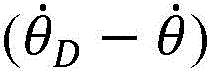
在一个特定实施例中,函数f1具有下面的方程1的形式,其中g1和g2是增益因子,C是常数或几何相关参数,并且Tsign是符号,即±1。符号Tsign与由传动系统420中的张力T产生的关节410的移动相关联,并且可以例如在传动系统420中的张力T倾向于增大位置坐标θ的情况下是正的(例如+1),并且可以是在传动系统420中的张力T倾向于减小位置坐标θ的情况下是负的(例如-1)。在另一实施例中,函数f1对力施加下限,例如以便使力总是正的并且足以避免传动系统中的松弛。参数C可以是根据由系统的其他部分施加到关节410的已知力或建模力选择的常数。例如,参数C可以是被选择以平衡由向关节410施加力的其他传动系统引起的扭矩的常数或者可以考虑预期摩擦或外力。然而,参数C并不需要严格是常数,而是可以包含非常数项,以补偿可以有效建模的诸如重力或机构刚度之类的性质,并且因此参数C可以取决于所确定的关节位置或速度。可以根据所期望的关节410的刚度和阻尼来选择增益因子g1和g2。特别是,当将关节410用作静态抓握器时,施加到组织的净抓握力或扭矩取决于方程1的项g1(θD-θ)。例如,在一些实施方式中,抓取器获得的力或扭矩取决于该项g1(θD-θ)和命令位置。一些实施方式还对可以实现的最大扭矩或力施加了限制。通常,可以根据关节410的期望的刚度和阻尼或响应性或者根据误差的累积来选择增益因子g1和g2以及常数C。例如,当插入器械400以跟随患者体内的自然管腔时,可以将增益因子g1设置为较低值,以使关节410表现得柔软并防止关节410伤害周围的组织。在插入后,可以将增益因子g1设置为较高的值,其允许外科医生用该器械执行精确的外科手术任务。In one particular embodiment, the function f1 has the form of Equation 1 below, where g1 and g2 are gain factors, C is a constant or geometrically related parameter, and Tsign is the sign , ie, ±1. The sign T sign is associated with the movement of the joint 410 produced by the tension T in the
方程1: Equation 1:
方程1的项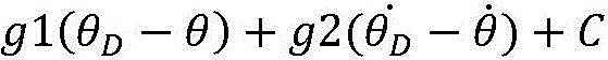
通过适当选择函数f1(例如,适当选择方程1中的参数g1、g2和C),远侧张力TDIST可以近似致动器440以响应于由手动控制器460的操作人员操纵的方式移动关节410所需施加的力。然而,在一些条件下,步骤530、535、540和550提供了可选的校正。特别地,可选步骤530和535分别计算了位置误差(θD-θ)的饱和总和(saturated sum)或饱和积分I并且算出积分张力TINT。积分张力TINT可以是正的、零或负的,可以被添加作为对在步骤525中计算出的远侧张力TDIST的校正。积分张力TINT被计算为饱和积分I的函数f2,并可以仅是积分I与增益因子的乘积。在步骤530中计算出的饱和积分I可以仅是过去N个位置误差间隔(θD-θ)的总和或者间隔末尾的测量位置与要达到的期望位置之间的差(θD,i-θD,i-1)。总和中包含的间隔数量N可以不受限制,并且积分I可能会饱和,因为不允许积分的量值超过最大饱和值。通常会选择饱和值来限制积分张力TINT的最大值或最小值。然而在计算函数f2的值时也可以可替代地限制积分张力TINT的最小值和最大值。By appropriate selection of function f 1 (eg, appropriate selection of parameters g 1 , g 2 , and C in Equation 1 ), distal tension T DIST can approximate the manner in which actuator 440 responds to manipulation by the operator of
可选步骤540计算在本文中被称为近侧张力TPROX的另一种校正,其可以是正的、零或负的。近侧张力TPROX可以被添加到在步骤525中计算的远侧张力TDIST。图5B是用于实施步骤540以计算近侧张力TPROX的示例过程的流程图。用于实施步骤540的该示例过程通过读取致动器440的速度


图5A的可选步骤550计算成对张力(pair tension)TPAIR,其可以是对在步骤525中计算出的远侧张力TDIST的正校正、零校正或负校正。图5C是用于实现步骤550以便计算成对张力TPAIR的示例过程的流程图。在步骤552中,通过读取致动器440的速度


在图5A的步骤560中,将张力T确定为远侧张力TDIST、近侧张力TPROX、成对张力TPAIR和积分张力TINT的总和的函数f3。在一些情况下,可以对张力T的最大值和最小值施加约束。例如,在图5D的实施例中,函数f3限制了张力T的最大值和最小值。最大张力TMAX和最小张力TMIN可以在控制系统450的编程中(例如,在软件中)设置。致动器440、442被可操作地连接到控制系统450,并且因此可以由控制系统450控制,使得张力T不超过最大张力TMAX,并且使得张力T不降到最小张力TMIN以下。可以设置最大张力TMAX以避免因较大的力而损坏器械,并且可以设置最小张力TMIN以抑制传动系统420和422中的筋束的松弛。这可以确保传动系统420和422中的筋束不会变得脱轨或纠缠。在一些情况下,最大张力TMAX和最小张力TMIN中的仅一个由控制系统450强制执行,而在其他情况下,两者都被强制执行。In
当器械400耦合到致动器440、442时,控制系统450可以启动最大张力TMAX、最小张力TMIN或最大张力TMAX和最小张力TMIN两者的强制执行。特别地,最大张力TMAX和最小张力TMIN可以在致动器440、442耦合到传动系统420、422时被强制执行。可以配置器械400,使得在传动系统420、422上没有任何外力的情况下传动系统420、422的筋束松弛。就此而言,当传动系统420、422的筋束从致动器440、442解耦时,筋束可以松弛。当传动系统420、422耦合到致动器440、442时,可能检测到传动系统420、422中的在最小张力TMIN以下的张力,从而使控制系统450强制执行最小张力TMIN并以使得张力T等于或大于最小张力TMIN的方式操作致动器440、442。可以施加张力T以强制执行最小张力TMIN并获得期望的位置θD和/或期望的速度
在一些情况下,通过在后端机构中采用适当的设计而不是在软件中进行设置,顺应性传动系统本身可能具有最小或最大张力。例如,图3A中所示的传动系统具有最小张力TMIN,该最小张力TMIN在马达/致动器342或344惯性滑行时由预加载系统333或335的设置控制,并且该传动系统具有当耦合马达342或344的扭矩超过筋束322或324在绞盘332或334上滑动时的点引起的滑动产生的最大张力TMAX。通常,它是In some cases, the compliant drivetrain itself may have a minimum or maximum tension by employing proper design in the rear end mechanism rather than setting it in software. For example, the drivetrain shown in FIG. 3A has a minimum tension TMIN controlled by the setting of the preload system 333 or 335 when the motor/actuator 342 or 344 is coasting, and the drivetrain has when The torque of the coupled motor 342 or 344 exceeds the maximum tension T MAX resulting from the sliding caused by the point at which the
图5A的步骤565生成使致动器440施加在步骤560中计算出的张力T的控制信号。例如,当致动器440是直接驱动电动马达时的控制信号可以是被控制成与计算出的张力T成比例的驱动电流。控制系统450在步骤570中使致动器440在一段时间间隔Δt内施加并保持计算出的张力T,在此期间,关节410朝当前期望位置θD移动。当改变张力T时,全张力T的施加将延迟一段时间,该时间取决于致动器440的惯性。优选地,致动器440的惯性相对较小以快速响应。例如,用作致动器440的驱动马达的惯性将优选小于关节410的惯性的五倍。在时间Δt之后,过程500分支回到步骤510,以重复测量关节位置,获取目标位置和速度以及计算要在下个时间间隔期间施加的张力T。通常,时间Δt应该足够小,以提供对器械操作者来说显得平滑的运动,并且该运动不会在器械中引起不希望的振动。例如,每秒250次或更多地计算和设置张力T,将提供对人眼看似平滑的移动,并且将提供响应于人类命令(例如,对控制器460的人工操纵)的器械操作。张力T的计算中的误差的使用通常会导致关节410收敛在期望位置上,无论是否计算积分张力TINT并且无需对器械或外部环境进行详细建模或测量。然而,如上所述,在计算施加的张力T中使用的参数(诸如增益g1和g2)可以针对特定器械进行调谐,并在使用中进行进一步调谐以补偿器械的外部环境的变化。Step 565 of FIG. 5A generates a control signal that causes the
还可以使用图5A的控制过程500来控制致动器442施加到传动系统422的张力,并且基于与致动器440和传动系统420相比时的致动器442和传动系统422的相似性和差异,在过程500中用于致动器442和传动系统422的参数可以与用于致动器440和传动系统420的参数可以相同或不同。特别地,在图4的配置中的致动器442的符号值Tsign将与致动器440的符号值Tsign相反,因为传动系统422和420在相反方向上连接到旋转关节410。因此,对于一个致动器440或442,在步骤525中计算的主要张力贡献TDIST通常为负。计算施加的张力T的步骤560可以将负张力总和TDIST+TPROX+TPAIR+TINT设置为如图5D所示的最小张力TMIN。因此,通常可以基于另一致动器将施加最小张力TMIN的假设来选择步骤525中的远侧张力TDIST的计算。The tension applied by the
上述用于控制医疗器械中的单个关节的原理也可以用于同时控制器械中的多个关节。图6示意性地示出了多关节医疗器械600以及在器械600的控制过程中使用的一些量。器械600包括L个关节610-1至610-L,在本文中统称为关节610。如下面进一步所述,每个关节610提供相邻机械构件的相对位置或取向的范围,并通常具有一个或两个运动自由度。器械600的关节610提供总共N个自由度,其中自由度的数量N大于或等于关节610的数量L,并且可以使用N分量或向量θ描述关节610的自由度的配置。N分量速度向量与向量θ相关联。使关节610-1至610-L移动的扭矩τ1至τN分别与向量θ的N分量相对应,因为扭矩τ1至τN趋向于引起向量θ的相应分量改变。The principles described above for controlling a single joint in a medical device can also be used to control multiple joints in a device simultaneously. FIG. 6 schematically illustrates a multi-joint medical device 600 and some quantities used in the control of the device 600 . Instrument 600 includes L joints 610-1 through 610-L, collectively referred to herein as
使用M个传动系统620-1至620-M(在本文中统称为传动系统620)和M个致动器640-1至640-M(在本文中统称为致动器640)致动关节610。传动系统620和致动器640可以与上面参考图4描述的传动系统420和致动器440类似或相同。通常,传动系统620和致动器640的数量M大于自由度的数量N,但是M和N之间的关系取决于具体的医疗器械和器械中的关节的力学。例如,可以使用两个传动系统620来致动提供单个运动自由度的关节610,并且可以使用三个或四个传动系统620来致动提供两个自由度的关节610。自由度和致动传动系统之间的其他关系是可能的。控制系统650操作致动器640-1至640-M以选择致动器640-1至640-M分别施加到传动系统620-1至620-M的相应张力T1至TM。
器械600的控制系统650可以使用代表位置向量θ和速度向量的一个或多个测量值,以确定位置向量θ和速度向量


控制系统650还确定关节610的期望配置。期望配置可以指示关节610的期望位置向量θD和速度向量


图7示出了根据本发明的一个实施例的用于控制诸如图6的器械600的多关节器械的控制过程700。过程700通过从一个或多个传感器(例如,与器械相关联或与致动器640耦合)确定关节位置向量θ而在步骤710中开始。例如,还可以使用关节移动的直接测量或通过计算两次之间的位置测量量的变化来确定速度向量 Figure 7 illustrates a
在一些示例中,致动器640的位置可以被认为机械地耦合到关节610的位置。在步骤710中,可以基于具有与致动器640的各个位置对应的元素的致动器位置向量θA来确定位置向量θ。使用方程2确定针对从1到N的索引i的每个位置分量θi,该方程2定义了方程组,该方程组定义了致动器位置和关节位置之间的关系。在方程2中,在铰接关节610的M个致动器640中,θ1至θN分别是关节610的位置向量θ的分量,并且θA1至θAM分别是位置向量θA的分量。针对索引I=1到N和索引J=1到M的每个系数bIJ通常对应于致动器J和关节I之间的耦合常数。例如,对于给定的I和给定的J,bIJ的单位耦合常数指示关节I的位置被视为与致动器J的位置成正比。具有分量bIJ的矩阵可以被称为耦合矩阵C。In some examples, the position of the
方程2: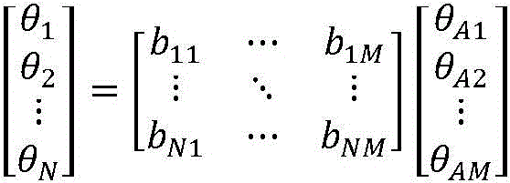
控制系统650在步骤715中接收外科医生的指令。外科医生的指令可以指示器械的期望配置,例如,指定器械的特定工作部分的位置和速度。例如,外科医生通过操纵手动控制660可以指示器械的远侧尖端或末端执行器的期望位置、速度、取向和旋转,诸如在标题为“Aspects of a Control System of a Minimally Invasive Surgical Apparatus”的美国专利号6,493,608中所述,其通过引用并入本文。The
然后,步骤720将来自手动控制器660的指令转换成关节610的期望位置向量θD和速度向量


还应该理解的是,当针对器械的期望命令求解逆运动学问题时,也可以在器械的关节之间强制实施软件强制约束,例如,可以强制将两个关节的关节位置和速度命令设为相同或相反或具有给定的比例,以有效地在关节之间实现虚拟凸轮机构。软件强制约束可以包括器械的传动系统中的软件强制最小张力、器械的传动系统中的最大张力等。可以在外科手术过程期间动态地强制实行软件强制约束。随着期望位置、期望速度、测量位置和测量速度变化,软件强制约束可以变化。It should also be understood that software-enforced constraints can also be enforced between the joints of the instrument when solving the inverse kinematics problem for the desired command of the instrument, for example, the joint position and velocity commands of the two joints can be forced to be the same. Or vice versa or with a given scale to effectively implement a virtual cam mechanism between the joints. Software-enforced constraints may include software-enforced minimum tension in the instrument's drive train, maximum tension in the instrument's drive train, and the like. Software-enforced constraints can be enforced dynamically during the surgical procedure. The software-enforced constraints can vary as the desired position, desired velocity, measured position, and measured velocity vary.
步骤725计算位置误差向量(θD-θ)和速度误差向量

方程3:
步骤735使用在步骤730中计算出的扭矩来确定远侧张力TDIST。远侧张力TDIST是与传动系统620-1至620-M和致动器640-1至640-M对应的M分量向量。远侧张力的确定取决于器械关节和传动系统之间的几何形状或力学原理。特别是在多个关节的情况下,每个关节不仅会受到附接到关节的传动系统直接施加的力的影响,还会受到连接到更接近器械远侧的关节的传动系统的影响。医疗器械中的扭矩和张力通常可以使用方程4形式的方程来建模。在方程4中,τ1至τN是扭矩向量的分量,而T1至TM分别是与关节610铰接的M个传动系统620中的远侧张力。针对索引I=1至N和索引J=1至M的每个系数aIJ通常对应于针对与扭矩τI对应的关节和旋转轴线的张力TJ的有效力矩臂。Step 735 uses the torque calculated in
方程4: Equation 4:
因此,步骤735中的计算对应于求解M个变量T1至TM的N个方程。由于M通常大于N,所以解不是唯一的,因此可以选择不等式约束,诸如所有张力均大于一组最小值的约束条件,并且最佳条件(诸如选择一组最低最大值的张力的条件)可以应用于提供具有期望特性(诸如在所有或所选关节中始终保持在期望阈值以上的最小张力)的唯一解。方程4的具有不等式和最优约束(诸如最小张力约束)的矩阵逆问题可以通过一些众所周知的技术来解决,诸如线性规划的SIMPLEX方法。(例如,参见“Linear Programming 1:Introduction”,GeorgeB.Dantzig和Mukund N.Thapa,Springer-Verlag,1997,通过引用将其全部内容并入本文。)根据本发明的另一方面,可以使用以下过程确定远侧张力:顺序评估从最远侧关节开始的关节,并基于几何参数和先前为更多远侧关节计算出的张力来求解连接到每个关节的传动系统中的张力。Thus, the calculation in
在一些情况下,要施加的远侧张力T1至TM与要由致动器640施加的致动器扭矩τA1至τAN成正比。就此而言,在一些情况下,在步骤735处,确定致动器扭矩τA1至τAN。在方程5(τA=Dτ)中,针对索引I=1至N和索引J=1至M的耦合矩阵D的每个系数dJI通常对应于关节I和致动器J之间的扭矩耦合。如果关节610的位置向量θ是基于方程2确定的,则可以基于耦合矩阵C确定要由致动器640施加的扭矩τ1至τN(由扭矩向量τ表示)和扭矩τA1至τAM(由扭矩向量τA表示)之间的关系。与扭矩向量τ和扭矩向量τA相关的耦合矩阵D可以等于耦合矩阵C的转置。利用方程5,在步骤735处,可以在给定关节扭矩τ1至τN的情况下确定要施加到致动器640的扭矩τA1至τAM,例如使用方程3计算。In some cases, the distal tensions T 1 to TM to be applied are proportional to the actuator torques τ A1 to τ AN to be applied by the
方程5: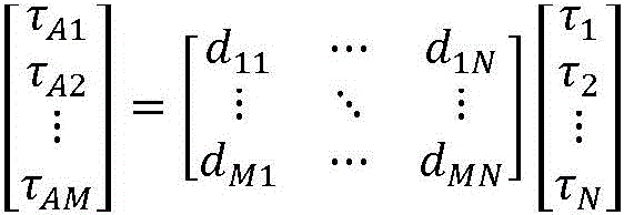
过程700的一个实施例中的控制系统650激活致动器640。如关于步骤735所述,可以确定要施加到传动系统620的远侧张力或要施加到致动器640的扭矩。致动器640可以被激活以将在步骤735中计算的远侧张力或扭矩施加到相应的传动系统620。
可替代地,可以如步骤740和745所示来确定对远侧张力的校正。特别地,步骤740计算校正张力TPROX,其取决于基于期望关节速度计算的期望传动速度向量


步骤750组合远侧张力TDIST和任何校正TPROX或TPAIR来确定由致动器施加的组合张力T。通常,如果计算的远侧张力TDIST与校正TPROX和TPAIR之和大于或小于所期望的最大值或最小值(如上参考图5D所述),则可以限制组合张力T的每个分量T1至TM在最大张力TMAX或最小张力TMIN下饱和。结果,所有张力T1至TM不小于张力TMIN或不大于最大张力TMAX。然后,在过程700返回到步骤710并读取新的关节位置之前,步骤755和760激活致动器640以在时间间隔Δt内施加并保持组合的张力T。在大约4ms或更短的间隔内(其对应于250Hz或更高的频率)保持张力可以为医疗过程提供器械的平稳移动。在一些实施方式中,时间间隔Δt为0.1ms至4ms,例如,0.1ms至1ms、1ms至2ms、2ms至3ms、或3ms至4ms。Step 750 combines the distal tension T DIST and any corrections T PROX or T PAIR to determine the combined tension T applied by the actuator. In general, each component T of the combined tension T can be limited if the sum of the calculated distal tension T DIST and the corrected T PROX and T PAIR is greater or less than the desired maximum or minimum value (as described above with reference to FIG. 5D ) 1 to TM saturates at maximum tension T MAX or minimum tension T MIN . As a result, all the tensions T 1 to TM are not less than the tension T MIN or more than the maximum tension T MAX .
医疗器械通常要求器械的工作尖端或末端执行器具有操作者诸如外科医生可控制的位置和取向。另一方面,每个关节的特定位置和取向通常对于正在执行的过程不是至关重要的,除非器械延伸穿过的管腔要求关节位置或取向。Medical devices often require a working tip or end effector of the device to have a position and orientation that is controllable by an operator, such as a surgeon. On the other hand, the specific position and orientation of each joint is generally not critical to the procedure being performed unless the position or orientation of the joint is required by the lumen through which the instrument extends.
根据本发明的一个方面,一种用于控制多关节器械的方法是使用器械末端部分(例如,诸如末端执行器、尖端或其他可移动装置)的当前配置和期望配置之间的差异来选择通过筋束施加的张力。例如,器械末端部分的测量位置、取向、速度和角速度与器械末端部分的期望位置、取向、速度和角速度之间的差异可以控制施加到医疗器械的筋束的张力。图7B示出了根据本发明的一个实施例的控制过程700B。According to one aspect of the present invention, a method for controlling a multi-joint instrument is to use a difference between a current configuration and a desired configuration of an instrument end portion (eg, such as an end effector, tip, or other movable device) to select a pass through Tension applied by tendons. For example, the difference between the measured position, orientation, velocity, and angular velocity of the device tip portion and the desired position, orientation, velocity, and angular velocity of the device tip portion can control the tension applied to the tendons of the medical device. Figure 7B shows a control process 700B according to one embodiment of the present invention.
过程700B采用与过程700相同的步骤中的一些,并且这些步骤在图7A和图7B中具有相同的附图标记。过程700B在步骤710中例如从一个或多个传感器确定关节位置θ和关节速度

在另一实施例中,可以使用传感器(例如,形状传感器)来直接测量笛卡尔位置和取向,如Giuseppe M.Prisco的标题为“Fiber optic shape sensor”的美国专利申请公布号20090324161中所述,其通过引用并入本文。与配置坐标随时间的变化相关联的平移速度可以使用在不同时间处的测量值来计算。与平移速度不同,由于量的角度性质,不能简单地通过微分方法来计算角速度。然而,计算与取向变化相关的角速度的方法是本领域已知的,并且例如由L.Sciavicco和B.Siciliano,“Modelling and Control of RobotManipulators”,Springer 2000,第109-111页描述。In another embodiment, a sensor (eg, a shape sensor) can be used to directly measure Cartesian position and orientation, as described in US Patent Application Publication No. 20090324161 entitled "Fiber optic shape sensor" by Giuseppe M. Prisco, It is incorporated herein by reference. The translational velocity associated with the change in configuration coordinates over time can be calculated using measurements at different times. Unlike translational velocity, angular velocity cannot be calculated simply by differential methods due to the angular nature of the quantity. However, methods of calculating the angular velocity associated with changes in orientation are known in the art and are described, for example, by L. Sciavicco and B. Siciliano, "Modelling and Control of Robot Manipulators", Springer 2000, pp. 109-111.
过程700B在步骤722中计算尖端误差。尖端误差指示尖端的当前配置与尖端的期望配置之间的差异。在一个实施例中,步骤722包括计算尖端的期望笛卡尔坐标与尖端的当前笛卡尔坐标之间的位置误差或差异ePOS、尖端的期望平移速度与尖端的当前平移速度之间的平移速度误差或eVT、尖端的期望取向坐标与尖端的当前取向坐标之间的取向误差或差异eORI,以及尖端的期望角速度和尖端的当前角速度之间的角速度误差或差异eVA。与位置误差ePOS不同,由于量的角度性质,不能简单地通过微分方法来计算取向误差eORI。然而,计算取向变化的方法在本领域中是已知的,并且可以在机器人技术文献中找到,例如L.Sciavicco和B.Siciliano,“Modelling and Control of Robot Manipulators”,Springer,2000年,第109-111页。Process 700B calculates the tip error in step 722 . Tip error indicates the difference between the current configuration of the tip and the desired configuration of the tip. In one embodiment, step 722 includes calculating the position error or difference e POS between the desired Cartesian coordinates of the tip and the current Cartesian coordinates of the tip, the translation velocity error between the desired translation velocity of the tip and the current translation velocity of the tip or eVT , the orientation error or difference eORI between the tip's desired orientation coordinates and the tip's current orientation coordinates, and the angular velocity error or difference eVA between the tip's desired angular velocity and the tip's current angular velocity. Unlike the position error e POS , the orientation error e ORI cannot be calculated simply by differential methods due to the angular nature of the quantity. However, methods for calculating changes in orientation are known in the art and can be found in the robotics literature, eg L. Sciavicco and B. Siciliano, "Modelling and Control of Robot Manipulators", Springer, 2000, p. 109 - 111 pages.
在步骤724中,过程700B确定旨在将尖端从当前配置移动到期望配置的尖端力FTIP和尖端扭矩τTIP。在本发明的该实施例中,尖端力FTIP取决于误差ePOS和eVT。例如,可以使用方程6计算尖端力FTIP的每个分量FX、FY或FZ,其中gpi和gvi是增益因子并且Cfi是常数。尖端扭矩τTIP可以以类似的方式确定,其中尖端扭矩τi的每个分量为误差eORI和eVA与另一组增益因子和常数gorii、gvai和Cτi的函数,如方程7所示。通常,与不同力或扭矩分量Fi和τi相关联的增益因子gpi和gvi可以不同。尖端力FTIP和尖端扭矩τi的每个分量具有独立的增益因子和常数在指定末端执行器或器械尖端的动态行为方面提供了灵活性,从而增强了器械与组织的有效相互作用。例如,当将器械导航到小管腔时,可以将垂直于插入方向的尖端力的增益因子设置为低值,而沿插入方向的增益因子设置为高值。这样一来,该器械对于插入具有足够的刚度,同时对组织的侧向阻力低,从而防止了对周围组织的损害。另一个示例,当使用器械沿一定方向在组织中打孔时,使尖端扭矩的增益因子以及沿尖端力插入方向的增益因子的值为高,这将有助于打孔任务。In step 724, process 700B determines the tip force F TIP and tip torque τ TIP intended to move the tip from the current configuration to the desired configuration. In this embodiment of the invention, the tip force F TIP depends on the errors e POS and e VT . For example, each component F X , F Y or F Z of the tip force F TIP can be calculated using Equation 6, where g pi and g vi are gain factors and C fi is a constant. The tip torque τ TIP can be determined in a similar manner, where each component of the tip torque τ i is a function of the errors e ORI and e VA with another set of gain factors and constants g orii , g vai and C τ i , as in Equation 7 Show. In general, the gain factors gpi and gvi associated with the different force or torque components F i and τ i may be different. Having independent gain factors and constants for each component of tip force F TIP and tip torque τ i provides flexibility in specifying the dynamic behavior of the end effector or instrument tip, thereby enhancing effective instrument-tissue interaction. For example, when navigating the instrument to a small lumen, the gain factor for tip force perpendicular to the insertion direction can be set to a low value, while the gain factor along the insertion direction is set to a high value. In this way, the instrument has sufficient rigidity for insertion with low lateral resistance to tissue, thereby preventing damage to surrounding tissue. As another example, when an instrument is used to punch a hole in tissue in a certain direction, having the value of the gain factor for tip torque and the gain factor along the direction of insertion of tip force to be high will help the punching task.
方程6:Fi=gpi*ePOS+gvi*eVT+Cfi Equation 6: F i =gp i *e POS +gv i *e VT +Cf i
方程7:τi=gorii*eORI+gvai*eVA+Cτi Equation 7: τ i = gori i *e ORI +gva i *e VA +Cτ i
步骤732确定将提供在步骤724中确定的尖端力FTIP和尖端扭矩τTIP的一组关节扭矩。关节扭矩向量τ、尖端力FTIP和尖端扭矩τTIP之间的关系是有据可查的,并且通常如方程8所述,其中JT是器械的运动链的众所周知的雅可比矩阵J的转置。Step 732 determines a set of joint torques that will provide the tip force F TIP and tip torque τ TIP determined in step 724 . The relationship between the joint torque vector τ, tip force F TIP and tip torque τ TIP is well documented and is generally described as Equation 8, where J T is the rotation of the well-known Jacobian matrix J of the kinematic chain of the instrument. set.
方程8: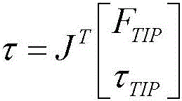
雅可比矩阵J取决于器械的几何形状以及在步骤710中确定的当前关节位置,并且可以使用已知方法进行构造。例如,John J.Craig,“Introduction to Robotics:Mechanics and Control”,Pearson Education Ltd.(2004)(其通过引用并入本文)描述了可用于构造机器人机构的雅可比矩阵的技术。在一些情况下,如果在医疗器械中提供了额外或冗余的运动自由度(例如,多于尖端的六个运动自由度),则提供尖端力FTIP和尖端扭矩τTIP的一组关节扭矩不是唯一的,并且可以使用约束条件来选择一组具有期望属性的关节扭矩,例如,选择一组关节扭矩,其防止关节在运动范围或支撑负载范围内达到其机械关节极限,或在操作过程中对器械的任何特定关节施加额外的效用。例如,可以通过选择最小化与雅可比矩阵JT转置相关的零距离与中程关节位置的偏差的一组关节扭矩来防止关节达到其机械关节极限。该组关节扭矩可以根据方程9进行选择。在方程9中,P(θ)是定义将由解提供的加法工具的势函数,

方程9: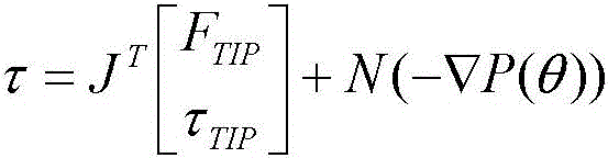
步骤732之后的过程700B以与上述过程700相同的方式进行。特别地,基于在步骤732中确定的关节扭矩,步骤735确定张力TDIST。步骤740和745确定对张力TDIST的校正TPROX和TPAIR,并且步骤750确定组合的张力向量T。然后,步骤755和760将组合的张力向量T的分量施加并保持在传动系统上,以在时间间隔Δt期间致动医疗器械。Process 700B following step 732 proceeds in the same manner as
图7A和图7B的过程700和700B需要确定将产生一组特定关节扭矩的张力。用于单个隔离关节的筋束张力可以简单地通过将关节扭矩除以施加张力处的力矩臂而根据关节扭矩来确定。在多关节的情况下,由于传动系统的几何形状以及致动线缆中的线缆布线和冗余性,问题在于求解具有约束的方程组。在一个特定实施例中,在求解方程组时可以施加非负的筋束张力约束(或最小张力约束),以防止传输系统中的线缆或其他筋束松弛。问题的输入是所确定的每个关节的关节扭矩,而线缆布线的几何形状则定义了方程组(或方程4的耦合矩阵A)。需要适当的筋束张力才能满足方程4且大于最小张力约束。The
在一些示例中,可以使用称为SIMPLEX方法的标准优化方法来处理具有不等式和最优性约束的该矩阵逆问题。SIMPLEX方法可能需要相对较长的计算时间并可能不利于实时应用。此外,SIMPLEX方法不能保证在关节扭矩变化时解的连续性。为了加快计算效率并提供连续输出解,可以考虑依赖耦合矩阵A的三角性质的迭代方法。图8A、图8B、图8C、图9A、图9B、图9C、图9D和图9E示出了多关节器械中的关节的几个特定示例,并在本文中用于说明方程4中的耦合矩阵A的一些属性。In some examples, this matrix inverse problem with inequality and optimality constraints can be handled using a standard optimization method called the SIMPLEX method. The SIMPLEX method may require relatively long computation time and may be disadvantageous for real-time applications. Furthermore, the SIMPLEX method cannot guarantee the continuity of the solution when the joint torque changes. To speed up computation efficiency and provide continuous output solutions, iterative methods that rely on the triangular nature of the coupling matrix A can be considered. 8A, 8B, 8C, 9A, 9B, 9C, 9D, and 9E illustrate several specific examples of joints in multi-joint instruments and are used herein to illustrate the coupling in Equation 4 Some properties of matrix A.
使用本文描述的优化方法可以强制执行各种约束。如果致动器的数量M大于关节的数量N,则可以利用器械600的冗余自由度中的一个来强制执行最小张力TMIN。在一些示例中,可以强制执行最小张力TMIN,以使得每个传动系统620中的张力大于或等于最小张力TMIN。可以选择要施加的扭矩τA1至τAM以在每个传动系统620中强制执行最小张力TMIN。就此而言,致动器扭矩τA1至τAM均可以被一定量的张力偏置以实现高于最小张力TMIN的此类张力。致动器640可以被控制为基于位置和速度误差两者并且基于偏移张力而将张力施加到传动系统620,该偏移张力使施加的张力不小于最小张力TMIN。这可以例如在外科手术过程期间抑制传动系统620中的松弛,从而改善器械600的响应性。Various constraints can be enforced using the optimization methods described in this paper. If the number M of actuators is greater than the number N of joints, then one of the redundant degrees of freedom of the instrument 600 can be utilized to enforce a minimum tension T MIN . In some examples, the minimum tension T MIN may be enforced such that the tension in each
在一些示例中,由独立于关节610的位置的参数来提供偏移张力,使得参数的变化不影响关节610上的净扭矩,并因此不影响关节610的定位。该参数取决于关节610的位置。结果,致动器640可以被驱动以保持参数的特定值或参数的特定值范围而不会影响关节扭矩。如果基于所确定的扭矩τA1至τAM来控制致动器640,则可以选择偏置参数τBIAS以偏移由致动器640施加的扭矩,从而偏移施加到传动系统620的张力。偏置参数τBIAS因此提供了施加到传动系统620的偏移张力。在缺乏偏置参数τBIAS(例如,当偏置参数τBIAS等于零时)的情况下,施加到传动系统620的所得基线张力仅基于关节610的位置误差,而不基于偏移张力或其他基于约束的张力。在偏置参数τBIAS为非零值的情况下,施加到传动系统620的所得张力基于关节610的位置误差并且基于偏移张力。In some examples, the offset tension is provided by a parameter independent of the position of the joint 610 , such that changes in the parameter do not affect the net torque on the joint 610 , and thus the positioning of the joint 610 . This parameter depends on the position of the joint 610 . As a result, the
选定的偏置参数τBIAS可以为张力T1至TM中的每一个提供对应的偏移张力。例如,在一些情况下,多个偏移张力彼此相等。可替代地或附加地,多个偏移张力彼此不同。在一些情况下,所有偏移张力彼此相等,并且在其他情况下,所有偏移张力彼此不相等。The selected bias parameter τ BIAS may provide a corresponding bias tension for each of the tensions T 1 to TM . For example, in some cases, the plurality of offset tensions are equal to each other. Alternatively or additionally, the plurality of offset tensions are different from each other. In some cases, all offset tensions are equal to each other, and in other cases, all offset tensions are not equal to each other.
举例来说,偏置参数τBIAS可以形成方程组的一部分以提供偏移张力。该方程组(包括与关节位置和致动器位置有关的方程)被扩展以包括附加方程,该附加方程用作对传动系统620的张力T1至TM的约束。该附加方程提供了偏移张力,其将施加的张力T1至TM偏置为不小于最小张力TMIN。例如,该附加方程由表示张力自由度的θT(在下面的方程2A中)与致动器位置θA1至θAM之间的关系来定义。尽管θ1至θN对应于关节610的物理位置,但是θT不对应于关节的物理位置,而是对应于张力自由度θT,其可调节以引起传动系统620中的对应张力。方程2A(θ=CθA)对应于由可用于强制执行最小张力TMIN的附加方程扩展的方程2,如由系数bT1至bTM和变量θT表示。矩阵C对应于方程2的完整矩阵,其具有张力自由度θT的附加系数bT1至bTM。选择矩阵C的分量,使得至少一个列与其他列线性独立,例如,对应于张力自由度θT的列。这种线性独立性可以确保最小张力约束的强制执行不会引起关节位置或施加到关节的净扭矩的对应变化。例如,线性独立性确保响应于张力自由度θT的变化而位置θ1至θN保持不变。For example, the bias parameter τ BIAS may form part of a system of equations to provide bias tension. This system of equations (including equations related to joint position and actuator position) is expanded to include additional equations that serve as constraints on the tensions T 1 to TM of the
方程2A:
待施加的致动器扭矩τA1至τAM与关节扭矩τ1至τN之间的关系可以由方程5A表示。如上所述,可以通过采用方程2A的耦合矩阵C的转置来确定具有针对索引I=1至N并且针对索引J=1至M的系数d11至dMN的矩阵D。可以选择偏置参数τBIAS以提供偏移张力,该偏移张力使得要施加的致动器扭矩τA1至τAM中的每一个都大于最小扭矩τMIN(例如,对应于最小张力TMIN)。The relationship between the actuator torques τ A1 to τ AM to be applied and the joint torques τ 1 to τ N can be represented by Equation 5A. As described above, matrix D with coefficients d 11 to d MN for indices I=1 to N and for indices J=1 to M can be determined by taking the transpose of the coupling matrix C of Equation 2A. The bias parameter τ BIAS may be selected to provide an offset tension such that each of the actuator torques τ A1 to τ AM to be applied is greater than the minimum torque τ MIN (eg, corresponding to the minimum tension T MIN ) .
如方程5A所示,施加的致动器扭矩τA1至τAM可以等于基线扭矩和偏置扭矩之和。基线扭矩对应于在没有最小张力约束的情况下要施加到致动器640的扭矩。基线扭矩和所施加的致动器扭矩τA1至τAM两者都引起施加到传动系统620的张力,这些张力减小了当前配置与期望配置之间的差异。换句话说,基线扭矩和致动器扭矩τA1至τAM在施加时在关节610处生成期望的净扭矩。偏置扭矩对应于要施加到致动器640的附加扭矩,以确保致动器扭矩τA1至τAM均大于最小扭矩τMIN。偏置扭矩不会影响当前配置。换句话说,当偏置扭矩施加到传动系统620时,其向传动系统620提供偏移张力并且在关节610处生成零净扭矩。偏置扭矩向传动系统620提供偏移张力,以使得保持由传动系统620经历的张力的平均值。因此,关节610上的净扭矩不受偏移张力影响。As shown in Equation 5A, the applied actuator torques τ A1 to τ AM may be equal to the sum of the baseline torque and the bias torque. The baseline torque corresponds to the torque to be applied to the
在一些示例中,在使用方程5A时,偏置参数τBIAS可以是使得扭矩τA1至τAM中的每个大于最小扭矩τMIN所需要的最小值。在选择偏置参数τBIAS的最小值的过程的示例中,对于每个致动器扭矩τA1至τAM,确定添加到基线扭矩的偏移扭矩。对于每个致动器扭矩τA1至τAM,确定对应的偏移扭矩,以使致动器扭矩大于最小扭矩τMIN。这些附加扭矩中的最大值被用于确定偏置参数τBIAS,以使扭矩τA1至τAM中的每个都大于最小扭矩τMIN。这确保了偏置参数τBIAS是其最小要求值,以强制执行最小张力和扭矩约束。结果,通过强制执行最小扭矩τMIN,扭矩τA1至τAM中的一个或多个等于最小扭矩τMIN,并且扭矩τA1至τAM的剩余扭矩大于最小扭矩τMIN。在一些情况下,扭矩τA1至τAM中的多个扭矩等于最小扭矩τMIN。特别地,选择扭矩τA1至τAM以抑制所有传动系统620中的松弛并且将传动系统620中的张力保持在最小张力TMIN以上。In some examples, the bias parameter τ BIAS may be the minimum value required to make each of the torques τ A1 through τ AM greater than the minimum torque τ MIN when using Equation 5A. In an example of a process for selecting a minimum value for the bias parameter τ BIAS , for each actuator torque τ A1 to τ AM , a bias torque to add to the baseline torque is determined. For each actuator torque τ A1 to τ AM , the corresponding offset torque is determined such that the actuator torque is greater than the minimum torque τ MIN . The maximum of these additional torques is used to determine the bias parameter τ BIAS such that each of the torques τ A1 to τ AM is greater than the minimum torque τ MIN . This ensures that the bias parameter τ BIAS is at its minimum required value to enforce minimum tension and torque constraints. As a result, by enforcing the minimum torque τ MIN , one or more of the torques τ A1 to τ AM is equal to the minimum torque τ MIN , and the residual torque of the torques τ A1 to τ AM is greater than the minimum torque τ MIN . In some cases, multiple of the torques τ A1 to τ AM are equal to the minimum torque τ MIN . In particular, torques τ A1 to τ AM are selected to suppress slack in all
方程5A: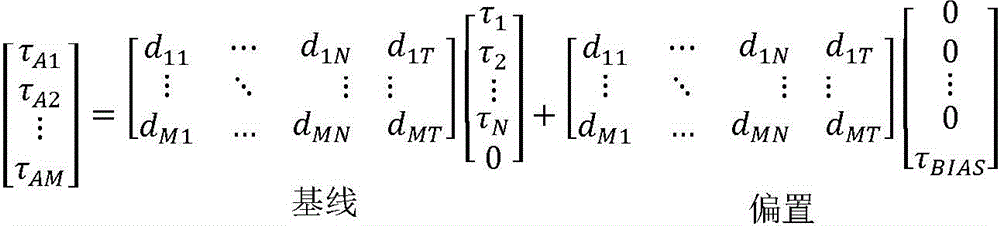
在一些实施方式中,由于关节610和致动器640的期望位置和测量位置、速度和/或扭矩中的变化导致达到不小于最小张力TMIN的张力所需的偏置扭矩变化,因此在外科手术过程中动态地改变偏置参数τBIAS。就此而言,偏置参数τBIAS可以在每个测量间隔变化。当偏置参数τBIAS动态变化时,虽然传动系统620中的张力可以在测量间隔之间变化,但是传动系统620中的张力的平均值(例如,传动系统620中的张力的均值)在不同的测量间隔之间被保持。偏置扭矩向传动系统620提供偏移张力,使得由传动系统620经历的张力的平均值被保持。In some embodiments, the change in bias torque required to achieve a tension not less than the minimum tension TMIN due to changes in the desired and measured positions, speeds, and/or torques of the joint 610 and
通过偏置参数τBIAS调节的扭矩τA1至τAM被施加以在传动系统620中生成对应的张力T1至TM。由于偏置参数τBIAS的增加,张力T1至TM中的每个的值可以增加。结果,使用偏置参数τBIAS调节致动器扭矩τA1至τAM会导致更高的张力T1至TM。即使偏置参数τBIAS被选择为其最小要求值,偏置参数τBIAS也可能由于一个传动系统中的松弛而继续增加,从而引起其他传动系统的张力的高值。例如,为了实现关节610的期望配置,可以将传动系统620中的第一传动系统驱动至较高的张力值,而将传动系统620中的第二传动系统释放至较低的张力值。第二传动系统620中的张力可以减小到在动态地控制偏置参数τBIAS的实施方式中增加偏置参数τBIAS以将第二传动系统620中的张力保持在最小张力TMIN以上的程度。结果,由于偏置参数τBIAS的增加,第一传动系统620可能经历张力的增加。The torques τ A1 to τ AM adjusted by the bias parameter τ BIAS are applied to generate corresponding tensions T 1 to TM in the
在此针对图11描述其中动态改变偏移张力的示例过程1100。此外,在此针对图11的过程1100描述了对传动系统强制执行额定张力而不是最小张力TMIN的进一步示例。在这些示例中,偏置参数τBIAS可以用于强制执行额定张力。An example process 1100 in which offset tension is dynamically changed is described herein with respect to FIG. 11 . Additionally, a further example of enforcing nominal tension on the driveline rather than minimum tension T MIN is described herein with respect to process 1100 of FIG. 11 . In these examples, the bias parameter τ BIAS can be used to enforce the rated tension.
在外科手术的一部分期间或在整个外科手术期间,可以静态地控制偏置参数τBIAS,而不是动态地控制偏置参数τBIAS,从而即使一个或多个传动系统620中的张力减小到低于最小张力TMIN的值,也可以将偏置参数τBIAS保持在特定的期望值。例如,可以静态地控制偏置参数τBIAS以避免传动系统620中的大张力,该大张力可能增加损坏传动系统620的可能性。Rather than dynamically controlling the bias parameter τ BIAS , the bias parameter τ BIAS may be controlled statically during a portion of the surgical procedure or throughout the surgical procedure, even if the tension in one or
静态控制的偏置参数τBIAS提供恒定偏移张力,这些恒定偏移张力与传动系统620的当前张力无关,并且也与关节610的当前位置无关。所得的偏移张力可以使传动系统620的张力偏移不同量或相同量。例如,在一些情况下,恒定偏移张力中的两个或更多个彼此相等。在一些情况下,恒定偏移张力中的两个或更多个彼此不同。恒定偏移张力中的一些可以彼此相等,而恒定偏移张力中的一些可以彼此不同。The statically controlled bias parameter τ BIAS provides constant bias tensions that are independent of the current tension of the
在此类示例中,不是动态地改变偏置参数τBIAS以使得偏置参数τBIAS在每个测量间隔变化,而是针对特定的测量间隔选择偏置参数τBIAS,并且将选择的偏置参数τBIAS应用于一个或多个后续测量间隔。在一个或多个后续测量间隔中,偏置参数τBIAS仍设置为在特定测量间隔处选择的初始值。因此即使当前张力T1至TM中的一个或多个降到最小张力TMIN以下,由选择的偏置参数τBIAS提供的偏移张力在一个或多个后续测量间隔期间也保持不变。尽管当前张力T1至TM可以响应于实现关节610的期望配置而增加或减小,但是强制执行最小张力TMIN的约束仅引起在特定测量间隔期间而不是在一个或多个后续测量间隔期间改变张力T1至TM。In such an example, rather than dynamically changing the bias parameter τ BIAS such that the bias parameter τ BIAS varies at each measurement interval, the bias parameter τ BIAS is selected for a particular measurement interval, and the selected bias parameter τ BIAS is applied to one or more subsequent measurement intervals. In one or more subsequent measurement intervals, the bias parameter τ BIAS remains set to the initial value chosen at the particular measurement interval. Thus even if one or more of the current tensions T 1 to TM falls below the minimum tension T MIN , the offset tension provided by the selected bias parameter τ BIAS remains unchanged during one or more subsequent measurement intervals. Although the current tensions T 1 to T M may increase or decrease in response to achieving the desired configuration of the joint 610 , the constraint of enforcing the minimum tension T MIN only results in a particular measurement interval and not during one or more subsequent measurement intervals Change the tension T 1 to T M .
可替代地,为整个外科手术选择并保持偏置参数τBIAS。在一些示例中,基于器械600的使用次数来选择偏置参数τBIAS。如果器械600是多次使用的器械,则器械600的每次使用可以改变传动系统620的特性。例如,如果器械600包括弹簧或其他机械装置以向传动系统620提供偏移张力,则这些机械装置可以在器械600的多次使用中放松。由偏移参数τBIAS提供的软件强制偏移张力可以在每次使用之后响应于硬件强制偏移张力的放松而增加。Alternatively, the bias parameter τ BIAS is selected and maintained for the entire surgical procedure. In some examples, the bias parameter τ BIAS is selected based on the number of uses of the instrument 600 . If the instrument 600 is a multi-use instrument, each use of the instrument 600 may change the characteristics of the
在一些示例中,基于医疗操作期间器械600的扭矩范围或医疗操作期间关节610的运动范围来选择偏置参数τBIAS。例如,对于较小的扭矩范围或较小的运动范围(例如,小于关节610的整个运动范围的50%、小于40%或小于30%),可选择偏置参数τBIAS以提供较大的恒定偏移张力,从而可以更容易地实现关节610的较小操纵。特别地,更大的恒定偏移张力可以提高传动系统620的响应性,并因此允许由致动器640提供的扭矩更容易地传递至关节610。In some examples, the bias parameter τ BIAS is selected based on the torque range of the instrument 600 during the medical procedure or the range of motion of the joint 610 during the medical procedure. For example, for smaller torque ranges or smaller ranges of motion (eg, less than 50%, less than 40%, or less than 30% of the full range of motion of joint 610), the bias parameter τ BIAS may be selected to provide a larger constant The tension is offset so that smaller manipulations of the joint 610 can be achieved more easily. In particular, the greater constant offset tension may improve the responsiveness of the
在一些实施方式中,并不是对整个外科手术进行静态或动态控制,而是可以以混合方式来控制偏置参数τBIAS,其中对于外科手术的一部分静态地控制偏置参数τBIAS,并且对于外科手术的另一部分动态地控制偏置参数τBIAS。例如,当张力T1至TM均小于或等于预定阈值张力时,可以根据本文关于方程5A描述的过程来动态地控制偏置参数τBIAS。当张力T1至TM中的一个或多个大于或等于预定阈值张力时,可以静态地控制偏置参数τBIAS。例如,当张力T1至TM中的一个或多个大于或等于预定阈值张力时,将偏置参数τBIAS保持在恒定的预定值。在这种情况下,当传动系统620中的张力均小于或等于阈值张力时,偏置参数τBIAS是可变的,当传动系统620中的一个或多个中的张力大于或等于阈值张力时,偏置参数τBIAS是固定的。特别地,当偏置参数τBIAS可变时,偏置参数τBIAS根据传动系统620中的张力而变化,并且当偏置参数τBIAS固定时,不管传动系统620中的张力值如何,偏置参数τBIAS均被固定为预定值。在这种混合方法中,在较低的张力下,偏置参数τBIAS的动态控制可以抑制传动系统620中的一个或多个变得松弛。在较高的张力下,偏置参数τBIAS的静态控制可以减小张力T1至TM增加到可能损坏传动系统620的水平的可能性。In some embodiments, rather than static or dynamic control of the entire surgery, the bias parameter τ BIAS may be controlled in a hybrid manner, where the bias parameter τ BIAS is statically controlled for a portion of the surgery and Another part of the procedure dynamically controls the bias parameter τ BIAS . For example, when the tensions T 1 to TM are all less than or equal to a predetermined threshold tension, the bias parameter τ BIAS may be dynamically controlled according to the process described herein with respect to Equation 5A. The bias parameter τ BIAS may be statically controlled when one or more of the tensions T 1 to TM is greater than or equal to a predetermined threshold tension. For example, the bias parameter τ BIAS is maintained at a constant predetermined value when one or more of the tensions T 1 to TM is greater than or equal to a predetermined threshold tension. In this case, the bias parameter τ BIAS is variable when the tensions in the
可替代地,当以混合方式控制时,当张力T1至TM均大于或等于预定阈值张力时,可以根据本文关于方程5A描述的过程来动态地控制偏置参数τBIAS。如本文所述,偏置参数τBIAS可以用于强制执行额定张力而不是最小张力TMIN。例如,额定张力可以是最大张力TMAX。当张力T1至TM中的一个或多个小于或等于预定阈值张力时,可以静态地控制偏置参数τBIAS。例如,当张力T1至TM中的一个或多个小于或等于阈值张力时,将偏置参数τBIAS保持在恒定的预定值。在此类情况下,当传动系统620中的张力均大于或等于阈值张力时,偏置参数τBIAS是可变的,当传动系统620中的一个或多个中的张力小于或等于阈值张力时,偏置参数τBIAS是固定的。在这种混合方法中,在较高的张力下,偏置参数τBIAS的动态控制可以抑制传动系统620中的一个或多个超过某个最大张力TMAX。在较低的张力下,偏置参数τBIAS的静态控制可以通过施加恒定偏移张力来增加传动系统的刚度。Alternatively, when controlled in a hybrid manner, when the tensions T 1 to TM are all greater than or equal to a predetermined threshold tension, the bias parameter τ BIAS may be dynamically controlled according to the process described herein with respect to Equation 5A. As described herein, the bias parameter τ BIAS can be used to enforce nominal tension rather than minimum tension T MIN . For example, the rated tension may be the maximum tension T MAX . The bias parameter τ BIAS may be statically controlled when one or more of the tensions T 1 to TM is less than or equal to a predetermined threshold tension. For example, the bias parameter τ BIAS is maintained at a constant predetermined value when one or more of the tensions T 1 to TM is less than or equal to a threshold tension. In such cases, the bias parameter τ BIAS is variable when the tensions in the
在一些实施方式中,监测用于强制执行最小扭矩τMIN、最小张力TMIN或其他额定张力的参数以进行误差检测。例如,该参数可以对应于偏置常数τBIAS或张力自由度θT。在监视张力自由度θT以进行误差检测的示例中,张力自由度θT的变化可以指示与一个或多个传动系统620相关联的一个或多个故障。例如,因为该参数取决于致动器640的位置,但是独立于关节610的位置,如果传动系统620有故障并且没有将力从致动器640传递到关节610,则致动器640的位置可以变化而没有对应的关节610的位置变化。因此,张力自由度θT大于或等于预定阈值可以指示与传动系统620相关联的故障。例如,该故障可以对应于一个或多个传动系统620包括断裂的筋束或其他有故障的力传递构件。当传动系统620出现故障时,张力自由度θT可以增加到大于或等于预定阈值的值。例如,在使用编码器确定关节610的位置的情况下,不会直接测量关节610的位置,而将致动器640的位置用于确定关节610的位置。结果当传动系统620出现故障时,致动器640被重新定位以驱动传动系统620,即使致动器640的这种重新定位不会引起关节610重新定位。因此,致动器640被重新定位以驱动传动系统620,而不会引起在传动系统620正常运行时预期发生的关节610的位置的对应变化。致动器640继续被驱动以试图实现期望配置,并且由于不能实现期望配置,因此致动器640被驱动以使得张力自由度θT继续增加。In some embodiments, parameters for enforcing a minimum torque τ MIN , a minimum tension T MIN or other nominal tension are monitored for error detection. For example, this parameter may correspond to the bias constant τ BIAS or the tension degree of freedom θ T . In the example of monitoring the tension degrees of freedom θ T for error detection, changes in the tension degrees of freedom θ T may indicate one or more faults associated with the one or more drive trains 620 . For example, because this parameter depends on the position of the
响应于张力自由度θT大于或等于预定阈值,控制系统650控制用户输出装置(例如,扬声器、显示器、振动装置或可提供听觉、视觉或触觉反馈的其他装置)以生成警报以向操作者提供反馈。另外,控制系统650可以停止驱动致动器640,直到解决了传动系统620的故障。In response to the tension degree of freedom θ T being greater than or equal to a predetermined threshold, the
在一些实施方式中,控制系统650不是响应于张力自由度θT的值大于或等于预定阈值而发出警报,而是响应于张力自由度θT的变化率大于或等于预定阈值而发出警报。当传动系统620损坏时,该变化率可以迅速增加,因为传动系统620在损坏时不提供致动器640为了重新定位关节610将必须驱动抵顶的阻力。此外,因为关节610不能在致动器640被驱动时实现期望配置,所以控制系统650可以继续驱动致动器640,从而使张力自由度θT的值和变化率增大。监视这些值并在它们大于或等于预定值时提供警报可以确保能够检测到与传动系统620相关的故障。In some embodiments, the
虽然与方程5A相关联的过程基于致动器640的位置和关节610的位置来控制偏置扭矩,但是在一些实施方式中,基于阻尼函数来选择致动器扭矩τA1至τAM和传动系统张力T1至TM。致动器640的当前速度中的一个或多个被确定。基于一个或多个当前速度,阻尼函数被确定。阻尼函数由一个或多个参数(诸如阻尼系数、固有频率或其他可用于对致动器640和关节610的移动提供阻尼作用的适当参数)来定义。选择阻尼函数以抑制致动器640的位置的突然改变,并因此抑制关节610的移动的突然改变。当致动器640以高速操作时,可以引入阻尼函数以减小张力。例如,在致动器640在一个方向上被驱动并且然后在不同方向上被快速驱动或者被驱动以使得传动系统620的刚度被快速减小的情况下,致动器运动的快速变化会导致传动系统620的线缆或筋束松弛。这可能导致线缆或筋束从致动器640松开。可以引入阻尼函数以防止这种情况发生。While the process associated with Equation 5A controls the bias torque based on the position of the
例如,图8A示出了包含多个机械关节810、820和830的器械的一部分。每个关节810、820或830提供单个自由度,该自由度对应于围绕关节的轴线z1、z2或z3的旋转。在图8A中,筋束C1和C2连接到关节810以致动关节810。筋束C3和C4穿过关节810并连接到关节820以致动关节820。筋束C5和C6穿过关节810和820并连接到关节830以致动关节830。可以通过诸如图2或图3A所示的顺应性传动系统将筋束C1至C6的近端(未示出)连接至相应的驱动马达或其他致动器。器械的控制系统控制致动器以在筋束C1、C2、C3、C4、C5和C6中施加相应的张力T1、T2、T3、T4、T5和T6。For example, FIG. 8A shows a portion of an instrument that includes multiple
在所示的实施例中,关节830位于器械的远端处,并且可以使用诸如上文参考图5A、图5B、图5C和图5D所述的单关节过程来控制关节830的致动。然而,关节820上的总扭矩不仅取决于线缆C3和C4中的张力,还取决于由连接到关节830的筋束C5和C6施加的扭矩。类似地,关节810上的总扭矩不仅取决于筋束C1和C2中的张力,还取决于由连接到更靠近远端的关节820和830的筋束C3、C4、C5和C6施加的扭矩。可以开发基于器械的几何或运动学特性的模型来将关节810、820和830上的扭矩τ1、τ2和τ3与筋束中的张力T1、T2、T3、T4、T5和T6相关联。方程4A示出了一个此类数学模型,并提供了上面方程4的特定示例。在方程4A中,τ1、τ2和τ3是关节810、820和830上的相应致动扭矩,r1、r2和r3是筋束C1、C3和C5附接的有效力矩臂,并且T1、T2、T3、T4、T5和T6是相应筋束C1、C2、C3、C4、C5和C6中的张力。引出方程4A的模型应用于包括关节810、820和830的器械的一组特定几何或机械特性,包括:旋转轴线z1、z2和z3平行并且位于同一平面中;筋束C1和C2、C3和C4或C5和C6分别附接在有效力矩臂r1、r2或r3处;并且筋束C1、C3和C5分别在与筋束C2、C4和C6的操作相反的旋转方向上在相应关节810、820和830上操作。In the illustrated embodiment, the joint 830 is located at the distal end of the instrument, and actuation of the joint 830 can be controlled using a single-joint process such as that described above with reference to FIGS. 5A, 5B, 5C, and 5D. However, the total torque on joint 820 depends not only on the tension in cables C3 and C4 , but also on the torque applied by tendons C5 and C6 connected to joint 830 . Similarly, the total torque on joint 810 depends not only on the tension in tendons C1 and C2, but also on the torque applied by tendons C3, C4, C5 and C6 connected to more
方程4A:
图8B和图8C示出了医疗器械的特性,该医疗器械包括具有彼此垂直的相应旋转轴线z1和z2的关节810和820。通常,每个关节810和820处的净扭矩取决于穿过关节到远端的筋束中的张力以及相对于关节的致动轴线与筋束相关联的有效力矩臂。图8C示出了关节810的底视图以说明典型示例,其中每个筋束C1、C2、C3和C4在不同力矩臂处绕轴线z1和z2进行操作。将关节810和820视为隔离系统或器械远端上的最后两个致动关节,关节810和820上的净扭矩τ1和τ2与相应的筋束C1、C2、C3和C4中的张力T1、T2、T3和T4有关,如方程4B所指示。特别地,关节820承受净扭矩τ2,该净扭矩τ2取决于筋束C3中的张力T3和相对于轴线z2的力矩臂a32(在该力矩臂a32处筋束C3附接到关节820),并且取决于筋束C4中的张力T4和相对于轴线z2的力矩臂a42(在该力矩臂a42处筋束C4附接到关节820)。关节810上的扭矩τ1取决于附接到关节810的筋束C1和C2中的张力T1和T2、附接到关节820的筋束C3和C4中的张力T3和T4,以及力矩臂a11、a21、a31和a41。力矩臂a21和a41被分配负号,因为牵拉筋束C2和C4在与关节810上的扭矩τ1的约定定义的正方向相反的方向上产生了旋转。出于相同的原因,力矩臂a31也被分配负号,因为牵拉筋束C3引起了与关节820的正向旋转方向相反的旋转。Figures 8B and 8C illustrate the properties of a medical
方程4B: Equation 4B:
应当理解的是,当关节轴线彼此既不平行也不垂直,而是处于任意相对取向时,可以采用类似的方法来计算方程4中的矩阵A,方法是相应地计算每个筋束相对于每个关节轴线的力矩臂。It should be understood that when the joint axes are neither parallel nor perpendicular to each other, but are in any relative orientation, a similar method can be used to calculate the matrix A in Equation 4 by correspondingly calculating each tendon relative to each moment arm of each joint axis.
图9A示出了器械的一部分900,该器械包括连续柔性关节910,诸如在医疗导管、用于胃肠道、结肠和支气管的内窥镜、导丝以及一些其他内窥镜器械(诸如用于组织取样的抓紧器和针头)中常见的柔性关节910。关节910类似于上面参考图3B所描述的柔性结构。然而,通过使用三个或更多个筋束920操纵关节910,以提供具有两个运动自由度的关节。例如,图9B示出了一个实施例的底视图,其中在图9B中标记为c1、c2、c3和c4的四个筋束920连接至柔性关节910的末端。筋束c1和c2中的张力差可以在第一方向上转动关节910,例如引起绕X轴的旋转,并且筋束c3和c4中的张力差可以在正交于第一方向的第二方向上转动关节910,例如引起绕Y轴的旋转。趋向于使关节910弯曲的净扭矩的分量τX和τY可以分别根据方程4C中指示的筋束c1、c2、c3和c4中的张力T1、T2、T3和T4确定。如从方程4C可见,扭矩分量τX和τY的方程没有耦合,因为分量τX仅取决于张力T1和T2并且分量τY仅取决于张力T3和T4。Figure 9A shows a
方程4C: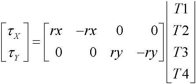
图9C示出了使用三个筋束920(在图9C中被标记为c1、c2和c3)来致动关节910的实施例的底视图。在这种配置下,趋向于使关节910弯曲的净扭矩的分量τX和τY可以分别根据筋束c1、c2和c3中的张力T1、T2和T3来确定,如方程4D所指示,其中ra是绕X轴的筋束c1的力矩臂,-rb是绕X轴的筋束c2和c3的力矩臂,并且rc和-rc是绕Y轴的筋束c2和c3的相应力矩臂。按惯例,绕X轴的c2和c3筋束的力矩臂被分配负号,因为牵拉筋束c2和c3将使关节910在与拉动筋束c1使关节910绕X轴弯曲的方向相反的方向上弯曲。出于同样的原因,筋束c3的绕Y轴的力矩臂按惯例被分配负号。Figure 9C shows a bottom view of an embodiment that uses three tendons 920 (labeled cl, c2, and c3 in Figure 9C) to actuate the joint 910. In this configuration, the components τ X and τ Y of the net torque tending to bend the joint 910 can be determined from the tensions T1 , T2 and T3 in the tendons c1 , c2 and c3 , respectively, as indicated by Equation 4D, where ra is the moment arm of tendon c1 about the X-axis, -rb is the moment arm of tendons c2 and c3 about the X-axis, and rc and -rc are the corresponding moment arms of tendons c2 and c3 about the Y-axis. By convention, the moment arms of the c2 and c3 tendons about the X-axis are assigned a negative sign, because stretching the tendons c2 and c3 will cause the joint 910 to bend in the opposite direction to the direction in which pulling the tendon c1 bends the joint 910 about the X-axis Bend up. For the same reason, the moment arm about the Y-axis of tendon c3 is conventionally assigned a negative sign.
方程4D: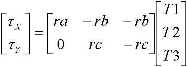
图9D示出了一个实施例,其中柔性器械950(例如,柔性导管)包含两个关节。通过筋束920致动关节910以提供两个运动自由度,并且通过筋束930致动关节940以提供另外两个运动自由度。图9E示出了在特定情况下的关节940的基部,其使用三个筋束920(在图9E中标记为c1、c2和c3)用于关节910,并且使用三个筋束930(在图9E中标记为c4、c5和c6)用于关节940。可以使用上面的方程4D对最远侧关节910中的扭矩和力之间的关系进行建模。但是,关节940中的扭矩取决于穿过关节940的所有筋束920和930中的张力。在该示例中,关节940是使用柔性节段实现的。因此,在一个特定的示例中,如方程4E所示,器械950中的扭矩和张力可能相关。在方程4E中,τ1X和τ1Y是关节910中的扭矩分量,并且τ2X和τ2Y是关节940中的扭矩分量,ra、rb和rc是力矩臂的量值,T1、T2和T3是筋束920中的张力,并且T4、T5和T6是筋束930中的张力。Figure 9D shows an embodiment in which a flexible instrument 950 (eg, a flexible catheter) contains two joints.
方程4E: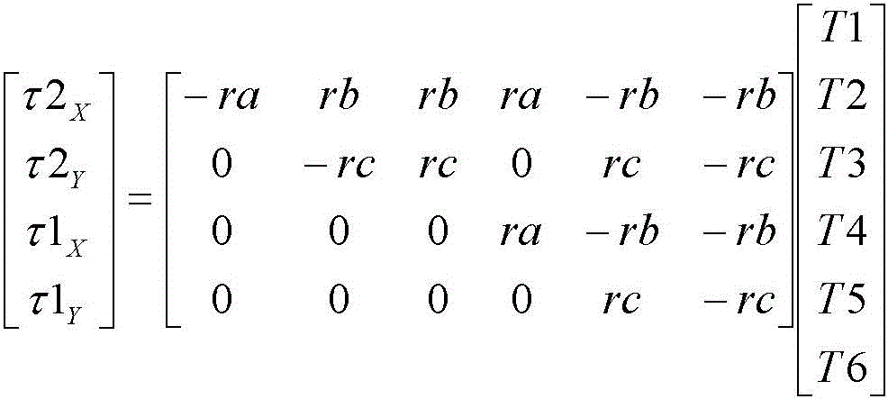
方程4A至4E示出了在许多医疗器械中可以独立于系统中的其他张力来解决寻找在最远侧关节中提供特定扭矩的张力的问题。更具体地,每个关节的关节扭矩取决于连接到该关节的筋束中的张力以及施加到更远侧关节的张力。因此,可以使用以下过程来执行图7A和图7B的过程700和700B的步骤735:从器械的远端朝向器械的近端按顺序迭代地分析关节,以确定产生一组给定关节扭矩的一组张力。Equations 4A to 4E show that in many medical devices the problem of finding a tension that provides a particular torque in the most distal joint can be solved independently of other tensions in the system. More specifically, the joint torque of each joint depends on the tension in the tendons connected to that joint as well as the tension applied to the more distal joints. Accordingly, step 735 of
图10示出了一个实施例,其中器械1000包括三个关节1010-1、1010-2、1010-3(统称为关节1010)。每个关节1010通过四个筋束1020-1、1020-2、1020-3、1020-4(统称为筋束1020)来致动以提供运动自由度。将致动器1040-1、1040-2、1040-3、1040-4(统称为致动器1040)耦合到筋束1020使得施加到致动器1040的扭矩τA1和τA4通过筋束1020向远侧传输到关节1010。扭矩τA1至τA4在筋束1020中生成张力T1至T4。每个关节1010耦合到筋束1020中的每一个,使得在任何一根筋束1020由对应的致动器1040致动时,每个关节1010的位置被调节。扭矩τ1至τ3可以对应于俯仰扭矩、偏航扭矩和抓握扭矩。俯仰扭矩在图10中被描绘为生成垂直于偏航扭矩的运动平面的运动。当致动器1040施加扭矩τA1至τA4时,扭矩τ1至τ3被施加到关节1010。Figure 10 shows an embodiment in which the instrument 1000 includes three joints 1010-1, 1010-2, 1010-3 (collectively referred to as joints 1010). Each joint 1010 is actuated by four tendons 1020-1, 1020-2, 1020-3, 1020-4 (collectively, tendons 1020) to provide freedom of movement. Coupling actuators 1040 - 1 , 1040 - 2 , 1040 - 3 , 1040 - 4 (collectively referred to as actuators 1040 ) to
控制系统1050可以操作致动器1040以在筋束1020中生成张力。控制系统1050可以强制执行最小张力TMIN,使得筋束1020中的每一个中的张力超过所选的最小张力TMIN。结果,可以使用方程2A推导出致动器位置与自由度之间的关系,其中致动器的数量M等于4,并且运动自由度的数量N等于3。就此而言,致动器位置θA1至θA4与自由度θ1至θ3和θT之间的关系可以使用下面的方程2B来建模(θ=CθA)。在该实施例中,θ1至θ3对应于运动自由度,例如,俯仰自由度、偏航自由度和抓握自由度。θT对应于用于将筋束1020中的张力约束为大于或等于最小张力TMIN的张力自由度。选择索引I=1至4和索引J=1至4的系数bIJ,使得与张力自由度θT相关联的列线性地独立于其他自由度。系数bIJ进一步表示致动器位置和关节位置之间的耦合。The
方程2B: Equation 2B:
方程5A可用于推导出致动器扭矩和关节扭矩之间的关系。特别地,致动器扭矩τA1和τA4与关节扭矩τ1至τ3和τBIAS之间的关系可以使用下面的方程5B来建模(τA=D[τ1,τ2,τ3,0]T+D[0,0,0,τBIAS])。方程5B的矩阵D可以通过对方程2B的耦合矩阵C进行转置来确定。可以使用关于方程5A描述的过程来确定偏置参数τBIAS。方程5B可用于确定要施加到致动器1040的致动器扭矩。Equation 5A can be used to derive the relationship between actuator torque and joint torque. In particular, the relationship between the actuator torques τ A1 and τ A4 and the joint torques τ 1 to τ 3 and τ BIAS can be modeled using Equation 5B below (τ A = D[τ 1 , τ 2 , τ 3 , 0] T + D[0, 0, 0, τ BIAS ]). The matrix D of Equation 5B can be determined by transposing the coupling matrix C of Equation 2B. The bias parameter τ BIAS can be determined using the procedure described with respect to Equation 5A. Equation 5B can be used to determine the actuator torque to be applied to the
方程5B: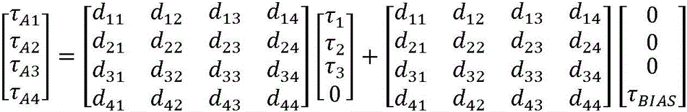
参考图11,过程1100是用于计算产生给定的一组关节扭矩的张力的迭代过程。过程1100可以使用与针对方程5A所描述的过程类似的过程,以抵消由致动器施加的扭矩,并且由此抵消施加到传动系统的张力。特别地,可选择τBIAS以提供实现特定的额定或目标张力的偏移张力。Referring to FIG. 11, process 1100 is an iterative process for calculating the tension to produce a given set of joint torques. Process 1100 may use a process similar to that described for Equation 5A to counteract the torque applied by the actuator, and thus the tension applied to the driveline. In particular, τ BIAS can be selected to provide an offset tension to achieve a particular nominal or target tension.
在图11所示的示例中,过程1100开始于对最后或最远侧关节的张力确定,然后以朝向第一或最近侧关节的顺序循序确定关节的张力。步骤1110初始化索引j,其标识用于分析的关节并且被初始设置为关节数L。然后,步骤1120获取第j个关节的扭矩τj。例如,可以按照如上所述的过程700的步骤730或过程700B的步骤732确定关节扭矩τj,并且该关节扭矩τj可以具有用于提供单个运动自由度的关节的单个非零分量,或者可以具有用于提供两个运动自由度的关节的两个非零分量。In the example shown in FIG. 11, the process 1100 begins with a determination of the tension of the last or most distal joint and then sequentially determines the tension of the joints in order towards the first or most proximal joint. Step 1110 initializes the index j, which identifies the joint for analysis and is initially set to the number of joints L. Then, step 1120 obtains the torque τ j of the jth joint. For example, the joint torque τ j may be determined as described above at
然后,步骤1130计算通过附接到第j个关节的联动装置直接施加到第j个关节的张力,以便产生例如在图7A或图7B的步骤730或732中计算出的净扭矩。在图11的示例中,步骤1130的计算是在直接施加的张力之一是目标张力或额定张力的约束下进行的。额定张力可以但不需要为零,以便释放传动系统中的张力,或者可替代地,额定张力可以是确保传动系统中的筋束不变松弛的最小张力TMIN。额定张力可以但不需要与释放致动器力的情况对应,例如,图6的致动器640靠惯性滑动,在这种情况下,张力可取决于所采用的传动系统的类型。Step 1130 then calculates the tension applied directly to the jth joint through the linkage attached to the jth joint to produce the net torque calculated, for example, in
在医疗器械中的第j个关节提供单个运动自由度并直接耦合到两个筋束或传动系统的特定情况下,关节扭矩具有通过方程4中的单个方程与张力相关联的单个分量。然后针对第L个关节或最远侧关节的步骤1130涉及求解将关节扭矩与耦合到最远侧关节的两个张力相关联的线性方程。对于涉及两个未知张力的单个线性方程,应用一个张力为额定张力的约束保证了另一张力的唯一解。具体地,另一张力可以根据最远侧关节上的扭矩和耦合矩阵A的相关系数来唯一地确定。可替代地,如果第L个关节提供两个运动自由度并耦合到三个筋束或传动系统,则关节扭矩具有两个分量,并且对应于方程4中表示的方程组中的两个方程。这两个方程涉及三个张力,因此,在张力之一等于额定张力的约束下,可以根据关节扭矩的分量和耦合矩阵A的相关分量唯一地确定另外两个张力。应当注意的是,所提出的方法在某种意义上是通用的,即以类似方式,如果m个筋束(其中m大于3)连接到提供两个自由度的同一关节,则(m-2)个张力可以同时被约束为等于额定张力,而其余两个张力将根据关节扭矩的分量和耦合矩阵A的相关分量唯一地确定。In the specific case where the jth joint in the medical device provides a single degree of freedom of motion and is directly coupled to two tendons or drive trains, the joint torque has a single component related to the tension by a single equation in Equation 4. Step 1130 for the Lth joint or the most distal joint then involves solving a linear equation relating the joint torque to the two tension forces coupled to the most distal joint. For a single linear equation involving two unknown tensions, applying the constraint that one tension is the rated tension guarantees a unique solution to the other tension. Specifically, the other tension can be uniquely determined from the torque on the most distal joint and the correlation coefficient of the coupling matrix A. Alternatively, if the Lth joint provides two degrees of freedom of motion and is coupled to three tendons or transmission systems, the joint torque has two components and corresponds to two equations in the system of equations expressed in Equation 4. These two equations involve three tensions, so under the constraint that one of the tensions is equal to the rated tension, the other two tensions can be uniquely determined from the components of the joint torque and the associated components of the coupling matrix A. It should be noted that the proposed method is general in the sense that in a similar way, if m tendons (where m is greater than 3) are connected to the same joint providing two degrees of freedom, then (m-2 ) tensions can be simultaneously constrained to be equal to the rated tension, while the remaining two tensions will be uniquely determined from the components of the joint torque and the associated components of the coupling matrix A.
初始针对最远侧关节(即,j=L)执行步骤1130。步骤1130的子步骤1132初始选择附接到最远侧关节的传动系统之一,并且子步骤1134将张力设置为最小允许张力TMIN以用于子步骤1136中的试算。子步骤1136初始计算附接到关节的其他传动系统的张力(或多个张力),并且所计算的张力仅取决于所计算的关节扭矩和直接施加到最远侧关节的其他张力。子步骤1138确定是否所有计算的张力都大于或等于最小允许张力TMIN。如果不是,则步骤1140在重复子步骤1134和1136时选择直接耦合到关节的传动系统中的另一个作为具有额定张力的传动系统。一旦步骤1140确定所计算的一个或多个张力都大于或等于最小允许张力TMIN,则最远侧关节的张力的确定完成,并且在过程1100从步骤1160分支返回以重复步骤1120之前,步骤1150递减关节索引j。Step 1130 is initially performed for the most distal joint (ie, j=L). Sub-step 1132 of step 1130 initially selects one of the transmission systems attached to the most distal joint, and sub-step 1134 sets the tension to the minimum allowable tension T MIN for trial calculation in sub-step 1136 . Sub-step 1136 initially calculates the tension (or tensions) of other drivetrains attached to the joint, and the calculated tension depends only on the calculated joint torque and other tension applied directly to the most distal joint. Sub-step 1138 determines if all calculated tensions are greater than or equal to the minimum allowable tension TMIN . If not, step 1140 selects the other of the drive systems directly coupled to the joint as the drive system with rated tension while repeating sub-steps 1134 and 1136 . Once step 1140 determines that the calculated tension or tensions are all greater than or equal to the minimum allowable tension T MIN , the determination of the tension of the most distal joint is complete, and step 1150 is completed before process 1100 branches back from step 1160 to repeat step 1120 Decrement joint index j.
在关节连接到两个传动系统并提供一个运动自由度的情况下,针对第j个关节的步骤1130涉及评估来自方程5A表示的方程组的单个方程。如上所述,耦合矩阵A的性质使得针对第j个关节的方程仅涉及直接耦合到第j个关节的张力和耦合到更多远侧关节的张力。因此,如果已经确定了更多个远侧关节的张力,则与第j个关节相关联的方程仅涉及两个未知数,它们是直接连接到该关节的传动系统中的张力。张力之一是额定张力的约束允许唯一地确定大于或等于额定张力的另一张力。第j个关节连接到三个传动系统并提供两个运动自由度的情况涉及评估与关节扭矩的两个分量相关联的两个方程。如果已经确定了更多远侧关节的张力,则与第j个关节相关联的方程仅涉及三个未知数,它们是直接连接到关节的筋束中的张力。张力之一是额定张力的约束允许唯一确定大于或等于额定张力的其他两个张力。Step 1130 for the jth joint involves evaluating a single equation from the system of equations represented by Equation 5A, where the joint is connected to two transmission systems and provides one degree of freedom of motion. As mentioned above, the nature of the coupling matrix A is such that the equation for the jth joint involves only the tension coupled directly to the jth joint and the tension coupled to more distal joints. Therefore, if the tension of more distal joints has been determined, the equation associated with the jth joint involves only two unknowns, which are the tension in the drive train directly connected to that joint. The constraint that one of the tensions is the rated tension allows the other tension greater than or equal to the rated tension to be uniquely determined. The case where the jth joint is connected to three drive trains and provides two degrees of freedom of motion involves evaluating two equations associated with the two components of joint torque. If the tensions of more distal joints have been determined, the equation associated with the jth joint involves only three unknowns, which are the tensions in the tendons directly connected to the joints. The constraint that one of the tensions is the rated tension allows unique determination of the other two tensions greater than or equal to the rated tension.
因此,图11的过程1100可以使用以从器械的远端起的关节顺序进行的张力确定来生成一组完整的远侧张力,当步骤1160确定已经评估了最近侧关节时在步骤1170中输出该组完整的远侧张力。可以使用计算机或进行操作以便实时确定张力的其他计算系统来有效地实现过程1100,该张力的变化速率为医疗程序提供足够平稳的运动,例如变化速率高达250Hz或更高。此外,每个关节在目标值或额定值处具有至少一个直接施加的张力的约束提供了以连续时间确定的张力之间的连续性。Thus, the process 1100 of FIG. 11 can generate a complete set of distal tensions using tension determinations in joint order from the distal end of the instrument, output in step 1170 when step 1160 determines that the proximal-most joint has been evaluated Complete distal tension of the group. Process 1100 can be effectively implemented using a computer or other computing system that operates to determine tension in real time at a rate of change that provides a sufficiently smooth motion for a medical procedure, eg, a rate of change of up to 250 Hz or higher. Furthermore, the constraint that each joint has at least one directly applied tension at the target or nominal value provides continuity between tensions determined in continuous time.
虽然子步骤1134被描述为将所选传动系统中的张力设置为最小张力TMIN,并且子步骤1138被描述为确定所有张力是否都高于最小张力TMIN,但在其他实施方式中,子步骤1134的额定张力不同于子步骤1138的阈值张力。额定张力可以是至少一个传动系统的目标张力,并且阈值张力可以是传动系统中所计算的张力不超过或不低于的张力。就此而言,如果阈值张力是最大张力TMAX,则阈值张力可以大于或等于额定张力,或者如果阈值张力是最小张力TMIN,则阈值张力可以小于或等于额定张力。Although sub-step 1134 is described as setting the tension in the selected transmission system to the minimum tension T MIN and sub-step 1138 is described as determining whether all tensions are above the minimum tension T MIN , in other embodiments, the sub-step The nominal tension of 1134 is different from the threshold tension of sub-step 1138 . The nominal tension may be a target tension of at least one driveline, and the threshold tension may be a tension at which the calculated tension in the driveline does not exceed or fall below. In this regard, the threshold tension may be greater than or equal to the rated tension if the threshold tension is the maximum tension TMAX , or less than or equal to the rated tension if the threshold tension is the minimum tension TMIN .
尽管关于实现高于(非零)最小张力TMIN的张力描述了步骤1130,但是在一些实施方式中,额定张力是最大允许张力TMAX或者在最小张力TMIN与最大张力TMAX之间的某个其他张力。子步骤1138不是确定所有计算的张力是否都大于或等于最小允许张力TMIN,而是确定所有计算的张力是否都小于或等于最大允许张力TMAX。在其他实施方式中,当额定张力在最大允许张力TMAX与最小允许张力TMIN之间时,所有计算的张力都大于或等于额定张力,或者所有计算的张力都小于或等于额定张力。Although step 1130 is described with respect to achieving a tension higher than the (non-zero) minimum tension T MIN , in some embodiments the nominal tension is the maximum allowable tension T MAX or something between the minimum tension T MIN and the maximum tension T MAX other tension. Instead of determining whether all calculated tensions are greater than or equal to the minimum allowable tension TMIN , sub-step 1138 determines whether all calculated tensions are less than or equal to the maximum allowable tension TMAX . In other embodiments, all calculated tensions are greater than or equal to the rated tension, or all calculated tensions are less than or equal to the rated tension when the rated tension is between the maximum allowable tension TMAX and the minimum allowable tension TMIN .
在一些实施方式中,结合过程500的一个或多个步骤来执行过程1100。例如,本文所述的校正中的任一个(诸如但不限于步骤530、535、540、550、740和745提供的那些校正)可以应用于过程1100。这些校正可以超控(override)作为步骤1130的一部分计算的张力。就此而言,可以超控在步骤1130、1150、1160中计算的张力,使得所施加的远侧张力可以与计算的张力不同。例如,如果额定张力是计算张力不会低于的最小张力TMIN或某个其他额定张力,则所计算的张力可能会以最大张力TMAX饱和,以防止传动系统因过大的张力而损坏。如果额定张力是计算张力不会超过的最大张力TMAX或某个其他额定张力,则所计算的张力可能会以最小张力TMIN饱和,以防止传动系统松弛。可以使用可存储在计算机可读介质(诸如,电子存储器或磁盘或光盘)上的软件来实现或控制本公开的上述和其他部分的过程,以便由通用计算机执行。可替代地,可以使用专用硬件或电子装置植入在上述过程中采用的控制或计算。In some implementations, process 1100 is performed in conjunction with one or more steps of
尽管已经参考特定实施例描述了本发明,但是该描述仅是本发明的应用的示例并且不应被视为限制。例如,可以控制的器械的类型在各实施方式中有所不同。图12A是根据一些实施例的医疗器械系统1200的另一示例的简化图。在一些实施例中,医疗器械系统1200可以用作在用远程操作或非远程操作医疗系统执行的图像引导医疗程序中的医疗器械。在一些示例中,医疗器械系统1200可以用于非远程操作探索程序或用于涉及传统手动操作医疗器械的程序,诸如内窥镜检查。可选地,医疗器械系统1200可以用于收集(即,测量)与诸如患者P的患者的解剖通道内的位置对应的一组数据点。Although the invention has been described with reference to specific embodiments, this description is merely an example of the application of the invention and should not be considered limiting. For example, the types of instruments that can be controlled vary from embodiment to embodiment. 12A is a simplified diagram of another example of a
医疗器械系统1200包括耦合到驱动单元1204的细长装置1202。细长装置1202包括具有近端1217和远端1218的柔性主体1216(当远端包括尖端的一部分时也被称为“尖端部分1218”)。在一些实施例中,柔性主体1216具有大约3mm的外径。其他柔性主体的外径可以更大或更小。
医疗器械系统1200进一步包括跟踪系统1230,以便使用一个或多个传感器和/或成像装置来确定远端1218处的柔性主体1216和/或沿着柔性主体1216的一个或多个区段1224的位置、取向、速度、速率、姿势和/或形状,如下文进一步详细描述。柔性主体1216在远端1218和近端1217之间的整个长度可以被有效地划分成区段1224。跟踪系统1230可以可选地被实现为与一个或多个计算机处理器交互或以其他方式由其执行的硬件、固件、软件或其组合,该计算机处理器可以包括图1中的控制系统150的处理器。The
跟踪系统1230可以可选地使用形状传感器1222跟踪远端1218和/或一个或多个区段1224。形状传感器1222可以可选地包括与柔性主体1216对准的光纤(例如,提供在内部通道内(未示出)或在外部安装)。在一个实施例中,该光纤具有约为1200μm的直径。在其他实施例中,尺寸可以更大或更小。形状传感器1222的光纤形成用于确定柔性主体1216的形状的光纤弯曲传感器。在一种替代方式中,包括光纤布拉格光栅(FBG)的光纤被用于提供一维或多维结构中的应变测量。用于监控光纤在三维中的形状和位置的各种系统和方法在以下文献中描述:美国专利申请号11/180,389(2005年7月13日提交)(公开“Fiber opticposition and shape sensing device and method relating thereto”);美国专利申请号12/047,056(2004年7月16日提交)(公开“Fiber-optic shape and relative positionsensing”);以及美国专利号6,389,187(1998年6月17日提交)(公开“Optical Fibre BendSensor”),通过引用将这些文献的全部内容并入本文。在一些实施例中,传感器可以采用其他合适的应变感测技术,诸如瑞利散射、拉曼散射、布里渊散射和荧光散射。在一些实施例中,可以使用其他技术来确定柔性主体1216的形状。例如,柔性主体1216的远端姿势的历史可以用于在时间间隔上重建柔性主体1216的形状。在一些实施例中,跟踪系统1230可以可选地和/或另外使用位置传感器系统1220来跟踪远端1218。位置传感器系统1220可以是EM传感器系统的部件,其中位置传感器系统1220包括一个或多个导电线圈,这些导电线圈可以经受外部生成的电磁场。然后,包括位置传感器系统1220的EM传感器系统的每个线圈产生感应的电信号,该感应的电信号的特性取决于线圈相对于外部生成的电磁场的位置和取向。在一些实施例中,位置传感器系统1220可以被配置和定位成测量六个自由度(例如,三个位置坐标X、Y、Z和指示基点的俯仰、偏航和侧倾的三个取向角),或者测量五个自由度(例如,三个位置坐标X、Y、Z和指示基点的俯仰和偏航的两个取向角)。在1999年8月11日提交的题为“Six-Degree of Freedom Tracking System Having a Passive Transponder onthe Object Being Tracked”的美国专利号6,380,732中提供了位置传感器系统的进一步描述,该专利的全部内容通过引用并入本文。
在一些实施例中,跟踪系统1230可以可替代地和/或额外地依赖于随着交替运动(诸如呼吸)的循环为器械系统的已知点存储的历史姿势、位置或取向数据。该存储的数据可以用于产生关于柔性主体1216的形状信息。在一些示例中,可以沿着柔性主体1216定位一系列位置传感器(未示出),诸如类似于位置传感器系统1220中的传感器的电磁(EM)传感器,然后用于形状感测。在一些示例中,在程序期间获取的来自这些传感器中的一个或多个传感器的数据的历史可以用于表示细长装置1202的形状,特别是在解剖学通道通常是静态的情况下。In some embodiments, the
柔性主体1216包括通道1221,该通道的尺寸和形状被设计成接收医疗器械1226。图12B是根据一些实施例的具有延伸的医疗器械1226的柔性主体1216的简化图。在一些实施例中,医疗器械1226可以用于诸如手术、活检、消融、照明、冲洗或抽吸的程序。可以通过柔性主体1216的通道1221来部署医疗器械1226,并且可以在解剖结构内的目标位置处使用医疗器械1226。医疗器械1226可以包括例如图像捕获探针、活检器械、激光消融纤维和/或其他手术、诊断或治疗工具。医疗工具可以包括具有单个工作构件的末端执行器,诸如手术刀、钝刀、光纤、电极等。其他末端执行器可以包括例如镊子、抓紧器、剪刀、施夹器等。其他末端执行器可以进一步包括电激活的末端执行器,诸如电外科电极、换能器、传感器等。在各种实施例中,医疗器械1226是活检器械,其可以用于从目标解剖位置去除样本组织或细胞取样。医疗器械1226可以与也在柔性主体1216内的图像捕获探针一起使用。在各种实施例中,医疗器械1226可以是图像捕获探针,其包括在柔性主体1216的远端1218处或附近的带有立体或单镜相机的远侧部分,用于捕获图像(包括视频图像),所述图像由可视化系统1231处理以用于显示和/或提供给跟踪系统1230以支持远端1218和/或区段1224中的一个或多个的跟踪。图像捕获探针可以包括耦接到相机的线缆,以便传输所捕获的图像数据。在一些示例中,图像捕获器械可以是耦合到可视化系统1231的光纤束,诸如纤维镜。图像捕获器械可以是单谱或多谱的,例如捕获可见光谱、红外光谱和/或紫外光谱中的一个或多个光谱中的图像数据。可替代地,医疗器械1226本身可以是图像捕获探针。医疗器械1226可以从通道1221的开口前进以执行该程序,然后在该程序完成时缩回到该通道中。可以从柔性主体1216的近端1217或沿着柔性主体1216从另一可选的器械端口(未示出)移除医疗器械1226。The
医疗器械1226可以另外容纳在其近端和远端之间延伸的线缆、联动装置或其他致动控件(未示出),以可控制地弯曲医疗器械1226的远端。可转向器械在提交于2005年10月4日的题为“Articulated Surgical Instrument for Performing Minimally InvasiveSurgery with Enhanced Dexterity and Sensitivity”的美国专利号7,316,681以及提交于2008年9月30日的题为“Passive Preload and Capstan Drive for SurgicalInstruments”的美国专利申请号12/286,644中有详细描述,这些专利文献的全部内容通过引用并入本文。The
柔性主体1216还可以容纳在驱动单元1204和远端1218之间延伸的线缆、联动装置或其他转向控件(未示出),以例如如远端1218的虚线描绘1219所示可控制地弯曲远端1218。在一些示例中,至少四根线缆被用于提供独立的用于控制远端1218的俯仰的“上-下”转向和用于控制远端1281的偏航的“左-右”转向。提交于2011年10月14日的题为“Catheterwith Removable Vision Probe”的美国专利申请号13/274,208中详细描述了可转向导管,该申请的全部内容通过引用并入本文。在其中医疗器械系统1200由远程操作组件致动的实施例中,驱动单元1204可以包括驱动输入,这些驱动输入可移除地耦合到远程操作组件的驱动元件(诸如致动器)并从其接收动力。在一些实施例中,医疗器械系统1200可以包括抓握特征、手动致动器或用于手动控制医疗器械系统1200的运动的其他部件。伸长装置1202可以是可转向的,或者可替代地,该系统可以是不可转向的,其没有用于操作者控制远端1218弯曲的集成机构。在一些示例中,在柔性主体1216的壁中限定了一个或多个管腔,通过这些管腔可以在目标手术位置处部署和使用医疗器械。The
在一些实施例中,医疗器械系统1200可以包括用于检查、诊断、活检或治疗肺部的柔性支气管器械,诸如支气管镜或支气管导管。医疗器械系统1200还适用于在各种解剖系统(包括结肠、肠、肾脏和肾结石、大脑、心脏、包括脉管系统的循环系统等)中的任一个中经由自然或手术创建的连接通道导航和治疗其他组织。In some embodiments, the
来自跟踪系统1230的信息可以被发送到导航系统1232,在此它与来自可视化系统1231的信息和/或术前获得的模型相组合,以向医师、临床医生或外科医生或其他操作者提供实时位置信息。在一些示例中,实时位置信息可以被显示在显示系统1210上以用于控制医疗器械系统1200。在一些示例中,控制系统可以利用位置信息作为用于对医疗器械系统1200进行定位的反馈。在2011年5月13日提交的题为“Medical System Providing DynamicRegistration of a Model of an Anatomic Structure for Image-Guided Surgery”的美国专利申请号13/107,562中提供了使用光纤传感器来配准和显示具有手术图像的外科器械的各种系统,该美国专利申请的全部内容通过引用并入本文。Information from tracking
在一些示例中,医疗器械系统1200可以是远程操作的。在一些实施例中,远程操作操纵器组件1233可以由直接操作者控件来代替。在一些示例中,直接操作者控件可以包括用于器械的手持操作的各种手柄和操作者界面。In some examples,
所公开的实施例的特征的各种修改和组合在由所附权利要求限定的本发明的范围内。Various modifications and combinations of the features of the disclosed embodiments are within the scope of the invention as defined by the appended claims.
Claims (39)
Applications Claiming Priority (3)
| Application Number | Priority Date | Filing Date | Title |
|---|---|---|---|
| US201762584608P | 2017-11-10 | 2017-11-10 | |
| US62/584,608 | 2017-11-10 | ||
| PCT/US2018/050151 WO2019094099A1 (en) | 2017-11-10 | 2018-09-10 | Tension control in actuation of jointed instruments |
Publications (2)
| Publication Number | Publication Date |
|---|---|
| CN110662506A true CN110662506A (en) | 2020-01-07 |
| CN110662506B CN110662506B (en) | 2023-06-20 |
Family
ID=66439228
Family Applications (1)
| Application Number | Title | Priority Date | Filing Date |
|---|---|---|---|
| CN201880032233.6A Active CN110662506B (en) | 2017-11-10 | 2018-09-10 | Tension control in actuation of a combination instrument |
Country Status (4)
| Country | Link |
|---|---|
| US (3) | US11540889B2 (en) |
| EP (1) | EP3706657B1 (en) |
| CN (1) | CN110662506B (en) |
| WO (1) | WO2019094099A1 (en) |
Cited By (2)
| Publication number | Priority date | Publication date | Assignee | Title |
|---|---|---|---|---|
| CN114098973A (en) * | 2020-08-31 | 2022-03-01 | 新加坡国立大学 | Surgical robot and driving control device thereof |
| CN119212643A (en) * | 2022-05-31 | 2024-12-27 | 直观外科手术操作公司 | Adaptive dampers for computer-aided systems |
Families Citing this family (23)
| Publication number | Priority date | Publication date | Assignee | Title |
|---|---|---|---|---|
| US11540889B2 (en) | 2017-11-10 | 2023-01-03 | Intuitive Surgical Operations, Inc. | Tension control in actuation of jointed instruments |
| WO2019164856A1 (en) | 2018-02-20 | 2019-08-29 | Intuitive Surgical Operations, Inc. | Systems and methods for control of end effectors |
| US10872449B2 (en) | 2018-05-02 | 2020-12-22 | Covidien Lp | System and method for constructing virtual radial ultrasound images from CT data and performing a surgical navigation procedure using virtual ultrasound images |
| CA3121914A1 (en) * | 2018-12-06 | 2020-06-11 | Covidien Lp | Method of controlling cable driven end effectors |
| US11078019B2 (en) | 2019-01-30 | 2021-08-03 | Locus Robotics Corp. | Tote induction in warehouse order fulfillment operations |
| US11724395B2 (en) | 2019-02-01 | 2023-08-15 | Locus Robotics Corp. | Robot congestion management |
| US11034027B2 (en) * | 2019-02-01 | 2021-06-15 | Locus Robotics Corp. | Robot assisted personnel routing |
| DE102019131400B4 (en) * | 2019-11-21 | 2022-03-10 | Franka Emika Gmbh | Force measurement and force generation in redundant robotic manipulators |
| WO2021141920A1 (en) * | 2020-01-06 | 2021-07-15 | Intuitive Surgical Operations, Inc. | System and method for inter-arm registration |
| US12484977B2 (en) | 2020-03-27 | 2025-12-02 | Intuitive Surgical Operations, Inc. | Systems and methods of controlling instruments |
| US11701492B2 (en) | 2020-06-04 | 2023-07-18 | Covidien Lp | Active distal tip drive |
| US12256923B2 (en) | 2020-08-13 | 2025-03-25 | Covidien Lp | Endoluminal robotic systems and methods for suturing |
| US12383352B2 (en) | 2020-08-13 | 2025-08-12 | Covidien Lp | Endoluminal robotic (ELR) systems and methods |
| US11741564B2 (en) | 2020-09-11 | 2023-08-29 | Locus Robotics Corp. | Sequence adjustment for executing functions on hems in an order |
| EP4213756A1 (en) * | 2020-09-15 | 2023-07-26 | Covidien LP | Surgical robotic system for controlling wristed instruments |
| KR102351709B1 (en) * | 2020-09-18 | 2022-01-17 | 주식회사 메디인테크 | Electrically driven endoscope |
| US12017369B2 (en) * | 2020-10-05 | 2024-06-25 | Verb Surgical Inc. | Null space control for end effector joints of a robotic instrument |
| US20240016370A1 (en) * | 2020-11-06 | 2024-01-18 | Universität Basel | Endodevice |
| WO2022103670A1 (en) * | 2020-11-11 | 2022-05-19 | Intuitive Surgical Operations, Inc. | Tension control of nonsymmetrical flexible devices |
| US12064290B2 (en) * | 2021-10-12 | 2024-08-20 | Verb Surgical Inc. | Hardstop detection and handling for surgical tool |
| KR20240140044A (en) * | 2021-11-30 | 2024-09-24 | 엔도퀘스트 로보틱스 인코포레이티드 | Wire extension offset system |
| US12303220B2 (en) | 2022-01-26 | 2025-05-20 | Covidien Lp | Autonomous endobronchial access with an EM guided catheter |
| WO2025128509A1 (en) * | 2023-12-14 | 2025-06-19 | Intuitive Surgical Operations, Inc. | System for tension member break detection |
Citations (7)
| Publication number | Priority date | Publication date | Assignee | Title |
|---|---|---|---|---|
| US20070232858A1 (en) * | 2006-03-31 | 2007-10-04 | Boston Scientific Scimed, Inc. | Steering system tension control devices |
| US20120029529A1 (en) * | 2010-07-30 | 2012-02-02 | Lg Electronics Inc. | Medical robotic system and method of controlling the same |
| US20120123441A1 (en) * | 2010-11-12 | 2012-05-17 | Intuitive Surgical Operations, Inc. | Tension control in actuation of multi-joint medical instruments |
| CN102892373A (en) * | 2010-05-14 | 2013-01-23 | 直观外科手术操作公司 | Actuation force control in medical devices providing position measurement |
| CN104349706A (en) * | 2012-05-31 | 2015-02-11 | 佳能株式会社 | Medical apparatus |
| US20150133963A1 (en) * | 2006-05-17 | 2015-05-14 | Hansen Medical, Inc. | Robotic instrument system |
| CN104755041A (en) * | 2012-11-02 | 2015-07-01 | 直观外科手术操作公司 | Self-antagonistic drive for medical instruments |
Family Cites Families (25)
| Publication number | Priority date | Publication date | Assignee | Title |
|---|---|---|---|---|
| FR2567149B1 (en) | 1984-07-06 | 1986-12-05 | Solvay | PROCESS FOR THE EXTRACTION OF POLY-BETA-HYDROXYBUTYRATES USING A SOLVENT FROM AN AQUEOUS SUSPENSION OF MICROORGANISMS |
| AU1616497A (en) | 1997-02-13 | 1998-09-08 | Super Dimension Ltd. | Six-degree tracking system |
| GB9713018D0 (en) | 1997-06-20 | 1997-08-27 | Secr Defence | Optical fibre bend sensor |
| US6714839B2 (en) * | 1998-12-08 | 2004-03-30 | Intuitive Surgical, Inc. | Master having redundant degrees of freedom |
| US6493608B1 (en) | 1999-04-07 | 2002-12-10 | Intuitive Surgical, Inc. | Aspects of a control system of a minimally invasive surgical apparatus |
| US6424885B1 (en) | 1999-04-07 | 2002-07-23 | Intuitive Surgical, Inc. | Camera referenced control in a minimally invasive surgical apparatus |
| US6817974B2 (en) | 2001-06-29 | 2004-11-16 | Intuitive Surgical, Inc. | Surgical tool having positively positionable tendon-actuated multi-disk wrist joint |
| KR101026692B1 (en) | 2002-12-06 | 2011-04-07 | 인튜어티브 서지컬 인코포레이티드 | Device with long shaft |
| US7930065B2 (en) | 2005-12-30 | 2011-04-19 | Intuitive Surgical Operations, Inc. | Robotic surgery system including position sensors using fiber bragg gratings |
| CA2651784C (en) * | 2006-05-19 | 2015-01-27 | Mako Surgical Corp. | Method and apparatus for controlling a haptic device |
| US8597280B2 (en) | 2006-06-13 | 2013-12-03 | Intuitive Surgical Operations, Inc. | Surgical instrument actuator |
| JP4960112B2 (en) * | 2007-02-01 | 2012-06-27 | オリンパスメディカルシステムズ株式会社 | Endoscopic surgery device |
| US20090012533A1 (en) | 2007-04-23 | 2009-01-08 | Hansen Medical, Inc. | Robotic instrument control system |
| US8870867B2 (en) | 2008-02-06 | 2014-10-28 | Aesculap Ag | Articulable electrosurgical instrument with a stabilizable articulation actuator |
| US7720322B2 (en) | 2008-06-30 | 2010-05-18 | Intuitive Surgical, Inc. | Fiber optic shape sensor |
| US8821480B2 (en) | 2008-07-16 | 2014-09-02 | Intuitive Surgical Operations, Inc. | Four-cable wrist with solid surface cable channels |
| US8060250B2 (en) * | 2008-12-15 | 2011-11-15 | GM Global Technology Operations LLC | Joint-space impedance control for tendon-driven manipulators |
| CN102281831B (en) * | 2008-12-23 | 2014-08-13 | 马科外科公司 | Transmission with first and second transmission elements |
| US11051892B2 (en) * | 2013-09-20 | 2021-07-06 | Canon U.S.A., Inc. | Control apparatus and tendon-driven device |
| US20170127911A1 (en) | 2014-03-19 | 2017-05-11 | Endomaster Pte Ltd | Master - slave flexible robotic endoscopy system |
| WO2016161449A1 (en) * | 2015-04-03 | 2016-10-06 | The Regents Of The University Of Michigan | Tension management apparatus for cable-driven transmission |
| CN105690388B (en) | 2016-04-05 | 2017-12-08 | 南京航空航天大学 | A kind of tendon driving manipulator tendon tension restriction impedance adjustment and device |
| WO2018044306A1 (en) * | 2016-08-31 | 2018-03-08 | Auris Surgical Robotics, Inc. | Length conservative surgical instrument |
| US11633249B2 (en) | 2017-02-10 | 2023-04-25 | Intuitive Surgical Operations, Inc. | Assembly process for tensioning elements and related systems |
| US11540889B2 (en) * | 2017-11-10 | 2023-01-03 | Intuitive Surgical Operations, Inc. | Tension control in actuation of jointed instruments |
-
2018
- 2018-09-10 US US16/762,665 patent/US11540889B2/en active Active
- 2018-09-10 EP EP18876826.1A patent/EP3706657B1/en active Active
- 2018-09-10 WO PCT/US2018/050151 patent/WO2019094099A1/en not_active Ceased
- 2018-09-10 CN CN201880032233.6A patent/CN110662506B/en active Active
-
2022
- 2022-11-17 US US17/989,430 patent/US12089909B2/en active Active
-
2024
- 2024-08-21 US US18/810,858 patent/US20240423740A1/en active Pending
Patent Citations (7)
| Publication number | Priority date | Publication date | Assignee | Title |
|---|---|---|---|---|
| US20070232858A1 (en) * | 2006-03-31 | 2007-10-04 | Boston Scientific Scimed, Inc. | Steering system tension control devices |
| US20150133963A1 (en) * | 2006-05-17 | 2015-05-14 | Hansen Medical, Inc. | Robotic instrument system |
| CN102892373A (en) * | 2010-05-14 | 2013-01-23 | 直观外科手术操作公司 | Actuation force control in medical devices providing position measurement |
| US20120029529A1 (en) * | 2010-07-30 | 2012-02-02 | Lg Electronics Inc. | Medical robotic system and method of controlling the same |
| US20120123441A1 (en) * | 2010-11-12 | 2012-05-17 | Intuitive Surgical Operations, Inc. | Tension control in actuation of multi-joint medical instruments |
| CN104349706A (en) * | 2012-05-31 | 2015-02-11 | 佳能株式会社 | Medical apparatus |
| CN104755041A (en) * | 2012-11-02 | 2015-07-01 | 直观外科手术操作公司 | Self-antagonistic drive for medical instruments |
Cited By (2)
| Publication number | Priority date | Publication date | Assignee | Title |
|---|---|---|---|---|
| CN114098973A (en) * | 2020-08-31 | 2022-03-01 | 新加坡国立大学 | Surgical robot and driving control device thereof |
| CN119212643A (en) * | 2022-05-31 | 2024-12-27 | 直观外科手术操作公司 | Adaptive dampers for computer-aided systems |
Also Published As
| Publication number | Publication date |
|---|---|
| EP3706657B1 (en) | 2025-03-26 |
| WO2019094099A1 (en) | 2019-05-16 |
| EP3706657A1 (en) | 2020-09-16 |
| US20240423740A1 (en) | 2024-12-26 |
| CN110662506B (en) | 2023-06-20 |
| US12089909B2 (en) | 2024-09-17 |
| US20230072380A1 (en) | 2023-03-09 |
| EP3706657A4 (en) | 2020-12-23 |
| US11540889B2 (en) | 2023-01-03 |
| US20200275984A1 (en) | 2020-09-03 |
Similar Documents
| Publication | Publication Date | Title |
|---|---|---|
| US12089909B2 (en) | Tension control in actuation of jointed instruments | |
| JP7403513B2 (en) | Tension control in actuation of multi-joint medical devices | |
| US11607107B2 (en) | Systems and methods for medical instrument force sensing | |
| US8644988B2 (en) | Drive force control in medical instrument providing position measurements |
Legal Events
| Date | Code | Title | Description |
|---|---|---|---|
| PB01 | Publication | ||
| PB01 | Publication | ||
| SE01 | Entry into force of request for substantive examination | ||
| SE01 | Entry into force of request for substantive examination | ||
| GR01 | Patent grant | ||
| GR01 | Patent grant |