CN110650672A - Automated Intraoral 3D Scanner Using Low Coherence Ranging - Google Patents
Automated Intraoral 3D Scanner Using Low Coherence Ranging Download PDFInfo
- Publication number
- CN110650672A CN110650672A CN201680088229.2A CN201680088229A CN110650672A CN 110650672 A CN110650672 A CN 110650672A CN 201680088229 A CN201680088229 A CN 201680088229A CN 110650672 A CN110650672 A CN 110650672A
- Authority
- CN
- China
- Prior art keywords
- path
- scan
- light
- scanning
- teeth
- Prior art date
- Legal status (The legal status is an assumption and is not a legal conclusion. Google has not performed a legal analysis and makes no representation as to the accuracy of the status listed.)
- Pending
Links
Images


Classifications
-
- A—HUMAN NECESSITIES
- A61—MEDICAL OR VETERINARY SCIENCE; HYGIENE
- A61B—DIAGNOSIS; SURGERY; IDENTIFICATION
- A61B5/00—Measuring for diagnostic purposes; Identification of persons
- A61B5/0059—Measuring for diagnostic purposes; Identification of persons using light, e.g. diagnosis by transillumination, diascopy, fluorescence
- A61B5/0082—Measuring for diagnostic purposes; Identification of persons using light, e.g. diagnosis by transillumination, diascopy, fluorescence adapted for particular medical purposes
- A61B5/0088—Measuring for diagnostic purposes; Identification of persons using light, e.g. diagnosis by transillumination, diascopy, fluorescence adapted for particular medical purposes for oral or dental tissue
-
- A—HUMAN NECESSITIES
- A61—MEDICAL OR VETERINARY SCIENCE; HYGIENE
- A61B—DIAGNOSIS; SURGERY; IDENTIFICATION
- A61B5/00—Measuring for diagnostic purposes; Identification of persons
- A61B5/0059—Measuring for diagnostic purposes; Identification of persons using light, e.g. diagnosis by transillumination, diascopy, fluorescence
- A61B5/0062—Arrangements for scanning
- A61B5/0066—Optical coherence imaging
-
- A—HUMAN NECESSITIES
- A61—MEDICAL OR VETERINARY SCIENCE; HYGIENE
- A61B—DIAGNOSIS; SURGERY; IDENTIFICATION
- A61B1/00—Instruments for performing medical examinations of the interior of cavities or tubes of the body by visual or photographical inspection, e.g. endoscopes; Illuminating arrangements therefor
- A61B1/00163—Optical arrangements
- A61B1/00194—Optical arrangements adapted for three-dimensional imaging
-
- A—HUMAN NECESSITIES
- A61—MEDICAL OR VETERINARY SCIENCE; HYGIENE
- A61B—DIAGNOSIS; SURGERY; IDENTIFICATION
- A61B5/00—Measuring for diagnostic purposes; Identification of persons
- A61B5/0059—Measuring for diagnostic purposes; Identification of persons using light, e.g. diagnosis by transillumination, diascopy, fluorescence
- A61B5/0073—Measuring for diagnostic purposes; Identification of persons using light, e.g. diagnosis by transillumination, diascopy, fluorescence by tomography, i.e. reconstruction of 3D images from 2D projections
-
- A—HUMAN NECESSITIES
- A61—MEDICAL OR VETERINARY SCIENCE; HYGIENE
- A61B—DIAGNOSIS; SURGERY; IDENTIFICATION
- A61B5/00—Measuring for diagnostic purposes; Identification of persons
- A61B5/68—Arrangements of detecting, measuring or recording means, e.g. sensors, in relation to patient
- A61B5/6801—Arrangements of detecting, measuring or recording means, e.g. sensors, in relation to patient specially adapted to be attached to or worn on the body surface
- A61B5/6813—Specially adapted to be attached to a specific body part
- A61B5/6814—Head
- A61B5/682—Mouth, e.g., oral cavity; tongue; Lips; Teeth
-
- A—HUMAN NECESSITIES
- A61—MEDICAL OR VETERINARY SCIENCE; HYGIENE
- A61C—DENTISTRY; APPARATUS OR METHODS FOR ORAL OR DENTAL HYGIENE
- A61C9/00—Impression cups, i.e. impression trays; Impression methods
- A61C9/004—Means or methods for taking digitized impressions
- A61C9/0046—Data acquisition means or methods
- A61C9/0053—Optical means or methods, e.g. scanning the teeth by a laser or light beam
- A61C9/0073—Interferometric means or methods, e.g. creation of a hologram
-
- A—HUMAN NECESSITIES
- A61—MEDICAL OR VETERINARY SCIENCE; HYGIENE
- A61B—DIAGNOSIS; SURGERY; IDENTIFICATION
- A61B1/00—Instruments for performing medical examinations of the interior of cavities or tubes of the body by visual or photographical inspection, e.g. endoscopes; Illuminating arrangements therefor
- A61B1/24—Instruments for performing medical examinations of the interior of cavities or tubes of the body by visual or photographical inspection, e.g. endoscopes; Illuminating arrangements therefor for the mouth, i.e. stomatoscopes, e.g. with tongue depressors; Instruments for opening or keeping open the mouth
- A61B1/247—Instruments for performing medical examinations of the interior of cavities or tubes of the body by visual or photographical inspection, e.g. endoscopes; Illuminating arrangements therefor for the mouth, i.e. stomatoscopes, e.g. with tongue depressors; Instruments for opening or keeping open the mouth with means for viewing areas outside the direct line of sight, e.g. dentists' mirrors
Landscapes
- Health & Medical Sciences (AREA)
- Life Sciences & Earth Sciences (AREA)
- Veterinary Medicine (AREA)
- Public Health (AREA)
- Physics & Mathematics (AREA)
- General Health & Medical Sciences (AREA)
- Animal Behavior & Ethology (AREA)
- Surgery (AREA)
- Pathology (AREA)
- Heart & Thoracic Surgery (AREA)
- Medical Informatics (AREA)
- Molecular Biology (AREA)
- Biomedical Technology (AREA)
- Engineering & Computer Science (AREA)
- Biophysics (AREA)
- Oral & Maxillofacial Surgery (AREA)
- Dentistry (AREA)
- Nuclear Medicine, Radiotherapy & Molecular Imaging (AREA)
- Radiology & Medical Imaging (AREA)
- Optics & Photonics (AREA)
- Epidemiology (AREA)
- Audiology, Speech & Language Pathology (AREA)
- Endoscopes (AREA)
- Dental Tools And Instruments Or Auxiliary Dental Instruments (AREA)
Abstract
Description
技术领域technical field
本公开总体上涉及口内诊断成像,并且更特别地涉及用于口内扫描的装置和方法。更具体地,本公开涉及用于生成患者的牙齿的深度分辨3D图像的扫描装置和方法。The present disclosure relates generally to intraoral diagnostic imaging, and more particularly to devices and methods for intraoral scanning. More particularly, the present disclosure relates to scanning apparatus and methods for generating depth-resolved 3D images of a patient's teeth.
背景技术Background technique
对由牙齿的深度分辨成像提供的能力的增长的兴趣已经导致使用光学相干断层摄影(OCT)的各种类型的手持式扫描仪的发展。使用OCT扫描仪,牙科执业医生可以获得深度分辨图像数据,该图像数据不仅示出表面结构,而且示出位于牙齿结构内的牙齿的特征,从而帮助疾病的诊断并提供对牙科外科手术、畸齿矫正和牙齿的印模的有用性。另外,可以检测诸如深龋齿的疾病状况。Increased interest in the capabilities provided by depth-resolved imaging of teeth has led to the development of various types of handheld scanners using optical coherence tomography (OCT). Using OCT scanners, dental practitioners can obtain depth-resolved image data that shows not only the surface structure, but also the characteristics of the teeth located within the tooth structure to aid in the diagnosis of disease and provide insight into dental surgery, orthodontics The usefulness of orthodontic and dental impressions. Additionally, disease conditions such as deep caries can be detected.
现有解决方案的问题之一是需要OCT探针的准确且稳定的定位。利用手持式OCT设备,可能很难在牙齿表面上维持探针沿其行动方向的控制。探针的不良控制的移动可能导致不一致或不完整的深度数据,从而需要相当多的处理资源来补偿在扫描过程期间的定位不准确性和无意的探针移动。一次获得多于一个或两个牙齿的准确图像可能是非常困难的。当使用手动扫描仪方法时,扫描患者的整个口腔以获得来自每个牙齿的准确图像是不可行的。代替地,单独的牙齿必须被分别地扫描,随后需要数字图像处理以便将足够的信息拼凑在一起以一次表征多于数个牙齿。One of the problems with existing solutions is the need for accurate and stable positioning of the OCT probe. With hand-held OCT devices, it can be difficult to maintain control of the probe in the direction of its travel on the tooth surface. Poorly controlled movement of the probe can result in inconsistent or incomplete depth data, requiring considerable processing resources to compensate for positioning inaccuracies and inadvertent probe movement during the scanning process. Obtaining accurate images of more than one or two teeth at a time can be very difficult. When using the manual scanner method, it is not feasible to scan a patient's entire mouth to obtain an accurate image from each tooth. Instead, individual teeth must be scanned separately, followed by digital image processing in order to piece together enough information to characterize more than a few teeth at a time.
对Berner等人的WO 2015/144875和Pulido等人的美国专利号8989567进行参考。Reference is made to WO 2015/144875 to Berner et al. and US Patent No. 8989567 to Pulido et al.
因此,存在对于克服这些问题并提供多个牙齿上的准确深度分辨成像数据以用于恰当的口内表面表征的方法和装置的需要。Accordingly, a need exists for a method and apparatus that overcomes these problems and provides accurate depth-resolved imaging data on multiple teeth for proper intraoral surface characterization.
发明内容SUMMARY OF THE INVENTION
本公开的目的是解决对牙齿和其它口内结构的准确表征的需要。本公开的实施例采用可自动化扫描及后续图像捕获使得可在不具有高度复杂的静止成像系统的情况下获得全口腔成像的技术。The purpose of this disclosure is to address the need for accurate characterization of teeth and other intraoral structures. Embodiments of the present disclosure employ techniques that can automate scanning and subsequent image capture so that whole-oral imaging can be obtained without a highly complex still imaging system.
这些目的仅作为说明性示例给出,并且这样的目的可以是本发明的一个或多个实施例的示例。由本发明固有地实现的其它期望的目的和优点对于本领域技术人员而言可以想到或变得显而易见的。本发明由所附权利要求限定。These objects are given by way of illustrative example only, and such objects may be examples of one or more embodiments of the present invention. Other desirable objects and advantages inherently achieved by the present invention may occur or become apparent to those skilled in the art. The invention is defined by the appended claims.
根据本申请的一个方面,提供了一种口内扫描装置,其可以包括a)低相干光的源,b)干涉仪,其将低相干光引导到参考路径和样本路径,并且根据来自沿着所述参考路径和样本路径返回的组合光的干涉来生成图像数据,c)光学地耦合到样本路径的固定器,其中所述固定器包括:(i)定位部分,其配置成在患者的颌之间延伸,(ii)轨道,其限定用于扫描的弯曲扫描路径,(iii)一个或多个扫描仪,其配置成引导样本路径光到牙齿以及引导来自牙齿的样本路径光,(iv)致动器和平移装置,其沿着弯曲扫描路径推动一个或多个扫描仪,d)控制逻辑处理器,其同步来自固定器的光扫描和获取,以及e)显示器,其与控制逻辑处理器进行信号通信以显示所获取的扫描数据。According to one aspect of the present application, there is provided an intraoral scanning device that may include a) a source of low coherence light, b) an interferometer that directs the low coherence light to a reference path and a sample path, and which generating image data by interference of the combined light returned by the reference path and the sample path, c) a holder optically coupled to the sample path, wherein the holder includes: (i) a positioning portion configured to be positioned between the jaws of the patient extending between, (ii) a track defining a curved scan path for scanning, (iii) one or more scanners configured to direct sample path light to and from the teeth, (iv) cause an actuator and translation device that pushes one or more scanners along a curved scan path, d) a control logic processor, which synchronizes light scanning and acquisition from the holder, and e) a display, which communicates with the control logic processor Signal communication to display acquired scan data.
附图说明Description of drawings
本发明的前述和其它目的、特征和优点将从如附图中所图示的本发明的实施例的以下更具体的描述中显而易见。The foregoing and other objects, features and advantages of the present invention will be apparent from the following more detailed description of embodiments of the invention as illustrated in the accompanying drawings.
附图的元件不一定相对于彼此是按照比例的。The elements of the figures are not necessarily to scale relative to each other.
图1是用于口内成像的深度分辨成像装置的简化示意图。Figure 1 is a simplified schematic diagram of a depth-resolved imaging device for intraoral imaging.
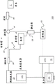
图2示出了根据本公开的实施例的使用马赫-曾德尔干涉仪系统的扫频源OCT(SS-OCT)装置。2 illustrates a swept source OCT (SS-OCT) apparatus using a Mach-Zehnder interferometer system according to an embodiment of the present disclosure.
图3示出了根据本公开的实施例的使用迈克尔逊干涉仪系统的扫频源OCT(SS-OCT)装置。3 illustrates a swept source OCT (SS-OCT) apparatus using a Michelson interferometer system according to an embodiment of the present disclosure.
图4是示出A-扫描、B-扫描和C-扫描如何与使用本公开的OCT装置形成口内要素的断层摄影图像有关的示意图。4 is a schematic diagram showing how A-scans, B-scans, and C-scans relate to the formation of tomographic images of intraoral features using the OCT device of the present disclosure.
图5是示出使用具有用于口内OCT成像的部件的宽带光源的示意图,其中光源从一个远端耦合到单模光纤中。5 is a schematic diagram illustrating the use of a broadband light source with components for intraoral OCT imaging, where the light source is coupled into a single mode fiber from one distal end.
图6是示出深度分辨口内成像装置的部件的示意图。6 is a schematic diagram showing components of a depth-resolved intraoral imaging device.
图7是示出深度分辨成像装置的部件的示意图。7 is a schematic diagram showing components of a depth-resolved imaging device.
图8是示出根据本公开的实施例的如其被定位成扫描患者的口腔的口内固定器的侧视图。8 is a side view illustrating an intraoral fixture as it is positioned to scan a patient's oral cavity, according to an embodiment of the present disclosure.
图9A和9B分别示出了口内固定器内的扫描部件的横截面图和横截面透视图。9A and 9B show a cross-sectional view and a cross-sectional perspective view, respectively, of the scanning component within the intraoral fixture.
图9C是示出根据本公开的实施例的用于口内固定器的扫描仪的部件的示意性侧视图。9C is a schematic side view showing components of a scanner for an intraoral fixture according to an embodiment of the present disclosure.
图9D是示出根据本公开的可替换实施例的用于口内固定器的扫描仪的部件的示意性侧视图。9D is a schematic side view showing components of a scanner for an intraoral fixture according to an alternative embodiment of the present disclosure.
图10A是从顶视图示出光栅扫描的细节的示意图,所述光栅扫描具有用于参考的3D正交坐标映射。Figure 10A is a schematic diagram showing details of a raster scan with a 3D orthogonal coordinate map for reference from a top view.
图10B是示出光栅扫描的一部分的顶视图的示意图。10B is a schematic diagram showing a top view of a portion of a raster scan.
图10C是示出补充图10B中提供的扫描的光栅扫描的其它部分的顶视图的示意图。Figure 10C is a schematic diagram showing a top view of other portions of a raster scan that supplements the scan provided in Figure 10B.
图11是示出根据本公开的实施例的扫描顺序的逻辑流程图。11 is a logic flow diagram illustrating a scan sequence according to an embodiment of the present disclosure.
图12A示出了用于获得由傅里叶变换处理的深度分辨信号并用于形成OCT图像的连续A-扫描的小集合。Figure 12A shows a small set of consecutive A-scans used to obtain a depth-resolved signal processed by a Fourier transform and used to form an OCT image.
图12B示出了从深度分辨扫描数据形成的重建图像。Figure 12B shows a reconstructed image formed from depth-resolved scan data.
图13A示出了使用本公开的口内系统获得的3D表面轮廓图像。13A shows a 3D surface profile image obtained using the intraoral system of the present disclosure.
图13B示出了使用本公开的口内系统生成的3D图像。Figure 13B shows a 3D image generated using the intraoral system of the present disclosure.
图13C示出了可使用本公开的口内系统获得的典型的印面剖面。Figure 13C shows a typical seal profile that can be obtained using the intraoral system of the present disclosure.
图13D示出了具有如由口内成像装置获得的牙齿的深度剖面的图像。Figure 13D shows an image with a depth profile of a tooth as obtained by an intraoral imaging device.
具体实施方式Detailed ways
下面是对示例性方法和/或装置实施例的描述,对附图进行参考,在所述附图中,在若干附图中的每一幅中相同的参考标号确定相同的结构元件。Following a description of exemplary method and/or apparatus embodiments, reference is made to the accompanying drawings in which like reference numerals identify like structural elements throughout each of the several figures.
在本公开的上下文中使用术语的情况下,术语“第一”、“第二”等不一定表示任何序数的、顺序的或优先级关系,而是仅用于更清楚地将一个步骤、元件或元件的集合与另一步骤、元件或元件的集合区分开,除非另外指明。Where terms are used in the context of this disclosure, the terms "first," "second," etc. do not necessarily denote any ordinal, sequential, or priority relationship, but are merely used to more clearly identify a step, element or set of elements to be distinguished from another step, element or set of elements, unless otherwise specified.
如本文中所使用的那样,术语“可激励的”涉及在接收到电力时并且可选地在接收到使能信号时,执行所指示的功能的设备或部件的集合。As used herein, the term "activatable" relates to a collection of devices or components that perform the indicated function upon receipt of power and optionally upon receipt of an enable signal.
在本公开的上下文中,术语“光学器件”一般用于指代用于对光射束成形和定向的透镜和其它折射、衍射和反射的部件或孔口。这种类型的单独部件被称为光学器件。In the context of this disclosure, the term "optics" is generally used to refer to lenses and other refractive, diffractive, and reflective components or apertures used to shape and direct light beams. Individual components of this type are called optics.
在本公开的上下文中,术语“查看者”、“操作者”以及“用户”被认为是等同的,并且指的是查看执业医生、技术人员或可以操作相机或扫描仪并且还可以在显示监视器上查看和操纵诸如牙齿的图像之类的图像的其它人。诸如通过点击相机或扫描仪上的按钮或通过使用计算机鼠标或通过触摸屏或键盘输入,从由查看者输入的明确命令中获得“操作者指令”或“查看者指令”。术语“主体”是指正被成像的患者的牙齿或其它部分,并且按照光学术语,可以被认为等同于对应的成像系统的“对象”。In the context of this disclosure, the terms "viewer," "operator," and "user" are considered equivalent and refer to a viewing practitioner, technician, or person who can operate a camera or scanner and also monitor the display other people viewing and manipulating images, such as images of teeth, on the device. The "operator instructions" or "viewer instructions" are obtained from explicit commands entered by the viewer, such as by clicking a button on a camera or scanner or by using a computer mouse or by entering through a touch screen or keyboard. The term "subject" refers to a tooth or other part of a patient being imaged and, in optical terms, may be considered equivalent to the "object" of the corresponding imaging system.
在本公开的上下文中,短语“进行信号通信”指示两个或更多设备和/或部件能够经由在某种类型的信号路径上行进的信号来彼此通信。信号通信可以是有线的或无线的。信号可以是通信、电力、数据或能量信号。信号路径可以包括第一设备和/或部件与第二设备和/或部件之间的物理的、电的、磁的、电磁的、光学的、有线的和/或无线的连接。信号路径还可以包括第一设备和/或部件与第二设备和/或部件之间的附加设备和/或部件。In the context of this disclosure, the phrase "in signal communication" indicates that two or more devices and/or components are capable of communicating with each other via signals traveling over some type of signal path. Signal communication can be wired or wireless. The signal can be a communication, power, data or energy signal. The signal path may include physical, electrical, magnetic, electromagnetic, optical, wired and/or wireless connections between the first device and/or component and the second device and/or component. The signal path may also include additional devices and/or components between the first device and/or component and the second device and/or component.
在本公开的上下文中,术语“相机”涉及能够从反射的可见或NIR(近红外线)光(诸如从牙齿表面和支撑结构反射的结构化光)获取反射比、2D数字图像的设备。In the context of this disclosure, the term "camera" refers to a device capable of acquiring reflectance, 2D digital images from reflected visible or NIR (Near Infrared) light, such as structured light reflected from tooth surfaces and support structures.
在本公开的上下文中,描述性短语“机械地耦合”旨在指示两个或更多部件之间的机械关联、连接、关系或链接,使得一个部件的部署影响其耦合到的部件的空间部署。对于机械耦合,两个部件不需要直接接触,而是可以通过一个或多个中间部件链接。短语“光学地耦合”指示对应的光学部件被适当地设置为在它们之间传递光学信号。In the context of the present disclosure, the descriptive phrase "mechanically coupled" is intended to indicate a mechanical association, connection, relationship or link between two or more components such that the deployment of one component affects the spatial deployment of the component to which it is coupled . For mechanical coupling, the two components do not need to be in direct contact, but can be linked through one or more intermediate components. The phrase "optically coupled" indicates that the corresponding optical components are suitably arranged to communicate optical signals therebetween.
本申请的特定示例性方法和/或装置实施例可以提供深度分辨容积成像,以用于获得表征牙齿的表面、牙龈组织和其它口内要素的信号。Certain exemplary method and/or device embodiments of the present application may provide depth-resolved volumetric imaging for use in obtaining signals characterizing the surface of teeth, gingival tissue, and other intraoral elements.
成像装置imaging device
图1示出了用于口内成像的深度分辨成像装置300的简化示意图。在中央处理单元、CPU70和信号生成逻辑74以及相关联的支持电路的控制下,探针46将激励信号引导到牙齿或其它口内要素中,如图1-3和后续附图中的样本T所示。探针46可以是手持式的或可以被握紧或以其它方式临时固定在口腔中的适当位置。探针46获得从牙齿发出的深度分辨响应信号,诸如反射和散射信号,其中响应信号对采样组织(例如,牙齿、齿龈)的深度分辨结构信息进行编码。响应信号去往检测器60,所述检测器60提供用于提取和使用编码信息的电路和支持逻辑。然后,CPU 70根据深度分辨响应信号执行牙齿表面或相关要素的表面的3D或容积图像的重建。CPU 70还可执行其它类型的处理,诸如用于识别采样组织的部分以用于改进的3D表面计算的分割处理。显示器72然后允许渲染3D表面图像内容,诸如示出重建的容积图像的单独切片。还可以根据需要执行所计算的表面数据或图像的存储和传输,所述图像示出表面数据的全部或仅一部分。Figure 1 shows a simplified schematic diagram of a depth-resolved imaging device 300 for intraoral imaging. Under the control of the central processing unit,
图2和图3的简化示意图各自示出了根据本公开的实施例的使用可编程滤波器110的扫频源OCT(SS-OCT)装置100。在每种情况下,可编程滤波器110用作提供照明源的调谐激光器50的部分。例如,对于口内OCT,激光器50可在对应于约400nm与1600nm之间的波长的频率范围(波数k)上可调谐。根据本公开的实施例,以约830nm为中心的35nm的可调谐范围的带宽可用于口内OCT。The simplified schematic diagrams of FIGS. 2 and 3 each illustrate a swept source OCT (SS-OCT)
在图2实施例中,示出了用于OCT扫描的马赫-曾德尔干涉仪系统。图3示出了用于可替换的迈克尔逊干涉仪系统的部件。对于这些实施例,可编程滤波器110提供部分激光器腔体以生成调谐激光器50输出。可变激光器50的输出通过耦合器38并到达样本臂40和参考臂42。在图2中,样本臂40信号(例如,信号T)通过循环器44并到达探针46以测量样本组织(例如,牙齿、齿列)。所采样的深度分辨信号被引导返回通过循环器44(图2)并通过耦合器58被引导至检测器60。在图3中,信号T直接去往样本臂40和参考臂42;采样信号被引导返回通过耦合器38并到达检测器60。检测器60可使用配置成消除共模噪声的一对平衡光电检测器。控制逻辑处理器(控制处理单元CPU)70与调谐激光器50及其可编程滤波器110以及与检测器60进行信号通信,并且获得以及处理来自检测器60的输出。还如图1中所示,CPU 70与显示器72进行信号通信以用于命令输入和用于OCT结果显示,诸如从各种角度和剖面或切片渲染3D图像内容。然而,常规的附加操作者/命令输入设备可以与示例性深度分辨成像装置300或示例性装置100一起使用。In the Figure 2 embodiment, a Mach-Zehnder interferometer system for OCT scanning is shown. Figure 3 shows components for an alternative Michelson interferometer system. For these embodiments, the
图4的示意图示出了可用于使用本公开的OCT装置形成口内要素的断层摄影图像的扫描序列。图4中所示出的序列总结了如何生成单个B-扫描图像。光栅扫描仪逐点扫描所选择的光序列作为样本牙齿上的照明。如图4中所示出的周期性驱动信号92用于驱动光栅扫描仪反射镜以控制跨样本的每一行延伸的横向扫描或B-扫描,示出为沿水平方向延伸的离散点82。在沿着B-扫描的线或行的多个点82中的每一个处,使用所选择的波长带的连续部分生成A-扫描或深度扫描,从而沿z-轴方向获取数据。图4示出了用于使用光栅扫描仪生成简明的升序序列的驱动信号92,所述光栅扫描仪具有通过波长带的激光器的对应调谐。向后扫描信号93(驱动信号92的一部分)简单地将扫描反射镜恢复回到其用于下一线的开始位置;在向后扫描信号93期间不获得数据。4 is a schematic diagram illustrating a scan sequence that may be used to form tomographic images of intraoral features using the OCT device of the present disclosure. The sequence shown in Figure 4 summarizes how a single B-scan image is generated. The selected light sequence is scanned point by point with the raster scanner as illumination on the sample tooth. A periodic drive signal 92 as shown in Figure 4 is used to drive the raster scanner mirror to control a lateral scan or B-scan extending across each row of the sample, shown as
应当注意的是,B-扫描驱动信号92驱动用于OCT探针46(图2、3)的光栅扫描仪的可致动扫描机构,诸如检流计或微机电反射镜。在每个递增扫描仪位置处,沿着B-扫描、A-扫描的行的每个点82被获得为1D数据的类型,从而沿着延伸到牙齿中的单条线提供深度分辨数据。为了获取具有频谱OCT的A-扫描数据,调谐激光器或其它可编程光源扫过频谱序列。因此,在其中可编程滤波器使得光源扫过30nm波长范围的实施例中,在沿着B-扫描路径的每个点82处执行用于生成照明的此序列。如图4所示,A-扫描获取的集合在每个点82处执行,即在扫描反射镜的每个位置处执行。作为示例,可以存在2048个测量,以用于在每个位置82处生成A-扫描。It should be noted that the B-scan drive signal 92 drives an actuatable scanning mechanism, such as a galvanometer or a microelectromechanical mirror, for the raster scanner of the OCT probe 46 (FIGS. 2, 3). At each incremental scanner position, each
图4示意性地示出了在每个A-扫描期间获取的信息。在每个点82的时间间隔内获取被示出具有移除的DC信号内容的干涉信号88,其中该信号是用于扫过所需的时间间隔的函数(其与扫频源的波长具有一一对应关系),其中所获取的信号指示通过组合来自干涉仪(图2、3)的参考和反馈(或样本)臂的光而生成的频谱干涉条纹。傅里叶变换为每个A-扫描生成变换TF。在图4中作为示例示出了对应于A-扫描的一个变换信号。Figure 4 schematically shows the information acquired during each A-scan. An interference signal 88, shown with removed DC signal content as a function of the time interval required for the sweep (which is a function of the wavelength of the swept source, is acquired during the time interval at each point 82) a correspondence), where the acquired signal is indicative of the spectral interference fringes generated by combining light from the reference and feedback (or sample) arms of the interferometer (Figs. 2, 3). The Fourier transform generates a transform TF for each A-scan. A transformed signal corresponding to an A-scan is shown as an example in FIG. 4 .
根据以上描述,可以理解的是,在单个B-扫描序列上获取了大量的数据。为了有效地处理该数据,使用快速傅里叶变换(FFT),将基于频谱的信号数据变换成对应的基于空间的数据,从该基于空间的数据可以更容易地生成图像内容。From the above description, it will be appreciated that a large amount of data is acquired on a single B-scan sequence. To efficiently process this data, the spectral-based signal data is transformed into corresponding spatial-based data, from which image content can be more easily generated, using a Fast Fourier Transform (FFT).
在傅里叶域OCT中,A扫描对应于生成深度分辨OCT信号的(z-轴)线的一条频谱获取线。B扫描数据生成2D OCT图像作为沿着对应扫描线的行R。光栅扫描用于通过沿C-扫描方向递增光栅扫描仪获取来获得多个B-扫描数据。In Fourier-domain OCT, the A-scan corresponds to one spectral acquisition line that generates the (z-axis) line of the depth-resolved OCT signal. The B-scan data generates a 2D OCT image as a row R along the corresponding scan line. Raster scanning is used to obtain multiple B-scan data by incremental raster scanner acquisition along the C-scan direction.
本公开的实施例使用低相干光源,诸如例如SLD(超辐射发光二极管),其具有适合于多个牙齿的受控连续扫描的口内固定器和扫描模式。扫描模式特别适配成促进自动图像捕获和处理,以准确地表征具有深度分辨OCT成像的牙齿结构。Embodiments of the present disclosure use a low coherence light source, such as, for example, an SLD (Super Luminous Light Emitting Diode) with an intraoral fixture and scan mode suitable for controlled continuous scanning of multiple teeth. The scan mode is specially adapted to facilitate automatic image capture and processing to accurately characterize tooth structure with depth-resolved OCT imaging.
图5的示意图示出了根据本公开的实施例的从用于口内OCT成像的一个远端耦合到2X2单模光纤22中的宽带光源20的使用。在参考图2和图3概述的基本模式之后,将宽带光分成参考光和样本光(例如,分成样本T)。来自样本臂40的样本光输出被准直,然后由诸如MEMS扫描仪、检流计扫描仪或其它扫描仪装置的扫描反射镜24操纵。该被扫描的光被聚焦到样本S的表面上和下面的组织上并由所述组织散射。来自样本S的反向散射光经由公共光学扫描路径被耦合到样本臂光纤中。参考光从参考反射镜26向后反射。来自参考臂42的参考光与2x2光纤耦合器38处的反向散射样本光干涉。干涉光被传送到示出为检测器30的定制频谱仪中。一条频谱的线被获取、处理、变换成对应于样本S处的每个扫描点的一条深度分辨信号的线。5 is a schematic diagram illustrating the use of a
扫描反射镜24以相对慢的速度(例如,25fps(每秒帧数))将1D光栅扫描引导到样本S。对于口内成像,对于每个扫描线,扫描宽度可以在10-15mm之间。针对1D扫描线的每个扫描点同步地获取1D干涉频谱。例如,以用于维持25fps的标称25000行/秒获取速度获取1000条频谱线。这给出了10-15μm范围内的扫描数字分辨率。横向光学分辨率由聚焦的扫描机身中部确定。深度分辨率与光源20的带宽成反比。因此,来自光源20的光射束越宽,深度分辨率越高。作为示例,深度分辨率可以是5.6μm,其具有中心波长800nm和50nm带宽光源20。
继续图5的描述,可提供引导光源138以用于帮助提供患者的口腔内的照明以便改进扫描部件的定位。Continuing the description of FIG. 5, a guide
图6是示出深度分辨成像装置200的部件的示意图。在成像引擎52中,光源20将光引导通过2x2光纤耦合器38,所述耦合器将光引导到参考臂28以及引导到样本臂40,所述样本臂40光学地耦合到口内固定器62。来自固定器62的经调制光然后由耦合器38按某路线发送回到检测器60、干涉仪的装置。处理器80(诸如计算机或专用控制逻辑处理器)例如然后提供用于装置200的功能的控制和操作逻辑。显示器34与处理器80进行信号通信,以用于显示成像结果。FIG. 6 is a schematic diagram illustrating the components of the depth-resolved
图7的示意图示出了具有口内固定器62的深度分辨成像装置200的部件,所述口内固定器62具有可用于在不使用时安置设备的固定件64。当口内固定器62不被使用时,固定件64可提供电力和/或保护。可以提供诸如操作者控制开关48的控制用于启动或暂停扫描序列,如后续更详细地描述的那样。在图7中所示出的示例性实施例中,成像引擎52包括用于控制成像装置200功能的集成处理器(未示出)。例如,成像引擎52可以包括图6中所示出的任何或所有部件。成像引擎52通过线缆68连接到口内固定器62,线缆68可包括用于电信号和电力的接线和样本臂光纤40。The schematic diagram of FIG. 7 shows the components of a depth-resolved
图8是根据本公开的实施例的示出口内固定器62在其被定位用于扫描患者36的口腔内的牙齿时的侧视图。患者36通过咬合在设备上、将固定器62握紧在适当位置、在扫描期间夹在颌内来保持固定器62。控制开关48允许患者在没有技术人员或执业医生的辅助的情况下启动用于自扫描的扫描序列。可选的相机94安装在固定器62内,以用于提供示出扫描区域的至少一些部分的预览图像。根据本公开的实施例,预览相机94显示指示固定器62在显示器34上的位置的反射性图像(图6)。图像可以是例如两种或更多种颜色(多色的)或单色的。该显示器允许查看者或其它技术人员或执业医生确定固定器62的进一步调整或重新定位是否将对后续的OCT扫描有用。在放置用于扫描牙齿的齿弓的部分子集的固定器62是有用的情况下,诸如在要扫描一个或多个牙齿的情况下,该特征可以是特别有用的。FIG. 8 is a side view showing the
根据本公开的实施例,固定器62具有扫描定向,使得扫描装置可定位成面向上牙齿的齿弓或下牙齿的齿弓。此配置使得固定器62能够被反转用于分别扫描患者的齿列的每一半。According to an embodiment of the present disclosure, the
可替换地,固定器62可以具有内轨道,所述内轨道具有用于沿着用于患者的合适轨道推动扫描仪130的外部电机。还可以提供对不同齿弓尺寸的调整。Alternatively, the
图9A和9B分别示出了用于口内固定器62的各种实施例的扫描仪部件的横截面图和横截面透视图。一个或多个扫描仪130各自沿着固定器62内的轨道132被引导,以便紧靠牙齿122、124和相关的口内要素执行OCT光模式的B-扫描照射。轨道132可以具有用于沿着弯曲路径引导(一个或多个)扫描仪的任何合适的布置。FIGS. 9A and 9B show a cross-sectional view and a cross-sectional perspective view, respectively, of scanner components for various embodiments of the
作为示例,在图9A所示出的实施例中提供了五个扫描仪的堆积或集合。扫描仪可被暴露或在透明盖后面。扫描仪130的完整集合沿着通道134内的轨道132被推动,相对于弯曲轨道132正交地扫描,以便提供x-扫描(C-扫描)移动。扫描仪130a和130b扫描牙齿的舌侧表面;扫描仪130d和130e扫描脸颊侧表面。一个或多个扫描仪130c扫描牙齿的咀嚼表面的中心部分。通常,相邻表面的扫描区具有一些重叠。如果扫描仪130a、130b、130d和130e具有足够大的视场,则其组合的扫描区可以有可能完全覆盖齿咬合表面,而不需要附加的扫描仪130c。可以提供分离的扫描仪用于使用相同的轨道132或使用多个轨道来扫描上颌骨和下颌骨牙齿结构。对于图9A的堆积布置,例如,上颌骨齿弓和下颌骨齿弓两者可在单次通过中被扫描。扫描仪130各自通过光纤光学地耦合到样本臂40(图5、6),当扫描沿着轨道132前进时,所述光纤能够弯曲以跟随扫描路径曲率。机械耦合到致动器沿着轨道132提供所需的运动。来自多个扫描仪130的单独信号可以由检测器60以时分复用的方式检测。As an example, a stack or set of five scanners is provided in the embodiment shown in Figure 9A. The scanner can be exposed or behind a transparent cover. The complete set of
图9B示出能够一次沿着轨道132的一个部分扫描的单个扫描仪130。扫描仪130的多次通过可用于不同牙齿表面的深度分辨表征。FIG. 9B shows a
可以使用各种类型的扫描仪130设计。图9C是示出根据本公开的实施例的用于口内固定器的扫描仪130的部件的示意性侧视图。这里,扫描仪130使用微机电系统(MEMS)设备96,所述设备提供可快速移动的反射性表面以用于偏转来自单模光纤22的扫描光能量,来朝向牙齿或其它主体解剖结构外提供具有沿一个方向的照明的B-扫描,并且沿相对方向反馈回到干涉仪或其它检测器以用于分析。微小的梯度折射率透镜或GRIN透镜98或其它类型的光学器件用于调节用于扫描仪能量的光路径。例如,到和来自光纤22的光到透镜98的光学耦合可以通过间隔件160或使用光学粘合剂。Various types of
图9D是示出根据本公开的可替换实施例的用于口内固定器的扫描仪130的部件的示意性侧视图。GRIN透镜98和耦合部件类似于图9C的那些。扫描仪照明是通过使用驱动反射性表面164以影响B-扫描的电机162的偏转来提供的。9D is a schematic side view showing components of a
参照图10A、10B和10C,扫描仪130的每个布置跟随轨道132以提供一个或多个扫描路径。轨道132弯曲以跟随颌内的牙齿32的弯曲布置。图9A中所示出的固定器62布置提供了多个扫描仪,从而允许如图10A中所示出的单通扫描布置,其可以为上颌骨齿弓和下颌骨齿弓两者提供深度分辨成像。10A, 10B and 10C, each arrangement of
如图9B中所示,可以使用图10B和图10C扫描路径,其中在固定器62内提供单个扫描仪130。扫描仪可以被定向成使得其视场覆盖平滑表面和咬合表面两者。在第一次通过中,可以扫描脸颊侧表面和齿咬合表面。然后,在扫描仪130沿定向翻转(例如,手动地或使用分节器电机)并且然后在相对方向上沿着路径132被推动的情况下,可以扫描舌侧表面和齿咬合表面。As shown in FIG. 9B , the scan path of FIGS. 10B and 10C may be used, wherein a
根据本公开的可替换实施例,固定器62配置成一次仅扫描上颌骨齿弓或仅扫描下颌骨齿弓。参考图8,患者扫描上齿弓,其中固定器62处于执行图10A-10C中所示出的适当扫描的第一定向。然后,患者反转固定器62的定向,以在后续扫描中扫描下颌骨齿弓。According to alternative embodiments of the present disclosure, the
使用图10A到10C的扫描布置,每一B扫描使用所示出的坐标指定在y-z平面中产生2D深度剖面。B扫描定向是相对于轴y的,其具有扫描路径,并且针对使用图10B和10C的序列,具有返回路径。到图10A-10C的顶视图中的页面中,并且在左侧的放大的侧视图E中向下的轴z是深度定向。第三尺寸x扫描通过沿着轨道132的弯曲路径推动扫描仪装置120来实现。致动器140沿着弯曲路径向前推动扫描装置120。牙齿被编号为1-16以对应于下口腔的常规牙科牙齿编号。牙齿的全3D图像可以通过沿所示出的x方向将如沿着弯曲路径获取的2D图像缝合在一起而形成。Using the scan arrangement of Figures 10A-10C, each B-scan produces a 2D depth profile in the y-z plane using the coordinate assignments shown. The B-scan orientation is relative to axis y, which has a scan path and, for the sequence using Figures 10B and 10C, a return path. The down axis z into the page in the top view of Figures 10A-10C and in the enlarged side view E on the left is the depth orientation. The third dimension x-scan is achieved by pushing the scanner device 120 along the curved path of the
许多类型的常规驱动器(诸如电机、机电机构或其它设备)中的任一种可用作致动器140,其机械地耦合到扫描仪130,以用于沿着轨道132提供规定的平移(例如,线性或非线性)。根据本公开的实施例,致动器140可以是使用绳索或绳沿着轨道132推动(一个或多个)扫描仪130的电机。可以提供滑轮机构以用于沿着弯曲轨道132提供(一个或多个)扫描仪130的该C-扫描或x-轴运动。Any of a number of types of conventional drives (such as motors, electromechanical mechanisms, or other devices) may be used as actuator 140, which is mechanically coupled to
图7-10C的示例性实施例提供了固定器62,其一旦被安装到位并且诸如通过患者的咬合被保持在适当的位置,就可用于一次扫描多个牙齿、完整的上牙齿的齿弓或下牙齿的齿弓、或者甚至(在给定适当的图10A的固定器62设计的情况下)扫描患者的所有上牙齿或所有下牙齿。如前所述,为了扫描全口腔,患者可以首先插入咬合部分66以扫描下牙齿,然后反转固定器62的垂直定向以便扫描上牙齿。可替换地,上齿弓可以首先被扫描,随后是下齿弓。另外,可以使用来自处理器或计算机的命令来控制设备,以如由执业医生所需要的那样仅扫描完整牙齿的齿弓的一部分或选定部分。The exemplary embodiment of FIGS. 7-10C provides a
根据本公开的实施例,对于包括面部、齿咬合和舌侧扫描的牙齿的集合,使用大约14cm的平均成人牙齿长度计算,以25000行/秒的获取速度下500行/B扫描的30μm的x,y扫描分辨率,每次扫描花费大约93s。y扫描长度在10-15mm范围内。如果使用三次通过,则使用这些值的完整的下齿弓扫描花费近似180秒=3分钟。According to an embodiment of the present disclosure, for a set of teeth including facial, occlusal and lingual scans, calculated using an average adult tooth length of approximately 14 cm, x 30 μm of 500 lines/B scan at an acquisition speed of 25,000 lines/sec , y scan resolution, each scan takes about 93s. The y scan length is in the range of 10-15mm. If three passes are used, a complete lower dental arch scan using these values takes approximately 180 seconds = 3 minutes.
应当注意的是,不同大小的固定器62可用于不同口腔大小的患者,从而允许用于具有不同构造的患者的合适的扫描布置。可替换地,可使用铰接布置来提供可调整的固定器,例如以使固定器与特定患者的齿弓形状相适合。控制软件可以被编程为将扫描限制到非线性、弯曲或弓形扫描路径的有限部分。示例性固定器62的附加特征可用于容易地将固定器62相对于患者的牙齿或齿弓定位。在一些示例性实施例中,固定器62可以可移除地固定到患者的上颌或下颌或定位在患者的上颌或下颌以用于深度分辨图像扫描,使得患者不需要在扫描期间向下咬在固定器62上。在一个示例性实施例中,固定器62可通过抵靠上颌或下颌的内侧或外侧的多个(例如,相对的)侧推动的张力或弹性特性而保持在适当位置。在一个示例性实施例中,固定器62可由未被扫描的牙齿、颌或齿列的部分保持在适当位置。It should be noted that different
扫描顺序scan order
图11是示出根据本公开的实施例的扫描顺序的逻辑流程图。在设置步骤S100中,患者、技术人员或执业医生将口内扫描固定器62插入患者的口腔中。患者可向下咬合以将固定器62保持在适当位置。在启动步骤S110中,患者或技术人员/执业医生对固定器62上电以用于扫描。固定器62扫描仪部件可以被复位到用于扫描的开始位置。在扫描步骤S120中,随着扫描仪行进而执行扫描,B-扫描模式扫描使得扫描仪反射镜沿着轨道132移动,如之前参考图10所示。在数据获取步骤S130中,获取来自口内固定器62的频谱图像数据并将其传输到处理器60(图6)。然后,在表面数据被获得并被预处理时,显示步骤S140显示来自最近获取的深度分辨牙齿图像的扫描的表面数据。在判定步骤S150中,系统逻辑确定由固定器进行的全扫描是否完成。直到扫描完成,连续执行步骤S120、S130和S140,获取和更新扫描的图像数据。然后,容积显示、存储、传输步骤S160形成用于显示、存储或传输的3D表面容积。11 is a logic flow diagram illustrating a scan sequence according to an embodiment of the present disclosure. In setting step S100, the patient, technician or medical practitioner inserts the
图像处理Image Processing
图12A示出了用于获得由傅里叶变换(TF)处理并用于形成OCT图像的深度分辨信号的连续A-扫描的小集合。数据图12B示出了从深度分辨扫描数据形成的重建图像。Figure 12A shows a small set of consecutive A-scans used to obtain depth-resolved signals processed by Fourier Transform (TF) and used to form OCT images. Data Figure 12B shows a reconstructed image formed from depth-resolved scan data.
图13A示出了根据本申请的特定示例性方法和/或装置实施例获得的3D表面轮廓图像210。图13B示出了从扫描数据重建的3D图像214。图13C示出了可以从扫描数据生成的典型的印面剖面212。图13D示出了具有如由口内成像装置获得的牙齿深度剖面的B-扫描图像216。FIG. 13A illustrates a 3D
与本文中的示例性实施例一致,计算机程序可使用对从电子存储器存取的图像数据执行的所存储指令。如由图像处理领域的技术人员可以理解的那样,用于在本申请的示例性实施例中操作成像系统和探针以及获取图像数据的计算机程序可以由诸如个人计算机或工作站之类的操作为如本文中描述的CPU 70的适合的通用计算机系统利用。然而,许多其它类型的计算机系统可用于执行本发明的计算机程序,例如包括联网处理器的布置。用于执行示例性方法实施例的计算机程序可以存储在计算机可读存储介质中。该介质可以包括例如;磁性存储介质,诸如例如硬盘驱动器或可移动设备或磁带之类的磁盘;光学存储介质,诸如光盘、光带或机器可读光学编码;固态电子存储设备,诸如随机存取存储器(RAM)或只读存储器(ROM);或用于存储计算机程序的任何其它物理设备或介质。用于执行示例性方法实施例的计算机程序也可以存储在通过因特网或其它网络或通信介质连接到图像处理器的计算机可读存储介质上。本领域技术人员将进一步容易地认识到的是,这样的计算机程序产品的等同物也可以按照硬件来构造。Consistent with the exemplary embodiments herein, a computer program may use stored instructions that execute on image data accessed from electronic memory. As can be appreciated by those skilled in the art of image processing, the computer programs for operating the imaging system and probe and acquiring image data in the exemplary embodiments of the present application may be operated by, for example, a personal computer or workstation as Suitable general-purpose computer system utilization of the
应当注意的是,与在本申请的上下文中的“计算机可访问存储器”等同的术语“存储器”可以指用于存储和操作在图像数据上并且可以访问计算机系统的任何类型的临时的或更持久的数据存储工作空间,例如包括数据库。存储器可以是非易失性的,例如使用诸如磁性或光学存储器的长期存储介质。可替换地,存储器可以具有更易失性本质,使用电子电路,诸如随机存取存储器(RAM),其由微处理器或其它控制逻辑处理器设备用作临时缓冲器或工作空间。例如,显示数据典型地被存储在与显示设备直接相关联的临时存储缓冲器中,并且根据需要被周期性地刷新以便提供所显示的数据。该临时存储缓冲器也被认为是一种类型的存储器,因为该术语在本申请中使用。存储器还用作用于执行和存储计算和其它处理的中间结果和最终结果的数据工作空间。计算机可访问的存储器可以是易失性、非易失性、或易失性和非易失性类型的混合组合。It should be noted that the term "memory", which is equivalent to "computer-accessible memory" in the context of this application, may refer to any type of temporary or persistent storage and operation on image data and access to a computer system. Data storage workspaces, including databases, for example. The memory may be non-volatile, for example using long-term storage media such as magnetic or optical memory. Alternatively, the memory may be of a more volatile nature, using electronic circuitry, such as random access memory (RAM), which is used by a microprocessor or other control logic processor device as a temporary buffer or work space. For example, display data is typically stored in a temporary storage buffer directly associated with the display device, and is periodically refreshed as needed to provide the displayed data. The temporary storage buffer is also considered a type of memory, as that term is used in this application. Memory also serves as a data workspace for performing and storing intermediate and final results of computations and other processing. Computer-accessible memory can be volatile, nonvolatile, or a mixed combination of volatile and nonvolatile types.
将理解的是,本申请的计算机程序产品可以利用众所周知的各种图像操纵算法和处理。将进一步理解的是,本申请的计算机程序产品示例性实施例可以体现在本文中未具体示出或描述的可用于实施的算法和处理。这样的算法和处理可包括图像处理领域的普通技术内的常规利用。这样的算法和系统的附加方面,以及用于产生和以其它方式处理图像或与本申请的计算机程序产品示例性实施例协作的硬件和/或软件在本文中没有具体示出或描述,并且可以从本领域中已知的这样的算法、系统、硬件、部件和元件中选择。It will be appreciated that the computer program product of the present application may utilize various well-known image manipulation algorithms and processes. It will be further understood that the exemplary embodiments of the computer program product of the present application may embody algorithms and processes that may be implemented for implementation not specifically shown or described herein. Such algorithms and processing may include conventional utilization within ordinary skill in the art of image processing. Additional aspects of such algorithms and systems, as well as hardware and/or software for generating and otherwise processing images or in cooperation with exemplary embodiments of the computer program product of the present application, are not specifically shown or described herein, and may Select from such algorithms, systems, hardware, components and elements known in the art.
本申请的特定示例性方法和/或装置实施例可以提供深度分辨容积成像以表征牙齿、牙龈组织和其它口内要素的表面。根据本申请的示例性实施例可以包括本文中(单独地或组合地)描述的各种特征。Certain exemplary method and/or device embodiments of the present application may provide depth-resolved volumetric imaging to characterize the surfaces of teeth, gingival tissue, and other intraoral elements. Exemplary embodiments in accordance with the present application may include various features described herein (either alone or in combination).
虽然已经关于一个或多个实施方式说明了本发明,但是在不背离所附权利要求的精神和范围的情况下,可以对所说明的示例进行替换和/或修改。另外,虽然本发明的特定特征可能已经相对于若干实施方式/实施例中的仅一者而公开,但这样的特征可与其它实施方式/实施例的一个或多个其它特征组合,如可期望且有利地用于任何给定或特定功能。术语“…中的至少一个”用于表示列出的项目中的一个或多个可以被选择。术语“约”指示列出的值可以在一定程度上更改,只要该更改不会导致过程或结构与所说明实施例不一致。最后,“示例性”指示描述被用作示例,而不是暗示它是理想的。考虑到本文中公开的本发明的说明书和实践,本发明的其它实施例对于本领域技术人员将是显而易见的。说明书和示例旨在仅被认为是示例性的,其中本发明的真实范围和精神由至少以下权利要求指示。While the invention has been described with respect to one or more embodiments, substitutions and/or modifications may be made to the described examples without departing from the spirit and scope of the appended claims. Additionally, although a particular feature of the invention may have been disclosed with respect to only one of several implementations/embodiments, such features may be combined with one or more other features of other implementations/embodiments, as may be desired and advantageously for any given or specific function. The term "at least one of" is used to indicate that one or more of the listed items may be selected. The term "about" indicates that the listed value may be modified to the extent that the modification does not result in a process or structure inconsistent with the described embodiments. Finally, "exemplary" indicates that the description is used as an example, rather than implying that it is ideal. Other embodiments of the invention will be apparent to those skilled in the art from consideration of the specification and practice of the invention disclosed herein. The specification and examples are intended to be regarded as exemplary only, with the true scope and spirit of the invention being indicated by at least the following claims.
Claims (17)
Applications Claiming Priority (1)
| Application Number | Priority Date | Filing Date | Title |
|---|---|---|---|
| PCT/US2016/046224 WO2018031003A1 (en) | 2016-08-10 | 2016-08-10 | Automatic intraoral 3d scanner with low coherence ranging |
Publications (1)
| Publication Number | Publication Date |
|---|---|
| CN110650672A true CN110650672A (en) | 2020-01-03 |
Family
ID=56801793
Family Applications (1)
| Application Number | Title | Priority Date | Filing Date |
|---|---|---|---|
| CN201680088229.2A Pending CN110650672A (en) | 2016-08-10 | 2016-08-10 | Automated Intraoral 3D Scanner Using Low Coherence Ranging |
Country Status (6)
| Country | Link |
|---|---|
| US (1) | US10888231B2 (en) |
| EP (1) | EP3496591A1 (en) |
| JP (1) | JP2019524327A (en) |
| KR (1) | KR20190037253A (en) |
| CN (1) | CN110650672A (en) |
| WO (1) | WO2018031003A1 (en) |
Cited By (1)
| Publication number | Priority date | Publication date | Assignee | Title |
|---|---|---|---|---|
| CN113648094A (en) * | 2021-08-11 | 2021-11-16 | 苏州喆安医疗科技有限公司 | Split type oral cavity digital impression instrument |
Families Citing this family (10)
| Publication number | Priority date | Publication date | Assignee | Title |
|---|---|---|---|---|
| US10390913B2 (en) | 2018-01-26 | 2019-08-27 | Align Technology, Inc. | Diagnostic intraoral scanning |
| US10507087B2 (en) * | 2016-07-27 | 2019-12-17 | Align Technology, Inc. | Methods and apparatuses for forming a three-dimensional volumetric model of a subject's teeth |
| JP6786424B2 (en) * | 2017-03-13 | 2020-11-18 | 株式会社モリタ製作所 | 3D scanner |
| US20210022593A1 (en) * | 2019-07-24 | 2021-01-28 | United States Of America As Rep By Sec Of The Navy | Photoplethysmography Imaging (PPGI)-Based Pulp Vitality Test |
| CN110490019A (en) * | 2019-08-26 | 2019-11-22 | 顺德职业技术学院 | One kind being used for computer data acquiring device |
| JP7131861B1 (en) | 2021-06-09 | 2022-09-06 | 株式会社吉田製作所 | OCT apparatus controller and OCT apparatus control program |
| DE102023120051A1 (en) * | 2023-07-27 | 2025-01-30 | epitome GmbH | device for performing intraoral scans |
| DE102023120250A1 (en) * | 2023-07-31 | 2025-02-06 | epitome GmbH | device for performing intraoral scans |
| DE102023123458A1 (en) * | 2023-08-31 | 2025-03-06 | epitome GmbH | device for performing intraoral scans |
| WO2025129316A1 (en) * | 2023-12-18 | 2025-06-26 | Hyperspectral Intelligence Inc. | Non-contact handheld continuous point reflectance spectrometry scanner and methods therefor |
Citations (9)
| Publication number | Priority date | Publication date | Assignee | Title |
|---|---|---|---|---|
| US20020055082A1 (en) * | 2000-10-25 | 2002-05-09 | Duane Durbin | Method and system for imaging and modeling a three dimensional structure |
| JP2008058138A (en) * | 2006-08-31 | 2008-03-13 | National Center For Geriatrics & Gerontology | Dental optical tomographic image display system |
| US20080062429A1 (en) * | 2006-09-12 | 2008-03-13 | Rongguang Liang | Low coherence dental oct imaging |
| US20080118886A1 (en) * | 2006-11-21 | 2008-05-22 | Rongguang Liang | Apparatus for dental oct imaging |
| CN101589968A (en) * | 2009-06-17 | 2009-12-02 | 徐宝华 | Make the method for orthodontic bracket |
| CN103596521A (en) * | 2011-04-07 | 2014-02-19 | 3形状股份有限公司 | 3D system and method for guiding objects |
| US20140272773A1 (en) * | 2013-03-14 | 2014-09-18 | X-Nav Technologies, LLC | Image Guided Navigation System |
| US20150072313A1 (en) * | 2012-05-07 | 2015-03-12 | Sirona Dental System Gmbh | Method for measuring a dental situation |
| WO2015188286A1 (en) * | 2014-06-11 | 2015-12-17 | Quarz Partners Ag | Measuring apparatus and method for three-dimensional measurement of an oral cavity |
Family Cites Families (8)
| Publication number | Priority date | Publication date | Assignee | Title |
|---|---|---|---|---|
| JPH0910241A (en) * | 1995-06-30 | 1997-01-14 | Matsushita Electric Ind Co Ltd | Tooth mold molding method and manufacturing apparatus therefor |
| US6386867B1 (en) * | 2000-11-30 | 2002-05-14 | Duane Milford Durbin | Method and system for imaging and modeling dental structures |
| JP2004344260A (en) * | 2003-05-20 | 2004-12-09 | J Morita Tokyo Mfg Corp | Dental optical diagnostic equipment |
| JP4822454B2 (en) * | 2005-11-22 | 2011-11-24 | 株式会社松風 | Dental optical coherence tomography system |
| FR2960962B1 (en) * | 2010-06-08 | 2014-05-09 | Francois Duret | DEVICE FOR THREE DIMENSIONAL AND TEMPORAL MEASUREMENTS BY COLOR OPTICAL FOOTPRINT. |
| EP2875771A4 (en) * | 2012-07-19 | 2016-04-20 | Nat Ct Geriatrics & Gerontology | MEASURING / DISPLAYING METHOD AND MEASURING / DISPLAY DEVICE FOR DENTAL PLATE, GENCIVE AND ALVEOLAR BONE |
| CN104853692A (en) | 2012-11-28 | 2015-08-19 | 阿波罗口腔扫描仪有限责任公司 | Dental scanning device |
| DE102014205784B4 (en) | 2014-03-27 | 2024-01-18 | Sirona Dental Systems Gmbh | Scanning device |
-
2016
- 2016-08-10 JP JP2019507831A patent/JP2019524327A/en active Pending
- 2016-08-10 CN CN201680088229.2A patent/CN110650672A/en active Pending
- 2016-08-10 EP EP16757405.2A patent/EP3496591A1/en not_active Withdrawn
- 2016-08-10 US US16/324,824 patent/US10888231B2/en not_active Expired - Fee Related
- 2016-08-10 KR KR1020197003759A patent/KR20190037253A/en not_active Withdrawn
- 2016-08-10 WO PCT/US2016/046224 patent/WO2018031003A1/en not_active Ceased
Patent Citations (10)
| Publication number | Priority date | Publication date | Assignee | Title |
|---|---|---|---|---|
| US20020055082A1 (en) * | 2000-10-25 | 2002-05-09 | Duane Durbin | Method and system for imaging and modeling a three dimensional structure |
| JP2008058138A (en) * | 2006-08-31 | 2008-03-13 | National Center For Geriatrics & Gerontology | Dental optical tomographic image display system |
| US20080062429A1 (en) * | 2006-09-12 | 2008-03-13 | Rongguang Liang | Low coherence dental oct imaging |
| US20080118886A1 (en) * | 2006-11-21 | 2008-05-22 | Rongguang Liang | Apparatus for dental oct imaging |
| CN101563021A (en) * | 2006-11-21 | 2009-10-21 | 卡尔斯特里姆保健公司 | Apparatus for optical coherence tomography imaging of teeth |
| CN101589968A (en) * | 2009-06-17 | 2009-12-02 | 徐宝华 | Make the method for orthodontic bracket |
| CN103596521A (en) * | 2011-04-07 | 2014-02-19 | 3形状股份有限公司 | 3D system and method for guiding objects |
| US20150072313A1 (en) * | 2012-05-07 | 2015-03-12 | Sirona Dental System Gmbh | Method for measuring a dental situation |
| US20140272773A1 (en) * | 2013-03-14 | 2014-09-18 | X-Nav Technologies, LLC | Image Guided Navigation System |
| WO2015188286A1 (en) * | 2014-06-11 | 2015-12-17 | Quarz Partners Ag | Measuring apparatus and method for three-dimensional measurement of an oral cavity |
Cited By (2)
| Publication number | Priority date | Publication date | Assignee | Title |
|---|---|---|---|---|
| CN113648094A (en) * | 2021-08-11 | 2021-11-16 | 苏州喆安医疗科技有限公司 | Split type oral cavity digital impression instrument |
| CN113648094B (en) * | 2021-08-11 | 2023-10-27 | 苏州喆安医疗科技有限公司 | Split type oral cavity digital impression instrument |
Also Published As
| Publication number | Publication date |
|---|---|
| EP3496591A1 (en) | 2019-06-19 |
| JP2019524327A (en) | 2019-09-05 |
| KR20190037253A (en) | 2019-04-05 |
| US20190223732A1 (en) | 2019-07-25 |
| WO2018031003A1 (en) | 2018-02-15 |
| US10888231B2 (en) | 2021-01-12 |
Similar Documents
| Publication | Publication Date | Title |
|---|---|---|
| US10888231B2 (en) | Automatic intraoral 3D scanner with low coherence ranging | |
| EP3645964B1 (en) | Surface mapping using an intraoral scanner with penetrating capabilities | |
| JP4822454B2 (en) | Dental optical coherence tomography system | |
| US12465464B2 (en) | Intraoral 3D scanning with automatic charting | |
| US11172824B2 (en) | Hybrid OCT and surface contour dental imaging | |
| US20080118886A1 (en) | Apparatus for dental oct imaging | |
| KR20100111226A (en) | Dental diagnostic system by means of optical coherence tomography | |
| US10966803B2 (en) | Intraoral 3D scanner with fluid segmentation | |
| US20240277229A1 (en) | Intraoral scanner using common-path optical coherence tomography | |
| US20240197181A1 (en) | Intraoral optical coherence tomography scanner with optical fiber adapter | |
| US20190261861A1 (en) | Method and apparatus for ear impression and ent imaging | |
| US20250031970A1 (en) | Intraoral oct apparatus |
Legal Events
| Date | Code | Title | Description |
|---|---|---|---|
| PB01 | Publication | ||
| PB01 | Publication | ||
| SE01 | Entry into force of request for substantive examination | ||
| SE01 | Entry into force of request for substantive examination | ||
| TA01 | Transfer of patent application right | ||
| TA01 | Transfer of patent application right |
Effective date of registration: 20220809 Address after: State of Georgia, US Applicant after: Ruike dental Co.,Ltd. Address before: London Applicant before: CARESTREAM HEALTH, Inc. |
|
| TA01 | Transfer of patent application right | ||
| TA01 | Transfer of patent application right |
Effective date of registration: 20220921 Address after: Pennsylvania, America Applicant after: IMAGING SCIENCES INTERNATIONAL LLC Address before: State of Georgia, US Applicant before: Ruike dental Co.,Ltd. |
|
| RJ01 | Rejection of invention patent application after publication | ||
| RJ01 | Rejection of invention patent application after publication |
Application publication date: 20200103 |