According to 35u.s.c. § 119, the present application claims priority to U.S. provisional application serial No. 62/471,075 filed 3, 14, 2017, which is incorporated herein by reference in its entirety.
Disclosure of Invention
The present disclosure provides design, materials, manufacturing methods, and alternatives for use of medical devices. An exemplary system for delivering an implantable medical device includes an outer shaft having a proximal end, a distal portion, and a lumen extending therethrough. The system includes an inner catheter having a proximal end, a distal portion, and a lumen extending therein, wherein the inner catheter extends within at least a portion of the lumen of the outer shaft. The system also includes an actuation shaft extending within a portion of the inner lumen of the inner shaft, wherein a distal end of the actuation shaft is coupled to the proximal portion of the coupling member. The system also includes a plurality of translating members, each translating member having a proximal end and a distal end, wherein the distal ends of the translating members are coupled to the implantable medical device, and wherein the proximal ends of the translating members are coupled to the distal portion of the coupling member. The system also includes a gathering coil wound around at least a portion of each of the plurality of translating members.
Alternatively or additionally to any of the embodiments above, wherein the actuation shaft, the plurality of translating members, and the linking member are configured to translate along a longitudinal axis of the inner catheter.
Alternatively or additionally to any of the embodiments above, wherein the length of the gathering coil is configured to adjust as the linking member translates along the longitudinal axis of the inner catheter.
Alternatively or additionally to any of the embodiments above, wherein the gathering coil is designed to gather the plurality of translating members as the translating member translates along the longitudinal axis of the inner catheter.
Alternatively or additionally to any of the embodiments above, further comprising a restraining fitting attached to a distal portion of the inner catheter, wherein the restraining fitting is configured to limit distal translation of the distal end of the gathering coil.
Alternatively or additionally to any of the embodiments above, wherein the gathering coil is positioned between the restraining fitting and the distal end of the linking member.
Alternatively or additionally to any of the embodiments above, further comprising a tubular guidewire member having a proximal end and a distal end, and wherein the tubular guidewire member extends within the lumen of the inner catheter, and wherein the proximal end of the tubular guidewire member is coupled to the handle.
Alternatively or additionally to any of the embodiments above, wherein the proximal end of the actuation shaft is coupled to a handle, wherein the handle is configured to allow simultaneous translation of the actuation shaft and the tubular guidewire member.
Alternatively or additionally to any of the embodiments above, wherein the actuation shaft is fixedly attached to the tubular guidewire member.
Alternatively or additionally to any of the embodiments above, wherein the linking member is fixedly attached to the tubular guidewire member.
Alternatively or additionally to any of the embodiments above, wherein the linking member is fixedly attached to the tubular guidewire member.
Alternatively or additionally to any of the embodiments above, wherein the linking member allows simultaneous rotation and translation of the actuation shaft within the lumen of the inner catheter.
Another system for implanting a heart valve, comprising:
a handle;
a deployment shaft having a proximal end coupled to the handle, a distal portion, and a lumen extending therein;
an inner shaft extending within at least a portion of the lumen of the deployment shaft, the inner shaft having a lumen extending therein; and
a translation assembly positioned and translatable within the lumen of the inner shaft, the translation assembly comprising an actuation shaft, a linking member, a plurality of translation members, and a convergence coil;
wherein each of the plurality of translating members has a proximal end and a distal end, wherein the distal ends of the translating members are coupled to the implantable heart valve, and wherein the proximal ends of the translating members are coupled to the distal portion of the coupling member;
wherein the gathering coil is wound around the plurality of translating members.
Alternatively or additionally to any of the embodiments above, wherein the distal end of the actuation shaft is coupled to a proximal portion of the coupling member.
Alternatively or additionally to any of the embodiments above, wherein the length of the gathering coil is configured to adjust as the linking member translates along the longitudinal axis of the inner shaft.
Alternatively or additionally to any of the embodiments above, wherein the gathering coil is designed to gather the plurality of translating members as the translating member translates along the longitudinal axis of the inner shaft.
Alternatively or additionally to any of the embodiments above, further comprising a guidewire catheter having a proximal end and a distal end, and wherein the guidewire catheter extends within the lumen of the inner shaft, and wherein the proximal end of the guidewire catheter is coupled to the handle.
Alternatively or additionally to any of the embodiments above, wherein the proximal end of the actuation shaft is coupled to a handle, wherein the handle is configured to allow simultaneous translation of the actuation shaft and the guidewire catheter.
Alternatively or additionally to any of the embodiments above, wherein the actuation shaft is fixedly attached to the guidewire catheter.
A method for implanting an implantable heart valve at a target site, comprising:
advancing an implantable heart valve delivery system to a target site, the delivery system comprising:
an outer shaft having a proximal end, a distal portion, and an inner lumen extending therethrough;
a liner having a proximal end, a distal portion, and a lumen extending therein, wherein the liner extends within at least a portion of the lumen of the outer shaft;
a translating bar extending within a portion of the lumen of the liner, wherein a distal end of the translating bar is joined to a proximal portion of the joining member;
a plurality of translating members, each translating member having a proximal end and a distal end, wherein the distal ends of the translating members are coupled to the implantable medical device, and wherein the proximal ends of the translating members are coupled to the distal portion of the coupling member;
a plurality of support members, each support member having a proximal end and a distal end, wherein the distal ends of the support members are coupled to the implantable heart valve, and wherein the proximal ends of the support members are coupled to the distal portion of the liner; and
a gathering coil wound around the plurality of translating members;
moving the outer shaft distally relative to the liner to partially deploy the implantable heart valve; and
the plurality of translating members are translated in a proximal direction relative to the support member to fully deploy the implantable heart valve at the target site.
The above summary of some embodiments is not intended to describe each disclosed embodiment or every implementation of the present disclosure. The figures and the detailed description that follow more particularly exemplify these embodiments.
Detailed Description
For the following defined terms, these definitions shall apply unless a different definition is given in the claims or elsewhere in this specification.
All numerical values are herein assumed to be modified by the term "about", whether or not explicitly indicated. The term "about" generally refers to a range of numbers that one of skill in the art would consider equivalent to the recited value (e.g., having the same function or result). In many cases, the term "about" may include numbers that are rounded to the nearest significant figure.
The recitation of numerical ranges by endpoints includes all numbers subsumed within that range (e.g. 1 to 5 includes 1, 1.5, 2, 2.75, 3, 3.80, 4, and 5).
As used in this specification and the appended claims, the singular forms "a," "an," and "the" include plural referents unless the context clearly dictates otherwise. As used in this specification and the appended claims, the term "or" is generally employed in its sense including "and/or" unless the context clearly dictates otherwise.
It should be noted that references in the specification to "one embodiment," "some embodiments," "other embodiments," etc., indicate that the embodiment described may include one or more particular features, structures, and/or characteristics. Such expressions, however, do not necessarily imply that all embodiments include the particular features, structures, and/or characteristics. Further, when a particular feature, structure, and/or characteristic is described in connection with an embodiment, it is understood that such feature, structure, and/or characteristic may be used in other embodiments as well, whether or not explicitly described to the contrary.
The following detailed description should be read with reference to the drawings, in which like elements are numbered the same in different drawings. The drawings, which are not necessarily to scale, depict illustrative embodiments and are not intended to limit the scope of the invention.
Diseases and/or medical conditions affecting the cardiovascular system are worldwide prevalent. Traditionally, treatment of the cardiovascular system is usually performed by direct access to the affected parts of the body. For example, treatment of an occlusion in one or more of the coronary arteries has traditionally been treated with coronary artery bypass surgery. As can be readily appreciated, such therapies are quite invasive for the patient and require significant recovery time and/or treatment. More recently, less invasive therapies have been developed. For example, therapies have been developed that allow access and treatment of blocked coronary arteries via percutaneous catheters (e.g., angioplasty). Such therapies have gained wide acceptance between patients and clinicians.
Some of the more common medical conditions may include, or be the result of, inefficiency, ineffectiveness, or complete failure of one or more of the valves within the heart. For example, failure of the aortic or mitral valves can have serious effects on humans and can lead to serious health and/or death if not properly treated. Treatment of defective heart valves presents other challenges, as the treatment often requires repair or complete replacement of the defective valve. Such therapies can be highly invasive to the patient. Disclosed herein are medical devices that may be used to deliver a medical device to a portion of the cardiovascular system to diagnose, treat, and/or repair the system. At least some of the medical devices disclosed herein may be used to deliver and implant a replacement heart valve (e.g., a replacement aortic valve, a replacement mitral valve, etc.). In addition, the devices disclosed herein can deliver replacement heart valves percutaneously, and thus can be far less invasive for the patient. The devices disclosed herein may also provide a number of additional desirable features and benefits as described in more detail below.
The figures illustrate selected components and/or arrangements of a medical device system 10, such as that schematically illustrated in fig. 1. It should be noted that for simplicity, some features of the medical device system 10 may not be shown, or may be schematically shown, in any given figure. Additional details regarding some of the medical device system 10 components may be shown in more detail in other figures. The medical device system 10 may be used to deliver and/or deploy a variety of medical devices to a number of locations within an anatomical structure. In at least some embodiments, the medical device system 10 can include a replacement heart valve delivery system (e.g., a replacement aortic valve delivery system) that can be used for percutaneous delivery of a medical implant 16 (shown in the detail view of fig. 1), such as a replacement/prosthetic heart valve. However, this is not intended to be limiting, as the medical device system 10 may also be used for other interventions, including valve repair, annuloplasty, delivery of implantable medical devices (e.g., such as stents, grafts, etc.), and the like, or other similar interventions.
The medical device system 10 can generally be described as a catheter system that includes an outer sheath 12, an inner catheter 14 extending at least partially through a lumen of the outer sheath 12, and a medical implant 16 (e.g., a replacement heart valve implant), the medical implant 16 being coupleable to the inner catheter 14 and disposed within the lumen of the outer sheath 12 during delivery of the medical implant 16. In some embodiments, a medical device handle 17 may be disposed at a proximal end of the outer sheath 12 and/or inner catheter 14 and may include one or more actuation mechanisms associated therewith. In other words, one or more tubular members (e.g., outer sheath 12, inner catheter 14, etc.) can extend distally from the medical device handle 17. In general, the medical device handle 17 may be designed to manipulate the position of the outer sheath 12 relative to the inner catheter 14, and/or to aid in the deployment of the medical implant 16.
In use, the medical device system 10 can be percutaneously advanced through the vasculature to a location adjacent a region of interest and/or a treatment site. For example, in some embodiments, the medical device system 10 may be advanced through the vasculature to a location adjacent a defective native valve (e.g., aortic valve, mitral valve, etc.). Alternative methods of treating defective aortic valves and/or other heart valves with the medical device system 10 are also contemplated. During delivery, the medical implant 16 may be disposed within the lumen of and/or at the distal end of the outer sheath 12 in a generally elongate and low-profile "delivery" configuration, for example, as schematically illustrated in fig. 1. Once positioned, the outer sheath 12 may be retracted relative to the medical implant 16 and/or the inner catheter 14 to expose the medical implant 16. In some cases, the medical implant 16 may be self-expanding such that exposure of the medical implant 16 deploys the medical implant 16. Alternatively, the medical implant 16 may be expanded/deployed using the medical device handle 17 to transition the medical implant 16 to a generally shortened and high profile "deployed" configuration suitable for implantation within the anatomy. When the medical implant 16 is properly deployed within the anatomy, the medical device system 10 can be disconnected, and/or released from the medical implant 16, and the medical device system 10 can be removed from the vasculature, leaving the medical implant 16 in place in a "released" configuration.
It will be appreciated that during delivery and/or deployment of an implantable medical device (e.g., medical implant 16), it may be desirable to advance portions of a medical device system (e.g., medical device system 10) through tortuous and/or stenotic body lumens. Accordingly, it may be desirable to utilize components and design medical delivery systems (e.g., such as medical device system 10 and/or other medical devices) that reduce the profile of some portions of the medical device while maintaining sufficient strength (compression, torsion, etc.) and flexibility of the overall system.
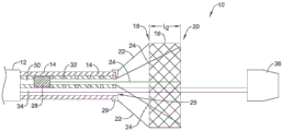
Fig. 2 shows the medical device system 10 in a partially deployed configuration. As shown in fig. 2, the outer sheath 12 of the medical device system 10 has been retracted in a proximal direction to a position proximal of the medical implant 16. In other words, the outer sheath 12 has been retracted (e.g., pulled back) in a proximal direction such that the medical device implant 16 is exposed from the compact, low-profile delivery position to the partially deployed position.
In at least some examples contemplated herein, the medical device implant 16 may be designed to self-expand once released from the outer sheath 12. However, as shown in fig. 2, the medical device system 10 may be designed such that full expansion of the implant 16 in the radial direction may be limited. For example, FIG. 2 is shown with a partially deployed position (represented by length "L1") medical device implant 16.
Fig. 2 also shows that, in some examples, the implant 16 may include one or more support members 22 coupled to the proximal end 18 of the implant 16. Also, fig. 2 shows that, in some examples, the implant 16 may include one or more translating members 24 coupled to the distal end 20 of the implant 16. Additionally, in some examples (such as shown in fig. 2), translating member 24 and support member 22 may work together to maintain the implant in a partially deployed position after the outer sheath is retracted to expose implant 16. For example, fig. 2 shows that the support members 22 may be designed such that the distal end of each support member may be joined to the proximal end of the implant 16, and the proximal end of each support member 22 may be joined to the distal end of the inner catheter 14. For example, fig. 2 shows that the proximal end of support member 22 may be attached to a restraining fitting 28, which restraining fitting 28 is rigidly secured to the distal end of inner catheter 14. It is further understood that in some instances, the support member 22 may be designed to limit proximal movement of the proximal end 18 of the implant 16 relative to the distal end of the inner catheter 14.
Additionally, the translating member 24 can be designed to translate in the distal-to-proximal direction such that translation of the translating member (e.g., via manipulation of the handle by an operator) can "pull" the distal end 20 of the implant closer to the proximal end 18 of the implant 16.
For example, fig. 3 illustrates distal-to-proximal translation of translating member 24. It should be appreciated that if the support member 22 limits proximal movement of the proximal end 18 of the implant 16 as the translation member 24 translates proximally, the implant 16 may shorten (along the longitudinal axis of the implant 16) and may also expand radially outward. The shortening and radial expansion of the implant 16 can be seen by comparing the shape and position of the implant 16 in fig. 2 with the shape and position of the implant 16 in fig. 3. The position of the implant 16 shown in fig. 3 may be described as the fully deployed position of the implant 16 (as compared to the partially deployed position of the implant 16 shown in fig. 2). Further, fig. 3 depicts the fully deployed length of implant 16 as L2From this distance L2Less than the distance L shown in fig. 21。
Additionally, it should be understood that translating members 24 may be designed to be extendable in a proximal-to-distal direction such that they are capable of elongating (e.g., lengthening) implant 16 (along its longitudinal axis). In other words, the implant 16 can be transitioned between the partially deployed position (shown in fig. 2) and the fully deployed position (shown in fig. 3) by translation (proximal or distal) of the translation member 24 along the longitudinal axis, as the support member 22 limits movement of the proximal end 18 of the implant 16.
It should be noted that the above description and illustrations regarding the arrangement, attachment features, and operation of support member 22 and translation member 24 as they engage and function relative to implant 16 are schematic. It can be appreciated that the design (e.g., arrangement, attachment features, operation, etc.) of both the support member 22 and the translation member 24 can vary as they are associated and function relative to the implant 16. For example, the translating member 24 and the support member 22 can be designed, arranged, and operated in various ways to achieve the partially and fully deployed configurations of the implant 16.
In some examples, the operator can manipulate the translating member 24 via the handle member 17. For example, the handle 17 may include an actuation member designed to control the translation of the translating member 24. Fig. 2 shows that the handle member 17 may be coupled to the translating member 24 via an actuation shaft 30 and a coupling member 28. For example, as described in more detail below, fig. 2 shows that the proximal end of translating member 24 can be coupled to the distal end of coupling member 28. Additionally, FIG. 2 also shows that the distal end of the actuation shaft 30 may be coupled to the proximal end of the coupling member 28. Further, although not shown in fig. 2, it is understood that the actuation shaft 30 may extend from the linking member 28 to the handle member 17 throughout the length of the inner shaft 14.
For purposes of discussion herein, the inner shaft 14 may also be referred to as an inner member or liner 14. The liner 14 may include many of the different features shown in the figures described herein. For example, the liner may include a lumen 25. Further, the translating member 24, the coupler 28, the actuation shaft 30, a guidewire lumen 34 (described below), and a gathering coil 32 (described below) may be disposed within the lumen 25. These are examples only. The form of the inner liner 14 may vary. For example, the inner liner 14 may include a single cavity, multiple cavities, or no cavities.
As noted above, fig. 2 and 3 show translating member 24 translating in the distal-to-proximal direction (which shortens and radially expands implant 16, as discussed above). However, fig. 3 also shows that translation of the translating member 24 in the distal-to-proximal direction is achieved by translation of the actuating shaft 30 and the linking member 28 within the lumen 25 of the inner catheter 14. For example, when the actuation shaft 30 is retracted (e.g., pulled proximally within the lumen 25 of the inner catheter 14), it retracts the coupling member 28 proximally, which in turn retracts the translating member 24 in a proximal direction.
In some instances, it may be desirable for the translating member 24 to remain in a generally linear configuration when translated within the lumen 25 of the inner catheter 14. Thus, in some examples, the medical device system 10 may include components designed to limit and/or prevent the translating members 24 from twisting relative to each other within the lumen 25 of the inner catheter 14. For example, fig. 2 and 3 show the focus coil 32 wrapped around the translating member 24 such that the focus coil holds the translating member 24 in a generally linear configuration (thereby limiting and/or preventing twisting of the translating member 24 within the inner lumen 25) as the translating member 24 translates through the inner lumen 25 of the inner catheter 14.
Fig. 2 and 3 further illustrate that the proximal end of the gathering coil 32 may be positioned adjacent the distal end of the linking member 28, and the distal end of the gathering coil 32 may be positioned adjacent the distal end of the inner catheter 14. Specifically, the distal end of the gathering coil 32 is prevented from extending distally beyond the distal end of the inner catheter 14 by the restraining fitting 29. In other words, the distal end of the gathering coil 32 may contact the suppression fitting 29.
It is further understood that the compression coil 32 may be positioned within the lumen 25 of the inner catheter 14 such that the compression coil 32 may be lengthened and shortened (e.g., the length of the compression coil may be adjusted) within the lumen 25 of the inner catheter 14. For example, as the linking member 28 translates in a proximal direction (shown in fig. 3 as compared to fig. 2), the gathering coil can elongate while continuing to gather and/or expand the translating member 24 in a generally linear configuration.
Fig. 2 and 3 further illustrate that the medical device system 10 may include a tubular guidewire member 34 extending within the lumen 25 of the inner catheter 14. The tubular guidewire member 34 can be designed to allow the guidewire to extend and translate therein. In addition, a tubular wire member 34 can extend from the handle member 17, through the lumen 25 of the inner member 14, through the implant 16, and terminate at a nose cone 36. Further, the tubular guidewire member 34 may include a lumen (not shown in fig. 2 or 3) that allows a guidewire to be advanced therein. In other words, the medical device 10 may be advanced over a guidewire extending within the lumen of the tubular guidewire member 34 to a target site within the body.
Fig. 4 shows a cross-section of a portion of the medical device system 10 described with respect to fig. 1-3. In particular, as noted above, fig. 4 shows an actuating shaft 30 coupled to coupler 28, translating member 24 coupled to coupler 28, and a gathering coil 32 (whose distal end is positioned adjacent suppression fitting 29, as discussed above) wound about translating member 24. Fig. 4 also shows that the outer surface 37 of the gathering coil 32 can contact both the inner surface 46 of the inner catheter 14 and the outer surface 44 of the wire guide member 34. Thus, it can be further appreciated that the outer diameter (and thus the inner diameter) of the gathering coil 32 can remain constant as the gathering coil elongates or shortens as the coupler 28 translates within the lumen 25 of the inner catheter 14.
Additionally, it is understood that medical device system 10 may be designed such that both the proximal and distal ends of the gathering coil 32 may not be fixedly attached to adjacent structures (e.g., may not be attached to the linking member 28 and/or restraint fitting 29). It will be appreciated that by not attaching either end of the compression coil 32 to an adjacent structure (e.g., the linking member 28 and/or the suppression fitting 29), the compression coil 32 may be allowed to freely twist while lengthening or shortening within the lumen 25. This freedom of movement allows the gathering coil 32 to maintain an inner diameter that gathers (e.g., includes) the translating members 24 closely to each other as the translating members 24 linearly translate within the lumen 25 of the inner catheter 14.
Fig. 4 also shows that the coupler 28 may be positioned within the lumen 25 of the inner catheter 14 such that a bottom surface 45 of the coupler 28 is adjacent the outer surface 44 of the guide wire member 34. In some examples, the coupler 28 may be designed such that it is not rigidly fixed to the wire member 34 and, therefore, may translate relative to the wire member 34. In other examples, the coupler 28 may be designed such that it is rigidly fixed to the wire member 34, so that translation of the coupler 28 (which may itself occur through translation of the actuation shaft 30) may also translate both the wire member 34 and the translation member 24. In other words, it can be appreciated that with the coupler 28 rigidly fixed to the wire member 34, manipulation of the actuation shaft 30 by the operator via the handle 17 can translate both the translating member 24 and the wire member 34 together such that either the translating member 24 or the wire member 34 translates distally or proximally will translate both the translating member 24 or the wire member 34 by a corresponding equal amount. Further, it is understood that the same effect can be achieved by joining the wire member 34 and the actuation shaft 30 anywhere along the medical device system 10, including joining the wire member 34 and the actuation shaft 30 to one another in the handle member 17. It is understood that the guidewire member 34 and the actuation shaft 30 can be joined together at more than one location along the medical device system 10.
In some cases, it may be desirable for nose cone 36 to translate in a proximal direction as implantable medical device 16 transitions from the collapsed configuration to the fully deployed configuration (as shown in fig. 1-3). As can be appreciated from the above discussion, because the nose cone 36 is connected to the distal end of the wire member 34, as the wire member 34 translates with the translating member 24 (via the coupler 28 and the actuation shaft 30), the nose cone 36 correspondingly translates in a proximal direction as the translating member acts to transition the implantable medical device 16 from the collapsed configuration to the fully deployed configuration.
Fig. 4 further illustrates that, in some cases, the actuation shaft 30 may include an actuation rod 40 positioned within the lumen of the coil member 38. Similar to that described above with respect to the gathering coil 32, the outer surface of the coil member 38 may contact both the inner surface 46 of the inner catheter 14 and the outer surface 44 of the guide wire member 34. It can be appreciated that the outer surface of the coil member 38 can reduce the frictional force of the actuation shaft 30 along the inner surface 46 of the inner catheter 14 as compared to the frictional force that would exist if the actuation shaft 30 did not include a coil member. For example, in addition to increasing the ease with which the actuation shaft can flex/bend within the lumen 25 of the inner catheter 14, the coil member 38 also provides "point-to-point" contact along the inner surface 46 of the inner member 14. These properties reduce the overall surface friction between the outer surface of the actuation shaft 30 and the inner surface 46 of the inner conduit 14 (as compared to a similarly sized solid rod). The reduction in friction may further reduce the likelihood that the actuation shaft 30 will store and release energy in the form of a "kickback" effect. It is contemplated that coil member 38 may extend along a portion or the entire length of actuator rod 40. Also, actuating rod 40 may extend from the proximal end of coupler 28 to handle member 17. Furthermore, the above-described functional characteristics of the coil member 38 are not intended to be limiting. For example, it is contemplated that the coil member 38 may be used to conduct electricity along a portion thereof (e.g., along a surface or other portion of the coil member 38).
Fig. 4 also shows that, in some examples, the guidewire member 34 may include a reinforcing coil embedded in the tubular wall thereof. For example, fig. 4 shows the coil 48 positioned within the wall of the guide wire member 34. The coil 48 may provide additional strength and flexibility to the wire member 34. Further, fig. 4 shows the lumen 42 of the guide wire member 34. It is understood that a guidewire (not shown) may extend within the lumen 42 of the guidewire member 34.
Fig. 5 shows a cross-sectional view along line 5-5 of fig. 4. As mentioned above, the inner conduit 14 may include a number of features. For example, inner conduit 14 may include one or more tensile members 50a/50 b. Tensile members 50a/50b may take the form of wires (e.g., metal wires), braids, cables, stranded cables, composite structures, and the like. In one example, tensile members 50a/50b are both metal wires. In another case, tensile members 50a/50b are both metal braids. The braid may also include axial strands made of a suitable polymer or metal (e.g., aramid). Tensile members 50a/50b may be made of the same material and/or have the same configuration. Alternatively, tensile members 50a/50b may differ from one another. Further, although FIG. 2 illustrates inner conduit 14 as including two tensile members 50a/50b, this is not intended to be limiting. Other numbers of tensile members 50a/50b are contemplated, such as one, three, four, five, six, seven, or more.
Fig. 5 also illustrates that the lumen 25 of the inner catheter 14 can be shaped to limit twisting of the actuation shaft 30 and the wire guide member 34. For example, fig. 5 illustrates that the lumen 25 may be non-circular. For example, the shape of the lumen 25 may be oval, square, rectangular, etc. It can be appreciated that as the inner catheter 14 is rotated within the inner lumen of the outer member 12, the shape of the inner lumen 25 can force both the actuation shaft 30 and the guide wire member 34 to maintain their respective spatial relationships, as shown in fig. 5. In other words, the shape of the lumen 25 forces the actuation shaft 30 and the guide wire member 34 to maintain their positions relative to each other regardless of the effects of bending, rotation, flexing, etc. of the inner catheter 14.
In addition, fig. 5 also shows that the actuation shaft 30 and the guide wire member are positioned adjacent to each other within the lumen 25. As described above, the actuation shaft 30 may include an actuation rod 40 positioned within the lumen of the coil member 38. Further, fig. 5 shows a guide wire member 34. The guidewire member 34 may include a reinforcement coil 48 embedded in the tubular wall thereof. For example, fig. 5 shows the coil 48 embedded in the wall of the guide wire member 34 for positioning. The coil 48 may provide additional strength and flexibility to the wire member 34. Further, fig. 5 shows the lumen 42 of the guide wire member 34.
Fig. 6 shows a cross-sectional view along line 6-6 of fig. 4. Fig. 4 shows the gathering coil 32, coupler 28 and guide wire member 34 positioned within the lumen 25. In addition, fig. 6 shows that a gathering coil 32 may be wrapped around three translating members 24 positioned therein. The translating members 24 may be equally spaced from each other. For example, the translating members 24 may be spaced at an angle of approximately 120 degrees relative to each other. Further, while fig. 6 illustrates three translating members 24, it is contemplated that more or less than three translating members 24 may be used within the medical device system 10. For example, the medical device system 10 can include 1, 2, 3, 4, 5, 6, 7, 8, 9, 10, or more translating members 24.
In addition, FIG. 6 shows that inner conduit 14 may include one or more tensile members 50a/50 b. Tensile members 50a/50b may take the form of wires (e.g., metal wires), braids, cables, stranded cables, composite structures, and the like. Also, figure 6 illustrates that tensile members 50a/50b may be positioned opposite each other on either side of cavity 25.
In addition, fig. 5 shows a guide wire member 34. The guidewire member 34 may include a reinforcement coil 48 embedded in the tubular wall thereof. For example, fig. 5 shows the coil 48 embedded in the wall of the guide wire member 34 for positioning. The coil 48 may provide additional strength and flexibility to the wire member 34. Further, fig. 5 shows the lumen 42 of the guide wire member 34.
Fig. 6 also shows a coupler 28 that includes a bottom surface 45 (as described above). As shown, the bottom surface 45 is shaped to mate with the outer surface of the guide wire member 34. For example, in some examples, the bottom surface 45 may include a curved portion that mates with a radius defined by the outer surface 44 of the guide wire member 34. As described above, the bottom surface 45 of the coupler 28 may or may not be rigidly fixed to the wire member 34.
Fig. 7 illustrates a detailed view of a portion of the medical device system 10 shown in fig. 6. Fig. 7 shows a cross-sectional view of the coupler 28. The coupler 28 may include a base member 65, a first cover 67, and a second cover 69. The first cover 67 and the second cover 69 may be separate components from the base member 65. Also, the first and second covers 67, 69 may be attached to the base member 65 by welding or any other suitable process.
As shown, a portion of actuating lever 40 may extend into a portion of coupler 28, contacting both base member 65 and first cover 67. Similarly, portions of translating member 24 may extend into a portion of coupler 28, contacting both base member 65 and first cover 69. As can be seen in fig. 7, base member 65 may include one or more protrusions 60 that mate with one or more recesses 61 in actuating lever 40. Similarly, as can be seen in fig. 7, the base member 65 may include one or more protrusions 62 that mate with one or more recesses 63 in the translating member 24. It will also be appreciated that engaging the corresponding protrusion with the recess (in both actuating lever 40 and translating member 24) may limit translational movement of both actuating lever 40 and translating member 24 relative to the coupling. In other words, engagement of the respective protrusions with the recesses (in both actuation lever 40 and translating member 24) may prevent actuation lever 40 and translating member 24 from translating independently of coupler 28 (and relative to each other). However, it will be further appreciated that engagement of the respective protrusions with the recesses (in both actuation lever 40 and translating member 24) may allow actuation lever 40 to spin/rotate on its own longitudinal axis. Additionally, it is appreciated that the coupling 28 (including the base member 65, the first cover 67, and the second cover 69) may allow for different materials to be joined as they are mechanically "captured" and preferentially oriented within the coupling 28. In some cases, the coupling 28 may be defined as a "rotator".
Materials that may be used for the various components of the medical devices and/or systems 10 disclosed herein may include those typically associated with medical devices. However, this is not intended to limit the devices and methods described herein, as the discussion is applicable to the medical devices and/or other components of the system 10 disclosed herein, including the various shafts, liners, components, etc., described with respect thereto.
The
medical device 10 may be made of a metal, metal alloy, polymer (some examples of which are disclosed below), metal-polymer composite, ceramic, combinations thereof, or the like, or other suitable materials. Some examples of suitable polymers may include polytetrafluoroethylene (PTFE: (R) (R))PTFE), Ethylene Tetrafluoroethylene (ETFE), Fluorinated Ethylene Propylene (FEP), polyoxymethylene (POM, e.g., available from DuPont
) Polyether block esters, polyurethanes (e.g., Polyurethane 85A), polypropylene (PP), polyvinyl chloride (PVC), polyether esters (e.g., available from DSM Engineering Plastics)
) Ether-or ester-based copolymers (e.g., butylene/poly (alkylene ether) phthalate) and/or other polyester elastomers such as those available from DuPont
) Polyamides (e.g. available from Bayer)
Or available from Elf Atochem
) Elastomeric polyamides, polyamide/ether blocks, polyether block amides (PEBA, for example, available under the trade name PEBA)
Obtained), ethylene vinyl acetate copolymer (EVA), silicone, Polyethylene (PE), High Density Polyethylene (HDPE), polyester, Marlex high density polyethylene, Marlex low density polyethylene, linear low density polyethylene (e.g.,
) Ultra High Molecular Weight (UHMW) polyethylene, polypropylene, polybutylene terephthalate (PBT), polyethylene terephthalate (PET), polybutylene terephthalate, polyethylene naphthalate (PEN), Polyetheretherketone (PEEK), Polyimide (PI), Polyetherimide (PEI), polyphenylene sulfide (PPS), polyphenylene oxide (PPO), poly (paraphenylene terephthalamide) (e.g.,
) Polysulfone, nylon-12 (such as available from EMS American Grilon)
) Perfluoro (propyl vinyl ether) (PFA), ethylene vinyl alcohol, polyolefins, polystyrene, epoxy resins, polyvinylidene chloride (PVdC), poly (styrene-b-isobutylene-b-styrene) (e.g., SIBS and/or SIBS 50A), polycarbonate, ionomers, biocompatible polymers, other suitable materials, or mixtures, combinations, copolymers, polymer/metal composites thereof, and the like. In some embodiments, the jacket may be blended with a Liquid Crystal Polymer (LCP).
Some examples of suitable metals and metal alloys include stainless steels, such as 304V, 304L, and 316LV stainless steels; mild steel; nickel titanium alloys, such as linear elastic and/or superelastic nitinol; other nickel alloys, such as nickel-chromium-molybdenum alloys (e.g., UNS: N06625, such as
625, a first step of; UNS: N06022, such as
UNS N10276, such as
Others
Alloys, etc.), nickel-copper alloys (e.g., UNS: N04400, such as
400、
400、
400, etc.), nickel cobalt chromium molybdenumGold (e.g., UNS: R30035, such as
Etc.), nickel-molybdenum alloys (e.g., UNS: N10665, such as
ALLOY
) Other nickel-chromium alloys, other nickel-molybdenum alloys, other nickel-cobalt alloys, other nickel-iron alloys, other nickel-copper alloys, other nickel-tungsten alloys or tungsten alloys, and the like, cobalt-chromium alloys, cobalt-chromium-molybdenum alloys (e.g., UNS: R30003, such as
Etc.), platinum-rich stainless steel, titanium, combinations thereof, etc., or any other suitable material.
In at least some embodiments, some or all of the medical device 10 can also be doped with, made of, or otherwise include a radiopaque material. Radiopaque materials are understood to be materials that are capable of producing a relatively bright image on a fluoroscopic screen or another imaging technique during a medical procedure. The relatively bright image assists the user of the medical device 10 in determining his or her position. Some examples of radiopaque materials may include, but are not limited to, gold, platinum, palladium, tantalum, tungsten alloys, polymeric materials loaded with radiopaque fillers (e.g., barium sulfate, bismuth subcarbonate, etc.), and the like. Additionally, other radiopaque marker bands and/or coils may also be incorporated into the design of the medical device 10 to achieve the same result.
In some embodiments, the
medical device 10 is given a degree of Magnetic Resonance Imaging (MRI) compatibility. For example, the
medical device 10 may be made of a material that does not substantially distort the image and generates a large number of artifacts (e.g., gaps in the image). For example, certain ferromagnetic materials may be unsuitable because they may generate artifacts in MRI images. The
medical device 10 may also be made of a material that the MRI machine is capable of imaging. Some materials that exhibit these properties include, for example,tungsten, cobalt-chromium-molybdenum alloys (e.g., UNS: R44003, such as
Etc.), nickel-cobalt-chromium-molybdenum alloys (e.g., UNS: r44035, such as MP35-
Etc.), nitinol, etc., and others.
It should be understood that this disclosure is, in many respects, only illustrative. Changes may be made in details, particularly in matters of shape, size, and arrangement of steps without exceeding the scope of the disclosure. To the extent appropriate, this may include using any of the features of one example embodiment in other embodiments. The scope of the invention is, of course, defined in the language in which the appended claims are expressed.