CN110618434B - Tunnel positioning system based on laser radar and positioning method thereof - Google Patents
Tunnel positioning system based on laser radar and positioning method thereof Download PDFInfo
- Publication number
- CN110618434B CN110618434B CN201911046049.XA CN201911046049A CN110618434B CN 110618434 B CN110618434 B CN 110618434B CN 201911046049 A CN201911046049 A CN 201911046049A CN 110618434 B CN110618434 B CN 110618434B
- Authority
- CN
- China
- Prior art keywords
- road signs
- tunnel
- vehicle
- point cloud
- road
- Prior art date
- Legal status (The legal status is an assumption and is not a legal conclusion. Google has not performed a legal analysis and makes no representation as to the accuracy of the status listed.)
- Active
Links
Images


Landscapes
- Traffic Control Systems (AREA)
- Optical Radar Systems And Details Thereof (AREA)
- Navigation (AREA)
Abstract
本发明提供一种基于激光雷达的隧道内定位系统及其定位方法,属于汽车自动驾驶领域。系统包括:布设于隧道两侧的路标、安装于车顶的激光雷达和安装于车辆后备箱中的图形处理器GPU计算平台;方法包括:步骤1,在隧道两侧布设路标,利用安装了激光雷达的车辆通过隧道,采集点云数据,结合隧道内的里程信息生成点云概率地图;步骤2,当车辆驶入隧道入口后,判断车辆本地是否存在所驶入隧道的点云概率地图,如果存在,配准本地存储的点云概率地图,否则根据路标数据库来对车辆进行定位。本发明通过在隧道两侧巧妙的布设路标,实现路标的差异化;采用不同的定位算法,实现在明暗对比较大的隧道中准确进行车辆定位,具有抗环境干扰能力强的优点。

The invention provides an in-tunnel positioning system based on laser radar and a positioning method thereof, belonging to the field of automobile automatic driving. The system includes: road signs arranged on both sides of the tunnel, a lidar installed on the roof, and a graphics processor GPU computing platform installed in the trunk of the vehicle; the method includes: step 1, road signs are arranged on both sides of the tunnel, and the installed laser The radar vehicle passes through the tunnel, collects point cloud data, and combines the mileage information in the tunnel to generate a point cloud probability map; Step 2, when the vehicle enters the tunnel entrance, determine whether the vehicle has a point cloud probability map of the tunnel it entered. If there is, register the locally stored point cloud probability map, otherwise locate the vehicle according to the road sign database. The invention realizes the differentiation of road signs by cleverly laying road signs on both sides of the tunnel; adopts different positioning algorithms to realize accurate vehicle positioning in tunnels with large contrast between light and dark, and has the advantages of strong anti-environmental interference capability.
Description
技术领域technical field
本发明属于汽车自动驾驶领域,具体涉及一种基于车载激光雷达的隧道定位系统及方法。The invention belongs to the field of automobile automatic driving, and in particular relates to a tunnel positioning system and method based on a vehicle-mounted laser radar.
背景技术Background technique
对于自动驾驶车辆,车辆自身的位置是整个自动驾驶系统的基础信息之一,其精确到厘米级的输入是路径规划等功能实现的保障。For autonomous vehicles, the position of the vehicle itself is one of the basic information of the entire autonomous driving system, and its input accurate to the centimeter level is the guarantee for the realization of functions such as path planning.
目前在开阔地域,绝大多数自动驾驶车辆依靠全球导航卫星系统(GlobalNavigation Satellite System,GNSS)来获取当前位置信息,依赖载波相位差分(Real-time kinematic,RTK)技术将GNSS系统的精确度提高至厘米级;在高大建筑或林荫道等卫星信号被遮挡的情况下,自动驾驶车辆大多采用激光雷达采集环境特征信息,利用特征匹配先验地图获得自身在地图中的位置。At present, in open areas, most autonomous vehicles rely on the Global Navigation Satellite System (GNSS) to obtain the current position information, and rely on the carrier phase difference (Real-time kinematic, RTK) technology to improve the accuracy of the GNSS system to Centimeter-level; when satellite signals such as tall buildings or boulevards are blocked, most autonomous vehicles use lidar to collect environmental feature information, and use the feature to match the prior map to obtain its own position on the map.
当前已有多种定位技术应用在隧道场景中,如采用双目相机识别路沿荧光反射以及标识牌等,其运用SLAM(Simultaneous Localization And Mapping,同步定位与地图构建)技术进行定位,但在暗光等光照条件差的环境中无法达到期望水平;另有采用摄像头与毫米波雷达识别隧道内特征与先验地图比对进行定位,这种方法在特征较少的平直隧道中不适用;除此以外,有使用光照传感器和气压计感知路灯之间的明暗变化等进行里程计算从而实现定位,但这种方法不能实现在无灯隧道中的定位。At present, a variety of positioning technologies have been applied in tunnel scenes, such as the use of binocular cameras to identify roadside fluorescent reflections and signs, etc., which use SLAM (Simultaneous Localization And Mapping) technology for positioning, but in the dark In the environment with poor lighting conditions such as light, the expected level cannot be achieved; in addition, cameras and millimeter-wave radar are used to identify the features in the tunnel and compare with the prior map for localization. This method is not suitable for straight tunnels with few features; In addition, there are lighting sensors and barometers used to sense the light and dark changes between street lights to perform mileage calculation to achieve positioning, but this method cannot achieve positioning in a tunnel without lights.
普通激光雷达的点云配准定位算法依赖特征点和特征面,而大多数结构化隧道的墙壁平直相似,无法为雷达提供足够的几何特征信息用于匹配位置。也有在隧道壁上安装反光板为激光雷达提供定位基准的做法,这种方法通过判断反光板相对于雷达的位移获得车辆的位移信息,将位移累计为里程计,但其未能做到在定位丢失后快速准确的重新定位。The point cloud registration and localization algorithm of ordinary lidar relies on feature points and feature surfaces, and the walls of most structured tunnels are flat and similar, which cannot provide enough geometric feature information for radar to match the position. There is also the practice of installing a reflector on the tunnel wall to provide a positioning reference for the lidar. This method obtains the displacement information of the vehicle by judging the displacement of the reflector relative to the radar, and accumulates the displacement as an odometer, but it fails to achieve positioning. Fast and accurate relocation after loss.
例如:公开号为CN108254776A的中国专利申请在2018年7月6日公开的基于路沿荧光反射和双目相机的隧道定位系统及方法,该系统及方法使用摄像头识别隧道内路沿和标牌等设施,将其作为路标运用VSLAM(利用视觉系统实现自主定位与地图创建)技术进行定位,该方法对光线要求极高,不适合明暗对比大的隧道等场景。公开号为CN109031304A的中国专利申请在2018年12月18日公开的基于视觉和毫米波雷达地图特征的隧道内车辆定位方法,该方法使用毫米波雷达识别特征与先验特征地图比对,辅助IMU与视觉进行定位。毫米波雷达不能识别隧道顶部的特征,而水平方向的特征过于稀疏,其定位效果的鲁棒性较差。For example: Chinese patent application with publication number CN108254776A disclosed on July 6, 2018 a tunnel positioning system and method based on roadside fluorescence reflection and binocular cameras, the system and method use cameras to identify facilities such as roadsides and signs in the tunnel , use it as a road sign and use VSLAM (the use of vision system to achieve autonomous positioning and map creation) technology for positioning, this method has extremely high requirements on light and is not suitable for scenes such as tunnels with large contrast between light and dark. The Chinese patent application with publication number CN109031304A disclosed on December 18, 2018 a method for locating vehicles in tunnels based on visual and millimeter-wave radar map features. The method uses millimeter-wave radar identification features to compare with prior feature maps to assist IMU Orientation with vision. Millimeter-wave radar cannot identify the features at the top of the tunnel, and the features in the horizontal direction are too sparse, and the robustness of the localization effect is poor.
因此,当前缺乏一种高精度、重定位性好的适应隧道环境的定位方法。Therefore, there is currently a lack of a localization method with high accuracy and good relocation performance that adapts to the tunnel environment.
发明内容SUMMARY OF THE INVENTION
本发明针对目前在隧道环境下车辆定位精度不高、重定位性不好的问题,提供了一种基于激光雷达的隧道内定位系统及其定位方法。Aiming at the problems of low vehicle positioning accuracy and poor relocation performance in the current tunnel environment, the present invention provides an in-tunnel positioning system and a positioning method based on laser radar.
本发明的基于激光雷达的隧道定位系统,包括:布设于隧道两侧的路标、安装于车顶的激光雷达和安装于车辆后备箱中的GPU(图形处理器)计算平台。其中,路标具有两个相同的路标反射面,用于两个相对行驶方向的车辆都能检测到反射面。路标在隧道入口处开始布设,隧道入口处的左右第一个路标对称布设,之后路标以不同间距进行布设,以使得两侧的路标错开布设。对称布设的左右路标表示同一里程位置,通过记录左右两侧相邻路标间的距离,获得隧道内的路标的里程位置。激光雷达的作用是传感器,采用多线激光雷达,并安装于车顶支架上,由于要采集路标的点云信息,需保证足够的安装高度来探测到路标。激光雷达发射的激光被路标反射面反射,激光雷达捕捉到点云数据并发送给车辆本地的GPU计算平台。车辆本地的GPU计算平台用于处理激光雷达接收的点云数据,对车辆进行隧道内的定位。在车辆的GPU计算平台内存储有路标数据库以及生成的隧道点云概率地图;当接收到激光雷达的点云数据后,若存储有车辆所驶入的隧道的点云概率地图,则通过点云配准进行车辆定位,否则利用路标数据库进行路标基点算法对车辆定位。所述的隧道的点云概率地图是预先利用安装了激光雷达的车辆通过隧道,采集点云数据,结合隧道内的里程信息生成的。所述的路标数据库中存储路标设置的位置、设置的路标间距、左右相邻路标的标准差值以及路标所属的里程段,同一个里程段内的路标间距是一样的。所述的路标基点算法集成在GPU计算平台上,包括:根据车辆采集的点云数据,识别隧道内左右两侧的路标,然后根据识别出的路标的间距确定车辆所处的里程段,计算左右相邻两个路标之间的纵向距离差值ΔD,遍历所处里程段中左右相邻路标的标准差值,找到与ΔD最相近的一组路标,根据所找到的路标来定位车辆的当前位置。相应地,本发明提供了一种基于激光雷达的隧道定位方法,包括:The tunnel positioning system based on lidar of the present invention includes road signs arranged on both sides of the tunnel, lidar mounted on the roof of the vehicle, and a GPU (graphics processing unit) computing platform mounted in the trunk of the vehicle. Among them, the road sign has two identical road sign reflection surfaces, which can be detected by vehicles in two opposite driving directions. The road signs are laid out at the entrance of the tunnel. The first road signs on the left and right at the entrance of the tunnel are arranged symmetrically, and then the road signs are arranged at different intervals, so that the road signs on both sides are staggered. The left and right road signs arranged symmetrically represent the same mileage position. By recording the distance between the adjacent road signs on the left and right sides, the mileage position of the road signs in the tunnel is obtained. The function of the lidar is a sensor. It adopts a multi-line lidar and is installed on the roof bracket. Since the point cloud information of the road sign needs to be collected, it is necessary to ensure a sufficient installation height to detect the road sign. The laser light emitted by the lidar is reflected by the reflective surface of the road sign, and the lidar captures the point cloud data and sends it to the local GPU computing platform of the vehicle. The GPU computing platform local to the vehicle is used to process the point cloud data received by the lidar, and to locate the vehicle in the tunnel. The road sign database and the generated tunnel point cloud probability map are stored in the GPU computing platform of the vehicle; after receiving the point cloud data of the lidar, if the point cloud probability map of the tunnel into which the vehicle entered is stored, the point cloud The registration is used to locate the vehicle, otherwise the road sign database is used to locate the vehicle with the road sign base point algorithm. The point cloud probability map of the tunnel is generated by using vehicles equipped with lidar to pass through the tunnel in advance, collecting point cloud data, and combining the mileage information in the tunnel. The road sign database stores the set position of road signs, the set road sign spacing, the standard deviation value of the left and right adjacent road signs, and the mileage section to which the road signs belong, and the road sign spacing in the same mileage section is the same. The road sign base point algorithm is integrated on the GPU computing platform, including: identifying the road signs on the left and right sides of the tunnel according to the point cloud data collected by the vehicle, and then determining the mileage segment where the vehicle is located according to the distance between the identified road signs, and calculating the left and right sides. The longitudinal distance difference ΔD between two adjacent road signs, traverse the standard deviation value of the left and right adjacent road signs in the mileage, find a group of road signs closest to ΔD, and locate the current position of the vehicle according to the found road signs . Correspondingly, the present invention provides a laser radar-based tunnel positioning method, comprising:
步骤1,在隧道两侧布设路标,利用安装了激光雷达的车辆通过隧道,采集点云数据,结合隧道内的里程信息生成点云概率地图;Step 1, lay road signs on both sides of the tunnel, use vehicles equipped with lidar to pass through the tunnel, collect point cloud data, and generate a point cloud probability map based on the mileage information in the tunnel;
所述的路标具有两个相同的路标反射面,以使得两个相对行驶方向的车辆都能检测到反射面;路标在隧道入口处开始布设,在隧道入口处的左右第一个路标对称布设,表示同一里程位置,之后左右两侧的路标以不同间距进行布设;通过记录左右两侧相邻路标间的距离,获得隧道内的路标的里程位置;The road sign has two identical road sign reflecting surfaces, so that vehicles in two opposite driving directions can detect the reflecting surfaces; Indicates the same mileage position, and then the road signs on the left and right sides are arranged at different intervals; by recording the distance between the adjacent road signs on the left and right sides, the mileage position of the road signs in the tunnel is obtained;
步骤2,当车辆驶入隧道入口后,判断车辆本地是否存在所驶入隧道的点云概率地图,如果存在,则执行步骤3,否则执行步骤4;Step 2, when the vehicle enters the tunnel entrance, determine whether there is a point cloud probability map of the tunnel entered by the vehicle locally, if so, execute step 3, otherwise, execute step 4;
步骤3,根据车辆采集的当前时刻的激光雷达点云数据,配准本地存储的点云概率地图,对车辆进行定位;Step 3, according to the LiDAR point cloud data collected by the vehicle at the current moment, register the locally stored point cloud probability map, and locate the vehicle;
步骤4,根据车辆采集的点云数据,识别隧道内左右两侧的路标,然后根据路标数据库来对车辆进行定位。所述的路标数据库中存储路标设置的位置、设置的路标间距、相邻路标的标准差值以及路标所属的里程段;同一个里程段内的路标间距是一样的。在识别出路标后,首先根据路标间距确定车辆所处的里程段,然后计算左右相邻两个路标之间的纵向距离差值ΔD,遍历所处里程段中左右相邻路标的标准差值,找到与ΔD最相近的一组路标,根据所找到的路标来定位车辆的当前位置。Step 4: Identify the road signs on the left and right sides of the tunnel according to the point cloud data collected by the vehicle, and then locate the vehicle according to the road sign database. The road sign database stores the set position of road signs, the set road sign spacing, the standard deviation value of adjacent road signs and the mileage section to which the road signs belong; the road sign spacing in the same mileage section is the same. After identifying the road signs, first determine the mileage segment where the vehicle is located according to the distance between the road signs, then calculate the longitudinal distance difference ΔD between the left and right adjacent road signs, and traverse the standard deviation value of the left and right adjacent road signs in the mileage segment, Find a set of road signs closest to ΔD, and locate the current position of the vehicle according to the found road signs.
本发明提供了一种新的路标布设方案,所述路标布设于隧道两侧的墙壁上,两侧的路标布设间距不相同。在隧道入口处两侧进行路标对称布设,表示同一里程位置,此后左右两侧分别以不同间距进行布设,经过若干里程后两侧路标可再次实现对齐,在这一段隧道中,通过记录左右两侧相邻路标间的距离,实现对隧道位置的标定。在接下来的一段隧道中,改变两侧路标的布设间距后重复上述布设。在以后的隧道中以此类推,直到隧道结束。The present invention provides a new road sign layout scheme, the road signs are arranged on the walls on both sides of the tunnel, and the road signs on the two sides are arranged at different intervals. The road signs are arranged symmetrically on both sides of the tunnel entrance, indicating the same mileage position. After that, the left and right sides are arranged at different intervals. After several mileages, the road signs on both sides can be aligned again. In this section of the tunnel, by recording the left and right sides The distance between adjacent road signs to realize the calibration of the tunnel position. In the next section of the tunnel, repeat the above layout after changing the layout spacing of the road signs on both sides. And so on in subsequent tunnels until the end of the tunnel.
本发明的定位系统及定位方法与现有技术相比,具有以下优势和积极效果:Compared with the prior art, the positioning system and positioning method of the present invention have the following advantages and positive effects:
(1)本发明只使用了激光雷达一种传感器,实现了精度高、重定位性好的隧道内定位,定位系统的复杂性较低,定位的鲁棒性和稳定性较强;(1) The present invention uses only one type of sensor, laser radar, and realizes the positioning in the tunnel with high precision and good relocation, the complexity of the positioning system is low, and the robustness and stability of the positioning are strong;
(2)本发明的定位效果不受恶劣天气和环境影响,例如在明暗对比较大的隧道中,依然能稳定的实现定位,抗环境干扰能力极为优秀;(2) The positioning effect of the present invention is not affected by bad weather and environment, for example, in a tunnel with a large contrast between light and dark, the positioning can still be stably achieved, and the anti-environmental interference ability is extremely excellent;
(3)本发明通过巧妙地安排路标的布设位置实现了路标的差异化,降低了工程的复杂性,同时降低了生产成本;(3) The present invention realizes the differentiation of the road signs by skillfully arranging the layout positions of the road signs, reduces the complexity of the project, and reduces the production cost at the same time;
(4)本发明可以自动识别先验地图是否存在,并智能选择不同的定位算法,对不存在先验点云地图时,采用新的路标基点算法进行定位,因此在不同情况下,使用本发明方法均能在较短的处理时间内输出高频率的精准车辆位置,满足一般自动驾驶车辆对定位周期的最低需求。(4) The present invention can automatically identify whether a priori map exists, and intelligently select different positioning algorithms. When there is no priori point cloud map, a new landmark base point algorithm is used for positioning. Therefore, the present invention is used in different situations. All methods can output high-frequency precise vehicle positions in a short processing time, which can meet the minimum requirements of general autonomous vehicles for positioning cycles.
附图说明Description of drawings
图1是本发明定位系统中激光雷达及GPU计算平台的安装位置示意图;Fig. 1 is the installation position schematic diagram of laser radar and GPU computing platform in the positioning system of the present invention;
图2是本发明具体实施例中设计的在隧道两侧墙壁上布设的路标示意图;2 is a schematic diagram of road signs arranged on the walls on both sides of the tunnel designed in a specific embodiment of the present invention;
图3是在隧道两侧墙壁上布设路标的位置俯视示意图;Fig. 3 is the top view schematic diagram of the position of laying road signs on the walls on both sides of the tunnel;
图4是定位系统根据有无先验地图,自动选择不同算法的流程框图;Figure 4 is a flow chart of the positioning system automatically selecting different algorithms according to the presence or absence of a priori map;
图5在本发明方法中使用点云配准定位算法进行车辆定位的流程框图;5 is a flow chart of vehicle positioning using a point cloud registration and positioning algorithm in the method of the present invention;
图6在本发明方法中使用的路标基点定位算法的流程框图;Fig. 6 is the flow chart of the landmark base point location algorithm used in the method of the present invention;
图7在本发明方法中使用的路标基点定位算法中识别路标的流程框图;Fig. 7 is a flow chart of identifying road signs in the road sign base point positioning algorithm used in the method of the present invention;
图8在本发明方法中使用的路标基点定位算法中拟合地平面的流程框图。FIG. 8 is a flow chart of fitting the ground plane in the landmark base point location algorithm used in the method of the present invention.
图中:In the picture:
101-激光雷达;102-GPU计算平台;200-路标;201-路标上半部分的反射面;202-路标下半部分的反射面;301-隧道内道路的边沿;302-隧道两侧的墙壁;303-布设路标的位置;304-隧道的入口。101-Lidar; 102-GPU computing platform; 200-Road sign; 201-The reflective surface of the upper half of the road sign; 202-The reflective surface of the lower half of the road sign; 301-The edge of the road in the tunnel; 302-The walls on both sides of the tunnel ; 303 - the location of the road sign; 304 - the entrance of the tunnel.
具体实施方式Detailed ways
为了便于本领域普通技术人员理解和实施本发明,下面结合附图对本发明作进一步的详细和深入描述。In order to facilitate the understanding and implementation of the present invention by those of ordinary skill in the art, the present invention will be further described in detail and in-depth below with reference to the accompanying drawings.
本发明提供了一种基于激光雷达的隧道内定位系统及其定位方法,通过在隧道两侧巧妙的布设路标,实现路标的差异化,降低工程复杂性;采用本发明可以自动识别先验地图是否存在,并智能地选择不同的定位算法,实现在明暗对比较大的隧道中准确进行车辆定位,该定位系统具有抗环境干扰能力极强的优点。The invention provides an in-tunnel positioning system and a positioning method based on laser radar. By ingeniously laying road signs on both sides of the tunnel, the differentiation of road signs is realized and engineering complexity is reduced; using the invention can automatically identify whether the prior map is It exists and intelligently selects different positioning algorithms to achieve accurate vehicle positioning in tunnels with large contrast between light and dark. The positioning system has the advantage of strong anti-interference ability.
本发明提供的一种基于激光雷达的隧道内定位系统,如图1和图2所示,包括:激光雷达101、GPU计算平台102和布设于隧道两侧的路标200;激光雷达101安装于车顶,GPU计算平台102安装于车辆后备箱中;路标200包括:路标上半部分的反射面201和路标下半部分的反射面202。GPU计算平台102,主要包括:GPU计算芯片、显示屏、键盘和鼠标。A laser radar-based in-tunnel positioning system provided by the present invention, as shown in FIG. 1 and FIG. 2 , includes: a
如图1所示,为激光雷达101及GPU计算机平台102的安装位置示意图。激光雷达101安装于车顶支架上,由于要采集路标的点云信息,需保证激光雷达101足够的安装高度来探测到路标200。激光雷达101为多线激光雷达。GPU计算平台102安装在车辆后备箱内,用于处理激光雷达接收的数据、并进行计算和定位车辆。GPU计算芯片内嵌入点云配准算法和路标基点算法,进行车辆定位。显示屏主要用于显示点云地图和车辆位置以及用于调试。键盘和鼠标用于输入信息,启动和调试本系统。As shown in FIG. 1 , it is a schematic diagram of the installation positions of the
本实施例中采用32线激光雷达,用于采集隧道两侧的点云信息;车辆上还搭载12V稳定供电且功率不小于200W的供电电源,为GPU计算平台以及激光雷达供电。作为传感器,该多线激光雷达传感器具有精度高、重定位性好等优点。In this embodiment, a 32-line lidar is used to collect point cloud information on both sides of the tunnel; the vehicle is also equipped with a 12V stable power supply with a power of not less than 200W to supply power for the GPU computing platform and lidar. As a sensor, the multi-line lidar sensor has the advantages of high precision and good relocation.
本发明系统中的GPU计算芯片内集成了两种定位算法:点云配准定位算法以及路标基点定位算法。当在车辆定位前已经获得隧道内的点云概率地图并存储在本地时,对接收到的激光雷达的点云数据,使用点云配准定位算法来进行车辆定位。隧道的点云概率地图是预先利用安装了激光雷达的车辆通过隧道,采集点云数据,结合隧道内的里程信息生成的。当车辆并没有存储隧道内的先验获得的点云概率地图时,使用路标基点定位算法,利用路标数据库进行车辆定位。具体定位算法在下面对应的方法中的步骤3和4中说明。The GPU computing chip in the system of the present invention integrates two positioning algorithms: a point cloud registration positioning algorithm and a road sign base point positioning algorithm. When the point cloud probability map in the tunnel has been obtained and stored locally before the vehicle positioning, the point cloud registration and positioning algorithm is used for the vehicle positioning for the point cloud data received from the lidar. The point cloud probability map of the tunnel is generated by using vehicles equipped with lidar to pass through the tunnel in advance, collecting point cloud data, and combining the mileage information in the tunnel. When the vehicle does not store the a priori obtained point cloud probability map in the tunnel, the road sign base point location algorithm is used, and the road sign database is used to locate the vehicle. The specific positioning algorithm is described in steps 3 and 4 in the corresponding method below.
如图2所示,在本发明实施例中布设于隧道两侧墙壁上的路标200包括:路标上半部分的反射面201和路标下半部分的反射面202两部分,两部分是一体结构,但两者形状并不完全相同。路标200近似为一个三棱柱的形状,上下两个底面为等腰三角形或等边三角形,如果是等腰三角形,则腰长于底边,上下两个底面的两个等腰边和三棱柱的两个棱长围成的四边形是路标反射面,路标反射面分为上下两半部分。路标上半部分的反射面201包括四个区域,中间两个区域为两个四边形凸起;中间两区域突起高度不同、颜色不同。路标下半部分的反射面202包括三个区域,中间一个区域为四边形凸起。路标上半部分的反射面201中间两个凸起区域比路标下半部分的反射面202中间四边形凸起宽。路标反射面的各区域颜色不同,同时这些长方体区域表面的激光反射率也不一样,越接近于黑色的颜色反射率越低,越接近白色的反射率越高,由于颜色不同导致反射率不同。这样采集到的点云信息具有差异化的位置和反射率特征,便于与其他环境点区分开。因为考虑到需要两个方向的车辆都能检测到反射面,所以本发明将路标200设计为三棱柱形状。三菱柱上下底面的两个底边所在平面固定在隧道两侧墙壁上,三菱柱上下底面的两个腰长与三棱柱棱长所形成的两侧的四边形具有相同的路标反射面,以用于两个方向的车辆。本发明所采用的路标200为几何特征与反射率特征较为明显、与环境噪声区别较大的路标,路标200还可以采用其他几何特征,图2只是其中一种设计。这种路标200容易被激光雷达所识别。本发明中的路标几何特征明显,是指其具有容易被激光雷达识别的表面形状,该表面可以被上述多线激光雷达精准捕捉为点云位置信息。本发明中路标200反射率特征较为明显,是指其表面能够反射激光雷达所发出的大部分激光。这种设计可以在雷达捕捉到的点云中形成一片反射率比较高的点云集,易于识别。激光反射率是指激光雷达接收到的激光强度与发射的激光强度的比值,反射率越高说明物体反射激光的能力越强。As shown in FIG. 2 , in the embodiment of the present invention, the
本发明提供了一种基于激光雷达的隧道内定位方法,包括如下三个步骤:The present invention provides a laser radar-based positioning method in a tunnel, which includes the following three steps:
步骤一、在隧道两侧布设路标,并采集点云信息,形成点云地图;Step 1: Lay road signs on both sides of the tunnel, and collect point cloud information to form a point cloud map;
如图3所示,本发明实施例在隧道两侧墙壁上布设路标200,路标200安装高度为2米。车辆在隧道的道路边界301内行驶,路标200布设道路两边的隧道墙壁302上,本发明实施例布设路标的位置303在从隧道入口304开始的,左右两侧的第一个路标200对称布设,表示同一里程位置,此后两侧分别以不同间距进行布设,经过若干里程后两侧路标可再次实现对齐,在这一段隧道中,通过记录左右两侧相邻路标间的距离,实现对隧道位置的标定。As shown in FIG. 3 , in the embodiment of the present invention,
本发明实施例中,若某一车辆从隧道的入口304驶入,其左侧路标200布设间隔为10米,其第nL个的里程位置为Ln=10×nL;nL表示隧道左侧墙壁上的路标序号。车辆右侧的路标200布设间隔为9.4米,其第nR个的里程位置为Rn=9.4×nR;nR表示隧道右侧墙壁上的路标序号。左右两侧的第一个路标对称布设在隧道的入口304处的起始位置,标记为L0和R0,隧道入口304两侧的第二个路标里程相差L1-R1=0.6米,两侧的第三个路标里程相差L2-R2=1.2米,以此类推,两侧第n个路标的里程差值为:In the embodiment of the present invention, if a vehicle enters from the
Δd=Ln-Rn=0.6nΔd= Ln-Rn = 0.6n
当里程为两侧路标间距的最小公倍数时,两侧路标再度处于同一里程位置,本发明实施例中在左侧第47个路标和右侧第50个路标处于同一里程位置,这时里程为470米。在这470米的里程中两侧路标200的相对位置及里程差值在理论上均存在唯一性,即可以通过感知两侧路标200的相对位置来确定车辆所在的里程位置。如果隧道长度超过470米则更换路标布设的间距。同时,也可以跟换路标反射面的特征,使得路标类型改变。本发明实施例中将路标规律安装,只要道路两边路标错开就可以,后续按照两侧间距互质,且最小公倍数较大为佳,做到隧道两侧路标200的相对位置及里程差值处处存在唯一性。本发明实施例中根据设置的路标间距标记隧道里的里程段,当左右路标位置对称,改变路标设置的间距,开始下一个里程段。根据布设的路标信息来形成路标数据库,其中存储路标设置的里程位置、设置的路标间距、左右相邻路标的标准差值以及路标所属的里程段。When the mileage is the least common multiple of the distance between the road signs on both sides, the road signs on both sides are at the same mileage position again. In the embodiment of the present invention, the 47th road sign on the left side and the 50th road sign on the right side are at the same mileage position, and the mileage is 470 Meter. In this 470-meter mileage, the relative positions of the
路标200安装完毕后,首先要使用目标车辆即特定车辆,即所述的安装激光雷达101和GPU计算平台102的车辆,采集隧道内的点云地图,并在离线的工作站计算机上进行离群点去除和下采样后,使用基于ICP(Iterative Closest Point,迭代最近点)的建图算法拼合每一帧点云,之后将点云网格化,对于每一个网格,用y∈R3表示网格内的所有点,R3表示点的位置用三维坐标表示,计算每个网格的概率密度函数

其中,


其中,


步骤二、当车辆驶入隧道入口后,判断是否存在点云概率地图;Step 2. After the vehicle enters the tunnel entrance, determine whether there is a point cloud probability map;
如图4所示,当车辆驶入隧道入口后,定位系统内GPU计算平台开始工作,首先判断本地是否存在当前隧道的点云地图,如果存在点云地图,执行步骤三;如果不存在,则执行步骤四。As shown in Figure 4, when the vehicle enters the tunnel entrance, the GPU computing platform in the positioning system starts to work. First, it is judged whether there is a point cloud map of the current tunnel locally. If there is a point cloud map, go to step 3; if not, then Go to step four.
步骤三、使用点云配准算法来对车辆定位。Step 3: Use the point cloud registration algorithm to locate the vehicle.
如图5所示,若存在先验点云地图,则使用点云配准定位算法进行车辆定位,具体是指通过采集当前时刻的激光雷达点云信息,配准车辆GPU计算平台数据库中已经存储的点云地图即可获知当前位置。由于路标200在点云中提供了足够多的位置特征,这种定位方式能够达到良好的重定位效果,同时也可以保证良好的连续定位精度。As shown in Figure 5, if there is a priori point cloud map, the point cloud registration and positioning algorithm is used to locate the vehicle. Specifically, by collecting the lidar point cloud information at the current moment, the registered vehicle has been stored in the GPU computing platform database. The current location can be obtained from the point cloud map of . Since the
点云配准定位算法具体步骤如下:The specific steps of the point cloud registration and positioning algorithm are as follows:
步骤301、当点云配准定位算法识别到点云地图后,即开始点云地图的配准工作,其配准的目标是步骤一中制作完毕的带有里程信息的高精度点云概率地图。Step 301: After the point cloud registration and positioning algorithm recognizes the point cloud map, the registration of the point cloud map is started, and the target of the registration is the high-precision point cloud probability map with mileage information produced in step 1. .
首先,对点云进行下采样并去除离群点,设得到点云集


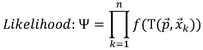
那么,最大化似然也就相当于最小化负对数-logΨ的似然:Then, maximizing the likelihood is equivalent to minimizing the likelihood of the negative log-logΨ:

以上公式求得最小化配准的误差。The above formula is calculated to minimize the registration error.
接下来使用牛顿法对

步骤302、当点云配准定位算法检测到车辆即将抵达地图边缘,即驶出隧道时,会通知定位系统隧道即将结束,并在点云概率地图结束后3秒内结束定位信息的输出。Step 302: When the point cloud registration and positioning algorithm detects that the vehicle is about to reach the edge of the map, that is, when it leaves the tunnel, it will notify the positioning system that the tunnel is about to end, and stop the output of positioning information within 3 seconds after the end of the point cloud probability map.
步骤四:不存在点云地图,使用路标基点定位算法进行车辆定位。Step 4: There is no point cloud map, use the road sign base point positioning algorithm to locate the vehicle.
车辆捕获当前时刻点云数据后,路标基点定位算法首先识别路标,然后计算两侧最近路标之间的距离差值,将路标距离差值与预先存储在车内的路标数据库对比后即可计算出当前车辆位置。这种定位方法同样能够实现快读准确的重定位。本发明即使在没有先验点云地图的场景下仍然可以保持一个较短的处理时间,也可以保证定位信息最少以10Hz的频率输出,满足一般自动驾驶车辆对定位周期的最低需求。After the vehicle captures the point cloud data at the current moment, the road sign base point positioning algorithm first identifies the road sign, then calculates the distance difference between the nearest road signs on both sides, and compares the distance difference between the road signs with the road sign database pre-stored in the vehicle to calculate Current vehicle location. This positioning method can also realize fast reading and accurate relocation. The present invention can still maintain a short processing time even in the scene without a priori point cloud map, and can also ensure that the positioning information is output at a frequency of at least 10 Hz, which meets the minimum requirements for the positioning cycle of general autonomous vehicles.
如图6所示,本发明使用路标基点定位算法对车辆定位,首先装备在车辆上的GPU计算平台接收雷达激光的点云数据,然后执行如下步骤:As shown in Figure 6, the present invention uses the road sign base point positioning algorithm to locate the vehicle. First, the GPU computing platform equipped on the vehicle receives the point cloud data of the radar laser, and then performs the following steps:
步骤401、对收到的每一帧点云进行处理,识别路标,具体流程如图7所示。Step 401: Process each received frame of point cloud to identify road signs. The specific process is shown in FIG. 7 .
(a)去除原始点云中远离点云集群的野点,利用体素网格滤波(Voxel GridFilter,VGF)下采样算法减少点云数量加快运算速度。VGF方法首先计算一个能够刚好包裹住该点云的立方体,然后根据设定的分辨率,将该大立方体分割成不同的小立方体。对于每一个小立方体内的点,计算它们的质心,并用该质心的坐标来近似该立方体内的若干点。(a) Remove the wild points far from the point cloud cluster in the original point cloud, and use the Voxel Grid Filter (VGF) downsampling algorithm to reduce the number of point clouds and speed up the operation. The VGF method first calculates a cube that can just wrap the point cloud, and then divides the large cube into different small cubes according to the set resolution. For each of the points within the small cube, calculate their centroid, and use the coordinates of the centroid to approximate the points within the cube.
(b)对下采样后得到的点云进行地面平面的拟合,如图8所示,具体为:(b) Fitting the ground plane to the point cloud obtained after downsampling, as shown in Figure 8, specifically:
先通过若干个最低高度点的平均值计算出最低点代表(Lowest PointRepresentative,LPR)的高度,选取和LPR高度差值在一定范围内的点纳入种子点集S∈R3,计算种子点的平均值
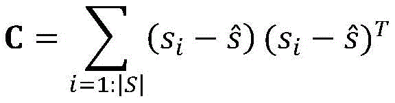
其中,|S|表示种子点集中种子点的数量,si表示第i个种子点的三维坐标。Among them, |S| represents the number of seed points in the seed point set, and si represents the three-dimensional coordinates of the ith seed point.
将C进行奇异值分解后得到三个奇异向量,这三个奇异向量描述了点集在三个主要方向的散布情况,垂直于平面的法向量n表示具有最小方差的方向,可以通过计算具有最小奇异值的奇异向量来求得,则平面的高度值d可通过下式计算:After singular value decomposition of C, three singular vectors are obtained. These three singular vectors describe the dispersion of the point set in three main directions. The normal vector n perpendicular to the plane represents the direction with the smallest variance, which can be calculated by calculating The singular vector of singular values can be obtained, then the height value d of the plane can be calculated by the following formula:
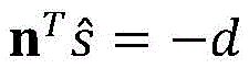
将与上述平面的投影距离小于一定阈值的点再次纳入种子点集,并重复上述过程即可连续求得地面高度,即地面所在的平面Z值。此处的阈值根据经验来设置。The points whose projection distance from the above plane is less than a certain threshold are included in the seed point set again, and the above process is repeated to continuously obtain the ground height, that is, the Z value of the plane where the ground is located. The threshold here is set empirically.
(c)将点云进一步通过直通滤波,直接过滤出距离地平面高度为1.5米至2.5米的点云,即路标所在的高度。(c) The point cloud is further filtered through through filtering, and the point cloud with a height of 1.5m to 2.5m from the ground plane is directly filtered, that is, the height of the road sign.
(d)创建点云的K维树(KD-tree)以便快速索引,设定半径阈值,将欧氏距离在半径内的点聚类成一个点云簇,划分聚类区域后标识该区域的中心位置和索引值。(d) Create a K-dimensional tree (KD-tree) of the point cloud for fast indexing, set a radius threshold, cluster the points with Euclidean distance within the radius into a point cloud cluster, and identify the area of the area after dividing the clustering area. Center position and index value.
(e)在每一个聚类区域内,使用随机抽样一致算法(RANSAC)来拟合横向的平面,判断聚类内所拟合的这些平面是否近似平行,如存在平面近似平行则计算出这些平面在法向上的差值,否则认为该聚类所对应的路标损坏,或者不是路标,放弃该聚类区域,不需要进一步计算。(e) In each cluster area, use random sampling consensus algorithm (RANSAC) to fit horizontal planes, and determine whether the fitted planes in the cluster are approximately parallel. If there are planes that are approximately parallel, calculate these planes. The difference in the normal direction, otherwise, it is considered that the road sign corresponding to the cluster is damaged, or it is not a road sign, and the cluster area is discarded, and no further calculation is required.
(f)将同一聚类内的相邻平面间的法向上的差值与布设路标的距离差值作对比,如果二者差值在误差范围内,近似相同,则认为该聚类为路标,输出该聚类的中心位置与路标类型,聚类的中心位置就是路标的坐标,路标类型是指当隧道内采用不同特征的路标时需要输出,如果采用相同路标,则可不输出路标类型;如果差值在误差范围之外,则认为该聚类不是路标,继续查找下一个聚类。(f) Compare the difference in the normal between adjacent planes in the same cluster with the distance difference between the road signs. If the difference between the two is within the error range and is approximately the same, the cluster is considered to be a road sign. Output the center position and road sign type of the cluster. The center position of the cluster is the coordinates of the road sign. The road sign type refers to the need to output when road signs with different characteristics are used in the tunnel. If the same road sign is used, the road sign type may not be output; If the value is outside the error range, the cluster is considered not to be a landmark, and the search for the next cluster continues.
(g)当本帧点云的所有聚类对比完成后,返回步骤a,等待新的点云信息开始下一个循环。(g) When all the clustering comparisons of the point cloud in this frame are completed, go back to step a and wait for the new point cloud information to start the next cycle.
步骤402、在得到路标的坐标后,首先通过路标间距确定车辆所处的里程段,本发明实施例中就是判断车辆是处于第几个470米中,计算左右两个相邻路标中心的纵向距离差值ΔD,并从里程段开始处依次遍历比对相邻路标的标准差值,找到差值与ΔD最相近的一组路标,作为此时识别到的路标。根据所识别的路标可以对车辆当前在隧道内的位置进行定位。Step 402: After obtaining the coordinates of the road signs, first determine the mileage segment where the vehicle is located by using the distance between the road signs. In the embodiment of the present invention, it is to determine which 470 meters the vehicle is in, and calculate the longitudinal distance between the centers of the left and right adjacent road signs. The difference value ΔD is traversed and compared with the standard deviation values of adjacent road signs from the beginning of the mileage segment, and a group of road signs with the difference value closest to ΔD is found as the road signs identified at this time. Based on the identified road signs, the current position of the vehicle in the tunnel can be located.
在通过以上计算可知目前识别到的路标的里程位置,通过路标与车辆的相对坐标可以进一步反推计算出车辆的当前里程位置和横向位置。组合同一时间的横纵向位置信息,随着车辆向前行驶,继续识别左右侧路标;本发明还对计算的车辆位置进行误差补偿,输出更加精确的车辆位置信息。The mileage position of the currently recognized road sign can be known through the above calculation, and the current mileage position and lateral position of the vehicle can be further calculated by inverse calculation through the relative coordinates of the road sign and the vehicle. Combine the horizontal and vertical position information at the same time, continue to identify the left and right road signs as the vehicle moves forward; the present invention also performs error compensation on the calculated vehicle position to output more accurate vehicle position information.
步骤3和步骤4的两种定位算法中的误差主要来源于每个计算循环中车辆的位移,因此本发明还进一步的通过车辆CAN总线,来获得当时的车速信息,对车速进行积分后得到计算耗时中的车辆位移,对所识别的车辆定位结果进行补偿以消除误差。The errors in the two positioning algorithms of step 3 and step 4 mainly come from the displacement of the vehicle in each calculation cycle, so the present invention further obtains the vehicle speed information at that time through the vehicle CAN bus, and obtains the calculation after integrating the vehicle speed. The time-consuming vehicle displacement is compensated for the identified vehicle positioning results to eliminate errors.
以上仅是本发明的一个实施方式,应当指出:对于本技术领域的普通技术人员来说,在不脱离本发明原理的前提下,还可以轻易做出若干改进和润饰,但这些改进和润饰也应视为本发明的保护范围。The above is only an embodiment of the present invention, it should be pointed out: for those skilled in the art, without departing from the principle of the present invention, several improvements and modifications can be easily made, but these improvements and modifications are also It should be regarded as the protection scope of the present invention.
Claims (6)
Priority Applications (1)
| Application Number | Priority Date | Filing Date | Title |
|---|---|---|---|
| CN201911046049.XA CN110618434B (en) | 2019-10-30 | 2019-10-30 | Tunnel positioning system based on laser radar and positioning method thereof |
Applications Claiming Priority (1)
| Application Number | Priority Date | Filing Date | Title |
|---|---|---|---|
| CN201911046049.XA CN110618434B (en) | 2019-10-30 | 2019-10-30 | Tunnel positioning system based on laser radar and positioning method thereof |
Publications (2)
| Publication Number | Publication Date |
|---|---|
| CN110618434A CN110618434A (en) | 2019-12-27 |
| CN110618434B true CN110618434B (en) | 2021-11-16 |
Family
ID=68927041
Family Applications (1)
| Application Number | Title | Priority Date | Filing Date |
|---|---|---|---|
| CN201911046049.XA Active CN110618434B (en) | 2019-10-30 | 2019-10-30 | Tunnel positioning system based on laser radar and positioning method thereof |
Country Status (1)
| Country | Link |
|---|---|
| CN (1) | CN110618434B (en) |
Cited By (1)
| Publication number | Priority date | Publication date | Assignee | Title |
|---|---|---|---|---|
| WO2025078129A1 (en) * | 2023-10-11 | 2025-04-17 | Valeo Detection Systems GmbH | Method and processor for recognizing a stationary traffic sign |
Families Citing this family (23)
| Publication number | Priority date | Publication date | Assignee | Title |
|---|---|---|---|---|
| CN113138594B (en) * | 2020-01-20 | 2024-04-19 | 北京四维图新科技股份有限公司 | Automatic driving method and device |
| CN110926383B (en) * | 2020-02-18 | 2020-05-19 | 长沙瑞感电子科技有限公司 | Millimeter wave sensor-based tunnel segment dislocation detection device and detection method |
| CN111429528A (en) * | 2020-04-07 | 2020-07-17 | 高深智图(广州)科技有限公司 | Large-scale distributed high-precision map data processing system |
| CN111812674B (en) * | 2020-06-08 | 2024-04-05 | 北京经纬恒润科技股份有限公司 | Laser radar simulation method and device |
| CN113866779B (en) * | 2020-06-30 | 2025-06-06 | 上海商汤智能科技有限公司 | Point cloud data fusion method, device, electronic device and storage medium |
| CN114063090B (en) | 2020-07-29 | 2025-05-09 | 北京图森未来科技有限公司 | A method and device for positioning a movable device and a movable device |
| CN114061570B (en) * | 2020-07-31 | 2025-04-04 | 希迪智驾科技股份有限公司 | Vehicle positioning method, device, computer equipment and storage medium |
| CN112132896B (en) * | 2020-09-16 | 2024-05-10 | 北京埃福瑞科技有限公司 | Method and system for detecting states of trackside equipment |
| CN112406964B (en) * | 2020-11-10 | 2022-12-02 | 北京埃福瑞科技有限公司 | Train positioning method and system |
| CN112925000B (en) * | 2021-01-25 | 2022-05-17 | 东南大学 | Vehicle localization method in tunnel environment based on visible light communication and inertial navigation |
| CN115047469A (en) * | 2021-03-09 | 2022-09-13 | 上海交通大学 | Underground engineering machinery positioning system and method based on laser reflector |
| CN113156455A (en) * | 2021-03-16 | 2021-07-23 | 武汉理工大学 | Vehicle positioning system, method, device and medium based on roadside multi-laser radar perception |
| CN113252042B (en) * | 2021-05-18 | 2023-06-13 | 杭州迦智科技有限公司 | Positioning method and device based on laser and UWB in tunnel |
| TWI807548B (en) * | 2021-10-18 | 2023-07-01 | 國立陽明交通大學 | Vehicular positioning method and system of utilizing repeated feature object, computer-readable medium |
| CN114155389A (en) * | 2021-11-15 | 2022-03-08 | 东风汽车集团股份有限公司 | Automatic driving vehicle positioning method and device |
| US12384404B2 (en) * | 2022-01-06 | 2025-08-12 | GM Global Technology Operations LLC | Motion monitor using lidar registration |
| CN114910928B (en) * | 2022-05-20 | 2024-12-27 | 山东高速建设管理集团有限公司 | Method and device for positioning vehicle in tunnel and storable medium |
| CN115031755B (en) * | 2022-06-13 | 2025-11-07 | 智道网联科技(北京)有限公司 | Automatic driving vehicle positioning method and device, electronic equipment and storage medium |
| CN115097466B (en) * | 2022-06-16 | 2025-05-13 | 酷哇科技有限公司 | Open road vehicle three-dimensional positioning system and method based on high-reflective road signs |
| CN115435770B (en) * | 2022-08-08 | 2024-09-10 | 重庆长安汽车股份有限公司 | Method for constructing tunnel road section map based on high-precision map |
| CN115311867B (en) * | 2022-10-11 | 2023-01-10 | 腾讯科技(深圳)有限公司 | Tunnel scene positioning method and device, computer equipment and storage medium |
| CN116609756B (en) * | 2023-04-13 | 2025-04-18 | 安徽宇锋智能科技有限公司 | An algorithm for eliminating interference from strongly reflective objects in 2D laser reflective column positioning |
| CN118189954B (en) * | 2024-03-06 | 2024-11-19 | 中铁长江交通设计集团有限公司 | High-precision positioning method, server, system and medium for rapid tunnel detection |
Citations (10)
| Publication number | Priority date | Publication date | Assignee | Title |
|---|---|---|---|---|
| CN102053249A (en) * | 2009-10-30 | 2011-05-11 | 吴立新 | Underground space high-precision positioning method based on laser scanning and sequence encoded graphics |
| CN102518028A (en) * | 2011-10-25 | 2012-06-27 | 中交第二公路勘察设计研究院有限公司 | Precise plane coordinate correction method in laser radar scanning measurement |
| CN105531601A (en) * | 2013-09-20 | 2016-04-27 | 卡特彼勒公司 | GPS |
| KR101754739B1 (en) * | 2016-12-26 | 2017-08-08 | 대한민국(방위사업청장) | Battlefield situation placement device and method thereof |
| CN107918940A (en) * | 2017-10-09 | 2018-04-17 | 北京奇虎科技有限公司 | External equipment recognition methods and device, identity device, external equipment, system |
| CN109085821A (en) * | 2018-06-22 | 2018-12-25 | 苏州上善知源汽车电子有限公司 | Automatic driving vehicle localization method |
| CN110196429A (en) * | 2018-04-02 | 2019-09-03 | 北京航空航天大学 | Vehicle target recognition methods, storage medium, processor and system |
| CN110244321A (en) * | 2019-04-22 | 2019-09-17 | 武汉理工大学 | A kind of road based on three-dimensional laser radar can traffic areas detection method |
| CN110376605A (en) * | 2018-09-18 | 2019-10-25 | 北京京东尚科信息技术有限公司 | Map constructing method, air navigation aid and device |
| CN110389590A (en) * | 2019-08-19 | 2019-10-29 | 杭州电子科技大学 | A kind of AGV positioning system and method merging 2D environmental map and sparse artificial landmark |
Family Cites Families (6)
| Publication number | Priority date | Publication date | Assignee | Title |
|---|---|---|---|---|
| US7629899B2 (en) * | 1997-10-22 | 2009-12-08 | Intelligent Technologies International, Inc. | Vehicular communication arrangement and method |
| US6720920B2 (en) * | 1997-10-22 | 2004-04-13 | Intelligent Technologies International Inc. | Method and arrangement for communicating between vehicles |
| US6768944B2 (en) * | 2002-04-09 | 2004-07-27 | Intelligent Technologies International, Inc. | Method and system for controlling a vehicle |
| CN105203551A (en) * | 2015-09-11 | 2015-12-30 | 尹栋 | Car-mounted laser radar tunnel detection system, autonomous positioning method based on tunnel detection system and tunnel hazard detection method |
| CN106087621B (en) * | 2016-05-31 | 2017-11-24 | 中铁第四勘察设计院集团有限公司 | A kind of Existing Railway Line repetition measurement method based on mobile lidar technology |
| US20170374342A1 (en) * | 2016-06-24 | 2017-12-28 | Isee, Inc. | Laser-enhanced visual simultaneous localization and mapping (slam) for mobile devices |
-
2019
- 2019-10-30 CN CN201911046049.XA patent/CN110618434B/en active Active
Patent Citations (10)
| Publication number | Priority date | Publication date | Assignee | Title |
|---|---|---|---|---|
| CN102053249A (en) * | 2009-10-30 | 2011-05-11 | 吴立新 | Underground space high-precision positioning method based on laser scanning and sequence encoded graphics |
| CN102518028A (en) * | 2011-10-25 | 2012-06-27 | 中交第二公路勘察设计研究院有限公司 | Precise plane coordinate correction method in laser radar scanning measurement |
| CN105531601A (en) * | 2013-09-20 | 2016-04-27 | 卡特彼勒公司 | GPS |
| KR101754739B1 (en) * | 2016-12-26 | 2017-08-08 | 대한민국(방위사업청장) | Battlefield situation placement device and method thereof |
| CN107918940A (en) * | 2017-10-09 | 2018-04-17 | 北京奇虎科技有限公司 | External equipment recognition methods and device, identity device, external equipment, system |
| CN110196429A (en) * | 2018-04-02 | 2019-09-03 | 北京航空航天大学 | Vehicle target recognition methods, storage medium, processor and system |
| CN109085821A (en) * | 2018-06-22 | 2018-12-25 | 苏州上善知源汽车电子有限公司 | Automatic driving vehicle localization method |
| CN110376605A (en) * | 2018-09-18 | 2019-10-25 | 北京京东尚科信息技术有限公司 | Map constructing method, air navigation aid and device |
| CN110244321A (en) * | 2019-04-22 | 2019-09-17 | 武汉理工大学 | A kind of road based on three-dimensional laser radar can traffic areas detection method |
| CN110389590A (en) * | 2019-08-19 | 2019-10-29 | 杭州电子科技大学 | A kind of AGV positioning system and method merging 2D environmental map and sparse artificial landmark |
Non-Patent Citations (2)
| Title |
|---|
| 《基于无人机航拍序列的建筑三维模型重建》;黄佳彪等;《湖南工业大学学报》;20170930;第31卷(第5期);第6-10页 * |
| 《托卡马克部件转运车的定位与导航方法研究》;石飞;《中国优秀硕士学位论文全文数据库 信息科技辑》;20150615;第36-39页 * |
Cited By (1)
| Publication number | Priority date | Publication date | Assignee | Title |
|---|---|---|---|---|
| WO2025078129A1 (en) * | 2023-10-11 | 2025-04-17 | Valeo Detection Systems GmbH | Method and processor for recognizing a stationary traffic sign |
Also Published As
| Publication number | Publication date |
|---|---|
| CN110618434A (en) | 2019-12-27 |
Similar Documents
| Publication | Publication Date | Title |
|---|---|---|
| CN110618434B (en) | Tunnel positioning system based on laser radar and positioning method thereof | |
| CN113030997B (en) | Method for detecting travelable area of open-pit mine area based on laser radar | |
| CN106842231B (en) | A kind of road edge identification and tracking | |
| CN110781827A (en) | A road edge detection system and method based on lidar and fan-shaped space segmentation | |
| CN110781891B (en) | Method for identifying vehicle travelable area based on laser radar sensor | |
| CN104950313B (en) | Extract and identification of road grade method on a kind of road surface | |
| CN103226833B (en) | A kind of point cloud data segmentation method based on three-dimensional laser radar | |
| CN105667518B (en) | The method and device of lane detection | |
| CN109031346A (en) | A kind of periphery parking position aided detection method based on 3D laser radar | |
| CN105404844B (en) | A kind of Method for Road Boundary Detection based on multi-line laser radar | |
| CN114877838B (en) | Road geometric feature detection method based on vehicle-mounted laser scanning system | |
| WO2021097618A1 (en) | Point cloud segmentation method and system, and computer storage medium | |
| WO2024120269A1 (en) | Position recognition method for fusing point cloud map, motion model and local feature | |
| CN108802785A (en) | Vehicle method for self-locating based on High-precision Vector map and monocular vision sensor | |
| CN116524219A (en) | Barrier detection method based on laser radar point cloud clustering | |
| US12366660B2 (en) | System and method for detecting road intersection on point cloud height map | |
| CN114089376A (en) | Single laser radar-based negative obstacle detection method | |
| CN115097466B (en) | Open road vehicle three-dimensional positioning system and method based on high-reflective road signs | |
| CN117078870A (en) | Three-dimensional reconstruction method of road environment integrating high-precision map and laser sparse point cloud | |
| CN116299313A (en) | Laser radar-based intelligent vehicle passable area detection method | |
| IL323610A (en) | System and method for localizing an autonomous vehicle | |
| CN113012206B (en) | Airborne and vehicle-mounted LiDAR point cloud registration method considering eave characteristics | |
| CN113721254A (en) | Vehicle positioning method based on road fingerprint space incidence matrix | |
| CN117029870A (en) | A laser odometer based on road point cloud | |
| CN119600550B (en) | Traffic target monitoring and tracking method based on monocular vision daytime scene reconstruction |
Legal Events
| Date | Code | Title | Description |
|---|---|---|---|
| PB01 | Publication | ||
| PB01 | Publication | ||
| SE01 | Entry into force of request for substantive examination | ||
| SE01 | Entry into force of request for substantive examination | ||
| GR01 | Patent grant | ||
| GR01 | Patent grant |