CN110549539B - Method for producing a guide rod for a pump - Google Patents
Method for producing a guide rod for a pump Download PDFInfo
- Publication number
- CN110549539B CN110549539B CN201910460765.6A CN201910460765A CN110549539B CN 110549539 B CN110549539 B CN 110549539B CN 201910460765 A CN201910460765 A CN 201910460765A CN 110549539 B CN110549539 B CN 110549539B
- Authority
- CN
- China
- Prior art keywords
- rod
- head
- membrane
- pump
- tool
- Prior art date
- Legal status (The legal status is an assumption and is not a legal conclusion. Google has not performed a legal analysis and makes no representation as to the accuracy of the status listed.)
- Active
Links
Images


Classifications
-
- B—PERFORMING OPERATIONS; TRANSPORTING
- B05—SPRAYING OR ATOMISING IN GENERAL; APPLYING FLUENT MATERIALS TO SURFACES, IN GENERAL
- B05B—SPRAYING APPARATUS; ATOMISING APPARATUS; NOZZLES
- B05B11/00—Single-unit hand-held apparatus in which flow of contents is produced by the muscular force of the operator at the moment of use
- B05B11/01—Single-unit hand-held apparatus in which flow of contents is produced by the muscular force of the operator at the moment of use characterised by the means producing the flow
- B05B11/04—Deformable containers producing the flow, e.g. squeeze bottles
- B05B11/042—Deformable containers producing the flow, e.g. squeeze bottles the spray being effected by a gas or vapour flow in the nozzle, spray head, outlet or dip tube
-
- B—PERFORMING OPERATIONS; TRANSPORTING
- B05—SPRAYING OR ATOMISING IN GENERAL; APPLYING FLUENT MATERIALS TO SURFACES, IN GENERAL
- B05B—SPRAYING APPARATUS; ATOMISING APPARATUS; NOZZLES
- B05B11/00—Single-unit hand-held apparatus in which flow of contents is produced by the muscular force of the operator at the moment of use
- B05B11/01—Single-unit hand-held apparatus in which flow of contents is produced by the muscular force of the operator at the moment of use characterised by the means producing the flow
- B05B11/10—Pump arrangements for transferring the contents from the container to a pump chamber by a sucking effect and forcing the contents out through the dispensing nozzle
- B05B11/1028—Pumps having a pumping chamber with a deformable wall
-
- B—PERFORMING OPERATIONS; TRANSPORTING
- B05—SPRAYING OR ATOMISING IN GENERAL; APPLYING FLUENT MATERIALS TO SURFACES, IN GENERAL
- B05B—SPRAYING APPARATUS; ATOMISING APPARATUS; NOZZLES
- B05B15/00—Details of spraying plant or spraying apparatus not otherwise provided for; Accessories
- B05B15/30—Dip tubes
-
- B—PERFORMING OPERATIONS; TRANSPORTING
- B29—WORKING OF PLASTICS; WORKING OF SUBSTANCES IN A PLASTIC STATE IN GENERAL
- B29C—SHAPING OR JOINING OF PLASTICS; SHAPING OF MATERIAL IN A PLASTIC STATE, NOT OTHERWISE PROVIDED FOR; AFTER-TREATMENT OF THE SHAPED PRODUCTS, e.g. REPAIRING
- B29C43/00—Compression moulding, i.e. applying external pressure to flow the moulding material; Apparatus therefor
- B29C43/02—Compression moulding, i.e. applying external pressure to flow the moulding material; Apparatus therefor of articles of definite length, i.e. discrete articles
- B29C43/021—Compression moulding, i.e. applying external pressure to flow the moulding material; Apparatus therefor of articles of definite length, i.e. discrete articles characterised by the shape of the surface
-
- B—PERFORMING OPERATIONS; TRANSPORTING
- B29—WORKING OF PLASTICS; WORKING OF SUBSTANCES IN A PLASTIC STATE IN GENERAL
- B29C—SHAPING OR JOINING OF PLASTICS; SHAPING OF MATERIAL IN A PLASTIC STATE, NOT OTHERWISE PROVIDED FOR; AFTER-TREATMENT OF THE SHAPED PRODUCTS, e.g. REPAIRING
- B29C43/00—Compression moulding, i.e. applying external pressure to flow the moulding material; Apparatus therefor
- B29C43/02—Compression moulding, i.e. applying external pressure to flow the moulding material; Apparatus therefor of articles of definite length, i.e. discrete articles
- B29C43/027—Compression moulding, i.e. applying external pressure to flow the moulding material; Apparatus therefor of articles of definite length, i.e. discrete articles having an axis of symmetry
-
- B—PERFORMING OPERATIONS; TRANSPORTING
- B29—WORKING OF PLASTICS; WORKING OF SUBSTANCES IN A PLASTIC STATE IN GENERAL
- B29C—SHAPING OR JOINING OF PLASTICS; SHAPING OF MATERIAL IN A PLASTIC STATE, NOT OTHERWISE PROVIDED FOR; AFTER-TREATMENT OF THE SHAPED PRODUCTS, e.g. REPAIRING
- B29C45/00—Injection moulding, i.e. forcing the required volume of moulding material through a nozzle into a closed mould; Apparatus therefor
- B29C45/0053—Injection moulding, i.e. forcing the required volume of moulding material through a nozzle into a closed mould; Apparatus therefor combined with a final operation, e.g. shaping
- B29C45/0055—Shaping
-
- B—PERFORMING OPERATIONS; TRANSPORTING
- B29—WORKING OF PLASTICS; WORKING OF SUBSTANCES IN A PLASTIC STATE IN GENERAL
- B29C—SHAPING OR JOINING OF PLASTICS; SHAPING OF MATERIAL IN A PLASTIC STATE, NOT OTHERWISE PROVIDED FOR; AFTER-TREATMENT OF THE SHAPED PRODUCTS, e.g. REPAIRING
- B29C45/00—Injection moulding, i.e. forcing the required volume of moulding material through a nozzle into a closed mould; Apparatus therefor
- B29C45/17—Component parts, details or accessories; Auxiliary operations
- B29C45/26—Moulds
-
- B—PERFORMING OPERATIONS; TRANSPORTING
- B05—SPRAYING OR ATOMISING IN GENERAL; APPLYING FLUENT MATERIALS TO SURFACES, IN GENERAL
- B05B—SPRAYING APPARATUS; ATOMISING APPARATUS; NOZZLES
- B05B11/00—Single-unit hand-held apparatus in which flow of contents is produced by the muscular force of the operator at the moment of use
- B05B11/01—Single-unit hand-held apparatus in which flow of contents is produced by the muscular force of the operator at the moment of use characterised by the means producing the flow
- B05B11/04—Deformable containers producing the flow, e.g. squeeze bottles
- B05B11/048—Deformable containers producing the flow, e.g. squeeze bottles characterised by the container, e.g. this latter being surrounded by an enclosure, or the means for deforming it
-
- B—PERFORMING OPERATIONS; TRANSPORTING
- B05—SPRAYING OR ATOMISING IN GENERAL; APPLYING FLUENT MATERIALS TO SURFACES, IN GENERAL
- B05B—SPRAYING APPARATUS; ATOMISING APPARATUS; NOZZLES
- B05B9/00—Spraying apparatus for discharge of liquids or other fluent material, without essentially mixing with gas or vapour
- B05B9/03—Spraying apparatus for discharge of liquids or other fluent material, without essentially mixing with gas or vapour characterised by means for supplying liquid or other fluent material
- B05B9/04—Spraying apparatus for discharge of liquids or other fluent material, without essentially mixing with gas or vapour characterised by means for supplying liquid or other fluent material with pressurised or compressible container; with pump
- B05B9/047—Spraying apparatus for discharge of liquids or other fluent material, without essentially mixing with gas or vapour characterised by means for supplying liquid or other fluent material with pressurised or compressible container; with pump supply being effected by follower in container, e.g. membrane or floating piston, or by deformation of container
-
- B—PERFORMING OPERATIONS; TRANSPORTING
- B29—WORKING OF PLASTICS; WORKING OF SUBSTANCES IN A PLASTIC STATE IN GENERAL
- B29C—SHAPING OR JOINING OF PLASTICS; SHAPING OF MATERIAL IN A PLASTIC STATE, NOT OTHERWISE PROVIDED FOR; AFTER-TREATMENT OF THE SHAPED PRODUCTS, e.g. REPAIRING
- B29C43/00—Compression moulding, i.e. applying external pressure to flow the moulding material; Apparatus therefor
- B29C43/02—Compression moulding, i.e. applying external pressure to flow the moulding material; Apparatus therefor of articles of definite length, i.e. discrete articles
- B29C43/021—Compression moulding, i.e. applying external pressure to flow the moulding material; Apparatus therefor of articles of definite length, i.e. discrete articles characterised by the shape of the surface
- B29C2043/026—Compression moulding, i.e. applying external pressure to flow the moulding material; Apparatus therefor of articles of definite length, i.e. discrete articles characterised by the shape of the surface having functional projections, e.g. fasteners
-
- B—PERFORMING OPERATIONS; TRANSPORTING
- B29—WORKING OF PLASTICS; WORKING OF SUBSTANCES IN A PLASTIC STATE IN GENERAL
- B29C—SHAPING OR JOINING OF PLASTICS; SHAPING OF MATERIAL IN A PLASTIC STATE, NOT OTHERWISE PROVIDED FOR; AFTER-TREATMENT OF THE SHAPED PRODUCTS, e.g. REPAIRING
- B29C43/00—Compression moulding, i.e. applying external pressure to flow the moulding material; Apparatus therefor
- B29C43/02—Compression moulding, i.e. applying external pressure to flow the moulding material; Apparatus therefor of articles of definite length, i.e. discrete articles
- B29C43/027—Compression moulding, i.e. applying external pressure to flow the moulding material; Apparatus therefor of articles of definite length, i.e. discrete articles having an axis of symmetry
- B29C2043/029—Compression moulding, i.e. applying external pressure to flow the moulding material; Apparatus therefor of articles of definite length, i.e. discrete articles having an axis of symmetry using axial compression along a longitudinal axis
-
- B—PERFORMING OPERATIONS; TRANSPORTING
- B29—WORKING OF PLASTICS; WORKING OF SUBSTANCES IN A PLASTIC STATE IN GENERAL
- B29C—SHAPING OR JOINING OF PLASTICS; SHAPING OF MATERIAL IN A PLASTIC STATE, NOT OTHERWISE PROVIDED FOR; AFTER-TREATMENT OF THE SHAPED PRODUCTS, e.g. REPAIRING
- B29C43/00—Compression moulding, i.e. applying external pressure to flow the moulding material; Apparatus therefor
- B29C43/32—Component parts, details or accessories; Auxiliary operations
- B29C43/52—Heating or cooling
- B29C2043/525—Heating or cooling at predetermined points for local melting, curing or bonding
-
- B—PERFORMING OPERATIONS; TRANSPORTING
- B29—WORKING OF PLASTICS; WORKING OF SUBSTANCES IN A PLASTIC STATE IN GENERAL
- B29C—SHAPING OR JOINING OF PLASTICS; SHAPING OF MATERIAL IN A PLASTIC STATE, NOT OTHERWISE PROVIDED FOR; AFTER-TREATMENT OF THE SHAPED PRODUCTS, e.g. REPAIRING
- B29C45/00—Injection moulding, i.e. forcing the required volume of moulding material through a nozzle into a closed mould; Apparatus therefor
- B29C45/0025—Preventing defects on the moulded article, e.g. weld lines, shrinkage marks
- B29C2045/0037—Moulding articles or parts thereof without parting line
-
- B—PERFORMING OPERATIONS; TRANSPORTING
- B29—WORKING OF PLASTICS; WORKING OF SUBSTANCES IN A PLASTIC STATE IN GENERAL
- B29C—SHAPING OR JOINING OF PLASTICS; SHAPING OF MATERIAL IN A PLASTIC STATE, NOT OTHERWISE PROVIDED FOR; AFTER-TREATMENT OF THE SHAPED PRODUCTS, e.g. REPAIRING
- B29C45/00—Injection moulding, i.e. forcing the required volume of moulding material through a nozzle into a closed mould; Apparatus therefor
- B29C45/0053—Injection moulding, i.e. forcing the required volume of moulding material through a nozzle into a closed mould; Apparatus therefor combined with a final operation, e.g. shaping
- B29C45/0055—Shaping
- B29C2045/0058—Shaping removing material
-
- B—PERFORMING OPERATIONS; TRANSPORTING
- B29—WORKING OF PLASTICS; WORKING OF SUBSTANCES IN A PLASTIC STATE IN GENERAL
- B29C—SHAPING OR JOINING OF PLASTICS; SHAPING OF MATERIAL IN A PLASTIC STATE, NOT OTHERWISE PROVIDED FOR; AFTER-TREATMENT OF THE SHAPED PRODUCTS, e.g. REPAIRING
- B29C2793/00—Shaping techniques involving a cutting or machining operation
- B29C2793/0054—Shaping techniques involving a cutting or machining operation partially cutting through the material
-
- B—PERFORMING OPERATIONS; TRANSPORTING
- B29—WORKING OF PLASTICS; WORKING OF SUBSTANCES IN A PLASTIC STATE IN GENERAL
- B29C—SHAPING OR JOINING OF PLASTICS; SHAPING OF MATERIAL IN A PLASTIC STATE, NOT OTHERWISE PROVIDED FOR; AFTER-TREATMENT OF THE SHAPED PRODUCTS, e.g. REPAIRING
- B29C2793/00—Shaping techniques involving a cutting or machining operation
- B29C2793/0063—Cutting longitudinally
-
- B—PERFORMING OPERATIONS; TRANSPORTING
- B29—WORKING OF PLASTICS; WORKING OF SUBSTANCES IN A PLASTIC STATE IN GENERAL
- B29C—SHAPING OR JOINING OF PLASTICS; SHAPING OF MATERIAL IN A PLASTIC STATE, NOT OTHERWISE PROVIDED FOR; AFTER-TREATMENT OF THE SHAPED PRODUCTS, e.g. REPAIRING
- B29C2793/00—Shaping techniques involving a cutting or machining operation
- B29C2793/009—Shaping techniques involving a cutting or machining operation after shaping
-
- B—PERFORMING OPERATIONS; TRANSPORTING
- B29—WORKING OF PLASTICS; WORKING OF SUBSTANCES IN A PLASTIC STATE IN GENERAL
- B29C—SHAPING OR JOINING OF PLASTICS; SHAPING OF MATERIAL IN A PLASTIC STATE, NOT OTHERWISE PROVIDED FOR; AFTER-TREATMENT OF THE SHAPED PRODUCTS, e.g. REPAIRING
- B29C45/00—Injection moulding, i.e. forcing the required volume of moulding material through a nozzle into a closed mould; Apparatus therefor
- B29C45/14—Injection moulding, i.e. forcing the required volume of moulding material through a nozzle into a closed mould; Apparatus therefor incorporating preformed parts or layers, e.g. injection moulding around inserts or for coating articles
-
- B—PERFORMING OPERATIONS; TRANSPORTING
- B29—WORKING OF PLASTICS; WORKING OF SUBSTANCES IN A PLASTIC STATE IN GENERAL
- B29C—SHAPING OR JOINING OF PLASTICS; SHAPING OF MATERIAL IN A PLASTIC STATE, NOT OTHERWISE PROVIDED FOR; AFTER-TREATMENT OF THE SHAPED PRODUCTS, e.g. REPAIRING
- B29C45/00—Injection moulding, i.e. forcing the required volume of moulding material through a nozzle into a closed mould; Apparatus therefor
- B29C45/17—Component parts, details or accessories; Auxiliary operations
- B29C45/26—Moulds
- B29C45/261—Moulds having tubular mould cavities
-
- B—PERFORMING OPERATIONS; TRANSPORTING
- B29—WORKING OF PLASTICS; WORKING OF SUBSTANCES IN A PLASTIC STATE IN GENERAL
- B29L—INDEXING SCHEME ASSOCIATED WITH SUBCLASS B29C, RELATING TO PARTICULAR ARTICLES
- B29L2031/00—Other particular articles
- B29L2031/06—Rods, e.g. connecting rods, rails, stakes
-
- B—PERFORMING OPERATIONS; TRANSPORTING
- B29—WORKING OF PLASTICS; WORKING OF SUBSTANCES IN A PLASTIC STATE IN GENERAL
- B29L—INDEXING SCHEME ASSOCIATED WITH SUBCLASS B29C, RELATING TO PARTICULAR ARTICLES
- B29L2031/00—Other particular articles
- B29L2031/56—Stoppers or lids for bottles, jars, or the like, e.g. closures
-
- B—PERFORMING OPERATIONS; TRANSPORTING
- B29—WORKING OF PLASTICS; WORKING OF SUBSTANCES IN A PLASTIC STATE IN GENERAL
- B29L—INDEXING SCHEME ASSOCIATED WITH SUBCLASS B29C, RELATING TO PARTICULAR ARTICLES
- B29L2031/00—Other particular articles
- B29L2031/748—Machines or parts thereof not otherwise provided for
- B29L2031/7496—Pumps
Landscapes
- Engineering & Computer Science (AREA)
- Mechanical Engineering (AREA)
- Manufacturing & Machinery (AREA)
- Moulds For Moulding Plastics Or The Like (AREA)
- Closures For Containers (AREA)
- Reciprocating Pumps (AREA)
Abstract
Description
技术领域technical field
本发明涉及对用于泵的引导杆进行制造的方法,该泵用于分配流体产品,特别是用在化妆品小瓶中。The invention relates to a method of manufacturing a guide rod for a pump for dispensing fluid products, in particular for use in cosmetic vials.
某些化妆品小瓶设置有泵,该泵被构造成抽吸容纳在小瓶的容器中的化妆品,以便例如通过喷嘴或通过简单的开口来分配化妆品。因此,可从小瓶中抽取出或喷出产品以便允许敷用该产品。泵通常通过按钮来致动,用户在该按钮上施加压力以触发泵的功能。泵特别地包括泵送室,该泵送室的体积变化以使得当体积增加时可以通过入口孔将产品抽吸到泵送室中,然后当泵送室的体积减小时可以通过出口孔将产品排出到泵送室外。产品离开泵送室进入到分配导管中,该分配导管将产品引导到通常被布置在按钮上的开口或喷嘴。Certain cosmetic vials are provided with a pump configured to pump the cosmetic contained in the container of the vial in order to dispense the cosmetic, for example through a nozzle or through a simple opening. Thus, the product can be withdrawn or sprayed from the vial to allow application of the product. The pump is usually actuated by a button on which the user applies pressure to trigger the function of the pump. The pump specifically includes a pumping chamber whose volume changes so that product can be drawn into the pumping chamber through the inlet orifice as the volume increases, and then through the outlet orifice as the volume of the pumping chamber decreases. Discharge to pumping chamber. The product exits the pumping chamber into a dispensing conduit which directs the product to an opening or nozzle, usually arranged on a button.
不同类型的泵、特别是其泵送室主要由柔性膜限定的泵是已知的。泵送室的体积通过使膜变形来控制。在膜的未变形构型中,泵送室的体积最大。当膜变形时,泵送室的体积优选地减小到非常小的体积,使得最大量的产品离开泵送室。Different types of pumps are known, in particular pumps whose pumping chamber is mainly defined by a flexible membrane. The volume of the pumping chamber is controlled by deforming the membrane. In the undeformed configuration of the membrane, the volume of the pumping chamber is at a maximum. When the membrane is deformed, the volume of the pumping chamber preferably decreases to a very small volume so that the maximum amount of product leaves the pumping chamber.
泵的元件优选地由塑料材料设计和制成。The elements of the pump are preferably designed and made of plastic material.
能变形的膜由一体件制成,引导该膜变形以确保最佳折叠,而不需要将膜限制在隔室中或使膜具有复杂的形状。为此,泵包括穿过膜的引导杆,当膜受到所述变形时,膜沿着杆滑动,使得膜相对于杆被径向地保持,并且膜仅围绕杆的轴线移动。因此,引导杆使得可以在膜受到变形时引导膜,并可以避免膜以有损于泵的方式被折叠。The deformable membrane is made in one piece, and deformation of the membrane is guided to ensure optimal folding without confining the membrane in compartments or giving the membrane a complex shape. For this purpose, the pump comprises a guide rod passing through the membrane, along which the membrane slides when the membrane is subjected to said deformation, so that the membrane is held radially relative to the rod and the membrane only moves around the axis of the rod. Thus, the guide rods make it possible to guide the membrane when it is subjected to deformation and to avoid the membrane being folded in a way that would be detrimental to the pump.
该引导杆包括相对于杆的本体具有边缘的引导头部,膜在杆的本体上滑动。该头部用作膜的高的抵接部。The guide rod comprises a guide head having an edge relative to the body of the rod on which the membrane slides. The head serves as a high abutment for the membrane.
杆的基部通常连接到膜支撑在其上的支撑件上。The base of the rod is usually connected to a support on which the membrane rests.
背景技术Background technique
杆/支撑件组件通过塑料注射而获得,其中,模具包括两个移动隔室,这两个隔室在杆的两侧上并且特别地形成引导杆的头部的边缘。这样的模具在现有技术中是已知的。The rod/support assembly is obtained by plastic injection, wherein the mold comprises two mobile compartments on both sides of the rod and in particular forms the edges guiding the head of the rod. Such molds are known in the prior art.
在脱模期间,杆不能在一个单独的板中脱模。实际上,头部的边缘使脱模变得不可能。因此,模具包括两个隔室,这两个隔室相对于杆的轴线横向地拆卸,以释放杆和杆的头部。因此,脱模后的杆包括接合平面,该接合平面在整个长度上延伸,位于两个隔室之间的接合部处。该接合平面是线,该接合平面的径向厚度可达数百毫米,这足以以损坏的方式恶化柔性膜与引导杆的连接的密封。During demoulding, the rods cannot be demolded in a single plate. In fact, the edge of the head makes demoulding impossible. Thus, the mold comprises two compartments that are disassembled transversely with respect to the axis of the rod to release the rod and the head of the rod. Thus, the stripped rod comprises a joint plane extending over the entire length at the joint between the two compartments. This joint plane is a line, the radial thickness of which can reach several hundred millimeters, which is sufficient to deteriorate in a damaging manner the sealing of the connection of the flexible membrane to the guide rod.
另一方面,设置有移动隔室的模具难以制造并且是昂贵的。On the other hand, molds provided with moving compartments are difficult and expensive to manufacture.
本发明的目的在于通过简化模制部件(即,杆)并通过在第二步骤期间对模制部件进行重新加工来改进制造方法。The object of the invention is to improve the manufacturing method by simplifying the molded part, ie the rod, and by reworking the molded part during the second step.
发明内容Contents of the invention
本发明的目的是通过对用于分配流体产品的泵的引导杆进行制造的方法来克服上述不同的缺点,所述杆包括圆柱形本体,圆柱形本体的顶部设有头部。The object of the present invention is to overcome the various disadvantages mentioned above by a method of manufacturing a guide rod for pumps for dispensing fluid products, said rod comprising a cylindrical body topped with a head.
该制造方法的特征主要在于,该制造方法包括以下步骤:The manufacturing method is mainly characterized in that the manufacturing method comprises the following steps:
-塑料注射模制步骤,以形成圆柱形杆;- a plastic injection molding step to form a cylindrical rod;
-校正杆的上端部的形状的步骤,以便通过在头部与杆的本体之间的接合部的水平处产生肩部而形成所述头部。- a step of correcting the shape of the upper end of the rod so as to form said head by creating a shoulder at the level of the junction between the head and the body of the rod.
有利地,塑料注射由单次注射组成。Advantageously, the plastic injection consists of a single shot.
有利地,塑料注射通过具有单个板的模具进行。这样的模具不包括隔室。Advantageously, plastic injection takes place through a mold with a single plate. Such molds do not include compartments.
有利地,杆的脱模在单次操作中进行。因此,诸如隔室的模制部分的相对于杆的轴线的横向移动不是必须的。Advantageously, the demoulding of the rod takes place in a single operation. Thus, no lateral movement of the molded part, such as the compartment, relative to the axis of the rod is necessary.
本发明的主要思想在于模制没有保持型头部的圆柱形的引导杆。因此,杆的上端部具有圆柱形几何形状,使得可以使用没有隔室的模具容易地脱模,其中,一个单独的板专用于杆的模制。这样的模具成本较低,具有真正的经济优势。The main idea of the invention is to mold a cylindrical guide rod without a retention profile head. Thus, the upper end of the rod has a cylindrical geometry that allows easy demoulding using a mold without compartments, where a separate plate is dedicated to the molding of the rod. Such molds cost less and have real economic advantages.
因为杆不再具有任何接合平面,所以不再存在损坏柔性膜与引导杆的连接的密封的任何风险。因此,泵的功能得到改善。Since the rod no longer has any joint planes, there is no longer any risk of damaging the seal of the connection of the flexible membrane to the guide rod. Thus, the function of the pump is improved.
此外,杆的头部将在该随后的校正形状的步骤期间形成。该形状校正步骤是在没有添加任何材料的情况下进行的。杆的上端部自身变形并成为头部。Furthermore, the head of the rod will be formed during this subsequent step of correcting the shape. This shape correction step is performed without adding any material. The upper end of the rod deforms itself and becomes the head.
根据第一种可能的构型,杆的头部的形状是在形状校正步骤期间通过热镦粗制成的。According to a first possible configuration, the shape of the head of the rod is produced by thermal upsetting during a shape correction step.
该形状校正步骤包括对杆的上端部进行加热直到塑料材料熔化的阶段,以及之后的将熔化的材料推回的阶段。This shape correction step comprises a stage of heating the upper end of the rod until the plastic material melts, followed by a stage of pushing back the melted material.
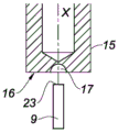
在通过镦粗校正形状的步骤期间,杆的上端部被放置成与具有中心轴线X的镦粗工具的加热表面发生接触,所述杆被布置在该轴线X的延伸中。During the step of correcting the shape by upsetting, the upper end of the rod is placed in contact with the heated surface of the upsetting tool having a central axis X, in the extension of which axis X the rod is arranged.
该加热表面是平坦的。The heating surface is flat.
该加热表面可具有加热腔,杆的上端部插入该加热腔中。The heating surface may have a heating cavity into which the upper end of the rod is inserted.
优选地,所述腔具有半球形形状以形成具有半球形外观的头部。从头部相对于本体具有边缘或肩部时起,可以考虑任何其他的头部形状,以便随后能够保持能变形的膜。Preferably, the cavity has a hemispherical shape to form a head having a hemispherical appearance. From the moment the head has an edge or a shoulder relative to the body, any other head shape is conceivable in order to be able to then hold the deformable membrane.
在推回阶段期间,无论加热表面的轮廓如何,镦粗工具均在杆的方向上沿着轴线X平移移动,以便在熔化的杆头部上施加压力,该压力导致熔化的材料在镦粗工具的移动方向上沿着杆的本体移动,以便在头部与杆的本体之间形成肩部。During the push-back phase, regardless of the profile of the heating surface, the upsetting tool is moved in translation in the direction of the rod along the axis X in order to exert pressure on the molten rod head, which causes the molten material to flow in the direction of the upsetting tool along the body of the rod in the direction of movement so as to form a shoulder between the head and the body of the rod.
可选地,杆的本体被夹在夹钳中,并且杆的上端部被推回,直到形成中的头部的下部面被压在夹钳的平坦的上部面上,使得头部的下部面是平坦的。该头部的下部面形成所述肩部。Alternatively, the body of the rod is clamped in the clamp and the upper end of the rod is pushed back until the lower face of the forming head is pressed against the flat upper face of the clamp such that the lower face of the head is flat. The lower face of the head forms said shoulders.
根据第二种可能的构型,杆的头部的形状是在形状校正步骤期间通过对杆的上端部的材料进行冷镦粗而制成的。According to a second possible configuration, the shape of the head of the rod is produced during a shape correction step by cold heading the material of the upper end of the rod.
杆的上端部与镦粗工具相对布置,该镦粗工具由比塑料耐抗性更高的金属类型的材料设计和制成,并且镦粗工具的与杆的上端部相对的表面具有锋利的环形边缘以及围绕环形边缘的环形凹部,该环形边缘的直径小于杆的公称直径,镦粗工具具有中心轴线X,所述杆被布置在该轴线X的延伸中。The upper end of the rod is arranged opposite the upsetting tool, which is designed and made of a metal-type material that is more resistant than plastic, and the surface of the upsetting tool opposite the upper end of the rod has a sharp annular edge and an annular recess around an annular edge, the diameter of which is smaller than the nominal diameter of the rod, the upsetting tool has a central axis X, in the extension of which axis X the rod is arranged.
有利地,镦粗工具在杆的方向上沿着轴线X平移移动,直到镦粗工具沿着预定的路线切割杆的上端部上的材料,被切割掉的剩余材料被容纳在镦粗工具的环形凹部中,以便形成杆的相对于本体具有肩部的头部。Advantageously, the upsetting tool is moved in translation along the axis X in the direction of the rod until the upsetting tool cuts material on the upper end of the rod along a predetermined path, the remaining material being cut off being accommodated in the annular shape of the upsetting tool In a recess so as to form the head of the rod with a shoulder relative to the body.
剩余材料呈环形凹部的形状。The remaining material is in the shape of an annular recess.
在形状校正步骤之后,杆的头部的最大直径大于杆的公称直径。因此,实际上存在肩部,膜可以抵接在该肩部上。After the shape correction step, the maximum diameter of the head of the rod is larger than the nominal diameter of the rod. Thus, there is actually a shoulder on which the membrane can abut.
有利地,制造方法包括将杆插入漏斗状部分中的附加步骤,该漏斗状部分为此设置在属于泵的柔性膜中,所述插入步骤在注射步骤与形状校正步骤之间进行。这使得可以将杆插入膜中而不损坏膜,从而保证杆与膜之间的最佳密封。Advantageously, the manufacturing method comprises the additional step of inserting the rod into the funnel-shaped part provided for this purpose in the flexible membrane belonging to the pump, said insertion step being carried out between the injection step and the shape correction step. This makes it possible to insert the rod into the membrane without damaging the membrane, thus guaranteeing an optimal seal between the rod and the membrane.
附图说明Description of drawings
通过仅作为示例性的和非限制性的示例给出的本发明的至少一个实施例的以下详细的、说明性的描述并且参考附图,将更好地理解本发明并且本发明的其它目的、细节、特征和优点将更清楚地显现。The invention, together with other objects of the invention, will be better understood by the following detailed, illustrative description of at least one embodiment of the invention, given as an illustrative and non-limiting example only, and with reference to the accompanying drawings. Details, features and advantages will appear more clearly.
在这些附图中:In these drawings:
-图1是具有由引导杆引导的能变形膜的泵的横截面图;- Figure 1 is a cross-sectional view of a pump with a deformable membrane guided by guide rods;
-图2是图1所示的杆/支撑件组件的透视图;- Figure 2 is a perspective view of the rod/support assembly shown in Figure 1;
-图3是与图2对应的杆/支撑件组件的横截面图;- Figure 3 is a cross-sectional view of the rod/support assembly corresponding to Figure 2;
-图4是根据现有技术的具有两个隔室的模具中的杆的横截面图;- Figure 4 is a cross-sectional view of a rod in a mold with two compartments according to the prior art;
-图5a至图5c示出了对根据本发明的第一种构型的杆头部进行制造的方法的不同步骤;- Figures 5a to 5c show the different steps of the method of manufacturing a club head according to the first configuration of the invention;
-图6以透视的方式示出了推回工具;- Figure 6 shows the push back tool in perspective;
-图7a至图7d示出了对根据本发明的第二种构型的杆头部进行制造的方法的不同步骤;- Figures 7a to 7d show the different steps of the method of manufacturing a club head according to the second configuration of the invention;
-图8a至图8c示出了对根据本发明的第一种构型的具有变型的杆头部进行制造的方法的不同步骤。- Figures 8a to 8c show the different steps of the method of manufacturing a modified club head according to the first configuration of the invention.
具体实施方式Detailed ways
必须注意的是,在附图中,不同的实施例所共用的结构和/或功能元件可具有相同的附图标记。因此,除非另有说明,这样的元件具有相同的结构、尺寸和材料特性。It must be noted that in the drawings, structural and/or functional elements common to different embodiments may have the same reference numerals. Therefore, unless otherwise stated, such elements have the same structure, size and material properties.
图1示出了用于容器、特别是用于旨在容纳化妆品的小瓶的泵1。泵1包括按钮2、套筒3、能变形的膜4、以及由杆7和支撑件8形成的组件5。Figure 1 shows a
按钮2具有使用户可以致动泵1的功能。按钮2在此具有圆柱形本体和上支撑壁,该圆柱形本体被装备有用于分配产品的开口6,用户在该上支撑壁上施加压力以致动泵1,按钮2在致动期间插入套筒3中。The
泵1进一步包括泵送室26,该泵送室具有至少部分地由能变形的膜4限定的可变体积。泵1通过使膜4在图1所示的圆顶形状的初始状态与变形状态(未示出)之间弹性地变形而使室26的体积变化来起作用,在初始状态下,室26具有最大体积,在变形状态下,室26的体积最小。The
能变形的膜4支撑在支撑件8上。组件5的杆7对应于膜4的从支撑件8延伸的引导杆7。该杆7基本上沿着套筒3的轴线布置。引导杆7穿过膜4并且穿过存在于圆顶的顶部处的漏斗状部分离开,使得当膜4受到所述变形时,膜4沿着杆7滑动,杆7基本上沿着室26的纵向轴线穿过室26。杆7具有在膜4从初始状态变为变形状态、然后从变形状态变为初始状态时引导膜4的功能。因此,圆顶被构造成能够将圆顶的顶部朝向圆顶的基部折叠。The deformable membrane 4 is supported on a
如图2和图3更清晰地所示的,杆7包括圆柱形本体9,并且在顶部在上自由端部的水平处设有头部10。在本体9与头部10之间存在径向肩部11,以产生边缘11,膜4抵接在该边缘上。因此,由于膜4由边缘11保持,所以膜4不会越过杆7的端部,头部10具有蘑菇的外观。As shown more clearly in FIGS. 2 and 3 , the
如图4所示,本体9和头部10(它们形成完整的杆7)通常在包括两个隔室12、13的模具中被模制,这两个隔室12、13相对于杆7的轴线横向地拆卸以释放杆7及其头部10,如实心箭头所示。实际上,由于拆卸杆7的方向是轴向的,如空心箭头所示,所以头部10的边缘11使得用一个单独的板(没有隔室)进行脱模是不可能的。As shown in FIG. 4 , the
因此,脱模后的杆7包括在杆7的整个长度上延伸的接合平面14,该接合平面位于两个隔室12、13之间的接合部的水平处,如虚线所示。The stripped
在本发明中,杆7不再具有任何接合平面。实际上,在对杆7进行制造的方法中,首先存在塑料注射步骤,这使得可以制造引导杆7的圆柱形本体9。该本体9从一端部到另一端部全部为圆柱形。不存在头部10。因此,可以使用具有一个单独的板而没有隔室的模具进行模制。因为不存在头部10,所以圆柱形本体9可以容易地在单次操作脱模时被轴向地拆卸。In the present invention, the
因此,杆7的本体9由于该模制而在表面上没有粗糙度。本体9是光滑且均匀的。Therefore, the
塑料注射优选地由单次注射组成。The plastic injection preferably consists of a single shot.
一旦模制/脱模步骤结束,就进行校正杆7的上端部23的形状的步骤,以便形成杆7的头部10。Once the molding/demoulding step is complete, a step of correcting the shape of the
根据第一种可能的构型,如图5a至图5c和图8a至图8c所示,该校正是通过镦粗方法进行的。该方法包括对杆7的头部10进行加热直到塑料材料熔化的阶段,以及之后的将熔化的材料推回的阶段。According to a first possible configuration, shown in FIGS. 5 a to 5 c and 8 a to 8 c , the correction is performed by upsetting. The method comprises a stage of heating the
为此,使用镦粗工具15,该镦粗工具由加热部件组成,该加热部件具有与杆7的上端部23相对布置的自由端部。加热部件和杆7沿着同一中心轴线X对齐。For this, an
加热部件15的自由端部具有平坦表面16。The free end of the
在图8a中,镦粗工具15被布置在距杆7的上端部23一距离处。In FIG. 8 a the upsetting
在图8b中,镦粗工具15沿着轴线X轴向地移动,直到杆7的上端部23接触镦粗工具15的平坦的加热表面16。还可考虑使杆7轴向地移动,而镦粗工具15保持固定。In FIG. 8 b , the upsetting
因此,杆7的上端部23被加热,直到上端部23的材料熔化,并且上端部23在热量的作用下变形。端部的材料朝向底部流动,并且形成对应于头部10的帽。因此,获得具有圆形自由端部的杆7。帽的底部与杆7的本体9形成肩部11。Thus, the
为了增大该肩部并且使该肩部变直,可以在图8c所示的以下步骤中,使杆7的本体9保持夹在夹钳30中,并继续使镦粗工具15轴向地移动以将所形成的头部推回,直到头部的下部面被压到夹钳的平坦的上部面上,使得头部10的下部面是平坦的。在这种情况下,肩部11实际上在杆7的头部10与本体9之间的接合部的水平处是明显的。In order to enlarge and straighten this shoulder, the
在变体中,加热部件的自由端部的平坦表面16具有半球形形状的腔17,该腔对应于杆7的头部10的未来的形状。In a variant, the
在图5a中,镦粗工具15被布置在距杆7的上端部23一距离处。In FIG. 5 a the upsetting
在图5b中,镦粗工具15轴向地移动,直到杆7的上端部23插入镦粗工具15的腔17内。还可考虑使杆7轴向地移动,而镦粗工具15保持固定。In FIG. 5 b the upsetting
因此,杆7的上端部23被加热,直到上端部23的材料熔化,并且上端部23变形为呈腔17的形状。因此,获得了具有圆形的、甚至半球形的自由端部的杆7。可以考虑腔17的任何其他形状,并且因此可以考虑头部10的任何其他形状。Thus, the
在图5c中,镦粗工具15再一次在杆7的方向上并沿着预定的短小路线轴向地移动,以便在熔化的杆7的头部10上施加压力,该压力导致熔化的材料在镦粗工具15的移动方向上沿着杆7的本体9移动。这使得可以用熔化的材料填充整个腔17。In Fig. 5c, the upsetting
因此,获得了半球形形状的头部10,该头部相对于本体9具有明显的边缘11。实际上,腔17的最大直径大于杆7的本体9的直径。结果,在本体9与杆7的头部10之间存在肩部11,该肩部对应于边缘11,泵1的膜4抵接在该边缘上。Thus, a hemispherical shaped
以与上文相同的方式,为了增大该肩部并使该肩部变直,可以在未示出的但等同于图8c的以下步骤中,使杆7的本体9保持夹在夹钳30中,并继续使镦粗工具15轴向地移动以将所形成的头部推回,直到头部的下部面被压到夹钳30的平坦的上部面上,使得头部10的下部面是平坦的。在这种情况下,肩部11在杆7的头部10与本体9之间的接合部的水平处是明显的。In the same way as above, in order to enlarge and straighten this shoulder, it is possible to keep the
镦粗工具可以是超声波焊接机的超声波发生器。来自超声波的能量使杆7的上端部23被加热。The upsetting tool may be a sonotrode of an ultrasonic welding machine. The energy from the ultrasound heats the
根据第二种可能的构型,如图7a至图7d所示,该校正是通过将杆7的上端部23的材料推回而冷加工形成的。According to a second possible configuration, shown in FIGS. 7 a to 7 d , the correction is formed by cold working by pushing back the material of the
为此,使用在图6中可见的推回工具18,并且该推回工具用金属类型的比塑料耐抗性更高的材料设计。该工具18由圆柱形部件组成,该圆柱形部件具有与杆7的上端部23相对布置的自由端部。推回工具18和杆7沿着同一中心轴线X对齐。该推回工具18的自由端部具有平坦表面19,在该平坦表面19中挖空有围绕中心孔21的环形形状的凹部20。保持在凹部20与中心孔21之间的接合部的水平处的金属材料足够薄,以形成像刀片一样的锋利的环形边缘22。该环形边缘22的直径小于杆7的本体9的直径。For this, the push-
在图7a中,推回工具18被布置在距杆7的上端部23一距离处。In FIG. 7 a the push-
在图7b中,推回工具18轴向地移动,直到杆7的上端部23与锋利边缘22发生接触。还可考虑使杆7轴向地移动,而推回工具18保持固定。In FIG. 7 b , the push-
然后,推回工具18沿着预定路线并沿着杆7的方向轴向地移动,直到切割杆7的上端部23的材料,如图7c至图7d所示。因此,杆7的上端部23的中心部分25进入推回工具18的中心孔21中,而杆7的上端部23的周缘部分24由被切割掉的剩余材料24组成,因此,被切割掉的剩余材料被容纳在推回工具18的环形凹部20中。The push-
随着推回工具18相对于杆7的前进继续进行,该剩余材料24进入凹部20中并且根据凹部20的形状弯曲。因此,剩余材料24形成环形冠状部,该环形冠状部悬伸在杆7的本体9上并相对于杆7的本体9形成边缘11。As the advancement of the push-
在这种情况下,杆7的头部10不相当于蘑菇,但是相当于由冠状部24包围的乳头状突起部25。因此,杆7的头部与杆7的本体9之间存在肩部11。In this case, the
可以考虑其他的凹部20和冠状部形状。
在实践中,在通过塑料注射对支撑件8/杆7的组件5进行模制的步骤之后,存在将圆柱形的杆7插入到漏斗状部分27中的步骤,该漏斗状部分为此而被设置在属于泵1的能变形的柔性膜4中。一旦杆7插入到膜4中,形状校正步骤就会被传递到杆7上,从而形成杆7的头部10,并使得膜4不再能够越过杆7的头部10而离开。因此,膜4被限制在支撑件8与杆7的头部10之间。In practice, after the step of molding the
根据插入步骤,管沿着杆7的轴线定位,并压在能变形的柔性膜4上,使得在没有杆头部的情况下,能变形的柔性膜被保持在压缩位置。镦粗工具或推回工具被引入到所述管内,并沿着所述管滑动到杆7的端部23以进行形状校正操作。According to the insertion step, the tube is positioned along the axis of the
所引用的附图中所示的构型仅仅是本发明的可能的但并非完全限制的示例,相反,本发明包括本领域技术人员所理解的范围内的实施例和设计变型。The configurations shown in the cited figures are only possible but not completely limiting examples of the invention, which instead include embodiments and design variants within the scope understood by those skilled in the art.
Claims (8)
Applications Claiming Priority (2)
| Application Number | Priority Date | Filing Date | Title |
|---|---|---|---|
| FR1854672A FR3081756A1 (en) | 2018-05-31 | 2018-05-31 | METHOD FOR MANUFACTURING A PUMP GUIDE ROD |
| FR1854672 | 2018-05-31 |
Publications (2)
| Publication Number | Publication Date |
|---|---|
| CN110549539A CN110549539A (en) | 2019-12-10 |
| CN110549539B true CN110549539B (en) | 2023-06-27 |
Family
ID=63896264
Family Applications (1)
| Application Number | Title | Priority Date | Filing Date |
|---|---|---|---|
| CN201910460765.6A Active CN110549539B (en) | 2018-05-31 | 2019-05-30 | Method for producing a guide rod for a pump |
Country Status (5)
| Country | Link |
|---|---|
| US (1) | US11548193B2 (en) |
| EP (1) | EP3575056B1 (en) |
| KR (1) | KR20190136995A (en) |
| CN (1) | CN110549539B (en) |
| FR (1) | FR3081756A1 (en) |
Families Citing this family (6)
| Publication number | Priority date | Publication date | Assignee | Title |
|---|---|---|---|---|
| FR3090415B1 (en) * | 2018-12-24 | 2024-07-12 | Albea Services | Pump for cosmetic product bottle, waterproof in low pressure conditions |
| FR3090416B1 (en) * | 2018-12-24 | 2024-07-12 | Albea Services | Cosmetic product bottle pump equipped with air purging means |
| CN111136847A (en) * | 2020-01-14 | 2020-05-12 | 安徽理工大学 | A kind of edge expansion device of automatic plastic cap and control method thereof |
| CN111874436A (en) * | 2020-08-18 | 2020-11-03 | 广州尚功塑胶有限公司 | Full plastic pump |
| KR102572953B1 (en) * | 2021-12-31 | 2023-08-31 | (주)성진코스메틱스 | Container for liquid state cosmetics and pumping device for the same |
| EP4338935A1 (en) * | 2022-09-16 | 2024-03-20 | Aptar Radolfzell GmbH | Liquid dispenser and method for manufacturing a liquid dispenser |
Citations (1)
| Publication number | Priority date | Publication date | Assignee | Title |
|---|---|---|---|---|
| CN104903212A (en) * | 2012-11-02 | 2015-09-09 | 先科材料有限公司 | Dip tube assemblies and methods of manufacturing the same |
Family Cites Families (32)
| Publication number | Priority date | Publication date | Assignee | Title |
|---|---|---|---|---|
| US3557269A (en) * | 1966-06-07 | 1971-01-19 | Vawter Ammunition Inc | Double compression method for forming a plastic shellcase |
| US3452905A (en) * | 1968-02-16 | 1969-07-01 | Leeds & Micallef | Self-sealing leak-proof pump |
| US3846522A (en) * | 1970-09-10 | 1974-11-05 | Elpex Inc | Forming of thermoplastic polymers |
| US3786755A (en) * | 1971-11-18 | 1974-01-22 | Remington Arms Co Inc | Plastic cartridge casing |
| US4210013A (en) * | 1978-11-13 | 1980-07-01 | The Continental Group, Inc. | Press with load transfer mechanism |
| FI893546A (en) * | 1988-07-25 | 1990-01-26 | Cebal | FOERFARANDE FOER TILLVERKNING OCH FOERPACKNING AV EN FICKDISTRIBUTOER, MOTSVARANDE UNDERENHETER OCH DISTRIBUTOERER. |
| US5030402A (en) * | 1989-03-17 | 1991-07-09 | Zachariades Anagnostis E | Process for producing a new class of ultra-high-molecular-weight polyethylene orthopaedic prostheses with enhanced mechanical properties |
| DE3915578C1 (en) * | 1989-05-12 | 1990-11-15 | Spectrospin Ag, Faellanden, Zuerich, Ch | |
| US5358041A (en) * | 1993-05-26 | 1994-10-25 | Enterra Patco Oil Field Products | Rod guide |
| JP2807970B2 (en) * | 1994-08-10 | 1998-10-08 | 株式会社シマノ | Hollow rod and method of manufacturing the same |
| US5651739A (en) * | 1995-03-10 | 1997-07-29 | Encotech A/S | Machine for forming a head on a shank, such as a nail |
| EP0837626A4 (en) * | 1995-06-22 | 1999-04-14 | Ajax Cooke Pty Ltd | Nail and nail forming process |
| ATE242646T1 (en) * | 1995-09-14 | 2003-06-15 | Takiron Co | OSTEOSYNTHETIC MATERIAL, COMPOSITE FOR IMPLANTS AND METHOD FOR THE PRODUCTION THEREOF |
| GB9520748D0 (en) * | 1995-10-11 | 1995-12-13 | Imi Norgren Ltd | Releasable push-in tube couplings |
| US6838041B2 (en) * | 1998-03-11 | 2005-01-04 | William W. Rowley | Post formation profile processing |
| US20020052244A1 (en) * | 2000-10-31 | 2002-05-02 | Halstead Donald B. | Apparatus and method for manufacturing offset head nails |
| US20060147672A1 (en) * | 2003-02-12 | 2006-07-06 | Sintex Beteilingungs, Gmbh | Method for the production of a structural part comprising a rigid material and a plastic material, and structural composite part thus obtained |
| US7104109B2 (en) * | 2003-05-08 | 2006-09-12 | D-M-E Company | Double-cavity heading die |
| US6884176B2 (en) * | 2003-05-22 | 2005-04-26 | Enkotech A/S | Securing holding jaws on a tool ring for a nail machine |
| US20100191292A1 (en) * | 2004-02-17 | 2010-07-29 | Demeo Joseph | Oriented polymer implantable device and process for making same |
| DE102006045736A1 (en) * | 2006-09-18 | 2008-03-27 | Ensinger Gmbh | Process for the production of rod-shaped components |
| US8087281B2 (en) * | 2008-08-06 | 2012-01-03 | Bead Industries, Inc. | Method to continuously form surface mount flanged pins |
| FR2957839B1 (en) | 2010-03-25 | 2012-08-31 | Valois Sas | PROCESS FOR INJECTION MOLDING A HOLLOW PIECE OF PLASTIC MATERIAL. |
| CN103797250B (en) * | 2010-12-21 | 2016-07-06 | 米德韦斯特瓦科卡尔玛公司 | Pumping system |
| JP5779904B2 (en) * | 2011-02-24 | 2015-09-16 | マックス株式会社 | Fastening pin for hard driven member and method for forming the same |
| US8998733B2 (en) * | 2011-04-22 | 2015-04-07 | Zeus Techno Inc | Method and apparatus for manufacturing nails |
| CN103702768B (en) * | 2011-06-09 | 2017-08-04 | 爱柔包装技术集团股份公司 | Pumping installations for fluid container |
| WO2013135883A1 (en) * | 2012-03-16 | 2013-09-19 | Meadwestvaco Calmar Netherlands B.V. | Venting pump device |
| DE202012012729U1 (en) * | 2012-12-04 | 2013-10-01 | Sartorius Stedim Biotech Gmbh | Device for flow measurement in hose and / or plastic pipe systems and flow measurement arrangement |
| WO2015015952A1 (en) * | 2013-07-30 | 2015-02-05 | 日本精工株式会社 | Torque transmission shaft with yoke for universal joint and manufacturing method therefor |
| FR3048192B1 (en) * | 2016-02-25 | 2020-10-23 | Albea Lacrost | PUMP FOR RECEPTACLE, IN PARTICULAR A BOTTLE OF COSMETIC PRODUCT, AND DISTRIBUTION DEVICE INCLUDING SUCH A PUMP |
| DE102019006280A1 (en) * | 2019-09-05 | 2021-03-11 | Albany Engineered Composites, Inc. | Process for the production of a positive load introduction for rod-shaped fiber bundle structures and their design |
-
2018
- 2018-05-31 FR FR1854672A patent/FR3081756A1/en not_active Ceased
-
2019
- 2019-05-17 EP EP19175149.4A patent/EP3575056B1/en active Active
- 2019-05-30 CN CN201910460765.6A patent/CN110549539B/en active Active
- 2019-05-30 KR KR1020190063819A patent/KR20190136995A/en active Pending
- 2019-05-31 US US16/428,812 patent/US11548193B2/en active Active
Patent Citations (1)
| Publication number | Priority date | Publication date | Assignee | Title |
|---|---|---|---|---|
| CN104903212A (en) * | 2012-11-02 | 2015-09-09 | 先科材料有限公司 | Dip tube assemblies and methods of manufacturing the same |
Also Published As
| Publication number | Publication date |
|---|---|
| EP3575056A1 (en) | 2019-12-04 |
| US11548193B2 (en) | 2023-01-10 |
| KR20190136995A (en) | 2019-12-10 |
| FR3081756A1 (en) | 2019-12-06 |
| US20190366376A1 (en) | 2019-12-05 |
| EP3575056B1 (en) | 2021-04-14 |
| CN110549539A (en) | 2019-12-10 |
Similar Documents
| Publication | Publication Date | Title |
|---|---|---|
| CN110549539B (en) | Method for producing a guide rod for a pump | |
| US8431068B2 (en) | Process and device for producing containers from thermoplastic and a container produced in this way | |
| JP6216874B2 (en) | Two-stage apparatus and method for container molding | |
| EP0675793B1 (en) | Producing weld-line free injection molded parts | |
| EP3381654B1 (en) | Liquid blow molding method | |
| EP3292983B1 (en) | Liquid blow molding apparatus and liquid blow molding method | |
| WO2015124920A1 (en) | Plastic aerosol container, preform and method | |
| CN103568299B (en) | Method for producing container intended to contain substance to be dispensed by airless pump, and container produced by same | |
| US3256378A (en) | Method of fabricating packing tubes of thermoplastic material | |
| EP3013556B1 (en) | Liquid jet diameter control | |
| US10875224B2 (en) | Method and apparatus for molding an elongated hollow article | |
| JP2005527399A (en) | Method for manufacturing a part made of plastic material, which is compression molded and has a neck with distribution holes | |
| EP3206856B1 (en) | Mould with raised land for manufacturing containers | |
| JP4564752B2 (en) | Mold for forming head parts of deformable tubular plastic containers | |
| JP4950283B2 (en) | Apparatus and method for handling a predetermined amount of molten plastic material | |
| KR101378559B1 (en) | Apparatus and method for compression molding plastic articles | |
| US20220410185A1 (en) | Method for producing a distribution wall | |
| JP2024043494A (en) | Fluid dispenser and method for manufacturing the same | |
| CN108430736A (en) | The method of nozzle piston and the operation nozzle piston | |
| EP1908704A1 (en) | Outflow nozzle | |
| KR101273947B1 (en) | Manufacturing apparatus of inner Container for dispenser | |
| JPS5835451B2 (en) | Method for applying a rod-shaped object to a synthetic resin hollow molded body in blow molding and its molded product |
Legal Events
| Date | Code | Title | Description |
|---|---|---|---|
| PB01 | Publication | ||
| PB01 | Publication | ||
| TA01 | Transfer of patent application right |
Effective date of registration: 20200605 Address after: France Le Torey Pohl Applicant after: ALBEA LE TREPORT Address before: France Jeune Villiers Applicant before: ALBEA SERVICES |
|
| TA01 | Transfer of patent application right | ||
| SE01 | Entry into force of request for substantive examination | ||
| SE01 | Entry into force of request for substantive examination | ||
| GR01 | Patent grant | ||
| GR01 | Patent grant |