CN110549532B - Matching compression mold apparatus and manufacturing method thereof - Google Patents
Matching compression mold apparatus and manufacturing method thereof Download PDFInfo
- Publication number
- CN110549532B CN110549532B CN201910460718.1A CN201910460718A CN110549532B CN 110549532 B CN110549532 B CN 110549532B CN 201910460718 A CN201910460718 A CN 201910460718A CN 110549532 B CN110549532 B CN 110549532B
- Authority
- CN
- China
- Prior art keywords
- intermediate portion
- compression
- workpiece
- frame structure
- mold
- Prior art date
- Legal status (The legal status is an assumption and is not a legal conclusion. Google has not performed a legal analysis and makes no representation as to the accuracy of the status listed.)
- Active
Links
Images


Classifications
-
- B—PERFORMING OPERATIONS; TRANSPORTING
- B29—WORKING OF PLASTICS; WORKING OF SUBSTANCES IN A PLASTIC STATE IN GENERAL
- B29C—SHAPING OR JOINING OF PLASTICS; SHAPING OF MATERIAL IN A PLASTIC STATE, NOT OTHERWISE PROVIDED FOR; AFTER-TREATMENT OF THE SHAPED PRODUCTS, e.g. REPAIRING
- B29C33/00—Moulds or cores; Details thereof or accessories therefor
- B29C33/38—Moulds or cores; Details thereof or accessories therefor characterised by the material or the manufacturing process
- B29C33/3842—Manufacturing moulds, e.g. shaping the mould surface by machining
-
- B—PERFORMING OPERATIONS; TRANSPORTING
- B29—WORKING OF PLASTICS; WORKING OF SUBSTANCES IN A PLASTIC STATE IN GENERAL
- B29C—SHAPING OR JOINING OF PLASTICS; SHAPING OF MATERIAL IN A PLASTIC STATE, NOT OTHERWISE PROVIDED FOR; AFTER-TREATMENT OF THE SHAPED PRODUCTS, e.g. REPAIRING
- B29C43/00—Compression moulding, i.e. applying external pressure to flow the moulding material; Apparatus therefor
- B29C43/32—Component parts, details or accessories; Auxiliary operations
- B29C43/36—Moulds for making articles of definite length, i.e. discrete articles
- B29C43/361—Moulds for making articles of definite length, i.e. discrete articles with pressing members independently movable of the parts for opening or closing the mould, e.g. movable pistons
-
- B—PERFORMING OPERATIONS; TRANSPORTING
- B22—CASTING; POWDER METALLURGY
- B22F—WORKING METALLIC POWDER; MANUFACTURE OF ARTICLES FROM METALLIC POWDER; MAKING METALLIC POWDER; APPARATUS OR DEVICES SPECIALLY ADAPTED FOR METALLIC POWDER
- B22F7/00—Manufacture of composite layers, workpieces, or articles, comprising metallic powder, by sintering the powder, with or without compacting wherein at least one part is obtained by sintering or compression
- B22F7/06—Manufacture of composite layers, workpieces, or articles, comprising metallic powder, by sintering the powder, with or without compacting wherein at least one part is obtained by sintering or compression of composite workpieces or articles from parts, e.g. to form tipped tools
- B22F7/08—Manufacture of composite layers, workpieces, or articles, comprising metallic powder, by sintering the powder, with or without compacting wherein at least one part is obtained by sintering or compression of composite workpieces or articles from parts, e.g. to form tipped tools with one or more parts not made from powder
-
- B—PERFORMING OPERATIONS; TRANSPORTING
- B29—WORKING OF PLASTICS; WORKING OF SUBSTANCES IN A PLASTIC STATE IN GENERAL
- B29C—SHAPING OR JOINING OF PLASTICS; SHAPING OF MATERIAL IN A PLASTIC STATE, NOT OTHERWISE PROVIDED FOR; AFTER-TREATMENT OF THE SHAPED PRODUCTS, e.g. REPAIRING
- B29C33/00—Moulds or cores; Details thereof or accessories therefor
- B29C33/0038—Moulds or cores; Details thereof or accessories therefor with sealing means or the like
- B29C33/0044—Moulds or cores; Details thereof or accessories therefor with sealing means or the like for sealing off parts of inserts projecting into the mould cavity
-
- B—PERFORMING OPERATIONS; TRANSPORTING
- B29—WORKING OF PLASTICS; WORKING OF SUBSTANCES IN A PLASTIC STATE IN GENERAL
- B29C—SHAPING OR JOINING OF PLASTICS; SHAPING OF MATERIAL IN A PLASTIC STATE, NOT OTHERWISE PROVIDED FOR; AFTER-TREATMENT OF THE SHAPED PRODUCTS, e.g. REPAIRING
- B29C33/00—Moulds or cores; Details thereof or accessories therefor
- B29C33/02—Moulds or cores; Details thereof or accessories therefor with incorporated heating or cooling means
-
- B—PERFORMING OPERATIONS; TRANSPORTING
- B29—WORKING OF PLASTICS; WORKING OF SUBSTANCES IN A PLASTIC STATE IN GENERAL
- B29C—SHAPING OR JOINING OF PLASTICS; SHAPING OF MATERIAL IN A PLASTIC STATE, NOT OTHERWISE PROVIDED FOR; AFTER-TREATMENT OF THE SHAPED PRODUCTS, e.g. REPAIRING
- B29C33/00—Moulds or cores; Details thereof or accessories therefor
- B29C33/38—Moulds or cores; Details thereof or accessories therefor characterised by the material or the manufacturing process
- B29C33/3842—Manufacturing moulds, e.g. shaping the mould surface by machining
- B29C33/3857—Manufacturing moulds, e.g. shaping the mould surface by machining by making impressions of one or more parts of models, e.g. shaped articles and including possible subsequent assembly of the parts
- B29C33/3892—Preparation of the model, e.g. by assembling parts
-
- B—PERFORMING OPERATIONS; TRANSPORTING
- B29—WORKING OF PLASTICS; WORKING OF SUBSTANCES IN A PLASTIC STATE IN GENERAL
- B29C—SHAPING OR JOINING OF PLASTICS; SHAPING OF MATERIAL IN A PLASTIC STATE, NOT OTHERWISE PROVIDED FOR; AFTER-TREATMENT OF THE SHAPED PRODUCTS, e.g. REPAIRING
- B29C33/00—Moulds or cores; Details thereof or accessories therefor
- B29C33/38—Moulds or cores; Details thereof or accessories therefor characterised by the material or the manufacturing process
- B29C33/40—Plastics, e.g. foam or rubber
-
- B—PERFORMING OPERATIONS; TRANSPORTING
- B29—WORKING OF PLASTICS; WORKING OF SUBSTANCES IN A PLASTIC STATE IN GENERAL
- B29C—SHAPING OR JOINING OF PLASTICS; SHAPING OF MATERIAL IN A PLASTIC STATE, NOT OTHERWISE PROVIDED FOR; AFTER-TREATMENT OF THE SHAPED PRODUCTS, e.g. REPAIRING
- B29C43/00—Compression moulding, i.e. applying external pressure to flow the moulding material; Apparatus therefor
- B29C43/02—Compression moulding, i.e. applying external pressure to flow the moulding material; Apparatus therefor of articles of definite length, i.e. discrete articles
- B29C43/04—Compression moulding, i.e. applying external pressure to flow the moulding material; Apparatus therefor of articles of definite length, i.e. discrete articles using movable moulds
-
- B—PERFORMING OPERATIONS; TRANSPORTING
- B29—WORKING OF PLASTICS; WORKING OF SUBSTANCES IN A PLASTIC STATE IN GENERAL
- B29C—SHAPING OR JOINING OF PLASTICS; SHAPING OF MATERIAL IN A PLASTIC STATE, NOT OTHERWISE PROVIDED FOR; AFTER-TREATMENT OF THE SHAPED PRODUCTS, e.g. REPAIRING
- B29C43/00—Compression moulding, i.e. applying external pressure to flow the moulding material; Apparatus therefor
- B29C43/32—Component parts, details or accessories; Auxiliary operations
- B29C43/36—Moulds for making articles of definite length, i.e. discrete articles
-
- B—PERFORMING OPERATIONS; TRANSPORTING
- B29—WORKING OF PLASTICS; WORKING OF SUBSTANCES IN A PLASTIC STATE IN GENERAL
- B29C—SHAPING OR JOINING OF PLASTICS; SHAPING OF MATERIAL IN A PLASTIC STATE, NOT OTHERWISE PROVIDED FOR; AFTER-TREATMENT OF THE SHAPED PRODUCTS, e.g. REPAIRING
- B29C43/00—Compression moulding, i.e. applying external pressure to flow the moulding material; Apparatus therefor
- B29C43/32—Component parts, details or accessories; Auxiliary operations
- B29C43/52—Heating or cooling
-
- B—PERFORMING OPERATIONS; TRANSPORTING
- B33—ADDITIVE MANUFACTURING TECHNOLOGY
- B33Y—ADDITIVE MANUFACTURING, i.e. MANUFACTURING OF THREE-DIMENSIONAL [3-D] OBJECTS BY ADDITIVE DEPOSITION, ADDITIVE AGGLOMERATION OR ADDITIVE LAYERING, e.g. BY 3-D PRINTING, STEREOLITHOGRAPHY OR SELECTIVE LASER SINTERING
- B33Y80/00—Products made by additive manufacturing
-
- B—PERFORMING OPERATIONS; TRANSPORTING
- B22—CASTING; POWDER METALLURGY
- B22F—WORKING METALLIC POWDER; MANUFACTURE OF ARTICLES FROM METALLIC POWDER; MAKING METALLIC POWDER; APPARATUS OR DEVICES SPECIALLY ADAPTED FOR METALLIC POWDER
- B22F10/00—Additive manufacturing of workpieces or articles from metallic powder
- B22F10/20—Direct sintering or melting
-
- B—PERFORMING OPERATIONS; TRANSPORTING
- B29—WORKING OF PLASTICS; WORKING OF SUBSTANCES IN A PLASTIC STATE IN GENERAL
- B29C—SHAPING OR JOINING OF PLASTICS; SHAPING OF MATERIAL IN A PLASTIC STATE, NOT OTHERWISE PROVIDED FOR; AFTER-TREATMENT OF THE SHAPED PRODUCTS, e.g. REPAIRING
- B29C43/00—Compression moulding, i.e. applying external pressure to flow the moulding material; Apparatus therefor
- B29C43/32—Component parts, details or accessories; Auxiliary operations
- B29C43/36—Moulds for making articles of definite length, i.e. discrete articles
- B29C43/361—Moulds for making articles of definite length, i.e. discrete articles with pressing members independently movable of the parts for opening or closing the mould, e.g. movable pistons
- B29C2043/3615—Forming elements, e.g. mandrels or rams or stampers or pistons or plungers or punching devices
- B29C2043/3626—Forming elements, e.g. mandrels or rams or stampers or pistons or plungers or punching devices multi-part rams, plungers or mandrels
-
- B—PERFORMING OPERATIONS; TRANSPORTING
- B29—WORKING OF PLASTICS; WORKING OF SUBSTANCES IN A PLASTIC STATE IN GENERAL
- B29C—SHAPING OR JOINING OF PLASTICS; SHAPING OF MATERIAL IN A PLASTIC STATE, NOT OTHERWISE PROVIDED FOR; AFTER-TREATMENT OF THE SHAPED PRODUCTS, e.g. REPAIRING
- B29C43/00—Compression moulding, i.e. applying external pressure to flow the moulding material; Apparatus therefor
- B29C43/32—Component parts, details or accessories; Auxiliary operations
- B29C43/36—Moulds for making articles of definite length, i.e. discrete articles
- B29C2043/3665—Moulds for making articles of definite length, i.e. discrete articles cores or inserts, e.g. pins, mandrels, sliders
-
- B—PERFORMING OPERATIONS; TRANSPORTING
- B29—WORKING OF PLASTICS; WORKING OF SUBSTANCES IN A PLASTIC STATE IN GENERAL
- B29L—INDEXING SCHEME ASSOCIATED WITH SUBCLASS B29C, RELATING TO PARTICULAR ARTICLES
- B29L2031/00—Other particular articles
- B29L2031/30—Vehicles, e.g. ships or aircraft, or body parts thereof
- B29L2031/3076—Aircrafts
-
- Y—GENERAL TAGGING OF NEW TECHNOLOGICAL DEVELOPMENTS; GENERAL TAGGING OF CROSS-SECTIONAL TECHNOLOGIES SPANNING OVER SEVERAL SECTIONS OF THE IPC; TECHNICAL SUBJECTS COVERED BY FORMER USPC CROSS-REFERENCE ART COLLECTIONS [XRACs] AND DIGESTS
- Y02—TECHNOLOGIES OR APPLICATIONS FOR MITIGATION OR ADAPTATION AGAINST CLIMATE CHANGE
- Y02P—CLIMATE CHANGE MITIGATION TECHNOLOGIES IN THE PRODUCTION OR PROCESSING OF GOODS
- Y02P10/00—Technologies related to metal processing
- Y02P10/25—Process efficiency
Landscapes
- Engineering & Computer Science (AREA)
- Mechanical Engineering (AREA)
- Manufacturing & Machinery (AREA)
- Chemical & Material Sciences (AREA)
- Materials Engineering (AREA)
- Composite Materials (AREA)
- Casting Or Compression Moulding Of Plastics Or The Like (AREA)
Abstract
本发明涉及匹配的压缩模具设备及其制造方法。该设备包括增材制造的芯构件和增材制造的腔构件,芯构件和腔构件可以用于制造压缩成型部件,诸如飞行器内饰的热固性和/或热塑性塑料面板。该设备可以包括通用的框架结构,该框架结构被配置成支撑配置用于成型不同面板的不同的增材制造的芯构件和腔构件。增材制造的芯构件和腔构件可以由金属和/或聚合物材料制成。该设备可以包括诸如加热毯之类的加热机构,该加热机构被配置成充分地加热芯构件和腔构件以将工件成型为期望形状。

The present invention relates to matching compression mold apparatus and methods of making the same. The apparatus includes an additively manufactured core member and an additively manufactured cavity member that may be used to manufacture compression molded parts such as thermoset and/or thermoplastic panels for aircraft interiors. The apparatus may include a general frame structure configured to support different additively manufactured core members and cavity members configured to form different panels. The additively manufactured core and cavity members may be made of metal and/or polymer materials. The apparatus may include a heating mechanism, such as a heating blanket, configured to heat the core member and cavity member sufficiently to form the workpiece into a desired shape.
Description
技术领域technical field
本公开涉及用于制造压缩成型工具的系统和方法。The present disclosure relates to systems and methods for manufacturing compression molding tools.
背景技术Background technique
压缩成型系统用于制造各种工业中的部件。例如,在航空航天应用中,压缩成型系统广泛用于制造由热固性材料制成的飞行器内部面板。然而,目前用于制造面板的压缩成型设备部件通常非常大且笨重,因此涉及这些部件的制造过程可能不灵活、昂贵且不方便。例如,将压缩模具部件从一个地方移动到另一个地方并且在压力机中压缩它们通常是困难的。另外,制造常规压缩模具设备所需的时间和费用是巨大的。更轻并且制造所需的时间和费用更少的压缩模具设备对于制造飞行器内部面板和其他物体是一个重要的优点。Compression molding systems are used to manufacture components in a variety of industries. For example, in aerospace applications, compression molding systems are widely used to manufacture aircraft interior panels made of thermoset materials. However, the components of compression molding equipment currently used to manufacture panels are often very large and bulky, so manufacturing processes involving these components can be inflexible, expensive and inconvenient. For example, moving compression mold parts from one place to another and compressing them in a press is often difficult. Additionally, the time and expense required to fabricate conventional compression mold equipment is substantial. Compression mold equipment that is lighter and requires less time and expense to manufacture is an important advantage for manufacturing aircraft interior panels and other objects.
发明内容Contents of the invention
本公开提供了涉及压缩模具部件的系统、设备和方法。在一些实施方式中,一种匹配的压缩模具设备包括:增材制造的第一模具部件,其具有配置成使轮廓成型在工件的第一侧上的第一中间部分;增材制造的第二模具部件,其具有配置成使轮廓成型在所述工件的第二侧上的第二中间部分;加热机构,其被配置成充分地加热所述第一中间部分和第二中间部分以将所述工件成型为期望形状;以及压缩装置,其被配置成将所述第一中间部分和第二中间部分朝向彼此挤压。The present disclosure provides systems, apparatus, and methods related to compressing mold components. In some embodiments, a matched compression mold apparatus includes: an additively manufactured first mold part having a first intermediate portion configured to form a contour on a first side of a workpiece; an additively manufactured second a mold part having a second intermediate portion configured to contour a second side of the workpiece; a heating mechanism configured to heat the first and second intermediate portions sufficiently to convert the a workpiece formed into a desired shape; and a compression device configured to compress the first and second intermediate portions toward each other.
在一些实施方式中,一种匹配的压缩模具设备包括:芯构件和腔构件,所述芯构件和所述腔构件被配置成协同地成形面板的相对两侧;第一框架结构,其被配置成支撑所述芯构件;第二框架结构,其被配置成支撑所述腔构件,其中,所述框架结构是通用的,所述芯构件和腔构件选择性地安装在相应的框架结构中并被配置成使特定的面板形状成型。In some embodiments, a matched compression mold apparatus includes: a core member and a cavity member configured to cooperatively shape opposite sides of a panel; a first frame structure configured to support the core member; a second frame structure configured to support the chamber member, wherein the frame structure is universal, the core member and the chamber member are selectively installed in the corresponding frame structure and Configured to mold specific panel shapes.
在一些实施方式中,一种制造匹配的压缩成型模具的方法包括以下步骤:增材制造芯构件;增材制造腔构件;将第一加热元件连接到所述芯构件;将第二加热元件连接到所述腔构件;以及将所述芯构件和所述腔构件安装在配置成使工件成型的框架结构中。In some embodiments, a method of manufacturing a matched compression molding mold comprises the steps of: additively manufacturing a core member; additively manufacturing a cavity member; attaching a first heating element to the core member; attaching a second heating element to the cavity member; and mounting the core member and the cavity member in a frame structure configured to shape a workpiece.
特征、功能和优点可以在本公开的各种实施方式中独立地实现,或者可以在其他实施方式中组合,其进一步的细节可以参考以下描述和相关附图看出。The features, functions, and advantages can be achieved independently in various embodiments of the present disclosure or may be combined in yet other embodiments, further details of which can be seen with reference to the following description and associated drawings.
附图说明Description of drawings
图1是根据本公开的各方面的说明性飞行器内部夹层板的等距视图。FIG. 1 is an isometric view of an illustrative aircraft interior sandwich panel in accordance with aspects of the present disclosure.
图2是图1的夹层板的局部分解图。FIG. 2 is a partially exploded view of the sandwich panel of FIG. 1 .
图3是根据本公开的各方面的说明性压缩模具设备的示意图。3 is a schematic diagram of an illustrative compression mold apparatus in accordance with aspects of the present disclosure.
图4是根据本公开的各方面的说明性压缩模具设备的等距视图。4 is an isometric view of an illustrative compression mold apparatus in accordance with aspects of the present disclosure.
图5是图4的压缩模具设备的局部分解图。FIG. 5 is a partially exploded view of the compression mold apparatus of FIG. 4 .
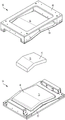
图6是图4的压缩模具设备的压缩模具部件的说明性中间部分的等距视图。6 is an isometric view of an illustrative middle portion of a compression mold component of the compression mold apparatus of FIG. 4 .
图7是图6的模具部件中间部分的俯视图。FIG. 7 is a top view of the middle portion of the mold part of FIG. 6 .
图8是图6的模具部件中间部分的正视图。FIG. 8 is a front view of the middle portion of the mold part of FIG. 6 .
图9是沿着图7中指出的方向截取的图6的模具部件中间部分的剖视图。FIG. 9 is a cross-sectional view of the middle portion of the mold part of FIG. 6 taken in the direction indicated in FIG. 7 .
图10是沿着图8中指出的方向截取的图6的模具部件中间部分的剖视图。10 is a cross-sectional view of the middle portion of the mold part of FIG. 6 taken in the direction indicated in FIG. 8 .
图11是图4的压缩模具设备的说明性压缩模具部件的等距视图。11 is an isometric view of illustrative compression mold components of the compression mold apparatus of FIG. 4 .
图12是图4的压缩模具设备的另一说明性压缩模具部件的等距视图。12 is an isometric view of another illustrative compression mold component of the compression mold apparatus of FIG. 4 .
图13是描绘与图4的压缩模具设备结合使用的压力机的示意图。FIG. 13 is a schematic diagram depicting a press used in conjunction with the compression mold apparatus of FIG. 4 .
图14是描绘增材制造的说明性方法的步骤的流程图。14 is a flowchart depicting steps of an illustrative method of additive manufacturing.
图15是描绘适于执行图14的方法的说明性增材制造装置的示意图。FIG. 15 is a schematic diagram depicting an illustrative additive manufacturing apparatus suitable for performing the method of FIG. 14 .
图16是描绘根据本公开的各方面的制造匹配压缩成型模具的说明性方法的步骤的流程图。16 is a flowchart depicting the steps of an illustrative method of making a matching compression molding mold in accordance with aspects of the present disclosure.
图17是描绘根据本公开的各方面的制造压缩成型部件的说明性方法的步骤的流程图。17 is a flowchart depicting the steps of an illustrative method of making a compression molded part in accordance with aspects of the present disclosure.
具体实施方式detailed description
具有增材制造部件的匹配压缩模具设备的各个方面和示例以及相关方法在下面描述并在相关附图中图示。除非另有说明,否则根据本教导的匹配压缩模具设备和/或其各种部件可以但不要求包含所描述、说明和/或并入本文的结构、部件、功能和/或变型中的至少一个。此外,除非明确排除,否则本文结合本教导描述、说明和/或并入的过程步骤、结构、部件、功能和/或变型可以包括在其他类似的装置和方法中,这包括在所公开的实施方式之间可互换。各种示例的以下描述本质上仅是说明性的,并且决不旨在限制本公开、其应用或用途。另外,由下面描述的示例和实施方式提供的优点本质上是说明性的,并非所有示例和实施方式都提供相同的优点或相同程度的优点。Various aspects and examples of matching compression mold apparatus with additively manufactured components and related methods are described below and illustrated in the associated drawings. Unless otherwise stated, a matching compression mold apparatus according to the present teachings and/or its various components may, but is not required to, incorporate at least one of the structures, components, functions and/or variations described, illustrated and/or incorporated herein . Furthermore, unless expressly excluded, process steps, structures, components, functions and/or variations described, illustrated and/or incorporated herein in connection with the present teachings may be included in other similar apparatuses and methods, including in disclosed implementations. The methods are interchangeable. The following description of various examples is merely illustrative in nature, and is in no way intended to limit the disclosure, its application, or uses. Additionally, the advantages provided by the examples and implementations described below are illustrative in nature and not all examples and implementations provide the same advantages or advantages to the same degree.
该具体实施方式包括以下部分,各部分依次如下:(1)定义;(2)概述;(3)示例、部件和替代方案;(4)说明性组合和附加示例;(5)优点、特征和益处;以及(6)结论。示例、部件和替代方案部分进一步分为A至F小节,每个小节都相应地标记。The Detailed Description includes the following sections, in order: (1) Definitions; (2) Overview; (3) Examples, Components, and Alternatives; (4) Illustrative Combinations and Additional Examples; benefits; and (6) conclusions. The Examples, Components, and Alternatives sections are further divided into subsections A through F, each labeled accordingly.
定义definition
除非另有说明,否则以下定义适用于本文。Unless otherwise stated, the following definitions apply herein.
“基本上”意味着或多或少地符合由该术语修饰的特定尺寸、范围、形状、概念或其他方面,使得特征或部件不需要精确地符合。例如,“基本上圆柱形”的物体意味着物体类似于圆柱形,但是可以具有与真实圆柱形的一个或多个偏差。"Substantially" means more or less conforming to the particular size, extent, shape, concept or other aspect modified by the term such that the features or components need not conform exactly. For example, an object that is "substantially cylindrical" means that the object resembles a cylinder, but may have one or more deviations from a true cylinder.
“包括(comprising)”、“包括(including)”和“具有(having)”(及其变体)可互换使用以表示包括但不必限于,并且是不旨在排除另外的、未列举的元件或方法步骤的开放式术语。"comprising", "including" and "having" (and variations thereof) are used interchangeably to mean including but not necessarily limited to, and are not intended to exclude additional, non-recited elements or an open-ended term for a method step.
诸如“第一”、“第二”和“第三”的术语用于区分或识别组的各种成员等,并且不旨在显示连续或数字限制。Terms such as "first," "second," and "third" are used to distinguish or identify various members of a group, etc., and are not intended to imply sequential or numerical limitations.
概述overview
一般而言,根据本教导的匹配的压缩模具设备包括第一压缩模具部件和第二压缩模具部件。工件(也被称为填料)设置在第一模具部件和第二模具部件的相应中间部分之间。中间部分被配置成使工件成型为期望形状。匹配的压缩模具设备进一步包括压缩装置,压缩装置被配置成将中间部分朝向彼此挤压。压缩模具设备的加热机构加热中间部分,以促进工件的成型和/或固化。In general, a matched compression mold set according to the present teachings includes a first compression mold part and a second compression mold part. A workpiece (also referred to as filler) is arranged between the respective intermediate portions of the first mold part and the second mold part. The intermediate portion is configured to form the workpiece into a desired shape. The matching compression mold set further includes compression means configured to compress the intermediate portions towards each other. The heating mechanism of the compression mold apparatus heats the middle section to facilitate shaping and/or curing of the workpiece.
可以增材制造匹配的压缩模具设备的一个或多个部件。增材制造通常包括:根据数字设计信息在有序层中施加原料(例如,金属、热塑性塑料等);以及选择性地结合和/或熔合所施加的层以产生期望的物体。增材制造技术可以包括3D打印、快速原型制作、直接数字制造、分层制造、增材生产等。本公开的一个或两个压缩模具部件可以通过增材制造来生产。在一些示例中,仅压缩模具部件的中间部分通过增材制造来生产,而压缩模具部件和设备的其他部分通过诸如机加工之类的传统手段来制造。One or more components of a matching compression mold apparatus may be additively manufactured. Additive manufacturing typically involves applying raw materials (eg, metals, thermoplastics, etc.) in ordered layers based on digital design information; and selectively bonding and/or fusing the applied layers to produce the desired object. Additive manufacturing techniques can include 3D printing, rapid prototyping, direct digital manufacturing, layered manufacturing, additive production, and more. One or both compression mold parts of the present disclosure may be produced by additive manufacturing. In some examples, only the central portion of the compression mold part is produced by additive manufacturing, while the compression mold part and other parts of the device are manufactured by conventional means such as machining.
在一些示例中,压缩模具部件的增材制造的中间部分是可互换的。例如,各被配置成使工件成型为不同形状的多个中间部分可以增材制造并且选择性地安装在通用框架结构中。In some examples, the additively manufactured intermediate sections of the compression mold parts are interchangeable. For example, multiple intermediate sections, each configured to shape a workpiece into a different shape, may be additively manufactured and selectively mounted in a common frame structure.
本文描述的匹配的压缩模具设备通常用于制造飞行器内部面板。例如,如果设备将要用于将工件转变为轮廓面板,则压缩模具部件的中间部分可以各被配置成使轮廓成型在工件的侧面上。The matched compression mold apparatus described herein is commonly used to manufacture aircraft interior panels. For example, if the apparatus is to be used to convert a workpiece into a profiled panel, the intermediate portions of the compression mold parts may each be configured to profile the sides of the workpiece.
示例、部件和替代方案Examples, Parts and Alternatives
以下章节描述了示例性压缩模具设备的选定方面以及相关系统和方法。这些章节中的示例旨在用于说明,而不应被解释为限制本公开的整个范围。每个章节均可以包括一个或多个不同的实施方式或示例,和/或包括上下文或相关信息、功能和/或结构。The following sections describe selected aspects of an exemplary compression mold apparatus and related systems and methods. The examples in these sections are intended for illustration and should not be construed as limiting the entire scope of the disclosure. Each section may include one or more different implementations or examples, and/or include contextual or related information, functions, and/or structures.
A、说明性夹层板A. Illustrative sandwich panel
如图1至图2所示,该章节描述了说明性夹层板25。夹层板25是可以使用如上所述的压缩模具设备制造的飞行器内部面板的一个示例。As shown in FIGS. 1-2 , this section describes an
图1是夹层板25的等距视图。一个或多个夹层板25可用于形成飞行器的内部部分,诸如地板、天花板和/或壁。夹层板25是包括多个层的夹层复合板,并且通常具有轮廓形状。夹层板25的第一侧27和第二侧(未示出)可以具有相同的轮廓(如图1所示),或者可以具有不同的轮廓。FIG. 1 is an isometric view of a
图2描绘了夹层板25的说明性层。夹层板25包括设置在第一面层33和第二面层34之间的蜂窝芯32。面层33和34可各自包括热固性聚合物基质,诸如环氧树脂和/或酚醛树脂,并且还可以包含增强系统,诸如碳纤维、芳族聚酰胺、玻璃纤维、编织玻璃纤维布等。另外或替代地,面层33和34可包括热塑性材料和/或其他聚合物。FIG. 2 depicts illustrative layers of a
蜂窝芯32包括以蜂窝图案布置的多个中空柱36,每个柱均具有基本上六边形的横截面并且在面层33和34之间延伸。可以包括粘合性薄膜层38和39以将蜂窝芯的相应侧面粘合到面层33和34。在一些示例中,夹层板25还包括一个或多个阻燃涂层40。另外或替代地,涂层40可以包括装饰材料,诸如涂料。
夹层板25是可以使用如上所述的压缩模具设备制造的物体的一个示例。例如,可以在压碎芯成型过程中使用压缩模具设备制造夹层板25。另外或替代地,压缩模具设备可以用于制造其他类型的面板和/或其他类型的物体。
B、说明性的匹配的压缩模具设备B. Illustrative Matched Compression Mold Apparatus
如图3至图13所示,该章节描述了说明性的匹配的压缩模具设备50。匹配的压缩模具设备50是如上所述的匹配的压缩模具设备的一个示例。如图3示意性所示,匹配的压缩模具设备50包括增材制造的第一模具部件55、增材制造的第二模具部件56、压缩装置57和加热机构58。As shown in FIGS. 3-13 , this section describes an illustrative matched
图4描绘了匹配的压缩模具设备50,其包括增材制造的第一模具部件55和增材制造的第二模具部件56。增材制造的第一模具部件55包括由第一框架结构63支撑的第一中间部分61。增材制造的第二模具部件56包括由第二框架结构68支撑的第二中间部分66。在典型的使用中,增材制造的第一模具部件55设置在增材制造的第二模具部件56上方,其中第一中间部分61和第二中间部分66彼此面对。FIG. 4 depicts a matched compression mold set 50 comprising an additively manufactured
第一中间部分61和第二中间部分66被配置成协同地成形设置在第一中间部分和第二中间部分之间的工件70(参见图5)的相对两侧。例如,第一中间部分61可以被配置成将轮廓成型在工件70的第一侧(未示出)上,并且第二中间部分66可以被配置成将轮廓成型在工件70的第二侧72上。图5是压缩模具设备50的局部分解图,图示了工件70在第一中间部分61和第二中间部分66之间的位置。The first
通常,压缩模具设备50被配置成制造飞行器的内部面板,诸如固体热固性酚醛墙板、夹层热固性酚醛墙板等。因此,在一些示例中,第一中间部分61和第二中间部分66分别包括基本上平坦的和/或轮廓化的第一成形表面73和第二成形表面76(参见图11),第一成形表面73和第二成形表面76被配置成将工件70成型为板。在一些示例中,第一中间部分61的第一成形表面73的轮廓为凸形,并且第二中间部分66的第二成形表面76的轮廓为凹形。在这些示例中,第一中间部分61可以被称为芯构件,并且第二中间部分66可以被称为腔构件。在本公开的附图中,底部模具部件被描绘为包括芯构件,并且顶部模具部件被描绘为包括腔构件。然而,在一些示例中,底部模具部件包括腔构件,并且顶部模具部件包括芯构件。Typically, the
在一些示例中,第一中间部分61和第二中间部分66具有类似的曲率、几何特征和/或材料成分。这些示例可适于形成具有基本均匀厚度的飞行器面板,该飞行器面板的两侧具有匹配的偏移曲率。In some examples, first
在一些示例中,第一中间部分61和第二中间部分66被配置成可互换的,并且第一框架结构63和第二框架结构68是通用的和/或固定的结构,所述结构被配置成选择性地支撑多个不同的可互换的中间部分中的任何一个。可以提供多个不同的可互换的第一中间部分61和/或多个不同的可互换的第二中间部分66,用于成型不同形状的工件70。例如,具有特定形状的飞行器面板可以使用被配置用于成型特定面板形状的选定的第一中间部分61和选定的第二中间部分66来制造。In some examples, the first
图6至图10描绘了说明性的第一中间部分61。图6是中间部分61的等距视图,描绘了凸的成形表面73。图7和图8分别是中间部分61的俯视图和正视图。图9是沿图7中所示方向的剖视图,而图10是沿图8中所示方向的剖视图。6-10 depict an illustrative first
图11和图12是描绘增材制造的第一模具部件55和增材制造的第二模具部件56的分解图,其包括分别安装到第一框架结构63和第二框架结构68的第一中间部分61和第二中间部分66。在图11和图12描绘的示例中,第一中间部分61和第二中间部分66分别使用螺栓和销的组件附接到第一框架结构63和第二框架结构68。另外或替代地,第一中间部分61和第二中间部分66可以使用闩锁、夹子、夹具、螺钉、钉子和/或任何其他合适的紧固件附接到第一框架结构63和第二框架结构68。在一些示例中,第一框架结构63和第二框架结构68包括凹槽、缝隙和/或配置成接收第一中间部分61和第二中间部分66的部分的其他合适的开口,并且通过定位中间部分以使得这些部分被接收在相应的开口内,中间部分安装在相应的框架结构内。FIGS. 11 and 12 are exploded views depicting an additively manufactured
如上所述,第一中间部分61和第二中间部分66可以被配置成可互换的,并且第一框架结构63和第二框架结构68可以是固定的。因此,用于将第一中间部分61和第二中间部分66安装到第一框架结构63和第二框架结构68的机构可以被配置成使得中间部分可以容易地安装到相应的框架结构并且从相应的框架结构移除而不会损坏中间部分或框架结构。图11至图12中描绘的螺栓和销组件是安装机构的示例,其能够将可互换的第一中间部分61和第二中间部分66安装到第一框架结构63和第二框架结构68并且从第一框架结构63和第二框架结构68移除。As noted above, the first
如上所述,第一中间部分61和第二中间部分66通常至少部分地通过增材制造来制造。例如,第一中间部分61和第二中间部分66可以例如由金属和/或热塑性材料来增材制造。增材制造第一中间部分61和第二中间部分66所需的相对较小的成本和制造时间可以有助于生产不同的第一中间部分和第二中间部分,这些第一中间部分和第二中间部分被配置用于制造例如不同的飞行器面板结构。第一框架结构63和第二框架结构68可以全部或部分地增材制造和/或可以通过其他手段(例如,机械加工)制造。第一框架结构63和第二框架结构68通常是刚性结构。As mentioned above, the first
第一框架结构63和第二框架结构68可以包括对准特征,该对准特征被配置成当框架结构被压在一起以使工件70成型时便于框架结构的正确对准。如图11至图12所描绘的,第一框架结构63可以包括从第一框架结构突出的一个或多个对准突起79,并且第二框架结构68可以包括配置成接收对准突起的相应的对准凹口82。可选地,一个或多个对准块85(例如,垫块和/或间隔块)可设置在对准突起79上和/或对准凹口82内,以调节第一框架结构63和第二框架结构68之间的对准和/或竖直间距。The
如图11至图12所示,第一加热毯87附接到第一中间部分61,并且第二加热毯90附接到第二中间部分66。第一加热毯87和第二加热毯90是用于匹配的压缩模具设备50的加热机构58的示例,如上所述。通常,第一加热毯87连接到第一中间部分61的与第一成形表面73相对的第一非成形表面93(参见图8至图10),并且第二加热毯90连接到第二中间部分66的与第二成形表面76相对的第二非成形表面96(参见图5)。第一加热毯87和第二加热毯90被配置成向第一模具部件55和第二模具部件56提供热量,这可以促进工件70的成型(例如,工件中的热塑性材料和/或其他聚合物材料的成型。另外或替代地,由第一加热毯87和第二加热毯90提供的热量可以促进工件内的任何热固性材料的固化。可根据需要提供电连接、处理逻辑、热电偶和/或其他合适的温度传感器、冷却机构和用于控制由第一加热毯87和第二加热毯90提供的热量的任何其他合适的设备。As shown in FIGS. 11-12 , a
在一些示例中,第一加热毯87和第二加热毯90包括“智能感受器”,其被配置成基于实际温度和感受器的居里温度之间的差异使用由感应加热产生的热量的自动变化来将温度保持在预定范围内。另外或替代地,第一加热毯87和第二加热毯90可以配置成通过电阻加热产生热量。在一些示例中,第一加热毯87和第二加热毯90包括碳纳米管薄膜,其被配置成通过例如电阻加热来产生热量。In some examples,
在一些示例中,第一加热毯87和第二加热毯90包括分别在第一非成形表面93和第二非成形表面96上彼此相邻设置的多个加热毯。在这些示例中,第一加热毯87和第二加热毯90可称为多区加热毯和/或多区加热毯系统。每个组成加热毯或组成加热毯的子集可包括相应的电源和配置成控制热量产生的处理逻辑。使用多个加热毯可以改善热均匀性和/或可以安装和/或更换加热毯的容易性。In some examples,
第一加热毯87和第二加热毯90可以通过粘合剂粘合到第一中间部分61和第二中间部分66(例如,粘合到第一非成形表面93和第二非成形表面96)。粘合剂可包括树脂,诸如酚醛树脂、环氧树脂等。在一些示例中,将具有高导热率的材料结合到粘合剂树脂中,以提高从第一加热毯87和第二加热毯90到第一中间部分61和第二中间部分66的热传递效率。The
如图4至图5和图11至图12所描绘的,第一框架结构63和第二框架结构68可以基本上邻近第一非成形表面93和第二非成形表面96敞口,以便于接近第一加热毯87和第二加热毯90,例如,用于安装和/或保养加热毯。当不期望接近第一加热毯87和第二加热毯90时,可以提供可移除的盖子以覆盖第一框架结构63和第二框架结构68上的开口;盖子可以防止损坏和/或热量损失。As depicted in FIGS. 4-5 and 11-12 , the
在一些示例中,省略了第一加热毯87和第二加热毯90,并且压缩模具设备50设置在烘炉内。在一些示例中,烘炉可以配置成通过替代的加热源加热压缩模具设备50。In some examples,
第一加热毯87和第二加热毯90和/或任何其他加热机构58可以配置成将工件70加热到150和350华氏度之间的温度,和/或200到300华氏度之间的温度。在一些示例中,加热机构58被配置成加热第一模具部件55和第二模具部件56,使得第一成形表面73和第二成形表面76中的每者上的温度在预定范围内是均匀的(例如,在±16华氏度,和/或±12华氏度,和/或±8华氏度,和/或±4华氏度的公差内,和/或任何其他合适的公差内是均匀的)。如果第一模具部件55和第二模具部件56由热塑性材料制成,则模具部件被加热达到的温度(例如,适合于热固性工件70的温度)低于热塑性塑料转变温度。热塑性材料在高于工件70的温度的温度下保持固态。
图13描绘了说明性压力机100,其被配置成施加将第一中间部分61和第二中间部分66(例如,芯构件和腔构件)朝向彼此引导的力。压力机100是上述压缩装置57的一个示例。压力机100包括第一压板103、第二压板106以及致动器110,致动器110被配置成迫使压板朝向彼此。致动器110可包括一个或多个液压缸、气动缸等。第一模具部件55和第二模具部件56定位在第一压板103和第二压板106之间,使得压板朝向彼此挤压也使第一中间部分61和第二中间部分66朝向彼此挤压。例如,第一压板103可以接合第一模具部件55的底侧,并且第二压板106可以接合第二模具部件56的顶侧。在说明性压力机100中,第一压板103固定在适当位置并且第二压板106可滑动地安装在框架115上。至少部分地由框架115支撑的致动器110被配置成将第二压板106推向第一压板103。致动器110还可以配置成将第二压板106抬离第一压板103。在一些示例中,相反,第二压板106被固定就位,而第一压板103可移动;在其他示例中,两个压板都是可移动的。FIG. 13 depicts an
压力机100可以被配置成施加至少50磅/平方英寸(PSI)的压力,迫使第一中间部分61和第二中间部分66朝向彼此。在一些示例中,压力机100可以被配置成施加50PSI至250PSI的压力,迫使第一中间部分61和第二中间部分66朝向彼此。The
如上所述,匹配的压缩模具设备50的至少一些部件是增材制造的。在一些示例中,第一模具部件55和第二模具部件56完全是增材制造的;在一些示例中,第一中间部分61和第二中间部分66是增材制造的,并且第一框架结构63和第二框架结构68通过其他方法制造。因为匹配的压缩模具设备50至少部分地增材制造,所以与通过传统方法制造的压缩模具设备相比,它可以具有相对小的重量。例如,匹配的压缩模具设备50的增材制造部分可以由轻质材料(诸如热塑性塑料)制成。另外或替代地,增材制造工艺可以允许使用比常规制造方法可行的材料更少的材料来制造匹配的压缩模具设备50的部分;因此,匹配的压缩模具设备50可以比完全由传统方法制造的设备重量更轻,即使匹配的压缩模具设备50的增材制造部分由诸如钢的常规材料制成。在一些示例中,匹配的压缩模具设备50的重量小于1000磅。在一些示例中,匹配的压缩模具设备50的重量小于500磅。相比之下,已知的匹配的压缩模具设备通常重量超过10,000磅,并且可能重量超过14,000磅,或超过20,000磅。As noted above, at least some components of the mating
C、增材制造的说明性方法C. An Illustrative Approach to Additive Manufacturing
该章节描述了用于增材制造增材制造的工件(例如,第一模具部件55和第二模具部件56和/或第一中间部分61和第二中间部分66)的说明性方法的步骤;参见图14。图15中描绘的说明性增材制造装置的各方面可用于下面描述的方法步骤中。在适当的情况下,可能提及可以用于执行每个步骤的部件和系统。这些提及仅用于说明,而不是用于限制执行该方法的任何特定步骤的可能方式。This section describes the steps of an illustrative method for additively manufacturing an additively manufactured workpiece (eg, first and
作为以相对低的成本快速生产的方法,增材制造在许多行业中迅速普及。增材制造可以用来通过逐步构建对象从3D模型创建实体对象。增材制造技术通常将原料分层施加并选择性地结合原料以产生期望的对象。各层的厚度可取决于所用的具体增材制造技术。说明性技术包括选择性激光熔化(SLM)、直接金属激光烧结(DMLS)、选择性激光烧结(SLS)、熔丝制造(FFF)、线喂料增材制造和电子束熔化(EBM)等。线喂料增材制造技术可包括线材和激光增材制造(WLAM)、电子束自由形式制造(EBF3)、线材和电弧增材制造(WAAM)等。Additive manufacturing is rapidly gaining popularity in many industries as a method of rapid production at relatively low cost. Additive manufacturing can be used to create solid objects from 3D models by gradually building objects. Additive manufacturing techniques typically apply and selectively combine materials in layers to produce desired objects. The thickness of each layer can depend on the particular additive manufacturing technique used. Illustrative techniques include selective laser melting (SLM), direct metal laser sintering (DMLS), selective laser sintering (SLS), fused filament fabrication (FFF), wire-fed additive manufacturing, and electron beam melting (EBM), among others. Wire-fed additive manufacturing technologies can include wire and laser additive manufacturing (WLAM), electron beam free-form manufacturing (EBF3), wire and arc additive manufacturing (WAAM), and others.
图14是图示在说明性方法200中执行的步骤的流程图,并且可能没有描述该方法的完整过程或所有步骤。尽管下面描述并且在图14中描绘了方法200的各个步骤,但是各步骤不一定都必须执行,并且在一些情况下可以同时执行或以与所示顺序不同的顺序执行各步骤。14 is a flowchart illustrating steps performed in
在步骤202,接收描述有序多个层的数字信息。数字信息可以由如图15所描绘的增材制造装置310的计算机控制器312接收。增材制造装置310也可以被称为打印机或制造器。计算机控制器312可包括配置成接收打印机310的数字设计信息和控制功能的任何数据处理系统。图15中所示的说明性计算机控制器包括用于控制打印机功能的处理器314和用于存储接收数据的存储器316。At
所接收的信息可以包括构成三维对象的层的多个二维图案的几何数据和/或设计细节,其中三维对象是要制造的增材制造的工件328。这些层也可以描述为横截面或切片。对多个层进行排序,使得这些层可以从第一层到最后一层进行编号或组织。The received information may include geometric data and/or design details of a plurality of two-dimensional patterns of layers that make up the three-dimensional object that is the additively manufactured
方法200的步骤204包括将原料沉积在位于打印机310的构建环境320中的构建平台318上。构建平台318可包括可由计算机控制器312沿制造轴线322移动的支撑件。构建平台318可具有垂直于制造轴线322的平坦表面。Step 204 of
原料可以是适合于增材制造的任何材料,通常是流体、粉末和/或线材,并且包括但不限于光聚合物树脂、热塑性塑料、热固性材料、纯聚合物材料和/或增强聚合物材料、石膏、陶瓷和金属。该材料可以从诸如料斗、罐、线材或粉末床之类的原料源324分配。例如,铝粉可以通过由计算机控制器312致动的刷臂从粉末床扫到构建平台318上。The feedstock can be any material suitable for additive manufacturing, typically fluids, powders and/or filaments, and includes, but is not limited to, photopolymer resins, thermoplastics, thermosets, pure polymer materials and/or reinforced polymer materials, Gypsum, ceramics and metals. The material may be dispensed from a
原料可以均匀地分布在构建平台318上,或者可以以选定的图案沉积。沉积可以在计算机控制器312的控制下完成。在一些示例中,构建平台318可以浸没在原料中,并且沉积可以通过重力或流体压力来完成。在一些示例中,连接到原料源324的打印头326可以以对应于有序多个层的第一层的图案沉积原料。The feedstock can be evenly distributed on the
在步骤206,使原料改性以产生第一层。换句话说,根据描述有序多个层的第一层的设计信息并且如计算机控制器312所指示的,引起沉积材料的物理变化,以在构建平台318上实现第一层作为物理对象。In
该材料可以被打印机310的打印头326施加作用,打印头326由计算机控制器312控制。例如,打印头326可以包括通过暴露于光来固化光聚合物或通过暴露于热而烧结金属粉末的激光器。打印头326可以由计算机控制器312引导,以遵循在接收的第一层的数字信息中定义的路径,和/或由处理器314基于接收的数字信息计算的路径。The material may be applied by a
步骤208包括重新定位构建平台318。在一些示例中,构建平台318最初可以定位在距打印头326的选定距离处。可以基于打印头326要执行的过程来确定所选择的距离。在生产层之后,构建平台318可以由计算机控制器312沿着制造轴线322远离打印头326大约等于层厚度的量而重新定位。也就是说,可以移动构建平台318,使得所产生的层的顶表面与打印头326分开选定的距离。Step 208 includes repositioning the
在一些示例中,构建平台318可以开始与打印机310的另一元件(诸如原料分配部件)对准。在生产层之后,构建平台318可以由计算机控制器312沿着制造轴线322重新定位,使得所生产的层的顶表面与打印机310的所述另一元件对准。在一些示例中,在步骤208,打印头326可以重新定位,而不是构建平台318重新定位或者除了构建平台318重新定位之外。在一些示例中,可以跳过步骤208。In some examples,
在步骤210,将原料沉积在方法200的前一步骤中产生的层上。如步骤204所描述的,原料可以是任何适当的材料并且可以以任何适当的方式沉积。在步骤212,使原料改性以产生下一层,如前面针对步骤206所述。In
可以重复步骤208至212以产生所接收的数字信息的多个层中的每个层,直到产生最后一层。然后,所产生的第一层到最后一层可以包括如所接收的数字信息中所描述的增材制造的工件328。可以从打印机中取出增材制造的工件并根据需要进行后处理。例如,可以从构建平台的构建板机加工出增材制造的工件,并且可以通过机加工和/或其他方法进一步精加工细节和/或光滑表面。
D、制造匹配的压缩成型模具的说明性方法D. Illustrative method for fabricating matching compression molding tooling
该章节描述了制造匹配的压缩成型模具的说明性方法400的步骤;参见图16。在下面描述的方法步骤中可以使用说明性的增材制造装置310和/或方法200的各方面。在适当的情况下,可能提及可以用于执行每个步骤的部件和系统。这些提及仅用于说明,而不是用于限制执行该方法的任何特定步骤的可能方式。This section describes the steps of an
图16是图示在说明性方法400中执行的步骤的流程图,并且可能没有描述该方法的完整过程或所有步骤。尽管下面描述并且在图16中描绘了方法400的各个步骤,但是各步骤不一定都必须执行,并且在一些情况下可以同时执行或以与所示顺序不同的顺序执行各步骤。16 is a flowchart illustrating steps performed in
在步骤402,方法400包括增材制造芯构件。芯构件可包括例如说明性的第一模具部件55的第一中间部分61。At
在步骤404,方法400包括增材制造腔构件。腔构件可包括例如说明性的第二模具部件56的第二中间部分66。At 404 ,
增材制造步骤402和404可以包括增材制造方法200的各方面。在一些示例中,芯构件和腔构件由金属制成。在一些示例中,芯构件和腔构件由诸如丙烯酸、尼龙、聚碳酸酯等热塑性材料制成。另外或替代地,芯构件和腔构件可以由热固性材料和/或纯聚合物材料和/或增强聚合物材料制成。可以使用任何合适的增材制造技术来执行步骤402和404。Additive manufacturing steps 402 and 404 may include aspects of
在步骤406,方法400包括将第一加热元件连接到芯构件。第一加热元件可包括第一加热毯87和/或任何其他合适的加热机构。将第一加热元件连接到芯构件的步骤可以包括将第一加热元件设置在芯构件的表面上和/或芯构件内。在一些示例中,将第一加热元件连接到芯构件的步骤包括将加热元件粘合到芯构件的表面(例如,第一非成形表面93)。At 406,
在步骤408,方法400包括将第二加热元件连接到腔构件。第二加热元件可包括第二加热毯90和/或任何其他合适的加热机构。将第二加热元件连接到腔构件的步骤可以包括将第二加热元件设置在腔构件的表面上和/或腔构件内。在一些示例中,将第二加热元件连接到腔构件的步骤包括将加热元件粘合到腔构件的表面(例如,第二非成形表面96)。At 408,
在步骤410,方法400包括将芯构件和腔构件安装在框架结构中,该框架结构被配置用于使工件(例如,工件70)成型。框架结构可包括第一框架结构63和第二框架结构68,和/或适于支撑芯构件和腔构件使得它们可通过压缩装置压在一起的任何其他结构。在一些示例中,框架结构是通用框架结构,其被配置成支撑不同的芯构件和腔构件。不同的芯构件和腔构件可以被配置用于制造不同的工件,例如不同形状的飞行器面板。在这些示例中,步骤410包括在框架结构中互换不同的芯构件和/或腔构件,以制造不同的面板结构。At 410 ,
E、制造压缩成型部件的说明性方法E. Illustrative Method of Fabricating Compression Molded Parts
该章节描述了制造压缩成型部件的说明性方法500的步骤;参见图17。说明性的增材制造装置310的各方面可用于下面描述的方法步骤中。在适当的情况下,可能提及可以用于执行每个步骤的部件和系统。这些提及仅用于说明,而不是用于限制执行该方法的任何特定步骤的可能方式。This section describes the steps of an
图17是图示在说明性方法500中执行的步骤的流程图,并且可能没有描述该方法的完整过程或所有步骤。尽管下面描述并且在图17中描绘了方法500的各个步骤,但是各步骤不一定都必须执行,并且在一些情况下可以同时执行或以与所示顺序不同的顺序执行各步骤。17 is a flowchart illustrating steps performed in
在步骤502,方法500包括确定待制造的第一压缩成型部件的第一形状。例如,第一压缩成型部件可以是飞行器内部面板(例如,夹层板25),并且第一形状可以基于飞行器设计信息来确定。At 502,
在步骤504,方法500包括制造第一芯构件(例如,凸形压缩模具中间部分,诸如第一中间部分61)和第一腔构件(例如,凹形压缩模具中间部分,诸如第二中间部分66),第一芯构件和第一腔构件被配置成将第一工件(例如,工件70)协同压缩成型为在步骤502确定的第一形状。通常,第一芯构件和/或第一腔构件通过增材制造技术制造。At
在步骤506,方法500包括将第一芯构件和第一腔构件安装到框架结构(例如,包括第一框架结构63和第二框架结构68的框架结构)中。框架结构支撑第一芯构件和第一腔构件,使得它们可用于使第一工件成型。框架结构是配置成支撑不同芯构件和腔构件的通用结构。At 506 ,
在步骤508,方法500包括使用第一芯构件和第一腔构件使第一工件成型,以产生具有确定的第一形状的第一压缩成型部件。例如,可以使用诸如压力机100的压缩装置将第一腔构件朝向第一芯构件挤压,其中第一工件在它们之间,使得第一工件成型为第一压缩成型部件。在步骤508使第一工件成型的操作通常包括使用加热机构来加热第一工件,从而促进第一工件的成型和/或固化。At 508 ,
在步骤510,方法500可选地包括丢弃第一芯构件和第一腔构件。因为第一芯构件和第一腔构件的替换件可以以相对低的成本快速地增材制造,所以在使用之后(和/或在不再使用的短时间之后)丢弃第一芯构件和第一腔构件可能更具成本效益,而不是存储它们直到再次需要。丢弃第一芯构件和第一腔构件可以包括回收第一芯构件和/或第一腔构件,使得可以重复使用制造芯构件和/或腔构件的材料。例如,第一芯构件和第一腔构件可以熔化,并且至少一部分熔化的材料可以再用作原料,用于增材制造另一个物体。在重新使用之前,可以将熔化的材料储存和/或处理(例如,转化成粉末、流体、线材和/或任何其他合适的形式)。At
在步骤512,方法500可选地包括确定待制造的第二压缩成型部件的第二形状。第二压缩成型部件可以是飞行器内部面板(例如,夹层板25),并且第二形状可以基于飞行器设计信息来确定。At
在步骤514,方法500可选地包括制造第二芯构件(例如,凸形压缩模具中间部分,诸如第一中间部分61)和第二腔构件(例如,凹形压缩模具中间部分,诸如第二中间部分66),第二芯构件被配置成将第二工件(例如,工件70)协同地压缩成型为在步骤512确定的第二形状。通常,第二芯构件和/或第二腔构件是增材制造的。第二芯构件和/或第二腔构件可以部分或全部由通过回收第一芯构件和/或第一腔构件获得的材料制成。At
在一些示例中,第二压缩成型部件的第二形状与第一压缩成型部件的第一形状相同或几乎相同。因此,第二芯构件和第二腔构件可以与第一芯构件和第一腔构件相同或几乎相同。例如,如果在步骤510丢弃第一芯构件和第一腔构件,并且稍后确定需要复制第一压缩成型部件,则可以在需要时增材制造第二芯构件和第二腔构件(例如,根据需要)以压缩成型具有与第一部分相同形状的第二部分。第二工件可包括与第一工件相同的材料和/或相同的夹层材料。In some examples, the second shape of the second compression-molded component is the same or nearly the same as the first shape of the first compression-molded component. Thus, the second core member and the second cavity member may be identical or nearly identical to the first core member and first cavity member. For example, if the first core member and first cavity member are discarded at
在步骤516,方法500可选地包括将第二芯构件和第二腔构件安装到框架结构中。因为框架结构是通用框架结构,所以它支撑不同于第一芯构件和第一腔构件的第二芯构件和第二腔构件以及与第一构件基本相同的第二芯构件和第二腔构件。At 516,
在步骤518,该方法可选地包括使用第二芯构件和第二腔构件使第二工件成型为第二压缩成型部件。步骤518通常包括使用压缩装置和加热机构来压缩成型第二部分。步骤518中使用的压缩装置和/或加热机构可以是步骤508中使用的相同压缩装置和/或加热机构。At
方法500可以是精益制造的一个示例。例如,按需制造压缩模具部件(例如,何时和/或何处需要部件)可以减少和/或消除存储大量不同模具部件的需要。因为可以以相对小的前置时间制造模具部件,所以可以根据订单制造部件(例如,可以在需要部件变得明显时制造部件,而不是预期这种需要)。因此,相对于制造模具部件的常规方法,降低了制造不需要的模具部件的风险。模具部件也可以在它们将被使用的位置处或附近制造。例如,模具部件可以在压缩装置附近制造,该压缩装置难以或不可能移动到另一位置。因此,方法500节省了将模具部件运输到它们将被使用的位置所花费的时间和能量。根据精益制造和环境可持续性的原理,从第一芯构件和第一腔构件回收材料以至少部分地形成第二芯构件和第二腔构件还减少了浪费的材料。
F、说明性组合和额外示例F. Illustrative combinations and additional examples
该章节描述了具有增材制造的部件的匹配的压缩模具设备的额外方面和特征,它们作为一系列段落而没有限制地给出,其中的一些或全部段落可以出于清楚和效率而在字母数字上指定。这些段落中的每个段落均可以与一个或多个其他段落组合,和/或以任何合适的方式与本申请中其他地方的公开内容组合。以下一些段落明确提及并进一步限制其他段落,提供但不限于一些合适组合的示例。This section describes additional aspects and features of a matched compression mold apparatus with additively manufactured components, and is presented without limitation as a series of paragraphs, some or all of which may be alphanumeric for clarity and efficiency specified above. Each of these paragraphs may be combined with one or more other paragraphs, and/or with disclosure elsewhere in this application in any suitable manner. Some of the following paragraphs explicitly refer to and further limit other paragraphs, providing but not limited to examples of some suitable combinations.
A0、一种匹配的压缩模具设备,该设备包括:增材制造的第一模具部件,该增材制造的第一模具部件具有配置成使轮廓成型在工件的第一侧上的第一中间部分;增材制造的第二模具部件,该增材制造的第二模具部件具有配置成使轮廓成型在所述工件的第二侧上的第二中间部分;加热机构,该加热机构被配置成充分地加热所述第一中间部分和所述第二中间部分以将所述工件固化成期望形状;以及压缩装置,该压缩装置被配置成施加使所述第一中间部分和第二中间部分朝向彼此引导的力。A0. A matched compression mold apparatus comprising: an additively manufactured first mold part having a first intermediate portion configured to form a contour on a first side of a workpiece The second mold part of additive manufacturing, the second mold part of this additive manufacturing has the second intermediate part that is configured to make profile molding on the second side of described workpiece; Heating mechanism, this heating mechanism is configured to fully heating the first intermediate portion and the second intermediate portion to cure the workpiece into a desired shape; and compression means configured to apply the first intermediate portion and the second intermediate portion toward each other guiding force.
A1、根据段落A0所述的设备,其中,所述第一中间部分和所述第二中间部分由聚合物材料构成。A1. The apparatus of paragraph A0, wherein the first intermediate portion and the second intermediate portion are constructed of a polymeric material.
A1a、根据段落A1所述的设备,其中,所述聚合物材料包括纯聚合物材料和/或增强聚合物材料。A1a. The apparatus of paragraph A1 , wherein the polymeric material comprises pure polymeric material and/or reinforced polymeric material.
A1b、根据段落A1所述的设备,其中,所述聚合物材料包括热塑性塑料或热固性材料、纯聚合物材料和/或增强聚合物材料。A1b. The apparatus of paragraph A1 , wherein the polymeric material comprises a thermoplastic or thermosetting material, a pure polymeric material and/or a reinforced polymeric material.
A2、根据段落A0所述的设备,其中,所述第一中间部分和所述第二中间部分由金属材料构成。A2. The apparatus of paragraph A0, wherein the first intermediate portion and the second intermediate portion are constructed of a metallic material.
A3、根据段落A0至A2中的任一段落所述的设备,其中,所述加热机构包括:第一加热毯,该第一加热毯连接到所述第一中间部分的底侧;以及第二加热毯,该第二加热毯连接到所述第二中间部分的顶侧。A3. The apparatus of any of paragraphs A0 to A2, wherein the heating mechanism comprises: a first heating blanket attached to the bottom side of the first intermediate portion; and a second heating A blanket, the second heating blanket is attached to the top side of the second intermediate portion.
A4、根据段落A0至A3中的任一段落所述的设备,其中,每个模具部件均具有刚性框架结构,所述刚性框架结构被配置成支撑可互换的中间部分以成型不同形状的工件。A4. The apparatus of any of paragraphs A0 to A3, wherein each mold part has a rigid frame structure configured to support interchangeable intermediate sections to form workpieces of different shapes.
A5、根据段落A0至A4中的任一段落所述的设备,其中,所述第一中间部分和所述第二中间部分被配置成成型飞行器内部面板。A5. The apparatus of any of paragraphs A0 to A4, wherein the first intermediate portion and the second intermediate portion are configured to form an aircraft interior panel.
A6、根据段落A0至A5中的任一段落所述的设备,其中,所述第一中间部分和所述第二中间部分被配置用于蜂窝芯热固性夹层复合板的压碎芯成型。A6. The apparatus of any of paragraphs A0 to A5, wherein the first intermediate section and the second intermediate section are configured for crush core forming of a honeycomb core thermoset sandwich composite panel.
A6a、根据段落A0至A5中的任一段落所述的设备,其中,所述第一中间部分和所述第二中间部分被配置成使热塑性塑料墙板成型。A6a. The apparatus of any of paragraphs A0 to A5, wherein the first intermediate portion and the second intermediate portion are configured to shape a thermoplastic wallboard.
A7、根据段落A0至A6中的任一段落所述的设备,其中,所述第一中间部分和所述第二中间部分以及对应的加热毯被配置成将工件加热直至200华氏度至300华氏度之间的温度。A7. The apparatus of any of paragraphs A0 to A6, wherein the first intermediate portion and the second intermediate portion and corresponding heating blankets are configured to heat the workpiece up to 200 degrees Fahrenheit to 300 degrees Fahrenheit temperature between.
A8、根据段落A0至A7中的任一段落所述的设备,其中,所述压缩装置包括压力机,所述压力机被配置成施加至少50磅/平方英寸的压力,所述压力迫使各中间部分朝向彼此。A8. The apparatus of any of paragraphs A0 to A7, wherein the compressing means comprises a press configured to apply a pressure of at least 50 psi that forces each intermediate portion towards each other.
A9、根据段落A0至A8中的任一段落所述的设备,其中,所述设备的重量小于1000磅。A9. The apparatus of any of paragraphs A0 to A8, wherein the apparatus weighs less than 1000 pounds.
A10、根据段落A0至A8中的任一段落所述的设备,其中,所述设备的重量小于500磅。A10. The apparatus of any of paragraphs A0 to A8, wherein the apparatus weighs less than 500 pounds.
B0、一种匹配的压缩模具设备,该设备包括:芯构件;腔构件,所述芯构件和所述腔构件被配置成协同地成形面板的相对两侧;第一框架结构,该第一框架结构被配置成支撑所述芯构件;第二框架结构,该第二框架结构被配置成支撑所述腔构件,其中,所述框架结构是通用的,所述芯构件和所述腔构件选择性地安装在相应的框架结构中并被配置成成型特定的面板形状。B0. A matched compression mold apparatus comprising: a core member; a cavity member configured to cooperatively shape opposite sides of a panel; a first frame structure, the first frame a structure configured to support the core member; a second frame structure configured to support the cavity member, wherein the frame structure is common and the core member and the cavity member are selectively Mounted in a corresponding frame structure and configured to form a specific panel shape.
B1、根据段落B0所述的设备,其中,所述芯构件和所述腔构件是通过增材制造制造的。B1. The apparatus of paragraph B0, wherein the core member and the cavity member are manufactured by additive manufacturing.
B2、根据段落B0至B1中的任一段落所述的设备,其中,所述芯构件和所述腔构件由金属材料制成。B2. The apparatus of any of paragraphs B0-B1, wherein the core member and the cavity member are made of a metallic material.
B3、根据段落B0至B1中的任一段落所述的设备,其中,所述芯构件和所述腔构件由聚合物材料制成。B3. The apparatus of any of paragraphs B0 to B1, wherein the core member and the lumen member are made of a polymeric material.
B3a、根据段落B3所述的设备,其中,所述聚合物材料包括纯聚合物材料和/或增强聚合物材料。B3a. The apparatus of paragraph B3, wherein the polymeric material comprises pure polymeric material and/or reinforced polymeric material.
B3b、根据段落B3所述的设备,其中,所述聚合物材料包括热塑性塑料或热固性材料、纯聚合物材料和/或增强聚合物材料。B3b. The apparatus of paragraph B3, wherein the polymeric material comprises a thermoplastic or thermosetting material, a pure polymeric material, and/or a reinforced polymeric material.
B4、根据段落B0至B3中的任一段落所述的设备,所述设备进一步包括压缩装置,所述压缩装置被配置成施加使所述芯构件和所述腔构件朝向彼此引导的力。B4. The apparatus of any of paragraphs B0 to B3, further comprising a compression device configured to apply a force that directs the core member and the lumen member toward each other.
B5、根据段落B0至B4中的任一段落所述的设备,所述设备进一步包括:第一加热毯,该第一加热毯连接到所述芯构件的底侧;以及第二加热毯,该第二加热毯连接到所述腔构件的顶侧。B5. The apparatus of any of paragraphs B0 to B4, further comprising: a first heating blanket attached to the bottom side of the core member; and a second heating blanket, the first heating blanket Two heating blankets are attached to the top side of the chamber member.
C0、一种制造匹配的压缩成型模具的方法,该方法包括以下步骤:增材制造芯构件;增材制造腔构件;将第一加热元件连接到所述芯构件;将第二加热元件连接到所述腔构件;以及将所述芯构件和腔构件安装在配置成成型工件的框架结构中。C0. A method of manufacturing a matched compression molding mold, the method comprising the steps of: additively manufacturing a core member; additively manufacturing a cavity member; attaching a first heating element to said core member; attaching a second heating element to the cavity member; and mounting the core member and the cavity member in a frame structure configured to form a workpiece.
C1、根据段落C0所述的方法,其中,所述框架结构是通用的,安装步骤包括:在所述框架结构中互换不同的芯构件和腔构件以制造不同的面板结构。C1. The method of paragraph C0, wherein the frame structure is common and the step of installing includes interchanging different core members and cavity members within the frame structure to produce different panel structures.
C2、根据段落C0至C1中的任一段落所述的方法,其中,所述芯构件和所述腔构件由金属材料制成。C2. The method of any of paragraphs C0-C1, wherein the core member and the cavity member are made of a metallic material.
C3、根据段落C0至C1中的任一段落所述的方法,其中,所述芯构件和腔构件由聚合物材料制成。C3. The method of any of paragraphs C0-C1, wherein the core member and lumen member are made of a polymeric material.
C3a、根据段落C3所述的方法,其中,所述聚合物材料包括纯聚合物材料和/或增强聚合物材料。C3a. The method of paragraph C3, wherein the polymeric material comprises pure polymeric material and/or reinforced polymeric material.
C3b、根据段落C3所述的方法,其中,所述聚合物材料包括热塑性塑料或热固性材料、纯聚合物材料和/或增强聚合物材料。C3b. The method of paragraph C3, wherein the polymeric material comprises a thermoplastic or thermosetting material, a pure polymeric material, and/or a reinforced polymeric material.
D0、一种制造压缩成型部件的方法,该方法包括以下步骤:D0. A method of manufacturing a compression molded part, the method comprising the steps of:
确定待制造的第一压缩成型部件的第一形状;determining a first shape of a first compression-formed part to be manufactured;
制造第一芯构件和第一腔构件,所述第一芯构件和所述第一腔构件被配置成将第一工件协同地压缩成型为所确定的第一形状;fabricating a first core member and a first cavity member configured to cooperatively compression mold a first workpiece into a first determined shape;
将所述第一芯构件和所述第一腔构件安装到框架结构中;以及mounting the first core member and the first cavity member into a frame structure; and
使用所述第一芯构件和所述第一腔构件来成型所述第一工件,以产生具有所述确定的第一形状的所述第一压缩成型部件。The first workpiece is molded using the first core member and the first cavity member to produce the first compression molded part having the defined first shape.
D1、根据段落D0所述的方法,其中,制造第一芯构件和第一腔构件的步骤包括:增材制造所述第一芯构件和所述第一腔构件。D1. The method of paragraph D0, wherein manufacturing a first core member and a first cavity member comprises additively manufacturing the first core member and the first cavity member.
D2、根据段落D0至D1中的任一段落所述的方法,所述方法进一步包括以下步骤:在挤压步骤之后,丢弃所述第一芯构件和所述第一腔构件。D2. The method of any of paragraphs D0-D1, further comprising the step of discarding the first core member and the first lumen member after the extruding step.
D3、根据段落D0至D2中的任一段落所述的方法,其中,所述第一压缩成型部件是飞行器内部面板。D3. The method of any of paragraphs D0 through D2, wherein the first compression-formed part is an aircraft interior panel.
D4、根据段落D0至D3中的任一段落所述的方法,所述方法进一步包括以下步骤:D4. The method of any of paragraphs D0 to D3, further comprising the steps of:
确定待制造的第二压缩成型部件的第二形状;determining a second shape of the second compression-molded part to be manufactured;
制造第二芯构件和第二腔构件,所述第二芯构件和所述第二腔构件被配置成将第二工件协同地压缩成型为所确定的第二形状;fabricating a second core member and a second cavity member configured to cooperatively compress mold a second workpiece into a second determined shape;
将所述第二芯构件和所述第二腔构件安装到所述框架结构中;以及installing the second core member and the second cavity member into the frame structure; and
使用所述第二芯构件和所述第二腔构件来成型所述第二工件,以产生具有所确定的第二形状的所述第二压缩成型部件。The second workpiece is molded using the second core member and the second cavity member to produce the second compression molded part having a second determined shape.
D5、根据段落D4所述的方法,其中,制造第二芯构件和第二腔构件的步骤包括:增材制造所述第二芯构件和所述第二腔构件。D5. The method of paragraph D4, wherein manufacturing a second core member and a second cavity member comprises additively manufacturing the second core member and the second cavity member.
D6、根据段落D4至D5中的任一段落所述的方法,其中,所述第二形状与所述第一形状相同。D6. The method of any of paragraphs D4-D5, wherein the second shape is the same as the first shape.
D7、根据段落D4至D6中的任一段落所述的方法,其中,所述第二压缩成型部件是飞行器面板。D7. The method of any of paragraphs D4-D6, wherein the second compression-molded part is an aircraft panel.
优点、特征和益处Advantages, Features and Benefits
本文所描述的匹配的压缩模具设备的不同实施方式和示例提供了优于用于压缩成型热固性飞行器面板和/或其他部件的已知解决方案的若干优点。例如,与传统的生产方法相比,本文所描述的说明性实施方式和示例允许以相对高的速度和低成本生产压缩模具工具部件,尤其是在压缩模具工具部件被配置成压缩成型具有复杂轮廓的部件的情况下如此。The various embodiments and examples of matched compression mold apparatus described herein offer several advantages over known solutions for compression molding thermoset aircraft panels and/or other components. For example, the illustrative embodiments and examples described herein allow compression mold tool parts to be produced at relatively high speed and low cost compared to conventional production methods, especially when the compression mold tool parts are configured to compression mold with complex contours This is the case for components.
另外,除了其他益处之外,本文所描述的说明性实施方式和示例允许制造具有可通过通用框架部分支撑的可互换中间部分(例如,可互换的腔构件和芯构件)的压缩模具部件。因此,本文所描述的说明性实施方式和示例允许相对快速且容易地制造配置成使不同的部件成型的压缩模具工具,并且将其存储在相对小的空间中。Additionally, among other benefits, the illustrative embodiments and examples described herein allow for the manufacture of compression mold parts having interchangeable intermediate sections (eg, interchangeable cavity members and core members) that can be supported by a common frame section . Thus, the illustrative embodiments and examples described herein allow for relatively quick and easy manufacture of compression mold tools configured to shape different components and storage in a relatively small space.
另外,除了其他益处之外,本文所描述的说明性实施方式和示例允许压缩模具部件或其部分被视为一次性的。因为增材制造的模具部件和/或模具部件的中间部分制造起来相对快速且廉价,所以在某些情况下可按需制造部件(和/或部件中间部分)并在使用后将其丢弃而不是存储它们。Additionally, among other benefits, the illustrative embodiments and examples described herein allow for a compression mold part or portion thereof to be considered disposable. Because additively manufactured mold parts and/or mid-sections of mold parts are relatively quick and inexpensive to manufacture, in some cases parts (and/or part mid-sections) can be manufactured on-demand and discarded after use rather than store them.
另外,除了其他益处之外,本文所描述的说明性实施方式和示例允许压缩模具部件成本有效地制造,即使在预期部件用于压缩成型少量部件的情况下也是如此。例如,可以制造压缩模具部件,其被配置成压缩成型少量用于不再生产的飞行器模型的替换面板。相反,常规的压缩模具部件制造起来非常昂贵且耗时,因此制造仅用于成型少量部件的部件通常是不可行的。Additionally, among other benefits, the illustrative embodiments and examples described herein allow for cost-effective manufacture of compression molded parts, even where the part is intended to be used for compression molding a small number of parts. For example, a compression mold part configured to compression mold a small number of replacement panels for an aircraft model that is no longer in production may be manufactured. In contrast, conventional compression mold parts are very expensive and time-consuming to manufacture, so it is often not feasible to manufacture parts that are only used to mold a small number of parts.
另外,除了其他益处之外,本文所描述的说明性实施方式和示例允许制造压缩模具工具部件,同时浪费的材料少于通常在减成制造技术中浪费的材料。Additionally, among other benefits, the illustrative embodiments and examples described herein allow for the fabrication of compression mold tool components while wasting less material than is typically wasted in subtractive manufacturing techniques.
另外,除了其他益处之外,本文所描述的说明性实施方式和示例允许制造比传统部件重量显著更低的压缩模具工具部件。因此,本公开的压缩模具工具部件可以围绕制造环境移动,以在制造压缩成型部件时增加灵活性。例如,压缩模具部件的可互换的中间部分可以容易地从存储空间移动到压缩装置,然后返回到存储空间中。存储空间可以是远离压缩装置的远程存储空间。本文所描述的压缩模具工具部件还可以与比传统工具部件所需的功率更小的压缩装置一起使用,尤其是在压缩装置被配置成提升一个或多个工具部件的情况下。Additionally, among other benefits, the illustrative embodiments and examples described herein allow for the manufacture of compression mold tool components that weigh significantly less than conventional components. Accordingly, the compression mold tool parts of the present disclosure can be moved around the manufacturing environment for increased flexibility in manufacturing compression molded parts. For example, interchangeable intermediate sections of compression mold parts can be easily moved from the storage space to the compression device and back into the storage space. The storage space may be a remote storage space away from the compression device. The compression mold tool components described herein may also be used with compression devices that require less power than conventional tool components, especially where the compression devices are configured to lift one or more tool components.
没有已知的系统或装置可以执行这些功能。然而,并非本文所描述的所有实施方式和示例都提供相同的优点或相同程度的优点。There is no known system or device that can perform these functions. However, not all implementations and examples described herein provide the same advantages or the same degree of advantages.
结论in conclusion
以上阐述的公开内容可以包含具有独立效用的多个不同示例。尽管已经以其优选形式公开了这些示例中的每个示例,但是本文公开和说明的其具体实施方式不应被视为具有限制意义,因为许多变化是可能的。就本公开内容中使用的章节标题而言,这些标题仅用于组织目的。本公开的主题包括本文公开的各种元件、特征、功能和/或性质的所有新颖和非显而易见的组合和子组合。随附权利要求特别指出了被视为新颖和非显而易见的某些组合和子组合。特征、功能、元件和/或性质的其他组合和子组合可以在要求来自本申请或相关申请的优先权的申请中要求保护。这些权利要求无论是否与原始权利要求的范围相比更宽、更窄、相同或不同,也被认为包括在本公开的主题内。The disclosure set forth above may contain a number of different examples with independent utility. While each of these examples has been disclosed in its preferred form, the specific implementations thereof disclosed and illustrated herein should not be considered limiting, as many variations are possible. To the extent that section headings are used in this disclosure, these headings are used for organizational purposes only. The subject matter of the present disclosure includes all novel and nonobvious combinations and subcombinations of the various elements, features, functions and/or properties disclosed herein. The following claims particularly point out certain combinations and subcombinations which are regarded as novel and non-obvious. Other combinations and subcombinations of features, functions, elements, and/or properties may be claimed in applications claiming priority from this or a related application. Such claims, whether broader, narrower, equal, or different in scope to the original claims, also are regarded as included within the subject matter of the present disclosure.
Claims (10)
Priority Applications (1)
| Application Number | Priority Date | Filing Date | Title |
|---|---|---|---|
| CN202211484138.4A CN115782019B (en) | 2018-05-30 | 2019-05-30 | Matching compression mold equipment and manufacturing method thereof |
Applications Claiming Priority (2)
| Application Number | Priority Date | Filing Date | Title |
|---|---|---|---|
| US15/992,465 US11351703B2 (en) | 2018-05-30 | 2018-05-30 | Matched compression die apparatus |
| US15/992,465 | 2018-05-30 |
Related Child Applications (1)
| Application Number | Title | Priority Date | Filing Date |
|---|---|---|---|
| CN202211484138.4A Division CN115782019B (en) | 2018-05-30 | 2019-05-30 | Matching compression mold equipment and manufacturing method thereof |
Publications (2)
| Publication Number | Publication Date |
|---|---|
| CN110549532A CN110549532A (en) | 2019-12-10 |
| CN110549532B true CN110549532B (en) | 2022-12-16 |
Family
ID=68655196
Family Applications (2)
| Application Number | Title | Priority Date | Filing Date |
|---|---|---|---|
| CN202211484138.4A Active CN115782019B (en) | 2018-05-30 | 2019-05-30 | Matching compression mold equipment and manufacturing method thereof |
| CN201910460718.1A Active CN110549532B (en) | 2018-05-30 | 2019-05-30 | Matching compression mold apparatus and manufacturing method thereof |
Family Applications Before (1)
| Application Number | Title | Priority Date | Filing Date |
|---|---|---|---|
| CN202211484138.4A Active CN115782019B (en) | 2018-05-30 | 2019-05-30 | Matching compression mold equipment and manufacturing method thereof |
Country Status (4)
| Country | Link |
|---|---|
| US (1) | US11351703B2 (en) |
| JP (1) | JP7312609B2 (en) |
| CN (2) | CN115782019B (en) |
| CA (1) | CA3044213C (en) |
Families Citing this family (2)
| Publication number | Priority date | Publication date | Assignee | Title |
|---|---|---|---|---|
| WO2020257693A1 (en) * | 2019-06-19 | 2020-12-24 | Arris Composites Inc. | Multi-part molds and methods for forming complex fiber-composite parts |
| US20260001258A1 (en) * | 2024-06-27 | 2026-01-01 | The Boeing Company | System and method for forming a panel for an internal cabin of a vehicle |
Citations (1)
| Publication number | Priority date | Publication date | Assignee | Title |
|---|---|---|---|---|
| US5648137A (en) * | 1994-08-08 | 1997-07-15 | Blackmore; Richard | Advanced cured resin composite parts and method of forming such parts |
Family Cites Families (16)
| Publication number | Priority date | Publication date | Assignee | Title |
|---|---|---|---|---|
| US4250397A (en) * | 1977-06-01 | 1981-02-10 | International Paper Company | Heating element and methods of manufacturing therefor |
| US4560428A (en) * | 1984-08-20 | 1985-12-24 | Rockwell International Corporation | System and method for producing cured composites |
| US7963815B2 (en) * | 2000-01-14 | 2011-06-21 | Mead Kirby J | Shape-adjustable mold, skin and interior-core structures for custom board production |
| US6749794B2 (en) * | 2001-08-13 | 2004-06-15 | R + S Technik Gmbh | Method and apparatus for molding components with molded-in surface texture |
| US6510720B1 (en) * | 2001-10-18 | 2003-01-28 | Hartwick Professionals, Inc. | Hydraulic pressure forming using a self aligning and activating die system |
| JP2004074271A (en) * | 2002-06-20 | 2004-03-11 | Sumitomo Heavy Ind Ltd | Press equipment |
| CN102264520B (en) * | 2008-10-23 | 2014-04-02 | Lrm工业国际公司 | Method of forming a molded article by wireless control |
| CN101402235B (en) * | 2008-11-19 | 2010-09-15 | 上海工程技术大学 | A uniform temperature hot pressing mold device and preparation method for forming thermosetting plastic flat plate |
| JP6020826B2 (en) * | 2013-07-12 | 2016-11-02 | パナソニックIpマネジメント株式会社 | Fiber-reinforced composite material molding method and fiber-reinforced composite material molding apparatus |
| US10368401B2 (en) * | 2014-06-03 | 2019-07-30 | Aurora Flight Sciences Corporation | Multi-functional composite structures |
| US9844902B2 (en) * | 2014-10-16 | 2017-12-19 | Zimmer, Inc. | Modular mold system |
| EP3109033A1 (en) * | 2015-06-25 | 2016-12-28 | Airbus Operations GmbH | Compression mould, compression moulding tool and compression moulding method |
| CN105499562A (en) * | 2015-12-17 | 2016-04-20 | 东莞裕元模具有限公司 | Method for rapidly manufacturing mold through 3D printing materials |
| WO2018034949A1 (en) * | 2016-08-19 | 2018-02-22 | 3M Innovative Properties Company | Sound-absorbing panels comprising a core consisting of connected cells, wherein some of the cell walls have openings |
| US9902108B1 (en) * | 2017-08-31 | 2018-02-27 | Capital One Services, Llc | Rapid prototyping method of producing tooling for an injection mold |
| CN107756691B (en) * | 2017-11-06 | 2024-04-19 | 深圳市迪嘉机械有限公司 | Novel rapid plastic mold and manufacturing method thereof |
-
2018
- 2018-05-30 US US15/992,465 patent/US11351703B2/en active Active
-
2019
- 2019-05-23 CA CA3044213A patent/CA3044213C/en active Active
- 2019-05-29 JP JP2019100194A patent/JP7312609B2/en active Active
- 2019-05-30 CN CN202211484138.4A patent/CN115782019B/en active Active
- 2019-05-30 CN CN201910460718.1A patent/CN110549532B/en active Active
Patent Citations (1)
| Publication number | Priority date | Publication date | Assignee | Title |
|---|---|---|---|---|
| US5648137A (en) * | 1994-08-08 | 1997-07-15 | Blackmore; Richard | Advanced cured resin composite parts and method of forming such parts |
Also Published As
| Publication number | Publication date |
|---|---|
| US11351703B2 (en) | 2022-06-07 |
| JP2020019273A (en) | 2020-02-06 |
| CN110549532A (en) | 2019-12-10 |
| CA3044213C (en) | 2023-08-15 |
| CA3044213A1 (en) | 2019-11-30 |
| US20190366599A1 (en) | 2019-12-05 |
| JP7312609B2 (en) | 2023-07-21 |
| BR102019011048A2 (en) | 2019-12-03 |
| CN115782019A (en) | 2023-03-14 |
| CN115782019B (en) | 2025-10-28 |
Similar Documents
| Publication | Publication Date | Title |
|---|---|---|
| US9409349B2 (en) | Formed sheet metal composite tooling | |
| US11247367B2 (en) | 3D-printed tooling shells | |
| US11155005B2 (en) | 3D-printed tooling and methods for producing same | |
| US8383998B1 (en) | Tooling inserts for laminated tooling | |
| US20160375609A1 (en) | Compression mold, compression molding tool and compression molding method | |
| US11400620B2 (en) | Methods and apparatus for curing composite nacelle structure | |
| CN104690980B (en) | Thermoplastic composite support structure with integral fittings and method of manufacture | |
| JP2014510652A (en) | Manufacturing method of composite material product, manufacturing apparatus thereof, and product manufactured by this method or apparatus | |
| CN110549532B (en) | Matching compression mold apparatus and manufacturing method thereof | |
| US10093067B2 (en) | Method of forming a carbon fiber layup | |
| US11331867B2 (en) | Nested manufacturing of composite structures | |
| US7858012B2 (en) | Automated prototyping of a composite airframe | |
| CN111745877A (en) | System and method for making composite parts | |
| US10493689B1 (en) | Methods for forming thermoplastic parts with freeform tooling | |
| BR102019011048B1 (en) | COMBINED COMPRESSION DIE APPARATUS, AND, METHOD FOR MANUFACTURING A COMBINED COMPRESSION MOLD DIE | |
| WO2022018456A1 (en) | Mould for a composite component | |
| JP5729060B2 (en) | Method and apparatus for molding fiber reinforced plastic | |
| JP7606714B1 (en) | Manufacturing apparatus and manufacturing method for fiber reinforced plastic molded products | |
| Cloud et al. | Low‐cost tooling for composite parts:“the LCTC process” | |
| Cameron | RapidClave® Technology Demonstrations–II Hat Stiffener |
Legal Events
| Date | Code | Title | Description |
|---|---|---|---|
| PB01 | Publication | ||
| PB01 | Publication | ||
| SE01 | Entry into force of request for substantive examination | ||
| SE01 | Entry into force of request for substantive examination | ||
| GR01 | Patent grant | ||
| GR01 | Patent grant |