CN110488838B - An accurate and repeatable positioning method for indoor autonomous navigation robot - Google Patents
An accurate and repeatable positioning method for indoor autonomous navigation robot Download PDFInfo
- Publication number
- CN110488838B CN110488838B CN201910805799.4A CN201910805799A CN110488838B CN 110488838 B CN110488838 B CN 110488838B CN 201910805799 A CN201910805799 A CN 201910805799A CN 110488838 B CN110488838 B CN 110488838B
- Authority
- CN
- China
- Prior art keywords
- robot
- current
- target position
- positioning
- coordinate
- Prior art date
- Legal status (The legal status is an assumption and is not a legal conclusion. Google has not performed a legal analysis and makes no representation as to the accuracy of the status listed.)
- Expired - Fee Related
Links
Images


Classifications
-
- G—PHYSICS
- G05—CONTROLLING; REGULATING
- G05D—SYSTEMS FOR CONTROLLING OR REGULATING NON-ELECTRIC VARIABLES
- G05D1/00—Control of position, course, altitude or attitude of land, water, air or space vehicles, e.g. using automatic pilots
- G05D1/02—Control of position or course in two dimensions
- G05D1/021—Control of position or course in two dimensions specially adapted to land vehicles
- G05D1/0212—Control of position or course in two dimensions specially adapted to land vehicles with means for defining a desired trajectory
- G05D1/0221—Control of position or course in two dimensions specially adapted to land vehicles with means for defining a desired trajectory involving a learning process
-
- G—PHYSICS
- G05—CONTROLLING; REGULATING
- G05D—SYSTEMS FOR CONTROLLING OR REGULATING NON-ELECTRIC VARIABLES
- G05D1/00—Control of position, course, altitude or attitude of land, water, air or space vehicles, e.g. using automatic pilots
- G05D1/02—Control of position or course in two dimensions
- G05D1/021—Control of position or course in two dimensions specially adapted to land vehicles
- G05D1/0212—Control of position or course in two dimensions specially adapted to land vehicles with means for defining a desired trajectory
- G05D1/0223—Control of position or course in two dimensions specially adapted to land vehicles with means for defining a desired trajectory involving speed control of the vehicle
-
- G—PHYSICS
- G05—CONTROLLING; REGULATING
- G05D—SYSTEMS FOR CONTROLLING OR REGULATING NON-ELECTRIC VARIABLES
- G05D1/00—Control of position, course, altitude or attitude of land, water, air or space vehicles, e.g. using automatic pilots
- G05D1/02—Control of position or course in two dimensions
- G05D1/021—Control of position or course in two dimensions specially adapted to land vehicles
- G05D1/0231—Control of position or course in two dimensions specially adapted to land vehicles using optical position detecting means
- G05D1/0234—Control of position or course in two dimensions specially adapted to land vehicles using optical position detecting means using optical markers or beacons
- G05D1/0236—Control of position or course in two dimensions specially adapted to land vehicles using optical position detecting means using optical markers or beacons in combination with a laser
-
- G—PHYSICS
- G05—CONTROLLING; REGULATING
- G05D—SYSTEMS FOR CONTROLLING OR REGULATING NON-ELECTRIC VARIABLES
- G05D1/00—Control of position, course, altitude or attitude of land, water, air or space vehicles, e.g. using automatic pilots
- G05D1/02—Control of position or course in two dimensions
- G05D1/021—Control of position or course in two dimensions specially adapted to land vehicles
- G05D1/0231—Control of position or course in two dimensions specially adapted to land vehicles using optical position detecting means
- G05D1/0246—Control of position or course in two dimensions specially adapted to land vehicles using optical position detecting means using a video camera in combination with image processing means
- G05D1/0253—Control of position or course in two dimensions specially adapted to land vehicles using optical position detecting means using a video camera in combination with image processing means extracting relative motion information from a plurality of images taken successively, e.g. visual odometry, optical flow
-
- G—PHYSICS
- G05—CONTROLLING; REGULATING
- G05D—SYSTEMS FOR CONTROLLING OR REGULATING NON-ELECTRIC VARIABLES
- G05D1/00—Control of position, course, altitude or attitude of land, water, air or space vehicles, e.g. using automatic pilots
- G05D1/02—Control of position or course in two dimensions
- G05D1/021—Control of position or course in two dimensions specially adapted to land vehicles
- G05D1/0276—Control of position or course in two dimensions specially adapted to land vehicles using signals provided by a source external to the vehicle
Landscapes
- Engineering & Computer Science (AREA)
- Physics & Mathematics (AREA)
- Automation & Control Theory (AREA)
- Remote Sensing (AREA)
- Radar, Positioning & Navigation (AREA)
- General Physics & Mathematics (AREA)
- Aviation & Aerospace Engineering (AREA)
- Electromagnetism (AREA)
- Optics & Photonics (AREA)
- Computer Vision & Pattern Recognition (AREA)
- Multimedia (AREA)
- Control Of Position, Course, Altitude, Or Attitude Of Moving Bodies (AREA)
- Manipulator (AREA)
Abstract
Description
技术领域technical field
本发明涉及智能机器人领域,特别涉及一种室内自主导航机器人精确重复定位方法。The invention relates to the field of intelligent robots, in particular to an accurate and repeated positioning method for an indoor autonomous navigation robot.
背景技术Background technique
目前室内自主导航机器人大多采用码盘,陀螺仪,IMU,激光雷达等传感器采集相应信息通过融合算法来估算机器人实时的位置姿态。At present, most indoor autonomous navigation robots use encoders, gyroscopes, IMUs, lidars and other sensors to collect corresponding information and use fusion algorithms to estimate the real-time position and attitude of the robot.
码盘类似于汽车的里程计,通过计算轮毂转动的圈数来推算机器人运动的路程,但是机器人在运动过程中难免受到打滑,轮胎磨损等因素的影响导致码盘检测误差,并且会随着机器人运动逐渐累加,无法有效消除误差积累。The code disc is similar to the odometer of the car. It calculates the distance of the robot by calculating the number of turns of the wheel hub. However, the robot is inevitably affected by slippage, tire wear and other factors during the movement, which leads to the detection error of the code disc, and will follow the robot. The movement is gradually accumulated, and the accumulation of errors cannot be effectively eliminated.
陀螺仪和IMU(Inertial measurement unit惯性测量单元)由于电子器件的电气特性会出现零漂(零漂是输入为0的时候的输出)的现象,并且会随着时间误差逐渐累积,同样无法有效消除误差积累。The gyroscope and IMU (Inertial measurement unit) will have zero drift (zero drift is the output when the input is 0) due to the electrical characteristics of the electronic device, and the error will gradually accumulate with time, which cannot be effectively eliminated. Error accumulation.
激光雷达是通过激光扫描周围环境信息,经过处理得到点云信息之后通过粒子滤波算法与先验地图进行匹配最后估计出置信度最高的机器人姿态,雷达有很强的适应性,不受光照的影响,基于激光雷达的定位算法在周围定位特征较为丰富的情况下有较优秀的定位效果,但是在长直走廊周围环境较为相似的场景下会定位算法很容易失效,从而出现较大的定位偏差。Lidar scans the surrounding environment information by laser, and then obtains the point cloud information after processing, and then matches the prior map with the particle filter algorithm, and finally estimates the robot pose with the highest confidence. The radar has strong adaptability and is not affected by light. , the positioning algorithm based on lidar has better positioning effect when the surrounding positioning features are rich, but the positioning algorithm is easy to fail in the scene where the surrounding environment of the long straight corridor is relatively similar, resulting in a large positioning deviation.
上述的定位方案在长直走廊场景下,如果对机器人有长时间运行并且能精确重复定位需求的情况下,效果非常不理想,无法重复精确定位,相邻的两次定位误差甚至会大于30cm。The above positioning scheme is very unsatisfactory in the scenario of long straight corridors, if the robot needs to run for a long time and can accurately repeat the positioning requirements, the effect is very unsatisfactory, and the accurate positioning cannot be repeated, and the two adjacent positioning errors may even be greater than 30cm.
发明内容SUMMARY OF THE INVENTION
本发明的目的在于克服现有技术中所存在的上述不足,提供了一种在长直走廊场景下,减少累积误差,明显提高机器人重复精确定位的在线矫正误差的方法。The purpose of the present invention is to overcome the above-mentioned deficiencies in the prior art, and to provide a method for reducing the accumulated error and significantly improving the online correction error of the robot for repeated and precise positioning in the scenario of a long straight corridor.
为了实现上述发明目的,本发明提供了以下技术方案:In order to achieve the above-mentioned purpose of the invention, the present invention provides the following technical solutions:
一种室内自主导航机器人精确重复定位方法,步骤包括:A method for accurate and repeated positioning of an indoor autonomous navigation robot, the steps comprising:
S1,在直线上依次预设多个目标位置,机器人依次经过目标位置;S1, preset multiple target positions in sequence on a straight line, and the robot passes through the target positions in sequence;
S2,当机器人到达其中一个目标位置时,获取机器人的当前坐标;S2, when the robot reaches one of the target positions, obtain the current coordinates of the robot;
S3,计算当前目标位置的修正坐标;S3, calculate the corrected coordinates of the current target position;
S4,机器人到达目标位置的修正坐标后,采用视觉补偿定位算法,计算出机器人当前的视觉位置;S4, after the robot reaches the corrected coordinates of the target position, a visual compensation positioning algorithm is used to calculate the current visual position of the robot;
S5,根据当前坐标、当前目标位置的修正坐标和当前的精确位置,计算当前目标位置的评价系数,当前目标位置的评价系数用于计算机器人下一次经过当前目标位置的修正坐标。S5, calculate the evaluation coefficient of the current target position according to the current coordinates, the corrected coordinates of the current target position and the current precise position, and the evaluation coefficient of the current target position is used to calculate the corrected coordinates of the robot passing the current target position next time.
进一步的,步骤S3中当前目标位置的修正坐标,采用迭代的方式计算得到,计算公式为:Further, in step S3, the corrected coordinates of the current target position are calculated in an iterative manner, and the calculation formula is:
position_expi,j position_exp i,j
=factori-1,j(position_expi,j-1-position_currenti,j)+position_currenti,j =factor i-1, j (position_exp i, j - 1 -position_current i, j )+position_current i, j
其中,i表示导航点的编号,j表示机器人的寻址轮数,position_expi,j是机器人在第j轮中第i个导航点的修正坐标,factori-1,j机器人第j轮到达第i-1个导航点计算出的评价系数,position_expi,j-1是第i个导航点在第j-1轮的修正坐标,position_currenti,j是机器人在第j轮到达第i个导航点实测的当前坐标。Among them, i represents the number of the navigation point, j represents the number of addressing rounds of the robot, position_exp i, j is the corrected coordinate of the i-th navigation point of the robot in the j-th round, factor i-1, j robot reaches the j-th round of the j-th round The evaluation coefficient calculated by the i-1 navigation point, position_exp i, j-1 is the corrected coordinate of the i-th navigation point in the j-1th round, position_current i, j is the robot reaching the i-th navigation point in the jth round The measured current coordinates.
进一步的,步骤S4的具体步骤包括:Further, the specific steps of step S4 include:
S41,机器人移动到目标位置的修正坐标;S41, the corrected coordinates of the robot moving to the target position;
S42,机器人通过自身搭载的可见光相机对识别标识进行拍照,识别标识位于目标位置附近,根据识别标识的实际尺寸和照片里识别标识的像素尺寸和相机的像素焦距,计算出机器人与识别标识之间的相对姿态关系,从而计算出机器人当前的视觉位置。S42, the robot takes a picture of the identification mark through its own visible light camera, the identification mark is located near the target position, and the distance between the robot and the identification mark is calculated according to the actual size of the identification mark, the pixel size of the identification mark in the photo, and the pixel focal length of the camera. The relative pose relationship of the robot can be calculated to calculate the current visual position of the robot.
作为一种具体的实施例,识别标识为二维码图形。As a specific embodiment, the identification mark is a two-dimensional code graphic.
进一步的,当识别标识为二维码图形时,步骤S42的具体流程为:Further, when the identification mark is a two-dimensional code graphic, the specific process of step S42 is:
S401,相机内部参数的标定;S401, calibration of camera internal parameters;
S402,采用相机对二维码图形进行拍照,在拍摄的图像中识别并定位二维码图形;S402, using a camera to take pictures of the two-dimensional code graphics, and identifying and locating the two-dimensional code graphics in the captured images;
S403,通过相机内部参数进行相机坐标系与世界坐标系之间的转换;S403, the conversion between the camera coordinate system and the world coordinate system is performed through the internal parameters of the camera;
S404,根据二维码图形在图像中的位置信息,利用小孔成像原理,计算出机器人与识别标识之间的相对姿态关系。S404, according to the position information of the two-dimensional code graphic in the image, using the principle of pinhole imaging, calculate the relative attitude relationship between the robot and the identification mark.
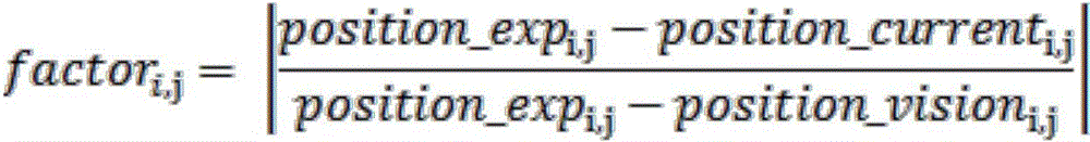
进一步的,步骤S5中评价系数计算公式为:Further, the calculation formula of the evaluation coefficient in step S5 is:
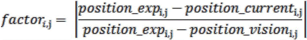
其中,factori,j是机器人在第j轮中,第i个目标位置的评价系数,position_expi,j为机器人在第j轮中第i个导航点的修正坐标,position_currenti,j为机器人在第j轮到达第i个导航点实测的当前坐标,position_visioni,j是通过视觉补偿定位算法计算到的机器人当前的视觉位置。Among them, factor i, j is the evaluation coefficient of the i-th target position of the robot in the j-th round, position_exp i, j is the corrected coordinates of the i-th navigation point of the robot in the j-th round, and position_current i, j is the robot's position in the j-th round. The jth round reaches the measured current coordinates of the i-th navigation point, position_vision i, j is the current visual position of the robot calculated by the visual compensation positioning algorithm.
本发明还保护一种室内自主导航机器人精确重复定位的系统,包括至少一个处理器,以及与至少一个处理器通信连接的存储器;存储器存储有可被至少一个处理器执行的指令,指令被至少一个处理器执行,以使至少一个处理器能够执行上述技术方案中任一项的方法。The present invention also protects a system for accurate and repeated positioning of an indoor autonomous navigation robot, comprising at least one processor and a memory connected in communication with the at least one processor; the memory stores instructions that can be executed by the at least one processor, and the instructions are executed by the at least one processor. The processor executes, so that at least one processor can execute the method of any one of the above technical solutions.
与现有技术相比,本发明的有益效果:Compared with the prior art, the beneficial effects of the present invention:
在长直走廊场景下,随着机器人的运动,实时矫正定位误差,实现机器人的精确定位,经过测试,机器人在每个点的重复定位精度≤1cm,机器人可以保持该定位精度下稳定运行8小时以上,满足大多数商用机器人使用时长限制。In the scenario of a long straight corridor, with the movement of the robot, the positioning error is corrected in real time, and the precise positioning of the robot is realized. After testing, the repeated positioning accuracy of the robot at each point is less than or equal to 1cm, and the robot can run stably for 8 hours with this positioning accuracy. The above, meet the usage time limit of most commercial robots.
附图说明Description of drawings
图1为本发明一种室内自主导航机器人精确重复定位方法的流程图;1 is a flow chart of a method for accurate and repeated positioning of an indoor autonomous navigation robot according to the present invention;
图2为本发明实施例1中的导航点设置图;Fig. 2 is a navigation point setting diagram in Embodiment 1 of the present invention;
图3为本发明实施例1中的导航点坐标示意图;3 is a schematic diagram of navigation point coordinates in Embodiment 1 of the present invention;
图4为本发明实施例1中视觉补偿定位算法使用的标识物;4 is a marker used by a visual compensation positioning algorithm in Embodiment 1 of the present invention;
图5为本发明实施例1中视觉补偿定位算法的视觉辅助对准流程。FIG. 5 is a visual aided alignment process of the visual compensation positioning algorithm in Embodiment 1 of the present invention.
具体实施方式Detailed ways
下面结合试验例及具体实施方式对本发明作进一步的详细描述。但不应将此理解为本发明上述主题的范围仅限于以下的实施例,凡基于本发明内容所实现的技术均属于本发明的范围。The present invention will be further described in detail below in conjunction with test examples and specific embodiments. However, it should not be construed that the scope of the above-mentioned subject matter of the present invention is limited to the following embodiments, and all technologies realized based on the content of the present invention belong to the scope of the present invention.
实施例1Example 1
通过采集大量的机器人运行数据,发现机器人在走廊的较长方向上的定位坐标与理想数值存在较大偏差,与走廊方向相互垂直的方向上的定位坐标与理想坐标较为接近,满足定位要求,所以本方法主要针对机器人在走廊较长方向上的定位坐标误差矫正。By collecting a large amount of robot operation data, it is found that there is a large deviation between the positioning coordinates of the robot in the longer direction of the corridor and the ideal value, and the positioning coordinates in the direction perpendicular to the corridor direction are closer to the ideal coordinates, which meet the positioning requirements. This method is mainly aimed at correcting the positioning coordinate error of the robot in the longer direction of the corridor.
导航点的设置如图2所示,导航点坐标设置示意图如图3所示。各导航点间隔相等,并且位于同一直线上,机器人在走廊较长方向上沿着导航点移动时,通过机器人里程计上传的速度信息,可以看到机器人在地图坐标系的y轴坐标基本都落在一个很小的范围区间,所以机器人的矫正方法主要思路是把机器人到达每个目标点的y方向坐标记录下来,在之后导航过程中机器人到达每个导航点之后与预设的坐标进行比对,进行一系列矫正策略。The setting of the navigation point is shown in Figure 2, and the schematic diagram of the coordinate setting of the navigation point is shown in Figure 3. The navigation points are equally spaced and are located on the same straight line. When the robot moves along the navigation points in the longer direction of the corridor, through the speed information uploaded by the robot odometer, it can be seen that the y-axis coordinates of the robot in the map coordinate system basically fall. In a small range, the main idea of the robot's correction method is to record the y-direction coordinates of the robot reaching each target point, and then compare it with the preset coordinates after the robot reaches each navigation point during the navigation process. , implement a series of corrective strategies.
在机器人逐个经过导航目标点初期,由于机器人运行时间和历程都较小,所以里程计误差很小,机器人可以顺利到达各导航目标点附近,但是当机器人运行时间较长,并且多次经过各导航目标点之后,由于累积误差,到后来机器人并不能顺利到达各导航目标点附近,无法通过目标点附近预先贴好的识别标识进行精确定位,所以,需要进行误差修正,消除累积误差。本方法采用一种室内自主导航机器人精确重复定位方法消除累积误差。When the robot passes the navigation target points one by one, the odometer error is very small because the robot's running time and history are small, and the robot can smoothly reach each navigation target point. After the target point, due to the accumulated error, the robot cannot successfully reach the vicinity of each navigation target point, and cannot be accurately positioned through the pre-posted identification marks near the target point. Therefore, error correction needs to be performed to eliminate the accumulated error. The method adopts an indoor autonomous navigation robot precise repeated positioning method to eliminate accumulated errors.
一种室内自主导航机器人精确重复定位方法,流程图如图1所示,步骤包括:A method for accurate and repeated positioning of an indoor autonomous navigation robot, the flowchart is shown in Figure 1, and the steps include:
S1,在直线上依次预设多个目标位置,机器人依次经过所述目标位置;S1, a plurality of target positions are preset in sequence on a straight line, and the robot passes through the target positions in sequence;
S2,当机器人到达其中一个目标位置时,获取机器人的当前坐标;S2, when the robot reaches one of the target positions, obtain the current coordinates of the robot;
S3,计算当前目标位置的修正坐标;S3, calculate the corrected coordinates of the current target position;
S4,机器人到达所述目标位置的修正坐标后,采用视觉补偿定位算法,计算出机器人当前的视觉位置;S4, after the robot reaches the corrected coordinates of the target position, a visual compensation positioning algorithm is used to calculate the current visual position of the robot;
S5,根据所述当前坐标、当前目标位置的修正坐标和当前的视觉位置,计算当前目标位置的评价系数,所述当前目标位置的评价系数用于计算机器人下一次经过所述当前目标位置的修正坐标。S5, calculate the evaluation coefficient of the current target position according to the current coordinates, the corrected coordinates of the current target position and the current visual position, and the evaluation coefficient of the current target position is used to calculate the correction of the robot passing the current target position next time coordinate.
其中,关于评价系数的定义,具体为:Among them, the definition of the evaluation coefficient is as follows:
首先通过机器人上的里程计记录机器人此时的当前坐标(position_currenti,j),通过计算得到目标位置的修正坐标(根据上一轮寻址中导航目标点的坐标对本轮目标位置进行修正计算,得到了目标位置的修正坐标),机器人移动到目标位置的修正坐标,然后通过目标点附近预先贴好的识别标识,采用视觉补偿定位算法,计算出机器人当前的视觉位置(position_visioni,j)。将机器人当前的视觉位置(position_visioni,j)与目标位置的修正坐标(position_expi,j)对比,得出本轮该目标点的定位误差Δi,j,如果单纯将定位误差Δi,j作为实际误差,计算结果常常小于或者大于理想坐标,所以引入一个评价系数factor(初始为1),对机器人每到一个导航目标点的定位效果进行打分,评价系数factor由公式(1)得出:First, the current coordinates (position_current i, j ) of the robot are recorded by the odometer on the robot, and the corrected coordinates of the target position are obtained by calculation (the target position of the current round is corrected and calculated according to the coordinates of the navigation target point in the previous round of addressing. , the corrected coordinates of the target position are obtained), the robot moves to the corrected coordinates of the target position, and then the current visual position of the robot (position_vision i, j ) is calculated by using the pre-posted identification mark near the target point and the visual compensation positioning algorithm. . Comparing the robot's current visual position (position_vision i, j ) with the corrected coordinates of the target position (position_exp i, j ), the positioning error Δ i, j of the target point in this round is obtained. If the positioning error Δ i, j is simply calculated As the actual error, the calculation result is often smaller or larger than the ideal coordinate, so an evaluation coefficient factor (initially 1) is introduced to score the positioning effect of the robot every time it reaches a navigation target point. The evaluation coefficient factor is obtained from formula (1):
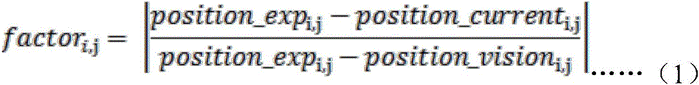
其中,factori,j是机器人在第j轮中,第i个目标位置的评价系数,position_expi,j为机器人在第j轮中第i个导航点的修正坐标,position_currenti,j为机器人在第j轮到达第i个导航点实测的当前坐标,position_visioni,j是通过视觉补偿定位算法计算到的视觉位置坐标。Among them, factor i, j is the evaluation coefficient of the i-th target position of the robot in the j-th round, position_exp i, j is the corrected coordinates of the i-th navigation point of the robot in the j-th round, and position_current i, j is the robot's position in the j-th round. The jth round reaches the measured current coordinates of the i-th navigation point, position_vision i, j is the visual position coordinates calculated by the visual compensation positioning algorithm.
关于目标位置的修正坐标的计算,以在长直走廊上预设11个导航目标点为例,进行说明:Regarding the calculation of the corrected coordinates of the target position, take the preset 11 navigation target points on the long straight corridor as an example to illustrate:
在长直走廊上预设11个导航目标点,每个导航点期望位置position_exp的初始值为position_exp0,position_exp0是在获取大量的实验数据后,通过求平均值的方式计算获得。机器人根据预设的目标位置,依次经过11个导航目标点,即表示机器人完成一轮寻址,机器人再依次经过11个导航目标点,即表示机器人完成第二轮寻址,以此类推。每完成一轮寻址,机器人就会对每个导航点的期望位置进行修正,用position_expi,j表示,其中,i表示导航点的编号,j表示机器人的寻址轮数,i=1,2,3…11,j=1,2,3…N。11 navigation target points are preset on the long straight corridor. The initial value of the desired position position_exp of each navigation point is position_exp 0 , and position_exp 0 is obtained by calculating the average value after obtaining a large amount of experimental data. According to the preset target position, the robot passes through 11 navigation target points in sequence, which means the robot completes one round of addressing, and the robot passes through 11 navigation target points in sequence, which means the robot completes the second round of addressing, and so on. Each time a round of addressing is completed, the robot will correct the expected position of each navigation point, which is represented by position_exp i, j , where i represents the number of the navigation point, j represents the number of addressing rounds of the robot, i=1, 2, 3...11, j=1, 2, 3...N.
修正机器人目标位置的坐标的计算公式如公式(2)所示:The calculation formula for correcting the coordinates of the target position of the robot is shown in formula (2):
position_expi,j=factori-1,j(position_expi,j-1-position_currenti,j)+position_currenti,j position_exp i,j =factor i-1,j (position_exp i,j-1- position_current i,j )+position_current i,j
……(2)……(2)
其中,i表示导航点的编号,j表示机器人的寻址轮数,position_expi,j是机器人在第j轮中第i个导航点的修正坐标,factori-1,j机器人第j轮到达第i-1个导航点计算出的评价系数,position_expi,j-1是第i个导航点在第j-1轮的修正坐标,position_currenti,j是机器人在第j轮到达第i个导航点实测的当前坐标。Among them, i represents the number of the navigation point, j represents the number of addressing rounds of the robot, position_exp i, j is the corrected coordinate of the i-th navigation point of the robot in the j-th round, factor i-1, j robot reaches the j-th round of the j-th round The evaluation coefficient calculated by the i-1 navigation point, position_exp i, j-1 is the corrected coordinate of the i-th navigation point in the j-1th round, position_current i, j is the robot reaching the i-th navigation point in the jth round The measured current coordinates.
显然上式为迭代式,利用该式可以在机器人每次定位时迭代消除机器人运行时产生的误差,从而实现机器人长时间多次的精确定位。Obviously, the above formula is an iterative formula, which can be used to iteratively eliminate the error generated by the robot during each positioning of the robot, so as to realize the precise positioning of the robot for a long time and many times.
其中,步骤S4中的视觉补偿定位算法是指:Wherein, the visual compensation positioning algorithm in step S4 refers to:
通过机器人平台搭载的可见光相机以及设置的标识物,可以相对准确的计算标识相对相机的位姿,从而计算出机器人当前的精确姿态(标识物的姿态已知)。Through the visible light camera mounted on the robot platform and the set marker, the pose of the marker relative to the camera can be relatively accurately calculated, thereby calculating the current precise pose of the robot (the pose of the marker is known).
相对距离计算根据相似三角形原理,通过相机CMOS感光元件与物体实际物理坐标系的小孔成像原理推算出相似三角公式,其中前后距离计算中涉及到像素焦距的概念,此为比例系数,各摄像机的参数值有所区别,需要单独测量计算得出,该系数涉及到CMOS尺寸,相机实际焦距,成像原理等众多相机参数的综合使用,需要拟定详细的相机标定计划并将其程序化,以便于使用和计算。计算公式如下:The relative distance calculation is based on the similar triangle principle, and the similar triangle formula is calculated through the imaging principle of the camera CMOS sensor and the actual physical coordinate system of the object. The concept of pixel focal length is involved in the calculation of the front and rear distance. The parameter values are different and need to be measured and calculated separately. This coefficient involves the comprehensive use of many camera parameters such as the CMOS size, the actual focal length of the camera, and the imaging principle. It is necessary to formulate a detailed camera calibration plan and program it for ease of use. and calculations. Calculated as follows:
1)左右距离计算公式如公式(3)所示,1) The left and right distance calculation formula is shown in formula (3),

其中,DistancetoCenter_Real是距离中心实际距离,WidthReal是标识物实际宽度,DistancetoCenter-Pixel是距离中心像素距离,WidthPixel是标识物像素宽度。Among them, Distance toCenter_Real is the actual distance from the center, Width Real is the actual width of the marker, Distance toCenter-Pixel is the distance from the center pixel, and Width Pixel is the pixel width of the marker.
2)前后距离计算公式如公式(4)所示,2) The calculation formula of the front and rear distance is shown in formula (4),

其中,Distance是相机距离标识物距离;FoucsPixel是像素焦距(比例系数),WidthReal是标识物实际宽度,WidthPixel是标识物像素宽度。Among them, Distance is the distance from the camera to the marker; Foucs Pixel is the pixel focal length (scale coefficient), Width Real is the actual width of the marker, and Width Pixel is the pixel width of the marker.
标识物的找寻主要基于如图4所示的二维码图形标识物,采取二维码能够有效避免环境中的干扰物的存在,并且二维码的规则形状可以提高计算准确度。其具体实现流程如图5所示,首先需要通过标定板对相机的内参进行标定,获取像素焦距,畸变系数矩阵等重要参数,然后利用Aruco函数库识别获取图像中的二维码的位置信息,通过相机内参进行相机坐标系与世界坐标系之间的转换,并计算可见光相机与标识物间的相对姿态关系,以进行调整操作。The search for markers is mainly based on the two-dimensional code graphic markers as shown in Figure 4. The two-dimensional code can effectively avoid the existence of interference in the environment, and the regular shape of the two-dimensional code can improve the calculation accuracy. The specific implementation process is shown in Figure 5. First, the internal parameters of the camera need to be calibrated through the calibration board to obtain important parameters such as pixel focal length and distortion coefficient matrix, and then use the Aruco function library to identify and obtain the location information of the QR code in the image. Conversion between the camera coordinate system and the world coordinate system is performed through the camera internal parameters, and the relative attitude relationship between the visible light camera and the marker is calculated for adjustment operations.
实施例中还包括一种室内自主导航机器人精确重复定位的系统,包括至少一个处理器,以及与至少一个处理器通信连接的存储器;存储器存储有可被至少一个处理器执行的指令,所述指令被至少一个处理器执行,以使至少一个处理器能够执行上述精确定位的方法。The embodiment also includes a system for accurate and repeated positioning of an indoor autonomous navigation robot, comprising at least one processor and a memory connected in communication with the at least one processor; the memory stores instructions executable by the at least one processor, the instructions Executed by at least one processor to enable the at least one processor to perform the above-described method for precise positioning.
Claims (6)
Priority Applications (1)
| Application Number | Priority Date | Filing Date | Title |
|---|---|---|---|
| CN201910805799.4A CN110488838B (en) | 2019-08-29 | 2019-08-29 | An accurate and repeatable positioning method for indoor autonomous navigation robot |
Applications Claiming Priority (1)
| Application Number | Priority Date | Filing Date | Title |
|---|---|---|---|
| CN201910805799.4A CN110488838B (en) | 2019-08-29 | 2019-08-29 | An accurate and repeatable positioning method for indoor autonomous navigation robot |
Publications (2)
| Publication Number | Publication Date |
|---|---|
| CN110488838A CN110488838A (en) | 2019-11-22 |
| CN110488838B true CN110488838B (en) | 2022-08-02 |
Family
ID=68553796
Family Applications (1)
| Application Number | Title | Priority Date | Filing Date |
|---|---|---|---|
| CN201910805799.4A Expired - Fee Related CN110488838B (en) | 2019-08-29 | 2019-08-29 | An accurate and repeatable positioning method for indoor autonomous navigation robot |
Country Status (1)
| Country | Link |
|---|---|
| CN (1) | CN110488838B (en) |
Families Citing this family (7)
| Publication number | Priority date | Publication date | Assignee | Title |
|---|---|---|---|---|
| CN111912431B (en) * | 2020-03-19 | 2021-05-11 | 中山大学 | Method for testing positioning accuracy of mobile robot navigation system |
| CN111766603B (en) * | 2020-06-27 | 2023-07-21 | 长沙理工大学 | Laser SLAM method, system, medium and equipment for mobile robot based on vision-assisted positioning of AprilTag code |
| CN113268063A (en) * | 2021-06-03 | 2021-08-17 | 北京京东乾石科技有限公司 | Control method and device for robot and non-volatile computer readable storage medium |
| CN113821047A (en) * | 2021-08-18 | 2021-12-21 | 杭州电子科技大学 | An autonomous landing method of unmanned aerial vehicle based on monocular vision |
| CN114623819B (en) * | 2022-03-21 | 2025-05-02 | 中国电信股份有限公司 | Robot positioning method, system, device, equipment and storage medium |
| CN114743244A (en) * | 2022-04-09 | 2022-07-12 | 合肥工业大学 | Physiological parameter and emotion detection method and system based on four-footed robot dog |
| CN119138187B (en) * | 2024-11-11 | 2025-08-19 | 莱克电气绿能科技(苏州)有限公司 | Solar charging type mowing robot and regression method thereof |
Citations (5)
| Publication number | Priority date | Publication date | Assignee | Title |
|---|---|---|---|---|
| KR20110081452A (en) * | 2010-01-08 | 2011-07-14 | 성균관대학교산학협력단 | Global Position Estimation and Correction Method of Mobile Robot Using Magnetic Landmarks |
| CN103308047A (en) * | 2013-05-10 | 2013-09-18 | 杭州师范大学 | Mobile robot positioning method with artificial on-line modification function |
| CN106969766A (en) * | 2017-03-21 | 2017-07-21 | 北京品创智能科技有限公司 | A kind of indoor autonomous navigation method based on monocular vision and Quick Response Code road sign |
| CN109163724A (en) * | 2018-09-07 | 2019-01-08 | 五邑大学 | Multiple target point autonomous navigation method based on Turtlebot2 robot building map |
| CN109739226A (en) * | 2018-12-27 | 2019-05-10 | 国网北京市电力公司 | Target inspection method for determining position and device |
Family Cites Families (1)
| Publication number | Priority date | Publication date | Assignee | Title |
|---|---|---|---|---|
| US10899015B2 (en) * | 2017-09-01 | 2021-01-26 | Siemens Aktiengesellschaft | Method and system for dynamic robot positioning |
-
2019
- 2019-08-29 CN CN201910805799.4A patent/CN110488838B/en not_active Expired - Fee Related
Patent Citations (5)
| Publication number | Priority date | Publication date | Assignee | Title |
|---|---|---|---|---|
| KR20110081452A (en) * | 2010-01-08 | 2011-07-14 | 성균관대학교산학협력단 | Global Position Estimation and Correction Method of Mobile Robot Using Magnetic Landmarks |
| CN103308047A (en) * | 2013-05-10 | 2013-09-18 | 杭州师范大学 | Mobile robot positioning method with artificial on-line modification function |
| CN106969766A (en) * | 2017-03-21 | 2017-07-21 | 北京品创智能科技有限公司 | A kind of indoor autonomous navigation method based on monocular vision and Quick Response Code road sign |
| CN109163724A (en) * | 2018-09-07 | 2019-01-08 | 五邑大学 | Multiple target point autonomous navigation method based on Turtlebot2 robot building map |
| CN109739226A (en) * | 2018-12-27 | 2019-05-10 | 国网北京市电力公司 | Target inspection method for determining position and device |
Also Published As
| Publication number | Publication date |
|---|---|
| CN110488838A (en) | 2019-11-22 |
Similar Documents
| Publication | Publication Date | Title |
|---|---|---|
| CN110488838B (en) | An accurate and repeatable positioning method for indoor autonomous navigation robot | |
| CN104200086B (en) | Wide-baseline visible light camera pose estimation method | |
| JP6760114B2 (en) | Information processing equipment, data management equipment, data management systems, methods, and programs | |
| CN106529587B (en) | Vision course recognition methods based on object detection | |
| CN110223355B (en) | Feature mark point matching method based on dual epipolar constraint | |
| CN114413958A (en) | Monocular vision distance and speed measurement method of unmanned logistics vehicle | |
| CN115717867B (en) | A bridge deformation measurement method based on airborne dual cameras and target tracking | |
| KR102490521B1 (en) | Automatic calibration through vector matching of the LiDAR coordinate system and the camera coordinate system | |
| CN108733039A (en) | The method and apparatus of navigator fix in a kind of robot chamber | |
| CN105809706B (en) | A kind of overall calibration method of the more camera systems of distribution | |
| CN103198481A (en) | Camera calibration method and achieving system of same | |
| CN113409396A (en) | Calibration method of ADAS monocular camera | |
| CN115760811B (en) | Method for measuring 6D pose of workpiece based on monocular vision and feature marks | |
| CN109782786A (en) | A kind of localization method and unmanned plane based on image procossing | |
| CN113781581B (en) | Depth of field distortion model calibration method based on target loose attitude constraint | |
| CN116358486A (en) | Target ranging method, device and medium based on monocular camera | |
| CN109087360A (en) | A kind of scaling method that robot camera is joined outside | |
| CN114777768B (en) | Satellite rejection environment high-precision positioning method and system and electronic equipment | |
| CN103685936A (en) | WIDE field of view camera image calibration and de-warping | |
| CN118424150B (en) | Measurement method, scanning device, and storage medium | |
| CN114373019A (en) | Method for calibrating camera without public view field by using optimization method | |
| CN115683102B (en) | Unmanned agricultural machinery navigation method, equipment, device and storage medium | |
| CN118864607A (en) | Method and computing system for calibrating external parameters of a camera mounted on a vehicle | |
| CN118229801A (en) | A method and device for calibrating camera and galvanometer position, striking and processing target aiming | |
| CN116563380B (en) | Butt joint correction method, butt joint correction device, butt joint device and computer equipment |
Legal Events
| Date | Code | Title | Description |
|---|---|---|---|
| PB01 | Publication | ||
| PB01 | Publication | ||
| SE01 | Entry into force of request for substantive examination | ||
| SE01 | Entry into force of request for substantive examination | ||
| GR01 | Patent grant | ||
| GR01 | Patent grant | ||
| CF01 | Termination of patent right due to non-payment of annual fee |
Granted publication date: 20220802 |