CN110476118B - Low Profile Multiband Hyperspectral Imaging for Machine Vision - Google Patents
Low Profile Multiband Hyperspectral Imaging for Machine Vision Download PDFInfo
- Publication number
- CN110476118B CN110476118B CN201780089074.9A CN201780089074A CN110476118B CN 110476118 B CN110476118 B CN 110476118B CN 201780089074 A CN201780089074 A CN 201780089074A CN 110476118 B CN110476118 B CN 110476118B
- Authority
- CN
- China
- Prior art keywords
- camera
- imaging system
- bandpass filters
- bandpass
- bandpass filter
- Prior art date
- Legal status (The legal status is an assumption and is not a legal conclusion. Google has not performed a legal analysis and makes no representation as to the accuracy of the status listed.)
- Active
Links
Images


Classifications
-
- G—PHYSICS
- G03—PHOTOGRAPHY; CINEMATOGRAPHY; ANALOGOUS TECHNIQUES USING WAVES OTHER THAN OPTICAL WAVES; ELECTROGRAPHY; HOLOGRAPHY
- G03B—APPARATUS OR ARRANGEMENTS FOR TAKING PHOTOGRAPHS OR FOR PROJECTING OR VIEWING THEM; APPARATUS OR ARRANGEMENTS EMPLOYING ANALOGOUS TECHNIQUES USING WAVES OTHER THAN OPTICAL WAVES; ACCESSORIES THEREFOR
- G03B11/00—Filters or other obturators specially adapted for photographic purposes
-
- G—PHYSICS
- G02—OPTICS
- G02B—OPTICAL ELEMENTS, SYSTEMS OR APPARATUS
- G02B26/00—Optical devices or arrangements for the control of light using movable or deformable optical elements
- G02B26/007—Optical devices or arrangements for the control of light using movable or deformable optical elements the movable or deformable optical element controlling the colour, i.e. a spectral characteristic, of the light
-
- G—PHYSICS
- G02—OPTICS
- G02B—OPTICAL ELEMENTS, SYSTEMS OR APPARATUS
- G02B5/00—Optical elements other than lenses
- G02B5/20—Filters
- G02B5/201—Filters in the form of arrays
-
- G—PHYSICS
- G03—PHOTOGRAPHY; CINEMATOGRAPHY; ANALOGOUS TECHNIQUES USING WAVES OTHER THAN OPTICAL WAVES; ELECTROGRAPHY; HOLOGRAPHY
- G03B—APPARATUS OR ARRANGEMENTS FOR TAKING PHOTOGRAPHS OR FOR PROJECTING OR VIEWING THEM; APPARATUS OR ARRANGEMENTS EMPLOYING ANALOGOUS TECHNIQUES USING WAVES OTHER THAN OPTICAL WAVES; ACCESSORIES THEREFOR
- G03B33/00—Colour photography, other than mere exposure or projection of a colour film
-
- G—PHYSICS
- G06—COMPUTING OR CALCULATING; COUNTING
- G06T—IMAGE DATA PROCESSING OR GENERATION, IN GENERAL
- G06T7/00—Image analysis
- G06T7/50—Depth or shape recovery
- G06T7/55—Depth or shape recovery from multiple images
-
- H—ELECTRICITY
- H04—ELECTRIC COMMUNICATION TECHNIQUE
- H04N—PICTORIAL COMMUNICATION, e.g. TELEVISION
- H04N23/00—Cameras or camera modules comprising electronic image sensors; Control thereof
- H04N23/10—Cameras or camera modules comprising electronic image sensors; Control thereof for generating image signals from different wavelengths
- H04N23/11—Cameras or camera modules comprising electronic image sensors; Control thereof for generating image signals from different wavelengths for generating image signals from visible and infrared light wavelengths
-
- H—ELECTRICITY
- H04—ELECTRIC COMMUNICATION TECHNIQUE
- H04N—PICTORIAL COMMUNICATION, e.g. TELEVISION
- H04N23/00—Cameras or camera modules comprising electronic image sensors; Control thereof
- H04N23/50—Constructional details
- H04N23/55—Optical parts specially adapted for electronic image sensors; Mounting thereof
-
- H—ELECTRICITY
- H04—ELECTRIC COMMUNICATION TECHNIQUE
- H04N—PICTORIAL COMMUNICATION, e.g. TELEVISION
- H04N23/00—Cameras or camera modules comprising electronic image sensors; Control thereof
- H04N23/90—Arrangement of cameras or camera modules, e.g. multiple cameras in TV studios or sports stadiums
-
- H—ELECTRICITY
- H04—ELECTRIC COMMUNICATION TECHNIQUE
- H04N—PICTORIAL COMMUNICATION, e.g. TELEVISION
- H04N5/00—Details of television systems
- H04N5/222—Studio circuitry; Studio devices; Studio equipment
- H04N5/262—Studio circuits, e.g. for mixing, switching-over, change of character of image, other special effects ; Cameras specially adapted for the electronic generation of special effects
- H04N5/265—Mixing
-
- G—PHYSICS
- G03—PHOTOGRAPHY; CINEMATOGRAPHY; ANALOGOUS TECHNIQUES USING WAVES OTHER THAN OPTICAL WAVES; ELECTROGRAPHY; HOLOGRAPHY
- G03B—APPARATUS OR ARRANGEMENTS FOR TAKING PHOTOGRAPHS OR FOR PROJECTING OR VIEWING THEM; APPARATUS OR ARRANGEMENTS EMPLOYING ANALOGOUS TECHNIQUES USING WAVES OTHER THAN OPTICAL WAVES; ACCESSORIES THEREFOR
- G03B15/00—Special procedures for taking photographs; Apparatus therefor
- G03B15/006—Apparatus mounted on flying objects
-
- G—PHYSICS
- G06—COMPUTING OR CALCULATING; COUNTING
- G06T—IMAGE DATA PROCESSING OR GENERATION, IN GENERAL
- G06T2207/00—Indexing scheme for image analysis or image enhancement
- G06T2207/10—Image acquisition modality
- G06T2207/10032—Satellite or aerial image; Remote sensing
- G06T2207/10036—Multispectral image; Hyperspectral image
Landscapes
- Physics & Mathematics (AREA)
- Engineering & Computer Science (AREA)
- General Physics & Mathematics (AREA)
- Multimedia (AREA)
- Signal Processing (AREA)
- Optics & Photonics (AREA)
- Computer Vision & Pattern Recognition (AREA)
- Theoretical Computer Science (AREA)
- Astronomy & Astrophysics (AREA)
- Spectroscopy & Molecular Physics (AREA)
- Studio Devices (AREA)
- Investigating Or Analysing Materials By Optical Means (AREA)
Abstract
提供了一种用于捕获成像数据的新颖的成像系统。根据所公开的实施例,成像系统包括一个或多个相机,该一个或多个相机被配置为捕获每个相机的视场内的相同场景。成像系统还包括多个带通滤波器,该多个带通滤波器可以定位在一个或多个相机的前面。每个带通滤波器可以允许入射电磁信号在不同的第一波长和第二波长对之间传输。因此,当带通滤波器定位在所述一个或多个相机的前面时,每个相机捕获不同的光谱图像,即仅包含在相机中被成像的相同场景的某些频率分量。通过相对于成像系统中的相机的位置旋转和/或平移带通滤波器,带通滤波器可以选择性地与一个或多个相机对准。
A novel imaging system for capturing imaging data is provided. According to the disclosed embodiments, an imaging system includes one or more cameras configured to capture the same scene within each camera's field of view. The imaging system also includes a plurality of bandpass filters, which may be positioned in front of the one or more cameras. Each bandpass filter may allow transmission of the incident electromagnetic signal between a different pair of first and second wavelengths. Thus, when the bandpass filter is positioned in front of the one or more cameras, each camera captures a different spectral image, ie contains only certain frequency components of the same scene imaged in the camera. The bandpass filter can be selectively aligned with one or more cameras by rotating and/or translating the bandpass filter relative to the position of the camera in the imaging system.
Description
版权声明Copyright Notice
本专利文件的公开内容的一部分包含受版权保护的材料。版权所有者虽然不反对任何人对本专利文件或专利公开内容进行复制,因为它出现在专利和商标局的专利文件或记录中,但是保留全部版权权利。A portion of the disclosure of this patent document contains material that is subject to copyright protection. The copyright owner has no objection to the facsimile reproduction by anyone of the patent document or the patent disclosure, as it appears in the Patent and Trademark Office patent file or records, but reserves all copyright rights whatsoever.
技术领域technical field
本发明总体上涉及成像系统,并且更具体地涉及多波段高光谱成像系统,其可以部署在各种系统中,如使用机器视觉的飞行器和空中平台、自主载运工具、船只或机器人。The present invention relates generally to imaging systems, and more particularly to multi-band hyperspectral imaging systems, which may be deployed in various systems such as aircraft and aerial platforms, autonomous vehicles, ships or robots using machine vision.
背景技术Background technique
已经使用红-绿-蓝(RGB)多波段成像系统来精确地捕获彩色图像。典型的RGB成像系统包括三个独立的图像传感器,每个图像传感器与相应的红色、绿色或蓝色光学滤波器匹配。当RGB相机捕获场景时,例如,对应于相机的视场中的图像,场景的图像由红色、绿色和蓝色滤波器分别进行滤波并由相机的图像传感器捕获。在三个颜色通道上产生的R、G和B滤波图像可以被加权和组合以更接近地类似于人眼将检测到的颜色光谱。因为计算机视觉系统没有人眼的光谱限制,所以需要能够精确地捕获人类视觉之外的光谱(例如,频率和频段)的新类型的成像系统。Red-green-blue (RGB) multi-band imaging systems have been used to accurately capture color images. A typical RGB imaging system includes three separate image sensors, each matched to a corresponding red, green, or blue optical filter. When an RGB camera captures a scene, eg, corresponding to an image in the camera's field of view, the image of the scene is filtered by red, green, and blue filters, respectively, and captured by the camera's image sensor. The R, G, and B filtered images produced on the three color channels can be weighted and combined to more closely resemble the color spectrum that the human eye would detect. Because computer vision systems do not have the spectral limitations of the human eye, new types of imaging systems that can accurately capture the spectrum (eg, frequencies and frequency bands) outside of human vision are needed.
与使用传统RGB相机可能提供的光谱信息相比,高光谱成像系统为成像场景提供更多光谱信息。相机的光谱响应范围通常是可以由相机的图像传感器检测的整个光谱,例如,该图像传感器可以是电荷耦合器件(CCD)传感器或互补金属半导体(CMOS)传感器。和RGB相机不同,高光谱成像系统在相机的整个光谱响应范围内捕获图像数据,并且与使用传统RGB相机可能提供的光谱分辨率和光谱波段相比,高光谱成像系统提供更好的光谱分辨率以及更明确和孤立的光谱波段。高光谱成像系统通常被分类为点扫描或线扫描系统或像素化涂层系统。如本文所使用的,高光谱成像系统不限于光谱波段的任何特定数量或分布,并且包括跨越不限于传统的RGB波段的多个不同光谱波段(例如,以频率或波长测量的)捕获图像的光谱数据的任何成像系统。Hyperspectral imaging systems provide more spectral information for the imaged scene than is possible using conventional RGB cameras. The spectral response range of a camera is typically the entire spectrum that can be detected by the camera's image sensor, which can be, for example, a Charge Coupled Device (CCD) sensor or a Complementary Metal Semiconductor (CMOS) sensor. Unlike RGB cameras, hyperspectral imaging systems capture image data over the entire spectral response range of the camera and provide better spectral resolution than is possible using conventional RGB cameras and spectral bands and more defined and isolated spectral bands. Hyperspectral imaging systems are generally classified as point-scan or line-scan systems or pixelated coating systems. As used herein, a hyperspectral imaging system is not limited to any particular number or distribution of spectral bands, and includes a spectrum that captures images across a number of different spectral bands (eg, measured in frequency or wavelength) that are not limited to traditional RGB bands data from any imaging system.
现有的高光谱成像系统具有若干缺点,这些缺点使得它们不适用于许多机器视觉应用。例如,这些高光谱系统由于它们的许多光学光谱部件以及它们的复杂的操作原理而庞大、复杂且昂贵。结果,当前的高光谱系统不适合消费者使用。Existing hyperspectral imaging systems suffer from several disadvantages that make them unsuitable for many machine vision applications. For example, these hyperspectral systems are bulky, complex and expensive due to their many optical spectral components and their complex operating principles. As a result, current hyperspectral systems are not suitable for consumer use.
此外,典型的点扫描或线扫描成像系统具有非常高的光谱分辨率(例如,约3nm)并且由于这种高光谱分辨率而花费过多的时间量来扫描相机的整个光谱响应范围(例如,400nm至1000nm)。相机所捕获的图像中的物体通常具有近似50nm或以上的特征和变化,其不需要在约3nm的较高的光谱分辨率下的处理。另外,因为图像传感器的空间分辨率通常与它们的光谱分辨率成反比,所以点扫描和线扫描成像系统的空间分辨率对于许多机器视觉应用来说是不够的。传统的像素化涂层系统类似地牺牲空间分辨率并且还具有需要复杂的光学器件用于成像的缺点,例如,因为它们使用单个光学透镜系统来对相同场景内的不同区域成像。Furthermore, typical point-scan or line-scan imaging systems have very high spectral resolution (eg, about 3 nm) and spend an excessive amount of time scanning the entire spectral response range of the camera due to this high spectral resolution (eg, 400nm to 1000nm). Objects in images captured by cameras typically have features and variations of approximately 50 nm or more, which do not require processing at the higher spectral resolution of about 3 nm. Additionally, because the spatial resolution of image sensors is generally inversely proportional to their spectral resolution, the spatial resolution of point-scan and line-scan imaging systems is insufficient for many machine vision applications. Traditional pixelated coating systems similarly sacrifice spatial resolution and also have the disadvantage of requiring complex optics for imaging, eg, because they use a single optical lens system to image different areas within the same scene.
需要一种改进的高光谱成像系统,该系统具有成本效益并且适用于消费产品诸如无人飞行器(UAV)的成像系统。高光谱系统应该适用于多种机器视觉应用,包括但不限于UAV、物体和模式识别、机器学习、材料分析、农业分析、食品分析、机器人学、自主驾驶以及坚持从使用高光谱相机系统的更便宜、更小、更不复杂的替代品中受益的任何其他系统。There is a need for an improved hyperspectral imaging system that is cost effective and suitable for imaging systems for consumer products such as unmanned aerial vehicles (UAVs). Hyperspectral systems should be suitable for a variety of machine vision applications, including but not limited to UAVs, object and pattern recognition, machine learning, materials analysis, agricultural analysis, food analysis, robotics, autonomous driving, and those that persist from using hyperspectral camera systems. Any other system that would benefit from a cheaper, smaller, less complex alternative.
发明内容SUMMARY OF THE INVENTION
本发明通过提供可用于机器视觉系统的新颖的高光谱成像系统和技术克服了现有技术的缺点,所述机器视觉系统包括但不限于可移动物体,诸如使用机器视觉的飞行器和空中平台、自主载运工具、船或机器人。与先前的实现方案不同,所公开的成像系统具有更高的空间分辨率,因为它们在对不同光谱波段中的图像进行滤波时可以使用相机的所有传感器像素。所公开的实施例还提供比传统RGB相机系统更好的光谱分辨率(例如,大约10到100nm),并且有利地,还提供实时、轻量和成本有效的解决方案。所公开的高光谱成像系统可以以相对低的成本大规模生产,促进机器人视觉和机器学习的进步。The present invention overcomes the shortcomings of the prior art by providing novel hyperspectral imaging systems and techniques useful in machine vision systems including, but not limited to, movable objects such as aircraft and aerial platforms using machine vision, autonomous Vehicle, boat or robot. Unlike previous implementations, the disclosed imaging systems have higher spatial resolution because they can use all of the camera's sensor pixels when filtering images in different spectral bands. The disclosed embodiments also provide better spectral resolution (eg, on the order of 10 to 100 nm) than conventional RGB camera systems, and, advantageously, also provide a real-time, lightweight, and cost-effective solution. The disclosed hyperspectral imaging system can be mass-produced at relatively low cost, facilitating advances in robotic vision and machine learning.
根据所公开的实施例,该成像系统包括一个或多个相机,每个相机具有相应的图像传感器,所述相机被配置为捕获每个相机的视场内的相同场景。该成像系统还包括多个带通滤波器,该多个带通滤波器可以定位在所述一个或多个图像传感器的前面。每个带通滤波器具有通带,该通带允许入射的电磁信号在与滤波器相关联的第一波长和第二波长之间传输。例如,该系统中的第一带通滤波器可以具有在500nm至550nm之间的通带,并且第二带通滤波器可以具有在不同的波长对例如610nm至640nm之间的通带。进一步对于所公开的实施例,每个带通滤波器具有不同的通带,其可以与系统中的其他滤波器的通带重叠,或可以不与系统中的其他滤波器的通带重叠。因此,当不同的带通滤波器定位在所述一个或多个图像传感器的前面时,所述一个或多个相机的每个图像传感器捕获不同的光谱图像,即仅包含在相机的视场中被成像的相同场景的某些频率分量。According to the disclosed embodiments, the imaging system includes one or more cameras, each camera having a corresponding image sensor, the cameras being configured to capture the same scene within each camera's field of view. The imaging system also includes a plurality of bandpass filters that may be positioned in front of the one or more image sensors. Each bandpass filter has a passband that allows incoming electromagnetic signals to pass between a first wavelength and a second wavelength associated with the filter. For example, a first bandpass filter in the system may have a passband between 500 nm and 550 nm, and a second bandpass filter may have a passband between a different wavelength pair, eg, between 610 nm and 640 nm. Further to the disclosed embodiments, each bandpass filter has a different passband, which may or may not overlap the passbands of other filters in the system. Thus, when a different bandpass filter is positioned in front of the one or more image sensors, each image sensor of the one or more cameras captures a different spectral image, ie only contained in the camera's field of view Certain frequency components of the same scene being imaged.
所公开的实施例不限于相机和带通滤波器之间的任何特定的物理配置。例如,多个相机可以布置成线性阵列或多维阵列,使得不同的带通滤波器可以定位在每个相机的前面。在其他所公开的实施例中,所述成像系统可以包括可旋转台,所述多个带通滤波器中的至少一些带通滤波器安装在所述可旋转台上。在这样的实施例中,旋转机构可以被配置为旋转所述可旋转台,使得所安装的带通滤波器中的至少一个带通滤波器与至少一个相机对准。在其他所公开的实施例中,所述成像系统可以包括:平移台,所述带通滤波器中的至少一些带通滤波器安装在所述平移台上;以及平移机构,所述平移机构被配置为在轴向方向上或沿着限定的路径例如在轨道上移动所述平移台,并使所安装的带通滤波器中的至少一个带通滤波器与至少一个相机对准。此外,所述带通滤波器可以定位在相机的图像传感器的前面,并且在一些实施例中可以定位成通过一个或多个其他部件,如至少一个光学透镜、偏振器或其他光学部件,与相机的传感器分开。The disclosed embodiments are not limited to any particular physical configuration between the camera and the bandpass filter. For example, multiple cameras can be arranged in a linear or multi-dimensional array so that different bandpass filters can be positioned in front of each camera. In other disclosed embodiments, the imaging system may include a rotatable stage on which at least some of the plurality of bandpass filters are mounted. In such an embodiment, the rotation mechanism may be configured to rotate the rotatable stage such that at least one of the mounted bandpass filters is aligned with the at least one camera. In other disclosed embodiments, the imaging system can include: a translation stage on which at least some of the bandpass filters are mounted; and a translation mechanism, the translation mechanism being The translation stage is configured to move the translation stage in an axial direction or along a defined path, eg, on a track, and to align at least one of the mounted bandpass filters with the at least one camera. Additionally, the bandpass filter may be positioned in front of the camera's image sensor, and in some embodiments may be positioned to communicate with the camera through one or more other components, such as at least one optical lens, polarizer, or other optical component sensors are separated.
所公开的实施例也不限于任何特定数量或类型的相机或带通滤波器。在一些实施例中,例如,相机可以包括至少一个灰度相机,诸如传统的CCD相机或CMOS相机。灰度相机可以包括CCD、滚动快门CMOS、全局快门CMOS,并且还可以包括非硅基相机,诸如红外相机或热感相机。所述多个带通滤波器可以包括单独的物理滤波器或具有光学涂层的单个滤波器,该光学涂层在滤波器上的不同区域处提供多个通带。The disclosed embodiments are also not limited to any particular number or type of cameras or bandpass filters. In some embodiments, the camera may comprise at least one grayscale camera, such as a conventional CCD camera or a CMOS camera, for example. Grayscale cameras may include CCD, rolling shutter CMOS, global shutter CMOS, and may also include non-silicon based cameras such as infrared cameras or thermal cameras. The plurality of bandpass filters may comprise separate physical filters or a single filter with an optical coating that provides multiple passbands at different regions on the filter.
根据所公开的实施例,滤波器的通带的带宽(例如,该带宽被测量为滤波器的第一波长和第二波长之间的差)可以在大约10nm至100nm之间,并且各个滤波器的带宽可以不同。在一些实施例中,带通滤波器中的每个带通滤波器都具有通过将相机的光谱响应范围(即,可由相机检测的波长的范围)除以带通滤波器的数量来确定的带宽。在这些示例性实施例中,每个带通滤波器具有相等的带宽,并且滤波器的通带共同覆盖相机的光谱响应的整个范围。在其他实施例中,可以通过仅将相机的光谱响应范围的一部分除以带通滤波器的数量来确定带通滤波器的通带。在其他实施例中,所述多个带通滤波器可以覆盖相机的光谱响应范围的不连续部分。According to the disclosed embodiments, the bandwidth of the passband of the filter (eg, the bandwidth measured as the difference between the first wavelength and the second wavelength of the filter) may be between approximately 10 nm and 100 nm, and each filter The bandwidth can be different. In some embodiments, each of the bandpass filters has a bandwidth determined by dividing the spectral response range of the camera (ie, the range of wavelengths detectable by the camera) by the number of bandpass filters . In these exemplary embodiments, each bandpass filter has an equal bandwidth, and the passbands of the filters collectively cover the entire range of the camera's spectral response. In other embodiments, the passband of the bandpass filter may be determined by dividing only a portion of the spectral response range of the camera by the number of bandpass filters. In other embodiments, the plurality of bandpass filters may cover discrete portions of the camera's spectral response range.
将会理解的是,前面的一般性描述和下面的详细描述都只是示例性和说明性的,并不是对要求保护的所公开的实施例的限制。例如,仅为了便于解释,本文描述的通带和光谱响应范围以波长表示。本领域的技术人员将理解,所公开的波长可以等效地表示为频率,并且本文描述的发明原理同样适用于波长或频率的背景。It is to be understood that both the foregoing general description and the following detailed description are exemplary and explanatory only and are not restrictive of the disclosed embodiments as claimed. For example, the passbands and spectral response ranges described herein are expressed in wavelengths for ease of explanation only. Those skilled in the art will understand that the disclosed wavelengths may be equivalently expressed as frequencies and that the inventive principles described herein are equally applicable in the context of wavelengths or frequencies.
附图说明Description of drawings
包含在本说明书中并构成本说明书的一部分的随附附图示出了所公开的实施例,并且与所述描述一起用于解释所公开的实施例。在附图中:The accompanying drawings, which are incorporated in and constitute a part of this specification, illustrate the disclosed embodiments and, together with the description, serve to explain the disclosed embodiments. In the attached image:
图1是根据所公开的实施例的被配置为与示例性第二物体通信的示例性可移动物体的示意图;1 is a schematic diagram of an exemplary movable object configured to communicate with an exemplary second object in accordance with the disclosed embodiments;
图2是可以根据所公开的实施例使用的示例性控制系统的示意性框图;2 is a schematic block diagram of an exemplary control system that may be used in accordance with the disclosed embodiments;
图3是可以在根据所公开的实施例的成像系统中使用的相机和带通滤波器的示意图;3 is a schematic diagram of a camera and bandpass filter that may be used in an imaging system according to disclosed embodiments;
图4是示出可以根据所公开的实施例使用的带通滤波器的示例性通带的曲线图;4 is a graph illustrating exemplary passbands of a bandpass filter that may be used in accordance with the disclosed embodiments;
图5是可以根据所公开的实施例使用的示例性相机阵列和相应的带通滤波器阵列的示意图;5 is a schematic diagram of an exemplary camera array and corresponding bandpass filter array that may be used in accordance with the disclosed embodiments;
图6是示出可以根据某些所公开的实施例使用的跨越相机的图像传感器的光谱响应范围的带通滤波器的多个示例性通带的曲线图;6 is a graph illustrating multiple exemplary passbands of a bandpass filter spanning the spectral response range of an image sensor of a camera that may be used in accordance with certain disclosed embodiments;
图7是可以根据某些所公开的实施例使用的、安装在可旋转台上的带通滤波器的示例性布置的示意图;以及7 is a schematic diagram of an exemplary arrangement of bandpass filters mounted on a rotatable stage that may be used in accordance with certain disclosed embodiments; and
图8是可以根据某些所公开的实施例使用的、在光学基板上的不同区域处形成并且可以安装在平移台上的带通滤波器的示例性布置的示意图。8 is a schematic diagram of an exemplary arrangement of bandpass filters formed at different regions on an optical substrate and mounted on a translation stage that may be used in accordance with certain disclosed embodiments.
具体实施方式Detailed ways
以下详细描述参考随附的附图。只要可能,在附图和以下描述中使用相同的附图标记来指代相同或相似的部分。虽然本文描述了几个说明性实施例,但是修改、改编和其他实现是可能的。例如,可以对附图中示出的部件进行替换、添加或修改,并且可以通过对所公开的方法进行替换、重新排序、移除或添加步骤来修改本文描述的说明性方法。因此,以下详细描述不限于所公开的实施例和示例。相反,适当的范围由所附权利要求限定。The following detailed description refers to the accompanying drawings. Wherever possible, the same reference numbers will be used throughout the drawings and the following description to refer to the same or like parts. While several illustrative embodiments are described herein, modifications, adaptations, and other implementations are possible. For example, components shown in the figures may be replaced, added, or modified, and the illustrative methods described herein may be modified by substituting, reordering, removing, or adding steps to the disclosed methods. Therefore, the following detailed description is not limited to the disclosed embodiments and examples. Rather, the appropriate scope is defined by the appended claims.
图1示出了可以被配置为在环境内移动的示例性可移动物体10。可移动物体10可以是被配置为在适当的介质(例如,表面、空气、水、一个或多个轨道、空间、地下等)上或内行进的任何适当的物体、装置、机构、系统或机器。例如,可移动物体10可以是无人飞行器(UAV)。尽管出于本描述的示例性目的,可移动物体10在本文中被示出并描述为UAV,但应理解其他类型的可移动物体(例如,轮式物体、航海物体、机车物体、其他空中物体、飞行器、空中平台、自主载运工具、船、机器人等)也可以或替代性地在与本公开内容一致的实施例中使用。如本文所使用的,术语UAV可以指代被配置为自动地(例如,通过电子控制系统)和/或由场外人员手动地操作和/或控制的空中装置。FIG. 1 shows an exemplary
可移动物体10可以包括壳体11、一个或多个推进组件12、以及诸如一个或多个相机系统之类的有效载荷14。在一些实施例中,如图1所示,有效载荷14可以通过载体16连接或附接到可移动物体10,该载体可以允许有效载荷14和可移动物体10之间的一个或多个相对移动度。在其他实施例中。有效载荷14可以在没有载体16的情况下直接安装到可移动物体10。可移动物体10还可以包括电力存储装置18、通信装置20和与其他部件通信的电子控制单元22。在一些实施例中,电力存储装置18、通信装置20和电子控制单元22中的一个或多个可以被包括在控制系统23中。控制系统23可以被配置为控制可移动物体10的多个系统或功能。替代性地,控制系统23可以专用于控制单个系统或功能子集。例如,控制系统23可以是UAV的飞行控制系统或包括UAV的飞行控制系统,其允许采取方法控制有效载荷14。The
可移动物体10可以包括定位在不同位置(例如,可移动物体10的顶部、侧面、前面、后面和/或底部)用于推动和转向可移动物体10的一个或多个推进组件12。尽管图1中仅示出了两个示例性推进组件12,但是将理解的是,可移动物体10可以包括任何数量的推进组件(例如,1、2、3、4、5、10、15、20个等)。推进组件12可以是可操作以产生用于支撑受控飞行的力的装置或系统。推进组件12可以共用或者可以各自单独地包括至少一个电源,诸如一个或多个电池、燃料电池、太阳能电池等、或它们的组合。每个推进组件12还可以包括一个或多个旋转部件24,例如,在电机、引擎或涡轮机内,耦接到电源并被配置为参与产生用于支撑受控飞行的力。例如,旋转部件24可以包括旋翼、螺旋桨、叶片等,其可以在被配置为从电源传递电力的轴、轮轴、轮或其他部件或系统上被驱动或被所述轴、轮轴、轮或其他部件驱动。推进组件12和/或旋转部件24可以相对于彼此和/或相对于可移动物体10是可调整的(例如,可倾斜的)。替代性地,推进组件12和旋转部件24可以具有相对于彼此和/或相对于可移动物体10的固定取向。在一些实施例中,每个推进组件12可以是相同类型的。在其他实施例中,推进组件12可以具有多种不同类型。在一些实施例中,可以协同控制所有推进组件12(例如,全都处于相同的速度和/或角度)。在其他实施例中,可以关于例如速度和/或角度独立地控制一个或多个推进装置。The
推进组件12可以被配置为在一个或多个竖直方向和水平方向上推进可移动物体10并且允许可移动物体10绕一个或多个轴线旋转。也就是说,推进组件12可以被配置为提供用于产生和维持可移动物体10的平移运动和旋转运动的升力和/或推力。例如,推进组件12可以被配置为使得可移动物体10能够实现和维持期望的高度、提供在所有方向上移动的推力并且提供可移动物体10的转向。在一些实施例中,推进组件12可以使得可移动物体10能够执行竖直起飞和着陆(即,没有水平推力的起飞和着陆)。在其他实施例中,可移动物体10可能需要恒定的最小水平推力以实现和支撑飞行。推进组件12可以配置为使得可移动物体10能够沿着多个轴线和/或绕多个轴线移动。
有效载荷14可以包括一个或多个传感装置19,诸如图1所示的示例性传感装置19。传感装置19可以包括成像系统25。传感装置19可以包括用于采集或产生数据或信息的装置,诸如勘测、跟踪和捕获目标的图像或视频(例如,物体、风景、照片或视频拍摄的对象等)的装置。传感装置19可以包括被配置为收集可以用于产生图像的数据的一个或多个成像装置。例如,成像装置可以包括照相机(例如,模拟、数字相机等)、视频相机、红外成像装置、紫外成像装置、x射线装置、超声波成像装置、雷达装置、双目相机等。在一些实施例中,如下面进一步描述的,传感装置19可以包括一维或多维相机阵列和多个带通滤波器。传感装置图19还可以包括用于捕获音频数据的装置,诸如麦克风或超声波检测器。传感装置19还可以或替代性地包括用于捕获视觉、音频和/或电磁信号的其他适当的传感器。The
载体16可以包括被配置为保持有效载荷14和/或允许相对于可移动物体10调整(例如,旋转)有效载荷14的一个或多个装置。例如,载体16可以是云台。如下所述,载体16可以被配置为允许有效载荷14绕一个或多个轴线旋转。在一些实施例中,载体16可以被配置为允许绕每个轴线旋转360°以允许更大程度地控制有效载荷14的视角。在其他实施例中,载体16可以将有效载荷14绕其轴线中的一个或多个的旋转范围限制为小于360°(例如,≤270°、≤210°、≤180°、≤120°、≤90°、≤45°、≤30°、≤15°等)。
通信装置20可以被配置为实现电子控制单元22与场外实体之间的数据、信息、命令(例如,飞行命令、用于操作有效载荷14的命令等)和/或其他类型的信号的通信。通信装置20可以包括被配置为发送和/或接收信号的一个或多个部件,诸如被配置为执行单向通信或双向通信的接收器、发射器或收发器。通信装置20的部件可以被配置为通过一个或多个通信网络,诸如被配置用于WLAN、无线电、蜂窝(例如,WCDMA、LTE等)、WiFi、RFID等的网络,并且使用一个或多个无线通信协议(例如,IEEE 802.15.1、IEEE 802.11等)和/或可用于传输指示数据、信息、命令、控制和/或其他信号的信号的其他类型的通信网络或协议,与场外实体通信。通信装置20可以被配置为实现与用户输入装置诸如控制终端(例如,远程控件)或其他固定、移动或手持控制装置的通信,该用户输入装置提供用于在飞行期间控制可移动物体10的用户输入。例如,通信装置20可以被配置为与第二物体26通信,该第二物体可以是用户输入装置或能够利用可移动物体10接收和/或传输信号的任何其他装置。
第二物体26可以是固定装置、移动装置或被配置为通过通信装置20与可移动物体10通信的其他类型的装置。例如,在一些实施例中,第二物体26可以是另一可移动装置(例如,另一个UAV)、计算机、终端、用户输入装置(例如,远程控制装置)等。第二物体26可以包括通信装置28,该通信装置被配置为实现与可移动物体10(例如,与通信装置20)或其他物体的无线通信。通信装置28可以被配置为从通信装置20接收数据和信息,诸如与例如位置数据、速度数据、加速度数据、传感数据(例如,成像数据)有关的操作数据,以及与可移动物体10、其部件和/或其周围环境有关的其他数据和信息。在一些实施例中,第二物体26可以包括控制特征,诸如控制杆、按钮、触摸屏装置、显示器等。在一些实施例中,第二物体26可以体现为具有虚拟控制特征(例如,图形用户界面、应用程序等)的电子通信装置,诸如智能电话或平板电脑。The
图2是示出根据所公开的实施例的示例性控制系统23和第二物体26的示意性框图。控制系统23可以包括电力存储装置18、通信装置20和电子控制单元22等。第二物体26尤其可以包括通信装置28和电子控制单元30。FIG. 2 is a schematic block diagram illustrating an exemplary control system 23 and
电力存储装置18可以是被配置为给可移动物体10中的电子部件、机械部件或它们的组合供电或以其他方式供应电力的装置。例如,电力存储装置18可以是电池、电池组或其他装置。在其他实施例中,电力存储装置18可以是或包括可燃燃料、燃料电池或另一类型的电力存储装置中的一个或多个。
通信装置20可以是被配置为实现与其他装置的无线通信的电子装置,并且可以包括发射器32、接收器34、电路和/或其他部件。发射器32和接收器34可以是分别配置为发射和接收无线通信信号的电子部件。在一些实施例中,发射器32和接收器34可以是单独的装置或结构。替代性地,发射器32和接收器34可以组合(或者它们的相应功能可以组合)在被配置为发送(即,发射)和接收无线通信信号的单个收发器装置中,该无线通信信号可以包括用数据或信息编码或以其他方式指示数据或信息的任何类型的电磁信号。发射器32和接收器34可以连接到一个或多个共用天线,诸如图2中的示例性天线,或者可以使用可移动物体10中的单独天线或天线阵列进行发射和接收。
通信装置20可以被配置为通过可用于向电子控制单元22传递数据和信息或从电子控制单元传递数据和信息的适当的通信手段传输数据和/或从一个或多个其他装置接收数据。例如,通信装置20可以被配置为利用一个或多个局域网(LAN)、广域网(WAN)、红外系统、无线电系统、Wi-Fi网络、点到点(P2P)网络、蜂窝网络、卫星网络等。可选地,可以使用中继站,诸如塔、卫星或移动站,以及促进可移动物体10与第二物体26之间的通信的任何其他中间节点。无线通信可以是依赖于接近度的,或与接近度无关的。在一些实施例中,通信可能需要视线或可能不需要视线。
电子控制单元22可以包括一个或多个部件,包括例如存储器36和至少一个处理器38。存储器36可以是或包括非暂时性计算机可读介质,并且可以包括非暂时性计算机可读介质的一个或多个存储单元。存储器36的非暂时性计算机可读介质可以是或包括任何类型的易失性或非易失性储器,包括但不限于软盘、硬盘、光盘、DVD、CD-ROM、微驱动器、磁光盘、ROM、RAM、EPROM、EEPROM、DRAM、VRAM、闪速存储器装置、磁卡或光卡、纳米系统(包括分子存储器集成电路)、或者适用于存储指令和/或数据的任何其它类型的介质或装置。存储器单元可以包括非暂时性计算机可读介质的永久部分和/或可移除部分(例如,可移动介质或外部储存器,诸如SD卡、RAM等)。
来自传感装置19和/或其他装置的信息和数据可以被传送到并存储在存储器36的非暂时性计算机可读介质中。与存储器36相关联的非暂时性计算机可读介质也可以被配置为存储能够由处理器38执行以执行本文描述的说明性实施例中的任一个的逻辑、代码和/或程序指令。例如,与存储器36相关联的非暂时性计算机可读介质可以被配置为存储计算机可读指令,该计算机可读指令在由处理器38执行时,使处理器执行包括一个或多个步骤的方法。由处理器38基于存储在存储器36的非暂时性计算机可读介质中的指令执行的方法可以涉及处理输入,诸如存储在存储器36的非暂时性计算机可读介质中的数据或信息的输入、从第二物体26接收的输入、从传感装置19接收的输入、和/或通过通信装置20接收的其他输入。非暂时性计算机可读介质可以被配置为存储从传感装置19获得或得出的数据以由处理器38和/或第二物体26(例如,通过电子控制单元30)处理。在一些实施例中,非暂时性计算机可读介质可以用于存储由处理器38产生的处理结果。Information and data from sensing device 19 and/or other devices may be transferred to and stored in a non-transitory computer-readable medium of
处理器38可以包括一个或多个处理器,并且可以体现为可编程处理器,诸如,中央处理单元(CPU)。处理器38可以可操作地耦接到被配置为存储能够由处理器38执行的程序或指令的存储器36或另一存储装置,以执行一个或多个方法步骤。注意,本文描述的方法步骤可以通过存储在存储器36中并且使得在由处理器38处理时执行该方法步骤的一个或多个指令和数据来体现。Processor 38 may include one or more processors, and may be embodied as a programmable processor, such as a central processing unit (CPU). The processor 38 may be operably coupled to the
在一些实施例中,处理器38可以包括一个或多个控制模块或替代性地可以可操作地耦接到一个或多个控制模块,诸如下面进一步描述的图2的说明性实施例中的通信模块40和飞行控制模块42。通信模块40可以被配置为帮助控制可移动物体10与其他物体(例如,第二物体26)之间的无线通信的方面,诸如通信装置20的传输功率水平。飞行模块42可以被配置为帮助控制可移动物体10的推进组件12,以在飞行期间调整可移动物体10的位置、朝向、速度和/或加速度。通信模块40和飞行控制模块42可以被实施成用于在处理器38上执行的软件,或者可以被实施成至少部分地包括在处理器38中或与处理器分离的硬件和/或软件部件。例如,通信模块40和飞行控制模块42可以包括被配置为实施它们各自的功能的一个或多个CPU、ASIC、DSP、FPGA、逻辑电路等,或者可以共享处理器38中的处理资源。如本文所使用的,术语“被配置为”应被理解为包括硬件配置、软件配置(例如,编程)及它们的组合,包括当与本文描述的任何控制器、电子控制单元或模块结合使用时或用于描述本文描述的任何控制器、电子控制单元或模块时。In some embodiments, processor 38 may include or alternatively may be operably coupled to one or more control modules, such as communications in the illustrative embodiment of FIG. 2 described further below module 40 and flight control module 42 . Communication module 40 may be configured to help control aspects of wireless communication between
可以以任何适当的配置来布置电子控制单元22的部件。例如,电子控制单元22的部件中的一个或多个可以定位在与电子控制单元的部件中的一个或多个通信的可移动物体10、载体16、有效载荷14、第二物体26、传感装置19或附加外部装置上。在一些实施例中,一个或多个处理器或存储装置可以位于不同的位置处,诸如可移动物体10、载体16、有效载荷14、第二物体26、传感装置19上或附加外部装置上,它们与上述电子控制单元的部件中的一个或多个或其适当的组合进行通信,使得由系统执行的处理和/或存储功能的任何适当的方面可以在前述位置中的一个或多个位置处发生。The components of
第二物体26可以包括在结构和/或功能上与控制系统23相同或相似的部件。例如,第二物体26的通信装置28可以包括发射器33和接收器35。发射器33和接收器35可以在结构和/或功能上分别与发射器32和接收器34相同或相似,因此将不再详细描述。第二物体26的电子控制单元30可以在结构(例如,可以包括存储器、处理器、模块等)和/或功能上与电子控制单元22相同或相似,因此将不再详细描述。The
控制系统23可以接收与可移动物体10的飞行参数有关的信息(“飞行状态信息”或“状态信息”)。状态信息可以包括指示可移动物体的移动和位置中的至少一个的信息,例如,当可移动物体10在飞行中或在静止时。例如,状态信息可以包括可移动物体10的速度、加速度、航向或高度(例如,地面上高度、海拔等)中的一个或多个,但不限于此,并且可以包括其他信息或附加信息。可以通过包括在控制系统23中、与控制系统连接或以其他方式与控制系统相关联的一个或多个传感器44来检测或采集状态信息。为简单起见,图2中仅示出了一个示例性传感器44。传感装置19中可以包括至少一个传感器44。传感器44可以包括例如陀螺仪、加速度计、压力传感器(例如,绝对压力传感器、差分压力传感器等)以及一个或多个(例如,多个)测距传感器,其可以包括一个或多个相机、红外装置、紫外装置、x射线装置、超声波装置、雷达装置、激光装置和与定位系统(例如,全球定位系统(GPS)、GLONASS、Galileo、Beidou、GAGAN、GNSS等)相关联的装置。测距传感器可以被配置为产生指示其自身与其他物体(例如,第二物体26)、地面等之间的距离的信号。传感器44可以包括其他传感器或附加传感器,诸如温度传感器(例如,温度计、热电偶等)、运动传感器、惯性测量传感器、距离传感器、图像传感器等。The control system 23 may receive information related to the flight parameters of the movable object 10 ("flight status information" or "status information"). The state information may include information indicative of at least one of movement and position of the movable object, eg, when the
图3是可以根据所公开的实施例使用的相机50和带通滤波器60的示例性配置的示意图。说明性的相机50和带通滤波器60可以安装在可移动物体10的有效载荷14之中。替代性地,相机和带通滤波器可以安装在可移动物体10上的允许操作如本文所述的高光谱成像系统25的任何其他位置上。相机50和带通滤波器60可以具有任何形状或形式,并且不限于图3所示的形状、大小和形式。FIG. 3 is a schematic diagram of an exemplary configuration of
可以使用本领域中已知的各种类型的相机来实现相机50。与先前的高光谱成像系统不同,所公开的实施例可以使用更低成本和更小形状因子的CCD和CMOS类型的相机和相关的光学部件。例如,相机50可以是灰度相机或提供所捕获的图像的亮度或强度信息的另一种类型的相机。相机50可以是没有任何彩色滤波器(例如,拜耳滤波器)的灰度相机。虽然相机50可以捕获可见光谱中的光学图像,但是它也可以基于可见光谱之外的电磁信号来捕获图像。在一些实施例中,例如,相机50可以捕获与红外波、热波、紫外波、x射线、伽马射线、微波、无线电波等对应的电磁信号。相机50可以捕获在其图像传感器58的光谱响应范围内的电磁频谱的任何部分中的图像。
在一些所公开的实施例中,相机50可以是全局快门相机(例如,其中曝光时间由机械快门确定),而在其他实施例中,相机50可以是滚动快门相机(例如,其中曝光时间由控制单元22中的软件和/或硬件确定)。例如,相机50可以是滚动快门CCD相机、滚动快门CMOS相机、全局快门CCD相机等。在其他实施例中,相机50可以包括硅基图像相机、红外相机或热感相机。在其他可能的实施例中,相机50可以包括非硅基相机,诸如铟-镓-砷化物(InGaAs)相机或汞镉-碲化物(HgCdTe)相机,例如,其中半导体带隙的波长从约0.8微米至约10微米。In some disclosed embodiments,
相机50包括至少一个图像传感器58。图像传感器可以是CCD传感器、CMOS传感器或能够检测在传感器的光谱响应范围内的入射电磁信号的非硅基传感器。例如,图像传感器58可以是光谱响应范围在大约400nm至大约1000nm之间的CMOS或CCD传感器。图像传感器58可以被配置为用于灰度相机。在一些实施例中,图像传感器58可以与其他传感器诸如红外传感器、热传感器等组合。在其他实施例中,图像传感器58可以包括视频图形阵列(VGA)传感器。
在一些所公开的实施例中,图像传感器58包括像素阵列,该像素阵列被配置为捕获与相机的视场中的图像对应的入射电磁信号。例如,图像传感器58可以将入射电磁信号转换为可以存储在存储器36中和/或由处理器38处理的数字数据阵列。在一些实施例中,图像传感器58中的每个像素都可以生成入射图像的一部分的模拟表示(样本),并且相机50可以包括将每个像素的模拟样本转换为数字表示的模数转换器(未示出)。In some disclosed embodiments, image sensor 58 includes an array of pixels configured to capture incident electromagnetic signals corresponding to images in the camera's field of view. For example, image sensor 58 may convert incident electromagnetic signals into an array of digital data that may be stored in
一个或多个部件,诸如光学透镜和/或偏振器,可以定位在相机的图像传感器58和带通滤波器60之间。在图3的示例性实施例中,例如,相机50包括成像透镜56,该成像透镜可以有助于将入射图像聚焦到图像传感器58中的像素阵列上。在其他实施例中,相机50可以包括多个成像透镜56,或者替代性地,根本不包括成像透镜。在其他实施例中,相机50可以包括偏振滤波器以增加图像传感器58上的空间识别。在一些所公开的实施例中,相机50(和图像传感器58)不包括任何传统的红色、绿色、蓝色(RGB)滤波器。One or more components, such as optical lenses and/or polarizers, may be positioned between the camera's image sensor 58 and the
与现有的高光谱成像系统中使用的透镜相比,示例性成像透镜56可以具有更小的轮廓(例如,形状因子和/或厚度)。例如,与现有技术系统相比,较小的成像透镜56可以减小相机50的宽度。而且,在一些实施例中,相机50可以具有相对大的光圈(例如,大于针孔),并且在其他实施例中,相机50可以具有与针孔相同大小或比针孔小的光圈。在一些实施例中,相机的光圈的大小可以是可调整的。The exemplary imaging lens 56 may have a smaller profile (eg, form factor and/or thickness) than lenses used in existing hyperspectral imaging systems. For example, a smaller imaging lens 56 may reduce the width of
带通滤波器60可以放置在相机50的前面。带通滤波器60包括有源滤波区域62,例如,在有源滤波区域62中对入射电磁信号(其可以包括但不限于可见光)进行滤波。滤波区域62适于仅通过预定通带中的某些频率(例如,具有在第一波长和第二波长之间的波长)。在所公开的实施例中,带通滤波器60被定位成使得通过滤波区域62(并且还可能通过一个或多个成像透镜56)的信号变为入射在图像传感器58上。尽管图3将示例性带通滤波器60示出为相对于相机50的单独模块,但是本领域的技术人员将理解,带通滤波器60替代性地可以附接到相机50或者以其他方式位于与相机共同的组件内。例如,带通滤波器60可以定位在共同的相机组件中的图像传感器58和成像透镜56之间,或者更一般地可以定位在图像传感器58前面的任何位置。
滤波区域62可以覆盖带通滤波器60的整个区域,或者替代性地,可以仅覆盖带通滤波器60的整个区域的子集。在一些实施例中,带通滤波器60可以包含多个滤波区域62,每个滤波区域具有不同的相应的通带,在这种情况下,每个滤波区域62可以用作具有其自己的通带的不同的带通滤波器。在一些实施例中,带通滤波器60包括例如沿轴线(线性地)定位或者以多维阵列布置或者以任何其他图案布置在带通滤波器60上的多个非重叠的滤波区域62。在这样的实施例中,每个滤波区域62具有允许某些波长的电磁信号通过该滤波区域的不同的通带。在一些实施例中,带通滤波器60可以包括阻带滤波器(未示出),该阻带滤波器阻挡某些波长的电磁信号通过滤波区域62。在一些实施例中,滤波区域62可以包括在带通滤波器60的不同区域处提供不同的通带的光学涂层和材料。实际上,带通滤波器60上的每个滤波区域62可以被不同地涂覆,以提供用于对入射电磁信号进行滤波的期望的通带和/或阻带。The
附加光学部件(图3中未示出)也可以定位在带通滤波器60的后面或前面。如下面更详细地讨论的,带通滤波器60可以安装在可移动台上,例如,该可移动台的位置由处理器38或控制系统23中的另一个控制器控制。即,处理器38可以指示包括带通滤波器60的可移动台相对于相机50的位置平移和/或旋转带通滤波器60,并且使带通滤波器60与相机中的光圈和/或图像传感器58对准。Additional optics (not shown in FIG. 3 ) may also be positioned behind or in front of the
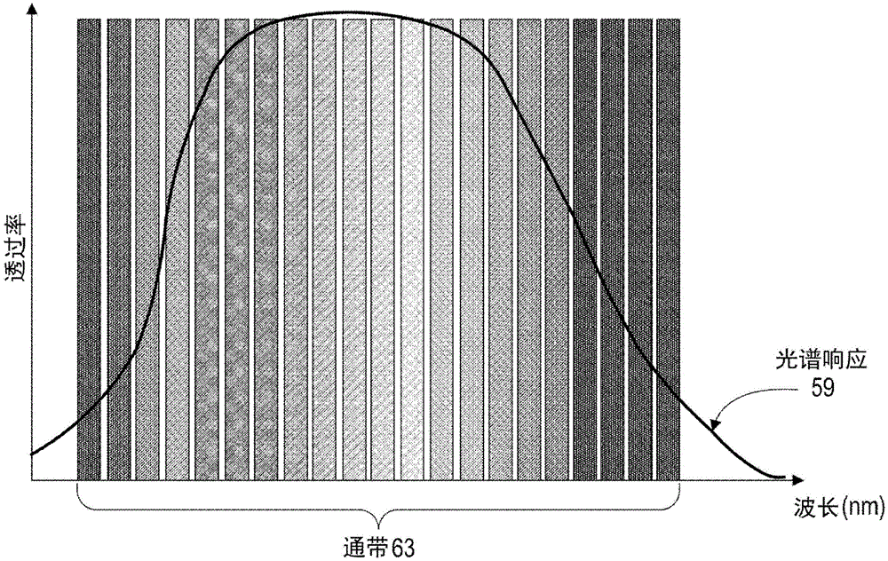
图4是示出滤波区域62的示例性通带63的曲线图。在图4中,入射电磁信号的透过率被绘制为入射波长的函数。带通滤波器的通带63对应于那些被许可传输通过滤波区域62而没有显著衰减的电磁信号。如示例性图4所示,通带63与具有在第一波长64和第二波长65之间的波长的入射信号对应,该第一波长和第二波长例如仅为了说明的目的而被示出为大约500nm和550nm。通带63的带宽66可以被确定为波长64和65之间的差。在一些实施例中,如示例性图4所示,带宽66可以近似为通带的半最大值全宽度。替代性地,可以通过本领域的技术人员理解的任何其他手段或测量来确定通带63的下波长(或频率)64和上波长65。优选地,带宽66在约10nm至约100nm之间,例如约30nm。然而,在其他实施例中,带宽66可以小于10nm或大于100nm。FIG. 4 is a graph showing an
图5是可以根据某些所公开的实施例使用的相机50和带通滤波器60的二维阵列的示意性框图。图5中所示的相机和滤波器的布置是示例性的,因为在所公开的实施例中可以存在任何数量和布置的相机50,以及任何数量和布置的带通滤波器60。在一些实现中,可以存在比相机50更多的带通滤波器60,或反之亦然,只要每个相机50具有定位在其前面的带通滤波器60以对入射信号进行滤波。根据实现,相机50和/或带通滤波器60替代性地可以布置成一维阵列或三维阵列。优选地,每个相机50都是包含相同类型的图像传感器58的相同类型的相机。例如,每个相机50可以是由相同制造商制造的相同相机型号。5 is a schematic block diagram of a two-dimensional array of
进一步对于所公开的实施例,每个相机50都被配置为捕获该相机的视场内包括相同场景的图像。在图5的示例性实施例中,相机阵列90中的每个相机50都位于固定位置处,并且带通滤波器60位于与相机阵列对准的滤波器阵列95中的对应的固定位置处,因此入射电磁信号在被每个相机检测到之前被滤波。在一些实施例中,相机50可以被配置为在同一时间或大约同时捕获图像。还可以控制相机50以任何其他顺序诸如顺序地或以随机或定时间隔捕获场景的图像。在一些实施例中,仅可以使用相机50的子集来捕获相同场景的图像。替代性地,单个相机50可以捕获场景的多个图像,例如,当不同的带通滤波器60顺序地定位在相机50的前面时,允许相机50捕获相同场景的不同光谱图像。Further to the disclosed embodiments, each
在所公开的实施例中,每个滤波器60都具有不同的通带63。在一些实施例中,带通滤波器60的通带63可以是不重叠的,因此每个相机50捕获相同场景在不同光谱范围内的图像(光谱图像)。在其他实施例中,带通滤波器的通带63中的至少一个通带可以与成像系统25中的另一个带通滤波器60的通带重叠。可以例如使用处理器38或另一处理器来处理由相机50捕获的光谱图像的至少一部分,以重建场景的图像、识别场景中的某些特征或物体,或者用于可以对相同场景的不同光谱图像进行操作的任何其他图像处理功能或例程。在一些实施例中,控制系统23可以关联由相机50捕获的光谱图像中的对应像素以创建合成图像。由相机捕获的光谱图像和任何导出的合成图像可以存储在存储器36中,并且在一些实施例中,可以与从传感装置19获得的其他相关信息诸如位置信息一起被存储。In the disclosed embodiment, each
图6是示出根据某些所公开的实施例的示例性实施例的曲线图,在该示例性实施例中,多个带通滤波器的通带63跨越相机中的图像传感器58的整个光谱响应范围59。示例性光谱响应范围59可以对应于相机50中的一个或多个相机。例如,光谱响应范围可以对应于具有CMOS或CCD传感器的图像传感器58,其光谱响应范围为从大约400nm至1000nm。当然,根据所公开的实施例,可以使用其他光谱响应范围。FIG. 6 is a graph illustrating an exemplary embodiment in which the
在一些实施例中,通带63的带宽66是相同的,并且通过将整个光谱响应范围59或光谱响应范围的任何部分除以带通滤波器60的数量来确定该带宽。如果带通滤波器60中的任何带通滤波器都具有多个滤波区域62,则可以通过将整个光谱响应范围59或光谱响应范围的任何部分除以滤波区域62的数量来确定通带63的带宽66。在这样的实施例中,光谱响应范围59(或其一部分)可以由不同的通带63均等地划分。在其他所公开的实施例中,相邻的通带63可以由不在滤波器的该通带中的任一个内的波长“防护带”分开。在其他实施例中,可以选择通带63以覆盖光谱响应范围59中的至少一个不连续波长范围。为了举例说明,光谱响应范围59可以在400nm至1000nm之间,其中通带63中没有任何通带被配置为对在500nm至525nm之间的波长范围进行滤波。In some embodiments, the
图7是根据某些所公开的实施例的示例性可旋转台70的示意图,可旋转台70具有旋转机构75,多个带通滤波器60安装在该旋转机构上。在该示例中,可旋转台是轮,多个带通滤波器60安装在该轮上的固定位置。图7中的该实现方案仅仅是示例性的,并且本领域的技术人员将理解,根据所公开的实施例,其他实现方案也是可以的。在一些实施例中,可旋转台70可以进一步安装在一个或多个可调整的平移台(未示出)上,以实现可旋转台70上的滤波区域62与成像系统25中的相机50的一个或多个图像传感器58和/或光圈的更精确的对准。旋转机构75可以由处理器38控制,或由使其上安装有带通滤波器60的可旋转台70旋转的任何其他处理器控制,以使带通滤波器60中的一个或多个带通滤波器与成像系统25中的相机50对准。7 is a schematic diagram of an exemplary rotatable stage 70 having a
在一些实施例中,旋转机构75可以包括将使带通滤波器60在成像系统中的一个或多个相机50前面旋转的轮系统、齿轮系统、滑轮系统或任何其他系统中的一个或多个系统。在一些实施例中,旋转机构75能够在多个方向上旋转。在一些实施例中,一个或多个相机可以安装在可旋转台上,在这种情况下,旋转机构75可以使相机50旋转并与对应的带通滤波器60对准。在其他所公开的实施例中,多个旋转机构75和/或平移机构可以被配置为在一个或多个不同的方向上移动一个或多个相机50和/或带通滤波器60以实现它们期望的对准。In some embodiments, the
图8是根据某些所公开的实施例的示例性带通滤波器80的示意图,该带通滤波器具有位于不同位置处的多个滤波区域62。在所示的示例中,带通滤波器80包括光学基板,诸如玻璃、塑料或允许透射在相机50的光谱响应范围内的波长的其他基板材料。带通滤波器80还包括在基板上的光学涂层,该光学涂层在滤波器80上的不同滤波区域处提供不同的通带66。光学涂层可以在带通滤波器80上限定截然不同的滤波区域,或者可以包括作为滤波器80上的位置的函数的连续通带梯度。本领域的技术人员将理解,另一种可能的实现方案可以在相同的带通滤波器的不同位置处制造或以其他方式嵌入单独的滤波区域62。FIG. 8 is a schematic diagram of an
带通滤波器80可以附接到至少一个平移台,该平移台可以通过由处理器38或成像系统25中的任何其他处理器控制的平移机构在轴向(线性)方向上移动,或者沿着所限定的线性或非线性路径移动,例如在轨道上移动。替代性地,一个或多个单独的带通滤波器60可以安装在平移台上的预定位置处,并在由平移机构驱动时在轴向方向上移动或沿着所限定的路径移动,例如在轨道上移动。在一些实施例中,平移机构可以包括将使期望的滤波区域与相机50的图像传感器58和/或光圈对准的支架系统、滑动系统、滑轮系统、曲柄系统等中的至少一个系统。在一些实施例中,平移机构能够在不同方向上移动平移台。在其他实施例中,一个或多个相机50可以安装在平移台上,在这种情况下,平移机构可以使至少一个相机50与例如在带通滤波器80上的期望的滤波区域62对准。
对所公开的实施例的描述并不是详尽的,并且不限于所公开的精确形式或实施例。例如,可以进一步处理和/或组合所公开的实施例中的滤波图像(光谱图像)以识别场景中的某些空间特征、创建场景的3D图像或进行任何其他图像处理。可以组合分别由具有不同的通带的带通滤波器生成的不同滤波图像,以形成一个或多个合成图像。在一些实施例中,滤波图像可以用于例如使用计算机视觉方法或深度学习方法来检测场景中的物体或特征,或以其他方式表征滤波图像的方面或属性。作为另一示例,滤波图像可以用于例如使用三角测量方法或应用于滤波图像的其他技术来确定场景中的物体或特征的三维深度。在一些实施例中,可以以便于识别不同图像中的相同物体的空间差的方式组合滤波图像,例如,以确定物体的三维深度。相机50可以具有也可用于测量深度的立体视觉能力或多视觉能力。The description of the disclosed embodiments is not exhaustive and is not limited to the precise forms or embodiments disclosed. For example, the filtered images (spectral images) in the disclosed embodiments may be further processed and/or combined to identify certain spatial features in the scene, create a 3D image of the scene, or perform any other image processing. Different filtered images, respectively generated by bandpass filters having different passbands, may be combined to form one or more composite images. In some embodiments, the filtered image may be used to detect objects or features in a scene, or otherwise characterize aspects or properties of the filtered image, eg, using computer vision methods or deep learning methods. As another example, the filtered image may be used to determine the three-dimensional depth of objects or features in the scene, eg, using triangulation methods or other techniques applied to the filtered image. In some embodiments, the filtered images may be combined in a manner that facilitates identification of spatial differences of the same object in different images, eg, to determine the three-dimensional depth of the object.
通常,环境光照射将确定在由成像系统25成像的场景中的物体的反射光谱,因此不同的照射条件可能产生不同的高光谱图像。例如,室内发光二极管(LED)照明通常缺乏红外光谱,而钨灯泡或太阳具有与温度相关的或多或少的黑体光谱。当基于从相机50获得的光谱图像创建高光谱图像时可以考虑这些变化。在一些实施例中,可以在该系统中放置一个或多个附加光源,例如,具有特定波长的一个或多个LED可以用于探测某些波长,或钨灯泡可以用于提供或多或少的平坦光谱。Typically, ambient light illumination will determine the reflectance spectrum of objects in the scene imaged by imaging
另外,其他相机、传感器或成像系统可以以任何组合与所公开的实施例组合。例如,红外图像传感器可用于捕获红外波。其他相机、传感器或成像系统可以包括RGB相机、光检测和测距(LiDAR)传感器、超声传感器、压力传感器、温度传感器、压力传感器等中的一个或多个。所公开的可旋转台和平移台以及旋转机构和平移机构可以由用于将多个带通滤波器60中的至少一个带通滤波器选择性地定位在成像系统25中的一个或多个对应的相机50的前面的任何其他机构或技术代替。Additionally, other cameras, sensors or imaging systems may be combined with the disclosed embodiments in any combination. For example, infrared image sensors can be used to capture infrared waves. Other cameras, sensors or imaging systems may include one or more of RGB cameras, light detection and ranging (LiDAR) sensors, ultrasonic sensors, pressure sensors, temperature sensors, pressure sensors, and the like. The disclosed rotatable and translation stages and rotation and translation mechanisms may be corresponding to one or more of the bandpass filters used to selectively position at least one of the plurality of
此外,可以通过在所公开的实施例的成像系统25中使用偏振滤波器来获得附加的光谱学信息。例如,本文公开的成像系统25可以包括两个相同的带通滤波器60,例如,每个带通滤波器具有在约550nm至600nm之间的通带,但是它们对应的相机50可以捕获不同的光谱图像,因为例如具有水平通过偏振和垂直通过偏振的不同偏振器也分别定位在这些带通滤波器中的每个带通滤波器之前或之后。通过分析由于不同偏振器引起的滤波信号差,可以通过在处理器38或任何其他处理器上执行的软件在相机的光谱图像中检测某些反射物体,诸如玻璃、水面等。Furthermore, additional spectroscopic information may be obtained through the use of polarization filters in the
本领域的技术人员还将理解,可以放置相机50以查看大致相同的场景并在相同或不同的时间拍摄。所公开的实施例可以采用一个或多个校准算法来帮助关联由不同相机50获得的图像中的像素,例如,以识别图像中的每个图像中的物体。例如,可以基于来自一个或多个相机例如来自20个相机的所捕获的光谱图像中的强度来识别物体。在该示例中,可以从由20个相机捕获的光谱图像中提取与该物体的反射光谱相关的20个强度的阵列。物体的强度阵列可以存储在存储器中并用于机器学习或监督学习。强度阵列也可以用于无监督学习。这仅是高光谱系统数据的一个示例性用法。本领域的技术人员将进一步认识到,也可以应用其他用法例如进行空间特征提取。Those skilled in the art will also understand that the
通过考虑所公开的实施例的说明书和实践,这些实施例的修改和改编将是明显的。例如,所描述的实现包括硬件、固件和软件,但是根据本公开内容的系统和技术可以单独实现为硬件。另外,所公开的实施例不限于本文讨论的示例。Modifications and adaptations of the disclosed embodiments will be apparent from consideration of the specification and practice of the disclosed embodiments. For example, the described implementation includes hardware, firmware, and software, although systems and techniques in accordance with this disclosure may be implemented in hardware alone. Additionally, the disclosed embodiments are not limited to the examples discussed herein.
基于本说明书的书面描述和方法的计算机程序在软件开发者的技能范围内。可以使用各种编程技术来创建各种程序或程序模块。例如,可以以或借助于Java、C、C++、汇编语言或任何这样的编程语言来设计程序部分或程序模块。这样的软件部分或模块中的一个或多个软件部分或模块可以集成到计算机系统、非暂时性计算机可读介质或现有通信软件中。Computer programs based on the written descriptions and methods of this specification are within the skill of a software developer. Various programs or program modules may be created using various programming techniques. For example, program portions or program modules may be designed in or by means of Java, C, C++, assembly language, or any such programming language. One or more of such software portions or modules may be integrated into a computer system, non-transitory computer readable medium, or existing communication software.
虽然本文已经描述了说明性实施例,但是范围包括具有基于本公开内容的等效元件、修改、省略、(例如,跨各种实施例的方面的)组合、改编或变更的任何和所有实施例。权利要求中的元件要基于权利要求中采用的语言广泛地进行理解,并且不限于本说明书中或在本申请的审查期间描述的示例,这些示例要被解释为非排他性的。此外,可以以任何方式修改所公开的方法的步骤,包括通过重新排序步骤或者插入或删除步骤。因此,本说明书和示例仅被认为是示例性的,真正的范围和精神由所附权利要求及其等同物的全部范围表示。Although illustrative embodiments have been described herein, the scope includes any and all embodiments having equivalent elements, modifications, omissions, combinations (eg, across aspects of the various embodiments), adaptations, or alterations based on the present disclosure . The elements in the claims are to be construed broadly based on the language employed in the claims, and are not to be limited to the examples described in this specification or during the prosecution of this application, which examples are to be construed as non-exclusive. Furthermore, the steps of the disclosed methods may be modified in any way, including by reordering steps or inserting or deleting steps. Therefore, this specification and examples are to be regarded as exemplary only, with the true scope and spirit to be represented by the appended claims along with their full scope of equivalents.
Claims (30)
Applications Claiming Priority (1)
| Application Number | Priority Date | Filing Date | Title |
|---|---|---|---|
| PCT/CN2017/079369 WO2018176493A1 (en) | 2017-04-01 | 2017-04-01 | Low-profile multi-band hyperspectral imaging for machine vision |
Publications (2)
| Publication Number | Publication Date |
|---|---|
| CN110476118A CN110476118A (en) | 2019-11-19 |
| CN110476118B true CN110476118B (en) | 2021-10-15 |
Family
ID=63674029
Family Applications (1)
| Application Number | Title | Priority Date | Filing Date |
|---|---|---|---|
| CN201780089074.9A Active CN110476118B (en) | 2017-04-01 | 2017-04-01 | Low Profile Multiband Hyperspectral Imaging for Machine Vision |
Country Status (3)
| Country | Link |
|---|---|
| US (2) | US10962858B2 (en) |
| CN (1) | CN110476118B (en) |
| WO (1) | WO2018176493A1 (en) |
Families Citing this family (4)
| Publication number | Priority date | Publication date | Assignee | Title |
|---|---|---|---|---|
| CN110793632B (en) * | 2019-10-30 | 2021-06-22 | 南京大学 | A high-speed and high-precision spectral video system and method for flame shooting |
| US12430868B2 (en) * | 2020-07-14 | 2025-09-30 | International Business Machines Corporation | Guided multi-spectral inspection |
| CN112881308B (en) * | 2021-01-22 | 2022-04-08 | 浙江大学 | A Spectral Camera Based on Broad Spectral Coding and Deep Learning |
| CN114793271B (en) * | 2021-01-25 | 2023-06-06 | 华为技术有限公司 | Image acquisition device and brightness balancing method |
Citations (4)
| Publication number | Priority date | Publication date | Assignee | Title |
|---|---|---|---|---|
| US5315384A (en) * | 1990-10-30 | 1994-05-24 | Simco/Ramic Corporation | Color line scan video camera for inspection system |
| CN1451230A (en) * | 2000-07-21 | 2003-10-22 | 纽约市哥伦比亚大学托管会 | Method and apparatus for image mosaicing |
| CN101427372A (en) * | 2004-08-25 | 2009-05-06 | 美商新美景股份有限公司 | Apparatus for multiple camera devices and method of operating the same |
| KR20110066571A (en) * | 2009-12-11 | 2011-06-17 | 삼성전기주식회사 | Composite function camera module |
Family Cites Families (20)
| Publication number | Priority date | Publication date | Assignee | Title |
|---|---|---|---|---|
| CN102036599B (en) * | 2008-03-18 | 2013-06-19 | 诺瓦达克技术公司 | Imaging system for combined full-color reflectance and near-infrared imaging |
| US8905610B2 (en) * | 2009-01-26 | 2014-12-09 | Flex Lighting Ii, Llc | Light emitting device comprising a lightguide film |
| WO2012170946A2 (en) * | 2011-06-10 | 2012-12-13 | Flir Systems, Inc. | Low power and small form factor infrared imaging |
| US9651729B2 (en) * | 2010-04-16 | 2017-05-16 | Flex Lighting Ii, Llc | Reflective display comprising a frontlight with extraction features and a light redirecting optical element |
| US8878950B2 (en) * | 2010-12-14 | 2014-11-04 | Pelican Imaging Corporation | Systems and methods for synthesizing high resolution images using super-resolution processes |
| EP2866644B1 (en) * | 2012-06-27 | 2023-11-08 | 3Shape A/S | 3d intraoral scanner measuring fluorescence |
| US9531961B2 (en) * | 2015-05-01 | 2016-12-27 | Duelight Llc | Systems and methods for generating a digital image using separate color and intensity data |
| CN205265783U (en) * | 2012-12-21 | 2016-05-25 | 菲力尔系统公司 | Imaging system |
| CN108718376B (en) * | 2013-08-01 | 2020-08-14 | 核心光电有限公司 | Thin multi-aperture imaging system with auto-focus and method of use thereof |
| GB2524068B (en) * | 2014-03-13 | 2018-09-05 | Thermoteknix Systems Ltd | Improvements in or relating to optical data insertion devices |
| US9933351B2 (en) * | 2015-03-06 | 2018-04-03 | Scanit Technologies, Inc. | Personal airborne particle monitor with quantum dots |
| US10076176B2 (en) * | 2015-03-06 | 2018-09-18 | Simplehuman, Llc | Vanity mirror comprising light sources and methods of manufacture thereof |
| EP3139147B1 (en) * | 2015-09-02 | 2020-11-25 | Trioptics GmbH | Apparatus and method for measuring a wavelength dependent optical characteristic of an optical system |
| AU2016349891B9 (en) * | 2015-11-04 | 2021-05-06 | Magic Leap, Inc. | Dynamic display calibration based on eye-tracking |
| WO2017196995A1 (en) * | 2016-05-11 | 2017-11-16 | The Regents Of The University Of California | Method and system for pixel super-resolution of multiplexed holographic color images |
| US10394008B2 (en) * | 2016-10-19 | 2019-08-27 | Cornell University | Hyperspectral multiphoton microscope for biomedical applications |
| US10130844B2 (en) * | 2016-11-03 | 2018-11-20 | Ronald J. Meetin | Information-presentation structure with impact-sensitive color change to different colors dependent on impact conditions |
| US10258860B2 (en) * | 2016-11-03 | 2019-04-16 | Ronald J. Meetin | Information-presentation structure with compensation to increase size of color-changed print area |
| US10288500B2 (en) * | 2016-11-03 | 2019-05-14 | Ronald J. Meetin | Information-presentation structure using electrode assembly for impact-sensitive color change |
| US10338675B2 (en) * | 2017-02-14 | 2019-07-02 | Facebook Technologies, Llc | Selective color sensing for motion tracking |
-
2017
- 2017-04-01 CN CN201780089074.9A patent/CN110476118B/en active Active
- 2017-04-01 WO PCT/CN2017/079369 patent/WO2018176493A1/en not_active Ceased
-
2019
- 2019-09-25 US US16/582,705 patent/US10962858B2/en active Active
-
2021
- 2021-03-29 US US17/215,784 patent/US20210215996A1/en not_active Abandoned
Patent Citations (4)
| Publication number | Priority date | Publication date | Assignee | Title |
|---|---|---|---|---|
| US5315384A (en) * | 1990-10-30 | 1994-05-24 | Simco/Ramic Corporation | Color line scan video camera for inspection system |
| CN1451230A (en) * | 2000-07-21 | 2003-10-22 | 纽约市哥伦比亚大学托管会 | Method and apparatus for image mosaicing |
| CN101427372A (en) * | 2004-08-25 | 2009-05-06 | 美商新美景股份有限公司 | Apparatus for multiple camera devices and method of operating the same |
| KR20110066571A (en) * | 2009-12-11 | 2011-06-17 | 삼성전기주식회사 | Composite function camera module |
Also Published As
| Publication number | Publication date |
|---|---|
| US20210215996A1 (en) | 2021-07-15 |
| WO2018176493A1 (en) | 2018-10-04 |
| US20200019039A1 (en) | 2020-01-16 |
| CN110476118A (en) | 2019-11-19 |
| US10962858B2 (en) | 2021-03-30 |
Similar Documents
| Publication | Publication Date | Title |
|---|---|---|
| US11039086B2 (en) | Dual lens system having a light splitter | |
| US11288824B2 (en) | Processing images to obtain environmental information | |
| US20210215996A1 (en) | Low-profile multi-band hyperspectral imaging for machine vision | |
| US10401872B2 (en) | Method and system for collision avoidance | |
| JP6205069B2 (en) | Imaging system and method | |
| CN114729804B (en) | Multispectral Imaging Systems and Methods for Navigation | |
| US10921610B2 (en) | Imaging system | |
| JP2018513377A (en) | System and method for processing ground surface images | |
| US20180343400A1 (en) | Spherical infrared emitter | |
| CN105572689B (en) | A kind of narrow-band multispectral camera array imaging device | |
| US12126942B2 (en) | Active camouflage detection systems and methods | |
| CN115615402A (en) | Method for controlling unmanned aerial vehicle multi-task sensor system by satellite communication | |
| US20190065850A1 (en) | Optical surveillance system | |
| Bayya et al. | Conference 8541: Electro-Optical and Infrared Systems: Technology and Applications |
Legal Events
| Date | Code | Title | Description |
|---|---|---|---|
| PB01 | Publication | ||
| PB01 | Publication | ||
| SE01 | Entry into force of request for substantive examination | ||
| SE01 | Entry into force of request for substantive examination | ||
| GR01 | Patent grant | ||
| GR01 | Patent grant | ||
| TR01 | Transfer of patent right | ||
| TR01 | Transfer of patent right |
Effective date of registration: 20221118 Address after: 518107 302, 1402, building 1, Senyang Electronic Science and Technology Park, west area, Guangming Gaoxin Park, Tianliao community, Yutang street, Guangming District, Shenzhen, Guangdong Patentee after: Shenzhen Dajiang Zhuojian Technology Co.,Ltd. Address before: 518057 Shenzhen Nanshan High-tech Zone, Shenzhen, Guangdong Province, 6/F, Shenzhen Industry, Education and Research Building, Hong Kong University of Science and Technology, No. 9 Yuexingdao, South District, Nanshan District, Shenzhen City, Guangdong Province Patentee before: SZ DJI TECHNOLOGY Co.,Ltd. |
|
| CP01 | Change in the name or title of a patent holder | ||
| CP01 | Change in the name or title of a patent holder |
Address after: 518107 302, 1402, building 1, Senyang Electronic Science and Technology Park, west area, Guangming Gaoxin Park, Tianliao community, Yutang street, Guangming District, Shenzhen, Guangdong Patentee after: Shenzhen Zhuojian Intelligent Manufacturing Co.,Ltd. Address before: 518107 302, 1402, building 1, Senyang Electronic Science and Technology Park, west area, Guangming Gaoxin Park, Tianliao community, Yutang street, Guangming District, Shenzhen, Guangdong Patentee before: Shenzhen Dajiang Zhuojian Technology Co.,Ltd. |