[go: up one dir, main page]

CN110464979B - Feeding mechanism of particle implantation device - Google Patents

Feeding mechanism of particle implantation device Download PDF

Info

Publication number
CN110464979B
CN110464979B CN201910823304.0A CN201910823304A CN110464979B CN 110464979 B CN110464979 B CN 110464979B CN 201910823304 A CN201910823304 A CN 201910823304A CN 110464979 B CN110464979 B CN 110464979B
Authority
CN
China
Prior art keywords
particle
rack
power source
elastic element
tail stopper
Prior art date
Legal status (The legal status is an assumption and is not a legal conclusion. Google has not performed a legal analysis and makes no representation as to the accuracy of the status listed.)
Active
Application number
CN201910823304.0A
Other languages
Chinese (zh)
Other versions
CN110464979A (en
Inventor
孙立宁
王珏
孙玉宁
Current Assignee (The listed assignees may be inaccurate. Google has not performed a legal analysis and makes no representation or warranty as to the accuracy of the list.)
Suzhou Naiwei Medical Technology Co ltd
Original Assignee
Jiangsu Gongda Boshi Medical Robot Research Development Co ltd
Priority date (The priority date is an assumption and is not a legal conclusion. Google has not performed a legal analysis and makes no representation as to the accuracy of the date listed.)
Filing date
Publication date
Application filed by Jiangsu Gongda Boshi Medical Robot Research Development Co ltd filed Critical Jiangsu Gongda Boshi Medical Robot Research Development Co ltd
Priority to CN201910823304.0A priority Critical patent/CN110464979B/en
Publication of CN110464979A publication Critical patent/CN110464979A/en
Application granted granted Critical
Publication of CN110464979B publication Critical patent/CN110464979B/en
Active legal-status Critical Current
Anticipated expiration legal-status Critical

Links

Images

Classifications

    • AHUMAN NECESSITIES
    • A61MEDICAL OR VETERINARY SCIENCE; HYGIENE
    • A61NELECTROTHERAPY; MAGNETOTHERAPY; RADIATION THERAPY; ULTRASOUND THERAPY
    • A61N5/00Radiation therapy
    • A61N5/10X-ray therapy; Gamma-ray therapy; Particle-irradiation therapy
    • A61N5/1001X-ray therapy; Gamma-ray therapy; Particle-irradiation therapy using radiation sources introduced into or applied onto the body; brachytherapy
    • A61N5/1007Arrangements or means for the introduction of sources into the body
    • A61N2005/1009Apparatus for loading seeds into magazines or needles
    • AHUMAN NECESSITIES
    • A61MEDICAL OR VETERINARY SCIENCE; HYGIENE
    • A61NELECTROTHERAPY; MAGNETOTHERAPY; RADIATION THERAPY; ULTRASOUND THERAPY
    • A61N5/00Radiation therapy
    • A61N5/10X-ray therapy; Gamma-ray therapy; Particle-irradiation therapy
    • A61N5/1001X-ray therapy; Gamma-ray therapy; Particle-irradiation therapy using radiation sources introduced into or applied onto the body; brachytherapy
    • A61N5/1007Arrangements or means for the introduction of sources into the body
    • A61N2005/101Magazines or cartridges for seeds

Landscapes

  • Health & Medical Sciences (AREA)
  • Engineering & Computer Science (AREA)
  • Biomedical Technology (AREA)
  • Pathology (AREA)
  • Nuclear Medicine, Radiotherapy & Molecular Imaging (AREA)
  • Radiology & Medical Imaging (AREA)
  • Life Sciences & Earth Sciences (AREA)
  • Animal Behavior & Ethology (AREA)
  • General Health & Medical Sciences (AREA)
  • Public Health (AREA)
  • Veterinary Medicine (AREA)
  • Infusion, Injection, And Reservoir Apparatuses (AREA)
  • Portable Nailing Machines And Staplers (AREA)

Abstract

The invention provides a feeding mechanism of a particle implantation device, which comprises a particle clip, wherein the particle clip comprises a particle cover cylinder, a particle storage chamber and a particle driving part, the particle storage chamber comprises a first end and a second end opposite to the first end, and the particle driving part pushes particles from the first end to the second end; the pellet clamp having a first pellet passageway at a second end, the feeding mechanism including a pellet tip movable in the first pellet passageway; the length direction of the particle clip is arranged in a non-perpendicular state with the axial direction of the puncture needle; the feeding mechanism further comprises a commutator, and the commutator is provided with a second particle channel; the commutator has a first working position and a second working position, when the commutator is at the first working position, the first particle channel is coaxial with the second particle channel, when the commutator is at the second working position, the second particle channel is coaxial with the push needle and the puncture needle. The present invention provides sufficient particles for a surgical procedure while making the particle implantation device compact in size.

Description

Feeding mechanism of particle implantation device
Technical Field
The invention belongs to the field of medical instruments, and particularly relates to a feeding mechanism of a particle implantation device.
Background
The radioactive particle implantation for treating malignant tumor is a minimally invasive treatment method and has wide application prospect clinically. The method has the advantages of simple operation, small side effect, good therapeutic effect, etc.
The radioactive substance is implanted into the human body through the particle implantation device, the front end of the particle implantation device is connected with the puncture needle, and the rear end of the particle implantation device is connected with the push needle. In the operation process, a plurality of puncture needles are generally sequentially inserted into a patient body according to a preset insertion depth and position, and then each puncture needle is operated one by one. When each puncture needle is operated, the corresponding puncture needle is fixed by the particle implanter, after the fixation is finished, the particles in the particle implanter are pushed into the puncture needle by the push needle, and then the particles are implanted into the focus position.
The particle implantation devices widely used at present all have a particle storage mechanism, namely a cartridge clip, and the devices generally have the following defects: (1) the particle clip is small, and the particle clip needs to be frequently replaced in the operation with more particle demands, so that the burden of an operator is increased, and the operation time is prolonged; (2) the length direction of the particle clip 1 of the particle implantation device is perpendicular to the axes of the puncture needle 2 and the push needle 3, as shown in figure 1, which results in larger radial dimension of the whole particle implantation device and brings inconvenience to the operation process of some lesion positions. For example, chinese utility model publication No. CN202010370U discloses a radioactive particle implantation device, which comprises a gun body, a puncture needle connector and a push rod connected to the gun body, wherein the particle cartridge holder of the device usually has a capacity of 1, 5 to 20 particles, and the length direction of the particle cartridge holder is perpendicular to the axis of the puncture needle.
In order to make the particle clip capable of storing enough particles, one way that can be easily conceived by those skilled in the art is to increase the length of the particle clip, but since the length direction of the particle clip is perpendicular to the axis of the puncture needle, increasing the length of the particle clip correspondingly increases the radial dimension of the particle implantation device, which is more disadvantageous for the operation of the surgery.
Disclosure of Invention
Aiming at the contradiction between the increase of the storage capacity of the particle clip and the reduction of the radial dimension of the particle implantation device in the prior art, the invention provides a feeding mechanism of the particle implantation device, which provides a sufficient number of particles with accurate positions and postures for each implantation process and enables the overall dimension of the particle implantation device to be compact.
In order to achieve the purpose of the invention, the invention adopts the following technical scheme:
a feeding mechanism of a particle implantation device, wherein the particle implantation device comprises a push needle for pushing particles into a puncture needle; the feeding mechanism comprises a particle cartridge clip, the particle cartridge clip comprises a particle cover cylinder, a particle storage cavity and a particle driving part, the particle storage cavity is positioned in the particle cover cylinder and comprises a first end and a second end opposite to the first end, and the particle driving part pushes particles from the first end to the second end; said particle magazine having a first particle passageway at said second end, said feeder mechanism including a particle tip movable in said first particle passageway; the length direction of the particle clip is arranged in a non-perpendicular state with the axial direction of the puncture needle;
the feeding mechanism further comprises a commutator, and a second particle channel is arranged in the commutator; the commutator is provided with a first working position and a second working position, when the commutator is positioned at the first working position, the first particle channel is coaxial with the second particle channel, and the particle ejecting piece ejects particles in the first particle channel into the second particle channel; when the commutator is located at the second working position, the second particle channel is coaxial with the push needle and the puncture needle, and the push needle pushes the particles in the second particle channel into the puncture needle.
Preferably, the length direction of the particle cassette is arranged in parallel with the axial direction of the puncture needle, and the axial direction of the particle ejecting piece is perpendicular to the axial direction of the puncture needle.
Furthermore, a sliding pin is arranged on the commutator; the feeding mechanism further comprises a moving assembly, and the moving assembly comprises a first rack, a second rack and a gear; the first rack is provided with teeth meshed with the gear, and the first rack is connected with the particle ejecting piece and drives the particle ejecting piece to move; the second rack is provided with a sliding groove and teeth meshed with the gear, the sliding groove is matched with a sliding pin of the commutator, the sliding groove is divided into two continuous sections, one section is a static section, the commutator is in a static state when the sliding pin of the commutator slides, the other section is a dynamic section, and the sliding pin of the commutator generates deviation after entering the static section to drive the commutator to rotate; the static section of the sliding groove is closer to the puncture needle than the dynamic section.
Further, one of the first rack and the second rack is driven by a power source.
Specifically, the second rack is connected with a tail stopper, a push pin of the particle implantation device is connected with a power source, the tail stopper is tightly attached to the power source within the stroke range of the second rack under the action of an elastic element, and the second rack and the tail stopper synchronously move along with the power source; and when the power source continues to drive the push needle to move towards the puncture needle outside the stroke range of the second rack, the tail stopper is separated from the power source.
Thus, in the feeding mechanism of the particle implanting apparatus according to the present invention, the longitudinal direction of the particle cassette and the puncture needle are changed from the conventional perpendicular arrangement to the non-perpendicular arrangement, and preferably, the longitudinal direction of the particle cassette and the axial direction of the puncture needle are arranged in parallel, and the particle diverter is designed to allow the particles to rapidly and accurately enter the puncture needle from the cassette. Therefore, the invention can (1) expand the capacity of the particle clip, meet the requirement of the number of most surgical particles at one time under the condition of not replacing the clip in the surgical process, and shorten the implantation time; (2) the radial size of the automatic radioactive seed implanting device is reduced, and the automatic radioactive seed implanting device is suitable for more surgical occasions.
Drawings
FIG. 1 is a schematic diagram of a feeding mechanism of a prior art particle implantation apparatus;
FIG. 2 is a schematic view of a feeding mechanism of a particle implantation apparatus according to an embodiment of the present invention;
FIG. 3 is a schematic view showing the operation of a feeding mechanism of the particle implanting apparatus of FIG. 2;
FIG. 4 is a timing diagram illustrating the movement of the feeding mechanism of the particle implanting apparatus of FIG. 2;
FIG. 5 is a schematic view of a feeding mechanism in a general case where the longitudinal direction of the particle cassette is arranged in a state of being not perpendicular to the axial direction of the puncture needle;
FIG. 6 illustrates one embodiment of a feeding mechanism of the particle implantation device of FIG. 2;
FIG. 7 is a schematic view of a second rack;
FIGS. 8-9 are flow charts illustrating the operation of the feeding mechanism of FIG. 6 to perform a feeding operation;
FIG. 10 illustrates an embodiment of a moving assembly of the feed mechanism of FIG. 5;
FIG. 11 shows the position relationship of the commutator and the sliding groove during the process of fitting each other;
FIGS. 12-13 are flow charts illustrating the operation of the feeding mechanism of FIG. 10 to perform a single feeding operation;
FIG. 14 shows another embodiment of a feeding mechanism of the particle implantation device of FIG. 2;
FIGS. 15-16 are flow charts illustrating the operation of the feeding mechanism of FIG. 14 to perform a single feeding operation;
in fig. 17, the limiting component and the tail stopper are positioned at two sides of the second rack;
the elastic element 10 in fig. 18-19 acts directly on the second rack or the connection of the second rack;
FIG. 20 is a different position of the stop member relative to FIG. 19;
in fig. 21-22, the resilient member provides tension to the second rack, and the position of the stop member is different;
the resilient member provides tension to the trailing stop in fig. 23-24, with the position of the stop member being different.
Detailed Description
In order to make the aforementioned objects, features and advantages of the present invention comprehensible, embodiments accompanied with figures are described in detail below. In the following description, numerous specific details are set forth in order to provide a thorough understanding of the present invention, but the present invention may be practiced in many ways different from those described herein, and it will be apparent to those skilled in the art that similar modifications may be made without departing from the spirit of the invention, and the invention is therefore not limited to the specific embodiments disclosed below.
It will be understood that when an element is referred to as being "secured to" another element, it can be directly on the other element or intervening elements may also be present. When an element is referred to as being "connected" to another element, it can be directly connected to the other element or intervening elements may also be present. The terms "vertical," "horizontal," "left," "right," "up," "down," and the like as used herein are for illustrative purposes only and do not denote a unique embodiment.
Unless defined otherwise, all technical and scientific terms used herein have the same meaning as commonly understood by one of ordinary skill in the art to which this invention belongs. The terminology used in the description of the invention herein is for the purpose of describing particular embodiments only and is not intended to be limiting of the invention. As used herein, the term "and/or" includes any and all combinations of one or more of the associated listed items.
FIG. 2 is a schematic view showing a feeding mechanism of a particle implanting device according to an embodiment of the present invention, wherein the particle implanting device includes a push pin 3, and the push pin 3 is used for pushing particles into a piercing needle 2; the feeding mechanism comprises a particle cartridge holder 1, the particle cartridge holder 1 comprises a particle cover cylinder 101, a particle storage cavity 102 and a particle driving part 103, the particle storage cavity 102 is positioned in the particle cover cylinder 101 and comprises a first end 104 and a second end 105 opposite to the first end, and the particle driving part 103 pushes particles from the first end 104 to the second end 105; the particle clip 1 has a first particle channel 106 at the second end 105, the feeding mechanism comprises a particle top member 4 movable in the first particle channel 106; the length direction of the particle clip 1 is parallel to the axial direction of the puncture needle 2, and the axial direction of the particle ejecting part 4 is vertical to the axial direction of the puncture needle 2; the feeding mechanism further comprises a diverter 5, and a second particle channel 51 is arranged in the diverter 5; the commutator 5 has a first working position and a second working position, when the commutator 5 is located at the first working position, the first particle channel 106 is coaxial with the second particle channel 51, and the particle top piece 4 pushes the particles in the first particle channel 106 into the second particle channel 51; when the commutator 5 is located at the second working position, the second particle channel 51 is coaxial with the push needle 3 and the puncture needle 2, and the push needle 3 pushes the particles in the second particle channel 51 into the puncture needle 2.
Fig. 3 shows the principle of the operation of the feeding mechanism of the particle implanting device of fig. 2. In fig. 3, 5 processes from a to E are required to push the particles from the particle cassette 1 to the puncture needle 2, and the motion mechanism generates continuous motion in the 5 processes, and the motion sequence is shown in fig. 4.
During the time period a to B, the particle top 4 performs action a, pushing the particles into the commutator 5. When the particle completely enters the commutator 5, the particle top piece 4 executes action b, and after the particle top piece 4 completely exits the particle clip 1, the particle clip 1 pushes a new particle to the first particle channel 106, and when action b is executed, the commutator 5 executes action c, and the axis of the new particle deflects by 90 degrees, so that the particle and the puncture needle 2 are on the same axis, and the preparation is made for the following action. After the action c is finished, the particle push needle 3 executes the action d along the axial direction, and pushes the particles in the commutator 5 to the preset position in the puncture needle 2. Thereby completing the feeding process of one particle.
In fact, the longitudinal direction of the particle cassette 1 is arranged in parallel with the axial direction of the puncture needle 2 is a preferred embodiment, and the longitudinal direction of the particle cassette 1 is arranged in a non-perpendicular state with respect to the axial direction of the puncture needle 2 (as shown in fig. 5), which can achieve the effect of reducing the radial dimension of the particle implantation apparatus with respect to the perpendicular arrangement of the particle cassette 1 and the puncture needle 2.
In order to realize the motion relation between the particle top piece 4 and the commutator 5 in the feeding mechanism of fig. 2, a simple and reliable motion assembly 6 is provided, so that the particle top piece 4 and the commutator 5 are ensured not to interfere with each other and are accurately positioned. As shown in fig. 6, the moving assembly 6 includes a first rack 61, a second rack 62, and a gear 63. The first rack 61 has a plurality of teeth for engaging with the gear 63, and the first rack 61 is fixedly connected to the particle ejecting member 4 for driving the particle ejecting member 4 to eject the particles in the particle cartridge holder 1. The second rack 62 is shown in fig. 7, the second rack 62 has teeth engaged with the gear 63 and a sliding groove 621, the sliding groove 621 is used for cooperating with the sliding pin 52 on the commutator 5, so that the commutator 5 rotates according to the designed time sequence; the sliding groove 621 can be divided into two continuous sections, one is a static section with a length s1, the sliding pin 52 of the commutator is in a static state when the sliding section slides, and the other is a dynamic section with a length s2, the sliding pin 52 of the commutator is deflected after entering the section, and the commutator 5 is driven to rotate. In order to mesh the gear 63 with the first rack 61 and the second rack 62, the gear 63 has the same modulus and pressure angle as the first rack 61 and the second rack 62, and the meshing condition is satisfied.
In fig. 6, the first rack 61 moves up and down, the second rack 62 moves left and right, the direction of movement of the first rack 61 is perpendicular to the axial direction of the puncture needle, and the direction of movement of the second rack 62 is parallel to the axial direction of the puncture needle. A power source may be provided for one of the first rack 61 and the second rack 62, for example in fig. 6, the second rack 62 is connected to the power source 7, and the push pin is driven by the other power source 8.
Fig. 8-9 illustrate one cycle of particle feeding by the particle feeding mechanism of fig. 6. In state a of fig. 8, the particle top 4 just pushes a particle into the second particle channel 51 of the diverter 5, and the power source 7 drives the second rack 62 to move to the left, which is action a; the second rack 62 and the gear 63 are meshed to rotate, the rotating gear 63 drives the first rack 61 to move upwards to generate action b, in the front section of the action a, as the sliding pin 52 of the commutator 5 is located in the static section of the sliding groove 621 of the second rack 62, the commutator 5 does not rotate at the moment, the particle top piece 4 is convenient to exit from the commutator 5, after the particle top piece 4 exits from the commutator 5, the action a continues, at the moment, the sliding pin 52 of the commutator 5 enters the dynamic section of the sliding groove 621 of the second rack 62, and the commutator 5 starts to rotate, which is action c.
After the particle top 4 exits the particle trap 1, new particles are pushed into the first particle channel 106 of the particle trap 1 by the particle driving part 103, ready for the next particle feed.
In the state C of fig. 8, the second rack 62 performs the action a by the power source 7 until the slide pin 52 reaches the end of the dynamic segment of the slide groove 621, and the second rack 62, the first rack 61, and the commutator 5 all stop moving. It can be seen that the second particle channel 51 of the diverter 5 in C is in a horizontal state, completing the rotation of the particles from vertical to horizontal.
Then, the particle pushing pin 3 performs action D under the driving of the power source 8, the particle pushing pin 3 moving to the left enters the diverter 5, the particles are pushed out from the second particle channel 51 of the diverter 5 into the puncture needle 2, as shown in D, the front end of the puncture needle 2 is the pushed particles, and action D is terminated after the particles are completely pushed out of the puncture needle 2.
When a particle is pushed out, the particle push pin 3 moves to the right, and the action E is performed, as shown in E, and the process from E to H can be roughly understood as the reverse process of the action from a to D.
After the particle push pin 3 retreats to the corresponding position, the second rack 62 moves rightward, that is, the movement f, the movement of the second rack 62 drives the teeth 63 and the first rack 61 at the same time, the movement g is generated, and at the same time, because the sliding pin 52 is still in the dynamic section of the sliding groove 621 of the second rack 62, the commutator 5 also generates the rotation movement h, along with the continuation of the movement f, the commutator 5 rotates 90 degrees from the horizontal state to the vertical state, then the sliding pin 52 enters the static section of the sliding groove 621, the movement of the commutator 5 is stopped, and the action h is ended. Meanwhile, the movement g of the first rack 61 is continued, the first rack 61 drives the particle ejecting member 4 to push the particles in the particle cartridge holder 1 into the commutator 5 again, and primary particle feeding is completed, as shown in H, at this time, the state of H is consistent with that of a, and a cycle period is completed.
To ensure that the diverter 5 rotates only after the particle top piece 4 exits the diverter 5, the stationary section of the sliding slot 621 should be closer to the puncture needle than the dynamic section.
In this embodiment, the power source 7 is provided for the second rack 62, the second rack 62 drives the gear 63 to drive the first rack 61, or the power source is provided for the first rack 61, and the first rack 61 drives the gear 63 to drive the second rack 62.
Similar moving components can be provided for the particle feeding mechanism in fig. 5, as shown in fig. 10, the angle between the static segment and the dynamic segment of the sliding groove 621 and the length of the static segment and the dynamic segment are designed according to the different angles between the particle clip 1 and the axial direction of the puncture needle 2, so as to achieve the effect of reasonably matching the movement of the particle top piece 4 and the commutator 5. Specifically, referring to fig. 11, the positional relationship during the fitting of the commutator 5 with the sliding groove 621 is shown. Line I is the direction of the seed implantation channel, i.e. the axial direction of the puncture needle, and line II is the axial direction of the seed ejection member 4, i.e. the length direction of the first seed channel 106 in the seed clip 1; in the figure, the particle channel of the diverter in the solid line state is coaxial with the straight line I, so that the particles can be pushed into the puncture needle by the push needle, and the particle channel of the diverter in the dotted line state is coaxial with the straight line II, so that the particles can be pushed into the particle channel of the diverter from the particle channel of the particle cartridge holder 1 by the particle ejecting member 4. When the sliding groove 621 moves from the solid line position to the dotted line position along with the second rack 62, the commutator 5 is switched from the solid line state to the dotted line state, and the trajectory of the sliding pin 52 of the commutator 5 is actually an arc, and each parameter is as shown in the figure, where a1 is an angle between the length direction of the first particle channel and the length direction of the particle implantation channel in the particle cartridge holder (i.e., an angle between the straight line i and the straight line ii), a2 is an angle between the dynamic segment and the length direction of the particle implantation channel, L1 is a distance between the starting point of the dynamic segment and the center line of the stationary segment groove, L2 is a distance between the starting point of the dynamic segment and the sliding pin 52 along the straight line i, and L3 is a straight line distance between two positions of the sliding pin 52 in the figure. Since the line connecting the center of the sliding pin 52 and the rotation center O of the commutator 5 is perpendicular to the length direction of the particle channel in the commutator 5, it can be derived that the included angle formed between the line connecting the two positions of the sliding pin 52 and the rotation center O in the figure is a1, and further, according to the geometric relationship:
L3=2*sin(a1/2)*R
L1=sin(a1/2)*L3
L2=L1/tan(a2)
wherein, R is the radius from the sliding pin 52 of the commutator 5 to the rotation center O thereof, the parameter is mainly determined according to factors such as the space of the mechanism, under the condition that R and a1 are determined, the size of L1 is determined, factors such as the smoothness of driving the commutator by the dynamic section are considered, a2 and L2 are determined, and therefore the length of the dynamic section and the included angle between the static section and the dynamic section are determined. The length of the static segment can ensure that the particle top piece is withdrawn from the particle clip before the commutator rotates.
Fig. 12-13 illustrate a cycle of the particle feeding mechanism of fig. 5 for completing particle feeding, which is similar to fig. 8-9 and will not be described again.
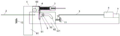
In order to realize the motion relationship among the particle push pin 3, the particle ejecting member 4 and the commutator 5, the feeding mechanism shown in fig. 6 needs two power sources, and meanwhile, the control sequences of the two power sources need to be matched, so that the cost is relatively high, and the control procedure is relatively complex. The present invention further provides a feeding mechanism requiring only one power source, and one embodiment is shown in fig. 14, the second rack 62 is further connected to the tail stopper 9, one end of an elastic element 10 is abutted to a fixed end 11, and the other end is abutted to the tail stopper 9; the push needle 3 of the particle implantation device is connected with a power source 8, the elastic element 10, the tail stopper 9 and the power source 8 are sequentially distributed along the axial direction of the puncture needle 2, and the power source 8 is closest to the puncture needle 3; the particle implantation device is also provided with a limiting part 12, the limiting part 12 is positioned between the second rack 62 and the fixed end 11, when the tail blocking part 9 is positioned between the limiting part 12 and the fixed end 11, the tail blocking part 9 is tightly attached to the power source 8 of the tail blocking part 9 under the thrust action of the elastic element 10, and when the tail blocking part 9 is contacted with the limiting part 12 and is limited by the limiting part 12 to move continuously, the tail blocking part 9 is separated from the power source 8. The elastic element 10 may be embodied as a spring. It can be seen that the tail stopper 9 is used for cooperating with the particle push pin 3 and limiting the movement range of the second rack 62, so that the movement relationship among the particle push pin 3, the particle ejecting member 4 and the commutator 5 can be realized by one power source. Here, the driving force acts on the tail stopper 9, and the tail stopper 9 drives the second rack 62 to move, so that the connection between the second rack 62 and the tail stopper 9 should be rigid.
Fig. 15-16 illustrate one cycle of particle feeding by the particle feeding mechanism of fig. 14. In A, the particle push pin 3 is connected with a power source 7, the dotted line circle shows that the power source 7 is directly contacted with the tail stopper 9, and the tail stopper 9 is kept to be tightly attached to the power source 7 under the action of a spring 10. The particle push pin 3 moves leftwards under the driving of the power source 7, namely action a, and the second rack 62 also moves leftwards synchronously under the action of the spring 10, namely action B in B; at this time, the second rack 62 is engaged with the gear 63, the rotating gear 63 drives the first rack 61 to move upwards, action c is generated, in the front stage of action b, because the sliding pin 52 of the commutator 5 is in the static section of the sliding groove 621 of the second rack 62, the commutator 5 does not rotate at this time, the particle top piece 4 is convenient to exit from the commutator 5, after the particle top piece 4 exits from the commutator 5, action b continues to develop, at this time, the sliding pin 52 of the commutator 5 enters the dynamic section of the sliding groove 621 of the second rack 62, and the commutator 5 starts to rotate, which is action d.
After the particle top 4 exits the particle trap 1, new particles are pushed into the first particle channel 106 of the particle trap 1 by the particle driving part 103, ready for the next particle feed.
In the step C, the particle push pin 3 continues to perform the action a, the second rack 62 performs the action b under the action of the spring 10, until the mechanical limit at the dotted circle in the step C limits the continuous movement of the tail stopper 9, the action b stops, and the second rack 62, the first rack 61 and the commutator 5 all stop moving. The second particle channel 51 of the diverter 5 is now seen in a horizontal position, completing the rotation of the particles from vertical to horizontal.
When the second rack 62 is stopped by mechanical limit, the particle push pin 3 continues to perform action a under the driving of the power source 7, at this time, the power source 7 is separated from the tail stopper 9, the particle push pin 3 which continues to move leftwards enters the diverter 5 to push particles out of the second particle channel 51 of the diverter 5 into the puncture needle 2, as shown in D, the front end of the puncture needle 2 is the pushed particles, and action a is terminated after the particles are completely pushed out of the puncture needle 2.
When a particle is pushed out, the particle push pin 3 moves to the right, and the action E is performed, as shown in E, and the process from E to H can be roughly understood as the reverse process of the action from a to D.
During the execution of action e, the particle push pin 3 will contact the tail stopper 9, as shown by F. And continuing to execute the action e, the particle push pin 3 pushes the second rack 62 to move rightwards, namely, the movement f, the movement of the second rack 62 simultaneously drives the gear 63 and the first rack 61 to generate the movement g, and simultaneously, because the sliding pin 52 is still in the dynamic section of the sliding groove 621 of the second rack 62, the commutator 5 also generates the rotary movement h at the moment, along with the continuation of the movement e, the commutator 5 rotates by 90 degrees from the horizontal state to the vertical state, then the sliding pin 52 enters the static section of the sliding groove 621, the movement of the commutator 5 is stopped, and the action h is ended. Meanwhile, the movement g of the first rack 61 is continued, the first rack 61 drives the particle ejecting member 4 to push the particles in the particle cartridge holder 1 into the commutator 5 again, and primary particle feeding is completed, as shown in H, at this time, the state of H is consistent with that of a, and a cycle period is completed.
Another embodiment of the feeding mechanism requiring only one power source is shown in fig. 17, and the difference between this embodiment and the embodiment of fig. 14 is the position of the position restricting member 12. In this embodiment, the position-limiting component 12 and the tail stopper 9 are located at two sides of the second rack 62 along the axial direction of the puncture needle 2, the connection between the second rack 62 and the tail stopper 9 should also be rigid, under the thrust action of the elastic element 10, initially, the tail stopper 9 is closely attached to the power source 8, the second rack 62 and the tail stopper 9 move leftward along with the power source 8 until the second rack 62 contacts the position-limiting component 12 and is limited by the position-limiting component 12 to move continuously, the tail stopper 9 is separated from the power source 8, and the power source 8 continues to push the push needle 3 leftward to move. The other movement principles are consistent with those of the feeding mechanism in fig. 14 and are not described in detail.
A further embodiment of the feeding mechanism requiring only one power source is shown in fig. 18, which differs from the embodiment of fig. 14 in the position of the elastic element 10. In this embodiment, one end of the elastic element 10 abuts against one fixed end 11, and the other end abuts against the connecting piece of the second rack 62; the tail stopper 9 and the power source 8 are sequentially distributed along the axial direction of the puncture needle 2, and the power source 8 is closer to the puncture needle 2; the limiting part 12 is positioned between the second rack 62 and the tail stopper 9; under the thrust action of the elastic element 10, initially, the tail stopper 9 is tightly attached to the power source 8, the second rack 62 and the tail stopper 9 move leftward along with the power source 8 until the tail stopper 9 contacts the limiting component 12 and is limited by the limiting component 12 to continue moving, the tail stopper 9 is separated from the power source 8, and the power source 8 continues to push the push pin 3 leftward to move. The other movement principles are consistent with those of the feeding mechanism in fig. 14 and are not described in detail. Here, the connection between the second rack 62 and the tail stopper 9 is not limited to be rigid connection or flexible connection, and when the connection between the second rack 62 and the tail stopper 9 is flexible connection, the flexible connection between the second rack 62 and the tail stopper 9 is kept in a tensioned state under the action of the elastic element 10, and the consistency of the movement of the second rack 62 and the tail stopper 9 can also be ensured. Further, the elastic member 10 is not limited to be in contact with the connection part of the second rack 62, and the elastic member 10 may be in direct contact with the second rack 62, as shown in fig. 19.
Fig. 20 is a further embodiment of the feeding mechanism requiring only one power source, which is different from the embodiment in fig. 19 in the position of the position-limiting component 12, in this embodiment, the position-limiting component 12 and the tail stopper 9 are located at two sides of the second rack 62 along the axial direction of the puncture needle 2, and since no position-limiting component is provided between the second rack 62 and the tail stopper 9, if the connection between the second rack 62 and the tail stopper 9 is flexible, the tail stopper 9 may move excessively under the action of gravity to make the flexible connection between the two in a loose state, causing undesirable phenomena such as winding other components, and therefore, the connection between the second rack 62 and the tail stopper 9 is rigid. Under the thrust action of the elastic element 10, initially, the tail stopper 9 is tightly attached to the power source 8, the second rack 62 and the tail stopper 9 move leftward along with the power source 8 until the second rack 62 contacts the limiting component 12 and is limited by the limiting component 12 to continue moving, the tail stopper 9 is separated from the power source 8, and the power source 8 continues to push the push pin 3 leftward to move.
Fig. 21 is a further embodiment of the feeding mechanism requiring only one power source, which differs from the embodiment of fig. 19 in the way in which the elastic element 10 acts on the second rack 62, in which case the elastic element 10 acts on the second rack 62 or on the connection of the second rack 62. Specifically, one end of the elastic element 10 is fixedly connected with a fixed end 11, and the other end is fixedly connected with the second rack 62 or the connecting piece of the second rack 62; the tail stopper 9 and the power source 8 are sequentially distributed along the axial direction of the puncture needle 2, and the power source 8 is closer to the puncture needle 2; the limiting part 12 is positioned between the second rack 62 and the tail stopper 9; under the action of the tensile force of the elastic element 10, initially, the tail stopper 9 is tightly attached to the power source 8, the second rack 62 and the tail stopper 9 move leftward along with the power source 8 until the tail stopper 9 contacts the limiting component 12 and is limited by the limiting component 12 to continue moving, the tail stopper 9 is separated from the power source 8, and the power source 8 continues to push the push pin 3 leftward to move. Here, the connection between the second rack 62 and the tail stopper 9 is not limited to a rigid connection or a flexible connection.
Fig. 22 shows a further embodiment of the feeding mechanism requiring only one power source, which differs from the embodiment of fig. 21 in the position of the position-limiting member 12, in which the position-limiting member 12 and the trailing stop 9 are located on both sides of the second rack 62 in the axial direction of the puncture needle 2, and since no position-limiting member is provided between the second rack 62 and the trailing stop 9, the connection between the second rack 62 and the trailing stop 9 is rigid. Under the action of the tensile force of the elastic element 10, initially, the tail stopper 9 is tightly attached to the power source 8, the second rack 62 and the tail stopper 9 move leftwards along with the power source 8 until the second rack 62 contacts the limiting component 12 and is limited by the limiting component 12 to move continuously, the tail stopper 9 is separated from the power source 8, and the power source 8 continues to push the push pin 3 leftwards to move.
Fig. 23 is a further embodiment of a feeding mechanism requiring only one power source, which differs from the embodiment of fig. 14 in the way the elastic element 10 acts on the tail stop 9, in which case the elastic element 10 exerts a pulling force on the tail stop 9. Specifically, the second rack 62 is rigidly connected to the tail stopper 9, one end of the elastic element 10 is fixedly connected to a fixed end 11, the other end is fixedly connected to the tail stopper 9, the tail stopper 9 and the power source 8 are sequentially distributed along the axial direction of the puncture needle, and the power source 8 is closer to the puncture needle; the limiting component 12 is located between the second rack 62 and the tail stopper 9, under the pulling force of the elastic element 10, initially, the tail stopper 9 is tightly attached to the power source 8, the second rack 62 and the tail stopper 9 move leftward along with the power source 8 until the tail stopper 9 contacts the limiting component 12 and is limited by the limiting component 12 to continue moving, the tail stopper 9 is separated from the power source 8, and the power source 8 continues to push the push pin 3 leftward to move.
Fig. 24 shows a further embodiment of the feeding mechanism requiring only one power source, which differs from the embodiment of fig. 23 in the position of the position-limiting member 12, in which the position-limiting member 12 and the trailing stop 9 are located on both sides of the second rack 62 in the axial direction of the puncture needle 2, and the connection between the second rack 62 and the trailing stop 9 is rigid. Under the action of the tensile force of the elastic element 10, initially, the tail stopper 9 is tightly attached to the power source 8, the second rack 62 and the tail stopper 9 move leftwards along with the power source 8 until the second rack 62 contacts the limiting component 12 and is limited by the limiting component 12 to move continuously, the tail stopper 9 is separated from the power source 8, and the power source 8 continues to push the push pin 3 leftwards to move.
In fact, a redundant design may be implemented to enhance stability, for example, a thrust elastic element may be provided for the tail stopper 9 and the second rack 62, respectively, or a thrust elastic element may be provided for the tail stopper 9 and a tension elastic element may be provided for the second rack 62. The position-limiting means 12 can be arranged between the second rack 62 and the tail catch 9, on both sides of the second rack 62 with the tail catch 9, or both, as required, which are conventional variations that can be made by those skilled in the art.
The above specific structure that only one power source is needed is designed for the feeding mechanism in which the length direction of the particle cassette is parallel to the axial direction of the puncture needle, and those skilled in the art will readily recognize that these specific embodiments are also applicable to other cases in which the length direction of the particle cassette is not perpendicular to the axial direction of the puncture needle, and will not be described again.
Thus, it should be appreciated by those skilled in the art that while a number of exemplary embodiments of the invention have been illustrated and described in detail herein, many other variations or modifications consistent with the principles of the invention may be directly determined or derived from the disclosure of the present invention without departing from the spirit and scope of the invention. Accordingly, the scope of the invention should be understood and interpreted to cover all such other variations or modifications.

Claims (10)

1. A feeding mechanism of a particle implantation device, wherein the particle implantation device comprises a push needle for pushing particles into a puncture needle; the feeding mechanism comprises a particle cartridge clip, and is characterized in that:
the particle cartridge comprises a particle shield cylinder, a particle storage cavity and a particle driving part, wherein the particle storage cavity is positioned in the particle shield cylinder and comprises a first end and a second end opposite to the first end, and the particle driving part pushes particles from the first end to the second end; said particle magazine having a first particle passageway at said second end, said feeder mechanism including a particle tip movable in said first particle passageway; the length direction of the particle clip is arranged in a non-perpendicular state with the axial direction of the puncture needle;
the feeding mechanism further comprises a commutator, and a second particle channel is arranged in the commutator; the commutator is provided with a first working position and a second working position, when the commutator is positioned at the first working position, the first particle channel is coaxial with the second particle channel, and the particle ejecting piece ejects particles in the first particle channel into the second particle channel; when the commutator is located at the second working position, the second particle channel is coaxial with the push needle and the puncture needle, and the push needle pushes the particles in the second particle channel into the puncture needle.
2. The feed mechanism of claim 1, wherein: the length direction of the particle clip is parallel to the axial direction of the puncture needle, and the axial direction of the particle ejecting piece is perpendicular to the axial direction of the puncture needle.
3. The feed mechanism of claim 1 or 2, wherein: a sliding pin is arranged on the commutator; the feeding mechanism further comprises a moving assembly, and the moving assembly comprises a first rack, a second rack and a gear;
the first rack is provided with teeth meshed with the gear, and the first rack is connected with the particle ejecting piece and drives the particle ejecting piece to move;
the second rack is provided with a sliding groove and teeth meshed with the gear, the sliding groove is matched with a sliding pin of the commutator, the sliding groove is divided into two continuous sections, one section is a static section, the commutator is in a static state when the sliding pin of the commutator slides, the other section is a dynamic section, and the sliding pin of the commutator generates deviation after entering the static section to drive the commutator to rotate; the static section of the sliding groove is closer to the puncture needle than the dynamic section.
4. The feed mechanism of claim 3, wherein: one of the first rack and the second rack is driven by a power source.
5. The feed mechanism of claim 3, wherein: the second rack is connected with a tail stopper, a push pin of the particle implantation device is connected with a power source, the tail stopper is tightly attached to the power source within the stroke range of the second rack under the action of an elastic element, and the second rack and the tail stopper synchronously move along with the power source; and when the power source continues to drive the push needle to move towards the puncture needle outside the stroke range of the second rack, the tail stopper is separated from the power source.
6. The feed mechanism of claim 5, wherein: the second rack is rigidly connected with the tail stopper, the elastic element comprises a first elastic element, one end of the first elastic element is abutted with a fixed end, and the other end of the first elastic element is abutted with the tail stopper; the first elastic element, the tail stopper and the power source are sequentially distributed along the axial direction of the puncture needle, and the power source is closest to the puncture needle;
the particle implantation device is also provided with a limiting component, the limiting component is positioned between the second rack and the fixed end, when the tail stopper is positioned between the limiting component and the fixed end, the tail stopper is tightly attached to the power source under the thrust action of the first elastic element, and when the tail stopper is contacted with the limiting component and is limited by the limiting component to move continuously, the tail stopper is separated from the power source;
or,
the particle implantation device is also provided with a limiting component, and the limiting component and the tail stopper are positioned at two sides of the second rack along the axial direction of the puncture needle; under the thrust action of the first elastic element, the tail stopper is tightly attached to the power source within the stroke range of the second rack, and when the second rack is contacted with the limiting component and is limited by the limiting component to move continuously, the tail stopper is separated from the power source.
7. The feed mechanism of claim 5, wherein: the elastic element comprises a first elastic element, one end of the first elastic element is abutted with a fixed end, and the other end of the first elastic element is abutted with the second rack or the connecting piece of the second rack; the tail stopper and the power source are sequentially distributed along the axial direction of the puncture needle, and the power source is closer to the puncture needle; the particle implantation device is also provided with a limiting component, and the limiting component is positioned between the second rack and the tail stopper; under the thrust action of the first elastic element, within the stroke range of the second rack, the tail stopper is tightly attached to the power source, and when the tail stopper is contacted with the limiting component and is limited by the limiting component to move continuously, the tail stopper is separated from the power source.
8. The feed mechanism of claim 5, wherein: the second rack is in rigid connection with the tail stopper;
the elastic element comprises a first elastic element, one end of the first elastic element is abutted with a fixed end, and the other end of the first elastic element is abutted with the second rack or the connecting piece of the second rack; the tail stopper and the power source are sequentially distributed along the axial direction of the puncture needle, and the power source is closer to the puncture needle; the particle implantation device is also provided with a limiting component, and the limiting component and the tail stopper are positioned at two sides of the second rack along the axial direction of the puncture needle; under the thrust action of the first elastic element, the tail stopper is tightly attached to the power source within the stroke range of the second rack, and when the second rack is contacted with the limiting component and is limited by the limiting component to move continuously, the tail stopper is separated from the power source;
or,
the elastic element comprises a first elastic element, one end of the first elastic element is fixedly connected with one fixed end, and the other end of the first elastic element is fixedly connected with the second rack or the connecting piece of the second rack; the tail stopper and the power source are sequentially distributed along the axial direction of the puncture needle, and the power source is closer to the puncture needle; the particle implantation device is also provided with a limiting component, and the limiting component and the tail stopper are positioned at two sides of the second rack along the axial direction of the puncture needle; under the action of the tensile force of the first elastic element, the tail stopper is tightly attached to the power source within the stroke range of the second rack, and when the second rack is contacted with the limiting component and is limited by the limiting component to move continuously, the tail stopper is separated from the power source.
9. The feed mechanism of claim 5, wherein: the elastic element comprises a first elastic element, one end of the first elastic element is fixedly connected with one fixed end, and the other end of the first elastic element is fixedly connected with the second rack or the connecting piece of the second rack; the tail stopper and the power source are sequentially distributed along the axial direction of the puncture needle, and the power source is closer to the puncture needle; the particle implantation device is also provided with a limiting component, and the limiting component is positioned between the second rack and the tail stopper; under the action of the tensile force of the first elastic element, within the travel range of the second rack, the tail stopper is tightly attached to the power source, and when the tail stopper is contacted with the limiting component and is limited by the limiting component to move continuously, the tail stopper is separated from the power source.
10. The feed mechanism of claim 5, wherein: the second rack is rigidly connected with the tail stopper, the elastic element comprises a first elastic element, one end of the first elastic element is fixedly connected with one fixed end, and the other end of the first elastic element is fixedly connected with the tail stopper; the tail stopper and the power source are sequentially distributed along the axial direction of the puncture needle, and the power source is closer to the puncture needle;
the particle implantation device is also provided with a limiting component, and the limiting component is positioned between the second rack and the tail stopper; under the action of the tensile force of the first elastic element, within the stroke range of the second rack, the tail stopper is tightly attached to the power source, and when the tail stopper is contacted with the limiting component and is limited by the limiting component to move continuously, the tail stopper is separated from the power source;
or,
the particle implantation device is also provided with a limiting component, and the limiting component and the tail stopper are positioned at two sides of the second rack along the axial direction of the puncture needle; under the action of the tensile force of the first elastic element, the tail stopper is tightly attached to the power source within the stroke range of the second rack, and when the second rack is contacted with the limiting component and is limited by the limiting component to move continuously, the tail stopper is separated from the power source.
CN201910823304.0A 2019-09-02 2019-09-02 Feeding mechanism of particle implantation device Active CN110464979B (en)

Priority Applications (1)

Application Number Priority Date Filing Date Title
CN201910823304.0A CN110464979B (en) 2019-09-02 2019-09-02 Feeding mechanism of particle implantation device

Applications Claiming Priority (1)

Application Number Priority Date Filing Date Title
CN201910823304.0A CN110464979B (en) 2019-09-02 2019-09-02 Feeding mechanism of particle implantation device

Publications (2)

Publication Number Publication Date
CN110464979A CN110464979A (en) 2019-11-19
CN110464979B true CN110464979B (en) 2021-05-07

Family

ID=68514714

Family Applications (1)

Application Number Title Priority Date Filing Date
CN201910823304.0A Active CN110464979B (en) 2019-09-02 2019-09-02 Feeding mechanism of particle implantation device

Country Status (1)

Country Link
CN (1) CN110464979B (en)

Families Citing this family (1)

* Cited by examiner, † Cited by third party
Publication number Priority date Publication date Assignee Title
CN119658395B (en) * 2025-02-21 2025-05-09 成都中核高通同位素股份有限公司 An automated production system for iridium components

Citations (3)

* Cited by examiner, † Cited by third party
Publication number Priority date Publication date Assignee Title
CN202010370U (en) * 2011-03-04 2011-10-19 上海欣科医药有限公司 Radioactive particle implantation apparatus
CN102657548A (en) * 2012-04-25 2012-09-12 天津大学 Reversing nuclear magnetic compatible puncture needle clamp
CN104162226A (en) * 2014-07-10 2014-11-26 北京理工大学 Automation device capable of implanting radioactive particles continuously

Family Cites Families (3)

* Cited by examiner, † Cited by third party
Publication number Priority date Publication date Assignee Title
US20050075529A1 (en) * 2003-10-03 2005-04-07 Laust Pedersen Brachytherapy applicator chuck
US20130035537A1 (en) * 2011-08-05 2013-02-07 Wallace Daniel T Robotic systems and methods for treating tissue
US9403033B1 (en) * 2015-04-24 2016-08-02 Gammatile Llc Apparatus and method for loading radioactive seeds into carriers

Patent Citations (3)

* Cited by examiner, † Cited by third party
Publication number Priority date Publication date Assignee Title
CN202010370U (en) * 2011-03-04 2011-10-19 上海欣科医药有限公司 Radioactive particle implantation apparatus
CN102657548A (en) * 2012-04-25 2012-09-12 天津大学 Reversing nuclear magnetic compatible puncture needle clamp
CN104162226A (en) * 2014-07-10 2014-11-26 北京理工大学 Automation device capable of implanting radioactive particles continuously

Also Published As

Publication number Publication date
CN110464979A (en) 2019-11-19

Similar Documents

Publication Publication Date Title
CN111281498B (en) Automatic particle implanter
US20180070948A1 (en) Surgical clip applier
CN212234612U (en) Automatic particle implantation device
US5333772A (en) Multiple fire endoscopic stapling mechanism
EP1405595B2 (en) Piercing device
US7621926B2 (en) Multi-fire surgical clip applier
US9445761B2 (en) Lancet ejection and advancement mechanism for multi-lancet cartridge
CN110464979B (en) Feeding mechanism of particle implantation device
JP2017521176A (en) Cannula insertion system, method and apparatus
CN113081145A (en) Simple tissue clip repeating clip applier
CN109675184A (en) A kind of particle implantation device
CN114699658B (en) A multi-particle implantation end effector for continuous puncture
US20240122607A1 (en) Clip applying mechanism and clip applying apparatus thereof
US20240122603A1 (en) Clip applying mechanism and clip applying apparatus thereof
US20240122606A1 (en) Clip applying mechanism and clip applying apparatus thereof
US20240122605A1 (en) Clip applying mechanism and clip applying apparatus thereof
KR20220087528A (en) Drive Assemblies for Drug Delivery Devices
CN212369165U (en) a retinal syringe
CN117064514A (en) Conveying system and medical instrument
EP4356851A1 (en) Clip applying mechanism and clip applying apparatus thereof
CN222765576U (en) Radioactive source feeding device
CN219423050U (en) Intraocular implant implantation device
CN219184490U (en) Intraocular implant implantation device
CN221692019U (en) Acupuncture needle silo for continuously firing acupuncture gun
CN114681718B (en) Multiple quantitative injector

Legal Events

Date Code Title Description
PB01 Publication
PB01 Publication
SE01 Entry into force of request for substantive examination
GR01 Patent grant
GR01 Patent grant
CP03 Change of name, title or address

Address after: Room 101, building 13, No.158, Jinfeng Road, science and Technology City, Suzhou, Jiangsu 215000

Patentee after: Jiangsu University of technology collaborative medical robot Co.,Ltd.

Address before: 215000 101, building 13, No.158, Jinfeng Road, science and Technology City, Suzhou, Jiangsu Province

Patentee before: JIANGSU GONGDA BOSHI MEDICAL ROBOT RESEARCH DEVELOPMENT Co.,Ltd.

CP03 Change of name, title or address
TR01 Transfer of patent right

Effective date of registration: 20220413

Address after: Room 102-4, building 13, No. 158, Jinfeng Road, science and Technology City, high tech Zone, Suzhou, Jiangsu 215000

Patentee after: Suzhou Naiwei Medical Technology Co.,Ltd.

Address before: Room 101, building 13, No.158, Jinfeng Road, science and Technology City, Suzhou, Jiangsu 215000

Patentee before: Jiangsu University of technology collaborative medical robot Co.,Ltd.

TR01 Transfer of patent right