CN110418411B - DMRS indication method, device and network device - Google Patents
DMRS indication method, device and network device Download PDFInfo
- Publication number
- CN110418411B CN110418411B CN201810395058.9A CN201810395058A CN110418411B CN 110418411 B CN110418411 B CN 110418411B CN 201810395058 A CN201810395058 A CN 201810395058A CN 110418411 B CN110418411 B CN 110418411B
- Authority
- CN
- China
- Prior art keywords
- dmrs
- target
- ofdm symbol
- ofdm
- obtaining
- Prior art date
- Legal status (The legal status is an assumption and is not a legal conclusion. Google has not performed a legal analysis and makes no representation as to the accuracy of the status listed.)
- Active
Links
Images


Classifications
-
- H—ELECTRICITY
- H04—ELECTRIC COMMUNICATION TECHNIQUE
- H04L—TRANSMISSION OF DIGITAL INFORMATION, e.g. TELEGRAPHIC COMMUNICATION
- H04L5/00—Arrangements affording multiple use of the transmission path
- H04L5/0001—Arrangements for dividing the transmission path
- H04L5/0003—Two-dimensional division
- H04L5/0005—Time-frequency
- H04L5/0007—Time-frequency the frequencies being orthogonal, e.g. OFDM(A) or DMT
-
- H—ELECTRICITY
- H04—ELECTRIC COMMUNICATION TECHNIQUE
- H04L—TRANSMISSION OF DIGITAL INFORMATION, e.g. TELEGRAPHIC COMMUNICATION
- H04L5/00—Arrangements affording multiple use of the transmission path
- H04L5/003—Arrangements for allocating sub-channels of the transmission path
- H04L5/0048—Allocation of pilot signals, i.e. of signals known to the receiver
-
- H—ELECTRICITY
- H04—ELECTRIC COMMUNICATION TECHNIQUE
- H04W—WIRELESS COMMUNICATION NETWORKS
- H04W72/00—Local resource management
- H04W72/20—Control channels or signalling for resource management
- H04W72/23—Control channels or signalling for resource management in the downlink direction of a wireless link, i.e. towards a terminal
Landscapes
- Engineering & Computer Science (AREA)
- Signal Processing (AREA)
- Computer Networks & Wireless Communication (AREA)
- Mobile Radio Communication Systems (AREA)
Abstract
本发明提供一种DMRS的指示方法、装置及网络设备,涉及通信领域,以解决DMRS数量无法满足日益增加的用户终端的数量的问题而发明。该方法包括:获取目标DMRS pattern对应的目标DMRS端口指示表,其中,所述目标DMRS pattern根据目标正交频分复用OFDM符号位和OCC获得,所述目标OFDM符号位由第一OFDM符号位和第二OFDM符号位组成,第一OFDM符号位为原DMRS使用的原OFDM符号位,第二OFDM符号位的个数是第一OFDM符号位的整数倍;根据所述目标DMRS端口指示表,向用户终端发送DMRS指示信息,以使得所述用户终端根据所述DMRS指示信息传输数据。本发明可以应用在NOMA技术中。

The present invention provides a DMRS indication method, device and network equipment, which relate to the field of communication and are invented to solve the problem that the number of DMRS cannot meet the increasing number of user terminals. The method includes: obtaining a target DMRS port indication table corresponding to a target DMRS pattern, wherein the target DMRS pattern is obtained according to a target OFDM symbol bit and OCC, and the target OFDM symbol bit is obtained from the first OFDM symbol bit and the second OFDM symbol bits, the first OFDM symbol bits are the original OFDM symbol bits used by the original DMRS, and the number of the second OFDM symbol bits is an integer multiple of the first OFDM symbol bits; according to the target DMRS port indication table, The DMRS indication information is sent to the user terminal, so that the user terminal transmits data according to the DMRS indication information. The present invention can be applied in NOMA technology.
Description
技术领域technical field
本发明涉及通信技术领域,尤其涉及一种DMRS的指示方法、装置及网络设备。The present invention relates to the field of communication technologies, and in particular, to a DMRS indication method, device and network equipment.
背景技术Background technique
在5G网络中,为了提高传输速度,降低用户延迟,可以采用非正交多址接入(Non-orthogonal Multiple Access,NOMA)技术传输数据。具体地,基站为用户终端(UserEquipment,UE)从预先设置的传输资源池中分配可以使用的传输资源,UE使用该传输资源进行数据传输。然而,由于NOMA技术本身的非正交性,多个UE同时传输数据时,可能会有干扰和冲突出现。In the 5G network, in order to increase the transmission speed and reduce the user delay, the Non-orthogonal Multiple Access (NOMA) technology can be used to transmit data. Specifically, the base station allocates available transmission resources for a user terminal (User Equipment, UE) from a preset transmission resource pool, and the UE uses the transmission resources for data transmission. However, due to the non-orthogonal nature of NOMA technology, interference and collision may occur when multiple UEs transmit data simultaneously.
为了解决上述问题,在现有技术中,基站为各个UE分配相互正交的解调参考信号(Demodulation Reference Signal,DMRS),UE根据该DMRS获取传输资源,进行数据传输。In order to solve the above problem, in the prior art, the base station allocates mutually orthogonal demodulation reference signals (Demodulation Reference Signal, DMRS) to each UE, and the UE obtains transmission resources according to the DMRS and performs data transmission.
现有技术为每个UE分配一个唯一的DMRS,然而,随着网络技术的不断发展,UE的数量日趋增加,如何扩展DMRS的数量以满足在使用NOMA技术时,大量UE可以使用相同的时频资源传输数据,成为亟待解决的问题。The existing technology allocates a unique DMRS to each UE. However, with the continuous development of network technology, the number of UEs increases day by day. How to expand the number of DMRSs to meet the requirement that a large number of UEs can use the same time-frequency when using NOMA technology. The resource transmission data has become an urgent problem to be solved.
发明内容SUMMARY OF THE INVENTION
本发明实施例提供一种DMRS的指示方法、装置及网络设备,以解决现有 DMRS数量无法满足日益增加的用户终端的数量的问题。Embodiments of the present invention provide a DMRS indication method, apparatus, and network equipment, so as to solve the problem that the number of existing DMRSs cannot meet the increasing number of user terminals.
为了解决上述技术问题,本发明是这样实现的:In order to solve the above-mentioned technical problems, the present invention is achieved in this way:
第一方面,本发明实施例提供了一种DMRS的指示方法,包括:获取目标 DMRSpattern对应的目标DMRS端口指示表,其中,所述目标DMRS pattern根据目标正交频分复用OFDM符号位和正交掩码OCC获得,所述目标OFDM符号位由第一OFDM符号位和第二OFDM符号位组成,所述第一OFDM符号位为原DMRS使用的原OFDM符号位,所述第二OFDM符号位的个数是所述第一 OFDM符号位的整数倍;根据所述目标DMRS端口指示表,向用户终端发送 DMRS指示信息,以使得所述用户终端根据所述DMRS指示信息传输数据。In a first aspect, an embodiment of the present invention provides a DMRS indication method, including: obtaining a target DMRS port indication table corresponding to a target DMRS pattern, wherein the target DMRS pattern is based on the target OFDM symbol bits and positive OFDM symbols. The cross-mask OCC is obtained, the target OFDM symbol bit is composed of a first OFDM symbol bit and a second OFDM symbol bit, the first OFDM symbol bit is the original OFDM symbol bit used by the original DMRS, and the second OFDM symbol bit is The number of is an integer multiple of the first OFDM symbol bits; according to the target DMRS port indication table, DMRS indication information is sent to the user terminal, so that the user terminal transmits data according to the DMRS indication information.
第二方面,本发明实施例还提供一种DMRS的指示装置,包括:In a second aspect, an embodiment of the present invention further provides a DMRS indication device, including:
第一获取模块,用于获取目标DMRS pattern对应的目标DMRS端口指示表,其中,所述目标DMRS pattern由第二获取模块根据目标正交频分复用OFDM符号位和正交掩码OCC获得,所述目标OFDM符号位由第一OFDM符号位和第二OFDM符号位组成,所述第一OFDM符号位为原DMRS使用的原OFDM符号位,所述第二OFDM符号位的个数是所述第一OFDM符号位的整数倍;;a first obtaining module, configured to obtain a target DMRS port indication table corresponding to a target DMRS pattern, wherein the target DMRS pattern is obtained by the second obtaining module according to the target orthogonal frequency division multiplexing OFDM symbol bits and the orthogonal mask OCC, The target OFDM symbol bits are composed of first OFDM symbol bits and second OFDM symbol bits, the first OFDM symbol bits are the original OFDM symbol bits used by the original DMRS, and the number of the second OFDM symbol bits is the an integer multiple of the first OFDM symbol bits;
发送模块,用于根据所述第一获取模块获取的目标DMRS端口指示表,向用户终端发送DMRS指示信息,以使得所述用户终端根据所述DMRS指示信息传输数据。A sending module, configured to send DMRS indication information to the user terminal according to the target DMRS port indication table obtained by the first obtaining module, so that the user terminal transmits data according to the DMRS indication information.
第三方面,本发明实施例还提供一种网络设备,包括:存储器、处理器及存储在所述存储器上并可在所述处理器上运行的计算机程序,所述计算机程序被所述处理器执行时实现如前述的DMRS的指示方法的步骤。In a third aspect, an embodiment of the present invention further provides a network device, including: a memory, a processor, and a computer program stored on the memory and executable on the processor, the computer program being executed by the processor When executed, the steps of the aforementioned DMRS indication method are implemented.
第四方面,本发明实施例还提供一种计算机可读存储介质,包括:所述计算机可读存储介质上存储有计算机程序,所述计算机程序被处理器执行时实现如前述的DMRS的指示方法中的步骤。In a fourth aspect, an embodiment of the present invention further provides a computer-readable storage medium, comprising: a computer program is stored on the computer-readable storage medium, and when the computer program is executed by a processor, the aforementioned DMRS indication method is implemented steps in .
本发明实施例提供的技术方案,目标OFDM符号位相较于原DMRS使用的原OFDM符号位的个数增加了,使得根据目标OFDM符号位以及预先设置的正交掩码OCC生成的目标DMRSpattern个数也增加了,进而增加了目标DMRS 端口的数量,解决了现有技术DMRS数量无法满足日益增加的用户终端的数量的问题。由于DMRS数量增加了,降低了用户终端采用NOMA技术传输数据的干扰和冲突。According to the technical solution provided by the embodiment of the present invention, the number of target OFDM symbol bits is increased compared with the number of original OFDM symbol bits used by the original DMRS, so that the number of target DMRSpatterns generated according to the target OFDM symbol bits and the preset orthogonal mask OCC The number of target DMRS ports is also increased, thereby increasing the number of target DMRS ports, which solves the problem that the number of DMRSs in the prior art cannot meet the increasing number of user terminals. Since the number of DMRSs increases, the interference and collision of data transmitted by the user terminal using the NOMA technology are reduced.
附图说明Description of drawings
为了更清楚地说明本发明实施例的技术方案,下面将对本发明实施例描述中所需要使用的附图作简单地介绍,显而易见地,下面描述中的附图仅仅是本发明的一些实施例,对于本领域普通技术人员来讲,在不付出创造性劳动性的前提下,还可以根据这些附图获得其他的附图。In order to illustrate the technical solutions of the embodiments of the present invention more clearly, the following briefly introduces the accompanying drawings that need to be used in the description of the embodiments of the present invention. Obviously, the drawings in the following description are only some embodiments of the present invention. For those of ordinary skill in the art, other drawings can also be obtained from these drawings without creative labor.
图1是本发明实施例提供的DMRS的指示方法的流程图;1 is a flowchart of a method for indicating a DMRS provided by an embodiment of the present invention;
图2是图1所示的本发明实施例提供的DMRS的指示方法中获得目标DMRS pattern的方法的流程图一;2 is a flowchart 1 of a method for obtaining a target DMRS pattern in the DMRS indication method provided by the embodiment of the present invention shown in FIG. 1;
图3是本发明实施例提供的DMRS的指示方法中场景一下的目标OFDM符号位的示意图;3 is a schematic diagram of target OFDM symbol bits in the first scenario in the DMRS indication method provided by an embodiment of the present invention;
图4是本发明实施例提供的DMRS的指示方法中场景一下UE0和UE1的 DMRSpattern示意图;4 is a schematic diagram of the DMR pattern of UE0 and UE1 in the first scene in the DMRS indication method provided by the embodiment of the present invention;
图5是本发明实施例提供的DMRS的指示方法中场景一下UE2和UE3的 DMRSpattern示意图;5 is a schematic diagram of a DMRS pattern of UE2 and UE3 in the first scenario of the DMRS indication method provided by the embodiment of the present invention;
图6是本发明实施例提供的DMRS的指示方法中场景一下UE4和UE5的 DMRSpattern示意图;6 is a schematic diagram of a DMRS pattern of UE4 and UE5 in the first scenario of the DMRS indication method provided by the embodiment of the present invention;
图7是本发明实施例提供的DMRS的指示方法中场景一下UE6和UE7的 DMRSpattern示意图;FIG. 7 is a schematic diagram of the DMR pattern of UE6 and UE7 in the second scenario of the DMRS indication method provided by the embodiment of the present invention;
图8是图1所示的本发明实施例提供的DMRS的指示方法中获得目标DMRS pattern的方法的流程图二;8 is a second flowchart of a method for obtaining a target DMRS pattern in the DMRS indication method provided by the embodiment of the present invention shown in FIG. 1;
图9是本发明实施例提供的DMRS的指示方法中场景二下的目标OFDM符号位的示意图;9 is a schematic diagram of a target OFDM symbol bit under scenario two in a DMRS indication method provided by an embodiment of the present invention;
图10是本发明实施例提供的DMRS的指示方法中场景二下UE0-UE3的DMRS pattern示意图一;FIG. 10 is a schematic diagram 1 of a DMRS pattern of UE0-UE3 in scenario two in a DMRS indication method provided by an embodiment of the present invention;
图11是本发明实施例提供的DMRS的指示方法中场景二下UE4-UE7的 DMRSpattern示意图;11 is a schematic diagram of a DMR pattern of UE4-UE7 in scenario two in a DMRS indication method provided by an embodiment of the present invention;
图12是本发明实施例提供的DMRS的指示方法中场景二下UE8-UE11的 DMRSpattern示意图;12 is a schematic diagram of a DMR pattern of UE8-UE11 in scenario two in a DMRS indication method provided by an embodiment of the present invention;
图13是本发明实施例提供的DMRS的指示方法中场景二下UE12-UE15的 DMRSpattern示意图;13 is a schematic diagram of a DMR pattern of UE12-UE15 in scenario two in a DMRS indication method provided by an embodiment of the present invention;
图14是图1所示的本发明实施例提供的DMRS的指示方法中获得目标DMRS pattern的方法的流程图三;14 is a third flowchart of a method for obtaining a target DMRS pattern in the DMRS indication method provided by the embodiment of the present invention shown in FIG. 1;
图15是本发明实施例提供的DMRS的指示方法中场景三下UE0-UE3的 DMRSpattern示意图;15 is a schematic diagram of a DMR pattern of UE0-UE3 in scenario three in a DMRS indication method provided by an embodiment of the present invention;
图16是本发明实施例提供的DMRS的指示方法中场景三下UE4-UE7的 DMRSpattern示意图;16 is a schematic diagram of a DMR pattern of UE4-UE7 in scenario three in a DMRS indication method provided by an embodiment of the present invention;
图17是本发明实施例提供的DMRS的指示方法中场景三下UE8-UE11的 DMRSpattern示意图;17 is a schematic diagram of a DMR pattern of UE8-UE11 in scenario three in a DMRS indication method provided by an embodiment of the present invention;
图18是本发明实施例提供的DMRS的指示方法中场景三下UE12-UE15的 DMRSpattern示意图;18 is a schematic diagram of a DMR pattern of UE12-UE15 in scenario three in a DMRS indication method provided by an embodiment of the present invention;
图19是图1所示的本发明实施例提供的DMRS的指示方法中获得目标 DMRSpattern的方法的流程图四;Fig. 19 is the flow chart four of the method for obtaining target DMRSpattern in the indication method of DMRS provided by the embodiment of the present invention shown in Fig. 1;
图20是本发明实施例提供的DMRS的指示方法中场景四下UE0和UE1的 DMRSpattern示意图;Figure 20 is a schematic diagram of the DMR pattern of UE0 and UE1 under scenario four in the DMRS indication method provided by the embodiment of the present invention;
图21是本发明实施例提供的DMRS的指示方法中场景四下UE2和UE3的 DMRSpattern示意图;Figure 21 is a schematic diagram of the DMR pattern of UE2 and UE3 under scenario four in the DMRS indication method provided by the embodiment of the present invention;
图22是本发明实施例提供的DMRS的指示方法中场景四下UE4和UE5的 DMRSpattern示意图;Figure 22 is a schematic diagram of the DMR pattern of UE4 and UE5 under scenario four in the DMRS indication method provided by the embodiment of the present invention;
图23是本发明实施例提供的DMRS的指示方法中场景四下UE6和UE7的 DMRSpattern示意图;Figure 23 is a schematic diagram of the DMR pattern of UE6 and UE7 under scenario four in the DMRS indication method provided by the embodiment of the present invention;
图24是本发明实施例提供的DMRS的指示方法中场景四下UE8和UE9的 DMRSpattern示意图;24 is a schematic diagram of a DMR pattern of UE8 and UE9 under scenario four in the DMRS indication method provided by the embodiment of the present invention;
图25是本发明实施例提供的DMRS的指示方法中场景四下UE10和UE11 的DMRSpattern示意图;25 is a schematic diagram of a DMR pattern of UE10 and UE11 in scenario four in a DMRS indication method provided by an embodiment of the present invention;
图26是本发明实施例提供的DMRS的指示方法中场景二下UE0-UE3的 DMRSpattern示意图二;Figure 26 is a schematic diagram 2 of a DMR pattern of UE0-UE3 in a second scenario in a DMRS indication method provided by an embodiment of the present invention;
图27是本发明另一实施例提供的DMRS的指示方法的流程图;27 is a flowchart of a method for indicating a DMRS provided by another embodiment of the present invention;
图28是本发明另一实施例提供的DMRS的指示方法中原DMRSpattern示意图;28 is a schematic diagram of the original DMRPattern in the DMRS indication method provided by another embodiment of the present invention;
图29是本发明另一实施例提供的DMRS的指示方法中目标DMRSpattern示意图;29 is a schematic diagram of a target DMRSpattern in a DMRS indication method provided by another embodiment of the present invention;
图30是本发明实施例提供的DMRS的指示装置的结构示意图;30 is a schematic structural diagram of a DMRS indication device provided by an embodiment of the present invention;
图31是图30所示的本发明实施例提供的DMRS的指示装置中第二获取模块3002的结构示意图一;FIG. 31 is a first structural diagram of the
图32是图30所示的本发明实施例提供的DMRS的指示装置中第二获取模块3002的结构示意图二;FIG. 32 is a second structural diagram of the
图33是图30所示的本发明实施例提供的DMRS的指示装置中第二获取模块3002的结构示意图三;FIG. 33 is a third structural diagram of the
图34是图30所示的本发明实施例提供的DMRS的指示装置中第二获取模块3002的结构示意图四。FIG. 34 is a fourth schematic structural diagram of the
具体实施方式Detailed ways
下面将结合本发明实施例中的附图,对本发明实施例中的技术方案进行清楚、完整地描述,显然,所描述的实施例是本发明一部分实施例,而不是全部的实施例。基于本发明中的实施例,本领域普通技术人员在没有作出创造性劳动前提下所获得的所有其他实施例,都属于本发明保护的范围。The technical solutions in the embodiments of the present invention will be clearly and completely described below with reference to the accompanying drawings in the embodiments of the present invention. Obviously, the described embodiments are part of the embodiments of the present invention, but not all of the embodiments. Based on the embodiments of the present invention, all other embodiments obtained by those of ordinary skill in the art without creative efforts shall fall within the protection scope of the present invention.
如图1所示,本发明实施例提供的DMRS的指示方法,包括:As shown in FIG. 1, the DMRS indication method provided by the embodiment of the present invention includes:
步骤101、获取目标DMRS pattern对应的目标DMRS端口指示表,其中,目标DMRSpattern根据目标正交频分复用(Orthogonal Frequency Division Multiplexing,OFDM)符号位和正交覆盖码(Orthogonal Cover Code,OCC)获得,目标OFDM符号位由第一OFDM符号位和第二OFDM符号位组成,第一OFDM 符号位为原DMRS使用的原OFDM符号位,第二OFDM符号位的个数是第一 OFDM符号位的整数倍。Step 101: Obtain a target DMRS port indication table corresponding to the target DMRS pattern, wherein the target DMRS pattern is obtained according to the target orthogonal frequency division multiplexing (Orthogonal Frequency Division Multiplexing, OFDM) symbol bits and an orthogonal cover code (Orthogonal Cover Code, OCC) , the target OFDM symbol bits are composed of the first OFDM symbol bits and the second OFDM symbol bits, the first OFDM symbol bits are the original OFDM symbol bits used by the original DMRS, and the number of the second OFDM symbol bits is an integer of the first OFDM symbol bits times.
本实施例所述的OFDM符号位可以是指数据传输在时域上的最小单位。The OFDM symbol bit in this embodiment may refer to the smallest unit of data transmission in the time domain.
在本实施例中,由于原DMRS的配置方式不同,以及原DMRS采用的OCC 长度不同,原OFDM符号位的个数不同,最大的码分复用(code division multiplexing,CDM)组数也不同。例如:当原DMRS的配置方式为梳状(comb),原OFDM符号位的个数为1,OCC长度为2,最大的梳为2时,最大的CDM组为2;当原DMRS的配置方式为梳状(comb),原OFDM符号位的个数为2,最大的梳为2,最大的CDM组为2,OCC长度为4;当原DMRS的配置方式为频分复用(Frequency Division Multiplexing,FDM),原OFDM符号位的个数为1,最大的CDM组为3,OCC长度为2。In this embodiment, due to different configuration modes of the original DMRS and different OCC lengths adopted by the original DMRS, the number of original OFDM symbol bits is different, and the maximum number of code division multiplexing (CDM) groups is also different. For example: when the configuration mode of the original DMRS is comb, the number of original OFDM symbol bits is 1, the OCC length is 2, and the largest comb is 2, the largest CDM group is 2; when the configuration mode of the original DMRS is 2 It is a comb, the number of original OFDM symbol bits is 2, the largest comb is 2, the largest CDM group is 2, and the OCC length is 4; when the original DMRS configuration mode is Frequency Division Multiplexing (Frequency Division Multiplexing) , FDM), the number of original OFDM symbol bits is 1, the largest CDM group is 3, and the OCC length is 2.
在本实施例中,从理论上来讲,第二OFDM符号位的个数可以是第一OFDM 符号位的任意整数倍。然而,考虑到实际使用过程中DMRS的资源占用情况,优选地,本实施例以第二OFDM符号位的个数与第一OFDM符号位的个数相同 (1倍)为例进行说明。In this embodiment, theoretically speaking, the number of bits of the second OFDM symbol may be any integer multiple of the bits of the first OFDM symbol. However, considering the resource occupation of the DMRS in the actual use process, preferably, this embodiment is described by taking the number of the second OFDM symbol bits as the same (1 times) as the number of the first OFDM symbol bits as an example.
此时,当原DMRS的配置方式为梳状,comb为2,目标OFDM符号位的个数为2,OCC长度为2时,最大的CDM组为4;当原DMRS的配置方式为梳状, comb为2,目标OFDM符号位的个数为4,OCC长度为4时,最大的CDM组为4;当原DMRS的配置方式为FDM,目标OFDM符号位的个数为4,OCC长度为2时,最大的CDM组为12。At this time, when the configuration mode of the original DMRS is comb, comb is 2, the number of target OFDM symbol bits is 2, and the OCC length is 2, the largest CDM group is 4; when the configuration mode of the original DMRS is comb, When the comb is 2, the number of target OFDM symbol bits is 4, and the OCC length is 4, the largest CDM group is 4; when the original DMRS configuration is FDM, the number of target OFDM symbol bits is 4, and the OCC length is 2 , the largest CDM group is 12.
需要说明的是,现有技术无法对原DMRS的配置方式为comb,且comb为4, OCC长度为大于等于4的CDM组的情况进行DMRS配置,为了解决该问题,在本实施例中,目标OFDM符号位由4个OFDM符号位组成。It should be noted that the existing technology cannot perform DMRS configuration for the case where the original DMRS configuration mode is comb, the comb is 4, and the OCC length is a CDM group greater than or equal to 4. In order to solve this problem, in this embodiment, the target The OFDM symbol bits consist of 4 OFDM symbol bits.
进一步地,需要说明的是,本实施例不对目标OFDM符号位中第一OFDM 符号位与第二OFDM符号位之间的位置关系进行限定,在实际的使用过程中,第一OFDM符号位和第二OFDM符号位可以相邻设置,也可以间隔设置。Further, it should be noted that this embodiment does not limit the positional relationship between the first OFDM symbol bit and the second OFDM symbol bit in the target OFDM symbol bit. In actual use, the first OFDM symbol bit and the second OFDM symbol bit are not limited. Two OFDM symbol bits can be arranged adjacently or at intervals.
进一步地,如果第二OFDM符号位与第一OFDM符号位间隔设置,即:第二OFDM符号位与原DMRS的原OFDM符号位不相邻,其间隔可以为一个1个 OFDM符号的倍数或者扩展DMRS占用额外的DMRS的OFDM符号位的位置。当然,在实际的使用过程中还可以根据需要设置其他间隔数,此处不对每种情况进行一一赘述。Further, if the second OFDM symbol bits and the first OFDM symbol bits are set at intervals, that is: the second OFDM symbol bits are not adjacent to the original OFDM symbol bits of the original DMRS, the interval may be a multiple of one OFDM symbol or an extension The DMRS occupies the position of the OFDM symbol bits of the extra DMRS. Of course, other intervals may also be set as required in the actual use process, and each situation will not be described in detail here.
为了使本领域技术人员能够更清楚地理解步骤101中目标DMRS pattern的获取方法,下面通过不同场景进行详细说明:In order to enable those skilled in the art to more clearly understand the acquisition method of the target DMRS pattern in
场景一:目标DMRS的配置方式为comb,当comb为2时,OCC的长度为 2,目标OFDM符号位的个数为2。Scenario 1: The configuration mode of the target DMRS is comb, when the comb is 2, the length of the OCC is 2, and the number of target OFDM symbol bits is 2.
如图2所示,获得目标DMRS pattern的方法包括如下步骤包括:As shown in Figure 2, the method for obtaining the target DMRS pattern includes the following steps:
步骤201、从目标OFDM符号位中选取一个OFDM符号位作为第一待使用的OFDM符号位。Step 201: Select one OFDM symbol bit from the target OFDM symbol bit as the first to-be-used OFDM symbol bit.
如图3所示,目标OFDM符号位为OFDM0和OFDM1,步骤201可以从 OFDM0和OFDM1中任意选取一个OFDM符号位作为第一待使用的OFDM符号位。需要说明的是,在本实施例中,OFDM0和OFDM1仅用于区分目标OFDM 符号位中的2个OFDM位,并不是实际意义上的目标OFDM符号位的位置。As shown in FIG. 3 , the target OFDM symbol bits are OFDM0 and OFDM1, and in
需要说明的是,图3仅以第一OFDM(OFDM0)和第二OFDM(OFDM1) 位置相邻设置为例进行说明,在实际的使用过程中也可以间隔设置,此处不做具体的说明。It should be noted that FIG. 3 only takes the adjacent setting of the first OFDM (OFDM0) and the second OFDM (OFDM1) as an example for description, and may also be set at intervals in actual use, and no specific description is given here.
步骤202、根据目标DMRS的配置方式、OCC和第一待使用的OFDM,获得目标DMRSpattern。Step 202: Obtain the target DMRSpattern according to the configuration mode of the target DMRS, the OCC, and the first OFDM to be used.
其中,OCC的长度为2,OCC码可表示为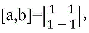
1、当UE0和UE1使用第一个梳的时候,UE0和UE1的DMRS pattern如图4 所示,UE0使用的DMRS pattern使用[a,b]=[1,1],UE1使用的DMRS pattern 使用[a,b]=[1,-1]。1. When UE0 and UE1 use the first comb, the DMRS pattern of UE0 and UE1 is shown in Figure 4. The DMRS pattern used by UE0 uses [a,b]=[1,1], and the DMRS pattern used by UE1 uses [a,b]=[1,-1].
2、当UE2和UE3使用第二个梳的时候,UE2和UE3的DMRS pattern如图 5所示,为UE2的DMRS pattern使用[a,b]=[1,1],UE3的DMRS pattern使用[a,b]=[1, -1]。2. When UE2 and UE3 use the second comb, the DMRS pattern of UE2 and UE3 is as shown in Figure 5. For the DMRS pattern of UE2, use [a,b]=[1,1], and the DMRS pattern of UE3 uses [ a,b]=[1, -1].
3、当UE4和UE5使用第三个梳的时候,UE4和UE5的DMRS pattern如图 6所示,UE4的DMRS pattern使用[a,b]=[1,1],UE5的DMRS pattern使用[a,b]=[1, -1]。3. When UE4 and UE5 use the third comb, the DMRS pattern of UE4 and UE5 is shown in Figure 6, the DMRS pattern of UE4 uses [a,b]=[1,1], and the DMRS pattern of UE5 uses [a ,b]=[1, -1].
4、当UE6和UE7使用第四个梳的时候,UE6和UE7的DMRS pattern如图 7所示,UE6的DMRS pattern使用[a,b]=[1,1],UE7的DMRS pattern使用[a,b]=[1, -1]。4. When UE6 and UE7 use the fourth comb, the DMRS pattern of UE6 and UE7 is shown in Figure 7. The DMRS pattern of UE6 uses [a,b]=[1,1], and the DMRS pattern of UE7 uses [a ,b]=[1, -1].
场景二:目标DMRS的配置方式为comb当comb为2,OCC的长度为4,目标OFDM符号位的个数为4。Scenario 2: The configuration mode of the target DMRS is comb when the comb is 2, the length of the OCC is 4, and the number of the target OFDM symbol bits is 4.
如图8所示,获得目标DMRS pattern的方法包括如下步骤包括:As shown in Figure 8, the method for obtaining the target DMRS pattern includes the following steps:
步骤801、从目标OFDM符号位中选取连续的两个OFDM符号位为第二待使用的OFDM符号位。Step 801: Select two consecutive OFDM symbol bits from the target OFDM symbol bits as the second to-be-used OFDM symbol bits.
如图9所示,目标OFDM符号位为OFDM0-OFDM3,步骤301可以从 OFDM0-OFDM3中任意选取2个连续的OFDM符号位作为第二待使用的OFDM 符号位。例如:选取OFDM0和OFDM1作为第二待使用的OFDM符号位,或者选取OFDM2和OFDM3作为第二待使用的OFDM符号位。需要说明的是,在本实施例中,OFDM0-OFDM3仅用于区分目标OFDM符号位中的4个OFDM位,并不是实际意义上的目标OFDM符号位的位置。As shown in FIG. 9 , the target OFDM symbol bits are OFDM0-OFDM3, and in step 301, two consecutive OFDM symbol bits may be arbitrarily selected from OFDM0-OFDM3 as the second to-be-used OFDM symbol bits. For example, OFDM0 and OFDM1 are selected as the second OFDM symbol bits to be used, or OFDM2 and OFDM3 are selected as the second OFDM symbol bits to be used. It should be noted that, in this embodiment, OFDM0-OFDM3 are only used to distinguish 4 OFDM bits in the target OFDM symbol bits, and are not the positions of the target OFDM symbol bits in the actual sense.
需要说明的是,图9仅以原OFDM符号位(OFDM0和OFDM1)和扩展后的OFDM(OFDM2和OFDM3)位置相邻设置为例进行说明,在实际的使用过程中也可以间隔设置,此处不做具体的说明。It should be noted that Fig. 9 only takes the adjacent setting of the original OFDM symbol bits (OFDM0 and OFDM1) and the expanded OFDM (OFDM2 and OFDM3) as an example for illustration, and can also be set at intervals in the actual use process, here No specific instructions are given.
步骤802、根据目标DMRS的配置方式、OCC和第二待使用的OFDM,获得目标DMRSpattern。Step 802: Obtain the target DMRS pattern according to the configuration mode of the target DMRS, the OCC, and the second OFDM to be used.
其中,OCC的长度为4,OCC码可表示
1、UE0-UE3的DMRS pattern如图10所示,UE0的DMRS pattern使用 [a,b,c,d]=[1,1,1,1];UE1的DMRS pattern使用[a,b,c,d]=[1,1,-1,-1];UE2的DMRS pattern使用[a,b,c,d]=[1,-1,1,-1];UE4的DMRS pattern使用[a,b,c,d]=[1,-1,-1,1]。1. The DMRS pattern of UE0-UE3 is shown in Figure 10. The DMRS pattern of UE0 uses [a,b,c,d]=[1,1,1,1]; the DMRS pattern of UE1 uses [a,b,c] ,d]=[1,1,-1,-1]; the DMRS pattern of UE2 uses [a,b,c,d]=[1,-1,1,-1]; the DMRS pattern of UE4 uses [a ,b,c,d]=[1,-1,-1,1].
2、UE4-UE7的DMRS pattern如图11所示,UE4的DMRS pattern使用 [a,b,c,d]=[1,1,1,1];UE5的DMRS pattern使用[a,b,c,d]=[1,1,-1,-1];UE6的DMRS pattern使用[a,b,c,d]=[1,-1,1,-1];UE7的DMRS pattern使用[a,b,c,d]=[1,-1,-1,1]。2. The DMRS pattern of UE4-UE7 is shown in Figure 11. The DMRS pattern of UE4 uses [a,b,c,d]=[1,1,1,1]; the DMRS pattern of UE5 uses [a,b,c] ,d]=[1,1,-1,-1]; the DMRS pattern of UE6 uses [a,b,c,d]=[1,-1,1,-1]; the DMRS pattern of UE7 uses [a ,b,c,d]=[1,-1,-1,1].
3、UE8-UE11的DMRS pattern如图12所示,UE8的DMRS pattern使用 [a,b,c,d]=[1,1,1,1];UE9的DMRS pattern使用[a,b,c,d]=[1,1,-1,-1];UE10的DMRS pattern使用[a,b,c,d]=[1,-1,1,-1];UE11的DMRS pattern使用[a,b,c,d]=[1,-1,-1,1]。3. The DMRS pattern of UE8-UE11 is shown in Figure 12. The DMRS pattern of UE8 uses [a,b,c,d]=[1,1,1,1]; the DMRS pattern of UE9 uses [a,b,c] ,d]=[1,1,-1,-1]; the DMRS pattern of UE10 uses [a,b,c,d]=[1,-1,1,-1]; the DMRS pattern of UE11 uses [a ,b,c,d]=[1,-1,-1,1].
4、UE12-UE15的DMRS pattern如图13所示,UE12的DMRS pattern使用 [a,b,c,d]=[1,1,1,1];UE13的DMRS pattern使用[a,b,c,d]=[1,1,-1,-1];UE14的DMRS pattern使用[a,b,c,d]=[1,-1,1,-1];UE15的DMRS pattern使用[a,b,c,d]=[1,-1,-1,1]。4. The DMRS pattern of UE12-UE15 is shown in Figure 13, the DMRS pattern of UE12 uses [a,b,c,d]=[1,1,1,1]; the DMRS pattern of UE13 uses [a,b,c] ,d]=[1,1,-1,-1]; the DMRS pattern of UE14 uses [a,b,c,d]=[1,-1,1,-1]; the DMRS pattern of UE15 uses [a ,b,c,d]=[1,-1,-1,1].
场景三:目标DMRS的配置方式为comb,comb为4,OCC的长度为4,目标OFDM符号位的个数为4。Scenario 3: The configuration mode of the target DMRS is comb, the comb is 4, the length of the OCC is 4, and the number of the target OFDM symbol bits is 4.
如图14所示,获得目标DMRS pattern的方法包括如下步骤:As shown in Figure 14, the method for obtaining the target DMRS pattern includes the following steps:
步骤1401,从目标OFDM符号位中获取全部的4个OFDM符号位为第三待使用的OFDM符号位。Step 1401: Obtain all four OFDM symbol bits from the target OFDM symbol bits as the third to-be-used OFDM symbol bits.
如图9所示,目标OFDM符号位为OFDM0-OFDM3,步骤1401可以获取全部的OFDM0-OFDM3作为第三待使用的OFDM符号位。需要说明的是,在本实施例中,OFDM0-OFDM3仅用于区分目标OFDM符号位中的4个OFDM位,并不是实际意义上的目标OFDM符号位的位置。As shown in FIG. 9 , the target OFDM symbol bits are OFDM0-OFDM3, and in
步骤1402、根据目标DMRS的配置方式、OCC和第三待使用的OFDM,获得目标DMRSpattern。Step 1402: Obtain the target DMRSpattern according to the configuration mode of the target DMRS, the OCC, and the third OFDM to be used.
其中,OCC的长度为4,OCC码可表示
1、UE0-UE3的DMRS pattern如图15所示,UE0的DMRS pattern使用 [a,b,c,d]=[1,1,1,1];UE1的DMRS pattern使用[a,b,c,d]=[1,1,-1,-1];UE2的DMRS pattern使用[a,b,c,d]=[1,-1,1,-1];UE4的DMRS pattern使用[a,b,c,d]=[1,-1,-1,1]。1. The DMRS pattern of UE0-UE3 is shown in Figure 15. The DMRS pattern of UE0 uses [a,b,c,d]=[1,1,1,1]; the DMRS pattern of UE1 uses [a,b,c] ,d]=[1,1,-1,-1]; the DMRS pattern of UE2 uses [a,b,c,d]=[1,-1,1,-1]; the DMRS pattern of UE4 uses [a ,b,c,d]=[1,-1,-1,1].
2、UE4-UE7的DMRS pattern如图16所示,UE4的DMRS pattern使用 [a,b,c,d]=[1,1,1,1];UE5的DMRS pattern使用[a,b,c,d]=[1,1,-1,-1];UE6的DMRS pattern使用[a,b,c,d]=[1,-1,1,-1];UE7的DMRS pattern使用[a,b,c,d]=[1,-1,-1,1]。2. The DMRS pattern of UE4-UE7 is shown in Figure 16. The DMRS pattern of UE4 uses [a,b,c,d]=[1,1,1,1]; the DMRS pattern of UE5 uses [a,b,c] ,d]=[1,1,-1,-1]; the DMRS pattern of UE6 uses [a,b,c,d]=[1,-1,1,-1]; the DMRS pattern of UE7 uses [a ,b,c,d]=[1,-1,-1,1].
3、UE8-UE11的DMRS pattern如图17所示,UE8的DMRS pattern使用 [a,b,c,d]=[1,1,1,1];UE9的DMRS pattern使用[a,b,c,d]=[1,1,-1,-1];UE10的DMRS pattern使用[a,b,c,d]=[1,-1,1,-1];UE11的DMRS pattern使用[a,b,c,d]=[1,-1,-1,1]。3. The DMRS pattern of UE8-UE11 is shown in Figure 17. The DMRS pattern of UE8 uses [a,b,c,d]=[1,1,1,1]; the DMRS pattern of UE9 uses [a,b,c] ,d]=[1,1,-1,-1]; the DMRS pattern of UE10 uses [a,b,c,d]=[1,-1,1,-1]; the DMRS pattern of UE11 uses [a ,b,c,d]=[1,-1,-1,1].
4、UE12-UE15的DMRS pattern如图18所示,UE12的DMRS pattern使用 [a,b,c,d]=[1,1,1,1];UE13的DMRS pattern使用[a,b,c,d]=[1,1,-1,-1];UE14的DMRS pattern使用[a,b,c,d]=[1,-1,1,-1];UE15的DMRS pattern使用[a,b,c,d]=[1,-1,-1,1]。4. The DMRS pattern of UE12-UE15 is shown in Figure 18. The DMRS pattern of UE12 uses [a,b,c,d]=[1,1,1,1]; the DMRS pattern of UE13 uses [a,b,c] ,d]=[1,1,-1,-1]; the DMRS pattern of UE14 uses [a,b,c,d]=[1,-1,1,-1]; the DMRS pattern of UE15 uses [a ,b,c,d]=[1,-1,-1,1].
场景四:目标DMRS的配置方式为FDM,目标OFDM符号位的个数为2或者4,OCC的长度为2。Scenario 4: The configuration mode of the target DMRS is FDM, the number of target OFDM symbol bits is 2 or 4, and the length of the OCC is 2.
如图19所示,获得目标DMRS pattern的方法包括如下步骤:As shown in Figure 19, the method for obtaining the target DMRS pattern includes the following steps:
步骤1901,如果目标OFDM符号位个数为2,从目标OFDM符号位中选取一个OFDM符号位为第四待使用的OFDM符号位,或者,如果目标OFDM符号位个数为4,从目标OFDM符号位中选取连续的两个OFDM符号位为第四待使用的OFDM符号位。
在本实施例中,如果目标OFDM符号位个数为2,目标OFDM符号位可以如图3所示,步骤1901的具体实现方法可以参见图2所示的步骤201所述,此处不再赘述。In this embodiment, if the number of target OFDM symbol bits is 2, the target OFDM symbol bits may be as shown in FIG. 3 , and the specific implementation method of
在本实施例,如果目标OFDM符号位个数为4,目标OFDM符号位可以如图9所示,步骤1901的具体实现方法可以参见图8所示的步骤801所述,此处不再赘述。In this embodiment, if the number of target OFDM symbol bits is 4, the target OFDM symbol bits may be as shown in FIG. 9 , and the specific implementation method of
步骤1902,根据目标DMRS的配置方式、OCC和第四待使用的OFDM,获得所述目标DMRS pattern。Step 1902: Obtain the target DMRS pattern according to the configuration mode of the target DMRS, the OCC, and the fourth OFDM to be used.
其中,OCC的长度为2,OCC码可以表示为
1、UE0和UE1的DMRS pattern如图20所示,UE0的DMRS pattern使用 [a,b]=[1,1];UE1的DMRS pattern使用[a,b]=[1,-1]。1. The DMRS patterns of UE0 and UE1 are shown in FIG. 20 . The DMRS pattern of UE0 uses [a,b]=[1,1]; the DMRS pattern of UE1 uses [a,b]=[1,-1].
2、UE2和UE3的DMRS pattern如图21所示,UE2的DMRS pattern使用 [a,b]=[1,1];UE3的DMRS pattern使用[a,b]=[1,-1]。2. The DMRS patterns of UE2 and UE3 are shown in FIG. 21 . The DMRS pattern of UE2 uses [a,b]=[1,1]; the DMRS pattern of UE3 uses [a,b]=[1,-1].
3、UE4和UE5的DMRS pattern如图22所示,UE4的DMRS pattern使用 [a,b]=[1,1];UE5的DMRS pattern使用[a,b]=[1,-1]。3. The DMRS patterns of UE4 and UE5 are shown in FIG. 22 . The DMRS pattern of UE4 uses [a,b]=[1,1]; the DMRS pattern of UE5 uses [a,b]=[1,-1].
4、UE6和UE7的DMRS pattern如图23所示,UE6的DMRS pattern使用 [a,b]=[1,1];UE7的DMRS pattern使用[a,b]=[1,-1]。4. The DMRS patterns of UE6 and UE7 are shown in FIG. 23 . The DMRS pattern of UE6 uses [a,b]=[1,1]; the DMRS pattern of UE7 uses [a,b]=[1,-1].
5、UE8和UE9的DMRS pattern如图24所示,UE8的DMRS pattern使用 [a,b]=[1,1];UE9的DMRS pattern使用[a,b]=[1,-1]。5. The DMRS patterns of UE8 and UE9 are shown in FIG. 24 . The DMRS pattern of UE8 uses [a,b]=[1,1]; the DMRS pattern of UE9 uses [a,b]=[1,-1].
6、UE10和UE11的DMRS pattern如图25所示,UE10的DMRS pattern使用[a,b]=[1,1];UE11的DMRS pattern使用[a,b]=[1,-1]。6. The DMRS patterns of UE10 and UE11 are shown in FIG. 25 . The DMRS pattern of UE10 uses [a,b]=[1,1]; the DMRS pattern of UE11 uses [a,b]=[1,-1].
在本实施例中,UE12-UE23的DMRS pattern与UE0-UE11的DMRS pattern 基本相同,其区别在于,UE0-UE11的第三待使用OFDM符号位为OFDM0和 OFDM1,而UE12-UE23的第三待使用OFDM符号位为OFDM2和OFDM3,此处不对UE12-UE23的DMRS pattern进行具体说明。In this embodiment, the DMRS pattern of UE12-UE23 is basically the same as the DMRS pattern of UE0-UE11, the difference is that the third to-be-used OFDM symbol bits of UE0-UE11 are OFDM0 and OFDM1, while the third to-be-used OFDM symbol bits of UE12-UE23 The OFDM symbol bits used are OFDM2 and OFDM3, and the DMRS pattern of UE12-UE23 is not specifically described here.
需要说明的是,在本实施例中,目标DMRS pattern均由两组以上相同的OCC 设置而成,一般情况下,每组OCC的顺序均相同,如:OCC长度为2时,OCC 的顺序均为a,b;OCC长度为4时,OCC的顺序均为a,b,c,d。It should be noted that, in this embodiment, the target DMRS pattern is set by more than two groups of identical OCCs. Generally, the order of each group of OCCs is the same. For example, when the OCC length is 2, the order of OCCs is the same. is a, b; when the OCC length is 4, the order of the OCC is a, b, c, d.
优选地,为了达到功率平衡的目的,本发明实施例提供的技术方案中,每组 OCC的顺序可以不同,例如:在图10所示的示例中,可以将第二组OCC的顺序设置为c,d,a,b,则此时,图10对应的DMRS pattern可以替换为图26所示。Preferably, in order to achieve the purpose of power balance, in the technical solution provided by the embodiment of the present invention, the order of each group of OCCs may be different. For example, in the example shown in FIG. 10 , the order of the second group of OCCs may be set to c ,d,a,b, then at this time, the DMRS pattern corresponding to FIG. 10 can be replaced with the one shown in FIG. 26 .
在本实施例中,当数据传输波形、DMRS配置类型以及DMRS符号的最大长度不同时,目标DMRS端口指示表也不相同。为了使本领域技术人员能够更清楚地理解本发明实施例提供的技术方案,下面分别对不同场景下目标DMRS 端口指示表进行详细说明:In this embodiment, when the data transmission waveform, the DMRS configuration type and the maximum length of the DMRS symbol are different, the target DMRS port indication table is also different. In order to enable those skilled in the art to more clearly understand the technical solutions provided by the embodiments of the present invention, the following describes the target DMRS port indication tables in different scenarios in detail:
场景一:scene one:
Antenna port(s),PUSCH-tp=EnabledAntenna port(s),PUSCH-tp=Enabled
UL-DMRS-config-type=1,UL-DMRS-max-len=1UL-DMRS-config-type=1, UL-DMRS-max-len=1
其中,Antenna port(s)为天线端口,PUSCH-tp=Enabled表示数据传输波形为单载波频分多址(Single-carrier Frequency-Division Multiple Access,SC-FDMA); UL-DMRS-config-type=1表示DMRS配置类型为梳状;UL-DMRS-max-len=1表示DMRS符号的最大长度为1。Wherein, Antenna port(s) is the antenna port, and PUSCH-tp=Enabled indicates that the data transmission waveform is Single-carrier Frequency-Division Multiple Access (SC-FDMA); UL-DMRS-config-type= 1 indicates that the DMRS configuration type is comb; UL-DMRS-max-len=1 indicates that the maximum length of the DMRS symbol is 1.
目标DMRS pattern可以如图4-7所示,预先设置的目标DMRS的端口为OFDM0对应的端口号为0-3,OFDM1对应的端口号为4-7,此时,目标DMRS 端口指示表可以如表1所示:The target DMRS pattern can be shown in Figure 4-7. The preset target DMRS ports are 0-3 corresponding to OFDM0 and 4-7 corresponding to OFDM1. At this time, the target DMRS port indication table can be as follows Table 1 shows:

表1Table 1
场景二:Scenario two:
Antenna port(s),PUSCH-tp=EnabledAntenna port(s),PUSCH-tp=Enabled
UL-DMRS-config-type=1,UL-DMRS-max-len=2UL-DMRS-config-type=1, UL-DMRS-max-len=2
其中,Antenna port(s)为天线端口,PUSCH-tp=Enabled表示数据传输波形为SC-FDMA;UL-DMRS-config-type=1表示DMRS配置类型为梳状; UL-DMRS-max-len=2表示DMRS符号的最大长度为2。Among them, Antenna port(s) is the antenna port, PUSCH-tp=Enabled indicates that the data transmission waveform is SC-FDMA; UL-DMRS-config-type=1 indicates that the DMRS configuration type is comb; UL-DMRS-max-len= 2 means that the maximum length of a DMRS symbol is 2.
目标DMRS pattern可以如图10-13所示,预先设置的目标DMRS的端口为 OFDM0和OFDM1对应的端口号为0-7,OFDM2和OFDM3对应的端口号为8-15,此时,目标DMRS端口指示表可以如表2所示:The target DMRS pattern can be shown in Figure 10-13. The preset target DMRS ports are 0-7 corresponding to OFDM0 and OFDM1, and 8-15 corresponding to OFDM2 and OFDM3. At this time, the target DMRS port The indicator table can be as shown in Table 2:
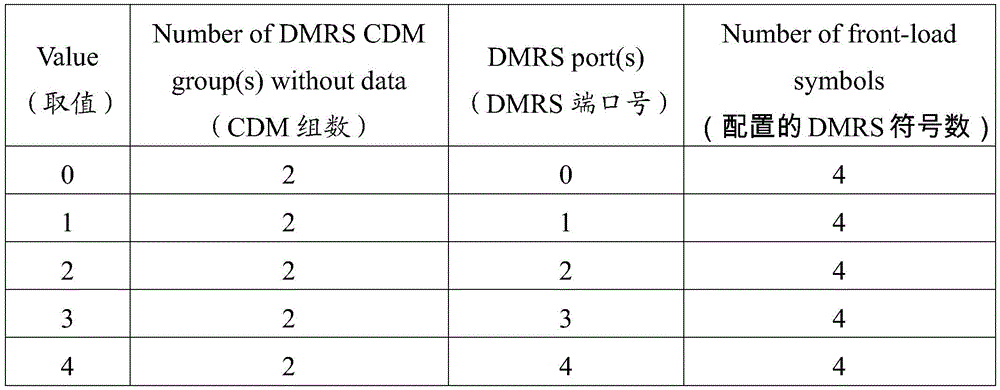

表2Table 2
场景三:Scenario three:
Antenna port(s),PUSCH-tp=EnabledAntenna port(s),PUSCH-tp=Enabled
UL-DMRS-config-type=1,UL-DMRS-max-len=4UL-DMRS-config-type=1, UL-DMRS-max-len=4
其中,Antenna port(s)为天线端口,PUSCH-tp=Enabled表示数据传输波形为SC-FDMA;UL-DMRS-config-type=1表示DMRS配置类型为梳状;UL-DMRS-max-len=4表示DMRS符号的最大长度为4。Among them, Antenna port(s) is the antenna port, PUSCH-tp=Enabled indicates that the data transmission waveform is SC-FDMA; UL-DMRS-config-type=1 indicates that the DMRS configuration type is comb; UL-DMRS-max-len= 4 means that the maximum length of a DMRS symbol is 4.
目标DMRS pattern可以如图10-13所示,预先设置的目标DMRS的端口为 OFDM0和OFDM1对应的端口号为0-7,OFDM2和OFDM3对应的端口号为8-15,此时,目标DMRS端口指示表可以如表3所示:The target DMRS pattern can be shown in Figure 10-13. The preset target DMRS ports are 0-7 corresponding to OFDM0 and OFDM1, and 8-15 corresponding to OFDM2 and OFDM3. At this time, the target DMRS port The indicator table can be as shown in Table 3:


表3table 3
场景四:Scenario four:
Antenna port(s),PUSCH-tp=Disabled,Antenna port(s),PUSCH-tp=Disabled,
UL-DMRS-config-type=1,UL-DMRS-max-len=1,rank=1UL-DMRS-config-type=1, UL-DMRS-max-len=1, rank=1
其中,Antenna port(s)为天线端口,PUSCH-tp=Disabled表示数据传输波形为循环前缀正交频分复用(Cyclic-PrefixOrthogonal Frequency Division Multiplexing,CP-OFDM),UL-DMRS-config-type=1表示DMRS配置类型为梳状; UL-DMRS-max-len=1表示DMRS符号的最大长度为1,rank=1表示信道秩数为 1。Among them, Antenna port(s) is the antenna port, PUSCH-tp=Disabled indicates that the data transmission waveform is Cyclic-Prefix Orthogonal Frequency Division Multiplexing (CP-OFDM), UL-DMRS-config-type= 1 indicates that the DMRS configuration type is comb; UL-DMRS-max-len=1 indicates that the maximum length of the DMRS symbol is 1, and rank=1 indicates that the channel rank number is 1.
目标DMRS pattern可以如图4-7所示,预先设置的目标DMRS的端口为 OFDM0对应的端口号为0-3,OFDM1对应的端口号为4-7,此时,目标DMRS 端口指示表可以如表4所示:The target DMRS pattern can be shown in Figure 4-7. The preset target DMRS ports are 0-3 corresponding to OFDM0 and 4-7 corresponding to OFDM1. At this time, the target DMRS port indication table can be as follows Table 4 shows:

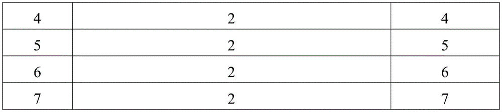
表4Table 4
场景五:Scenario five:
Antenna port(s),PUSCH-tp=Disabled,Antenna port(s),PUSCH-tp=Disabled,
UL-DMRS-config-type=1,UL-DMRS-max-len=1,rank=2UL-DMRS-config-type=1, UL-DMRS-max-len=1, rank=2
其中,Antenna port(s)为天线端口,PUSCH-tp=Disabled表示数据传输波形为CP-OFDM,UL-DMRS-config-type=1表示DMRS配置类型为梳状; UL-DMRS-max-len=1表示DMRS符号的最大长度为1,rank=2表示信道秩数为 2。Among them, Antenna port(s) is the antenna port, PUSCH-tp=Disabled indicates that the data transmission waveform is CP-OFDM, and UL-DMRS-config-type=1 indicates that the DMRS configuration type is comb; UL-DMRS-max-len= 1 indicates that the maximum length of the DMRS symbol is 1, and rank=2 indicates that the channel rank is 2.
目标DMRS pattern可以如图4-7所示,预先设置的目标DMRS的端口为 OFDM0对应的端口号为0-3,OFDM1对应的端口号为4-7,此时,目标DMRS 端口指示表可以如表5所示:The target DMRS pattern can be shown in Figure 4-7. The preset target DMRS ports are 0-3 corresponding to OFDM0 and 4-7 corresponding to OFDM1. At this time, the target DMRS port indication table can be as follows Table 5 shows:
表5table 5
场景六:Scenario six:
Antenna port(s),PUSCH-tp=Disabled,Antenna port(s),PUSCH-tp=Disabled,
UL-DMRS-config-type=1,UL-DMRS-max-len=1,rank=3UL-DMRS-config-type=1, UL-DMRS-max-len=1, rank=3
其中,Antenna port(s)为天线端口,PUSCH-tp=Disabled表示数据传输波形为CP-OFDM,UL-DMRS-config-type=1表示DMRS配置类型为梳状; UL-DMRS-max-len=1表示DMRS符号最大长度为1,rank=3表示信道秩数为3。Among them, Antenna port(s) is the antenna port, PUSCH-tp=Disabled indicates that the data transmission waveform is CP-OFDM, and UL-DMRS-config-type=1 indicates that the DMRS configuration type is comb; UL-DMRS-max-len= 1 indicates that the maximum length of the DMRS symbol is 1, and rank=3 indicates that the channel rank number is 3.
目标DMRS pattern可以如图4-7所示,预先设置的目标DMRS的端口为 OFDM0对应的端口号为0-3,OFDM1对应的端口号为4-7,此时,目标DMRS 端口指示表可以如表6所示:The target DMRS pattern can be shown in Figure 4-7. The preset target DMRS ports are 0-3 corresponding to OFDM0 and 4-7 corresponding to OFDM1. At this time, the target DMRS port indication table can be as follows Table 6 shows:
表6Table 6
场景七:Scenario Seven:
Antenna port(s),PUSCH-tp=Disabled,Antenna port(s),PUSCH-tp=Disabled,
UL-DMRS-config-type=1,UL-DMRS-max-len=1,rank=4UL-DMRS-config-type=1, UL-DMRS-max-len=1, rank=4
其中,Antenna port(s)为天线端口,PUSCH-tp=Disabled表示数据传输波形为CP-OFDM,UL-DMRS-config-type=1表示DMRS配置类型为梳状; UL-DMRS-max-len=1表示DMRS符号的最大长度为1,rank=4表示信道秩数为 4。Among them, Antenna port(s) is the antenna port, PUSCH-tp=Disabled indicates that the data transmission waveform is CP-OFDM, and UL-DMRS-config-type=1 indicates that the DMRS configuration type is comb; UL-DMRS-max-len= 1 indicates that the maximum length of the DMRS symbol is 1, and rank=4 indicates that the channel rank number is 4.
目标DMRS pattern可以如图4-7所示,预先设置的目标DMRS的端口为 OFDM0对应的端口号为0-3,OFDM1对应的端口号为4-7,此时,目标DMRS 端口指示表可以如表7所示:The target DMRS pattern can be shown in Figure 4-7. The preset target DMRS ports are 0-3 corresponding to OFDM0 and 4-7 corresponding to OFDM1. At this time, the target DMRS port indication table can be as follows Table 7 shows:


表7Table 7
场景八:Scene Eight:
Antenna port(s),PUSCH-tp=Disabled,Antenna port(s),PUSCH-tp=Disabled,
UL-DMRS-config-type=1,UL-DMRS-max-len=2,rank=1UL-DMRS-config-type=1, UL-DMRS-max-len=2, rank=1
其中,Antenna port(s)为天线端口,PUSCH-tp=Disabled表示数据传输波形为CP-OFDM,UL-DMRS-config-type=1表示DMRS配置类型为梳状; UL-DMRS-max-len=2表示DMRS符号最大长度为2,rank=1表示信道秩数为1。Among them, Antenna port(s) is the antenna port, PUSCH-tp=Disabled indicates that the data transmission waveform is CP-OFDM, and UL-DMRS-config-type=1 indicates that the DMRS configuration type is comb; UL-DMRS-max-len= 2 indicates that the maximum length of the DMRS symbol is 2, and rank=1 indicates that the channel rank is 1.
目标DMRS pattern可以如图10-13所示,预先设置的目标DMRS的端口为 OFDM0和OFDM1对应的端口号为0-7,OFDM2和OFDM3对应的端口号为8-15,此时,目标DMRS端口指示表可以如表8所示:The target DMRS pattern can be shown in Figure 10-13. The preset target DMRS ports are 0-7 corresponding to OFDM0 and OFDM1, and 8-15 corresponding to OFDM2 and OFDM3. At this time, the target DMRS port The indicator table can be as shown in Table 8:


表8Table 8
场景九:Scene Nine:
Antenna port(s),PUSCH-tp=Disabled,Antenna port(s),PUSCH-tp=Disabled,
UL-DMRS-config-type=1,UL-DMRS-max-len=4,rank=1UL-DMRS-config-type=1, UL-DMRS-max-len=4, rank=1
其中,Antenna port(s)为天线端口,PUSCH-tp=Disabled表示数据传输波形为CP-OFDM,UL-DMRS-config-type=1表示DMRS配置类型为梳状;UL-DMRS-max-len=4表示DMRS符号最大长度为4,rank=1表示信道秩数为1。Among them, Antenna port(s) is the antenna port, PUSCH-tp=Disabled indicates that the data transmission waveform is CP-OFDM, UL-DMRS-config-type=1 indicates that the DMRS configuration type is comb; UL-DMRS-max-len= 4 indicates that the maximum length of the DMRS symbol is 4, and rank=1 indicates that the channel rank number is 1.
目标DMRS pattern可以如图10-13所示,预先设置的目标DMRS的端口为 OFDM0和OFDM1对应的端口号为0-7,OFDM2和OFDM3对应的端口号为8-15,此时,目标DMRS端口指示表可以如表9所示:The target DMRS pattern can be shown in Figure 10-13. The preset target DMRS ports are 0-7 corresponding to OFDM0 and OFDM1, and 8-15 corresponding to OFDM2 and OFDM3. At this time, the target DMRS port The indicator table can be as shown in Table 9:

表9Table 9
场景十:Scene ten:
Antenna port(s),PUSCH-tp=Disabled,Antenna port(s),PUSCH-tp=Disabled,
UL-DMRS-config-type=1,UL-DMRS-max-len=2,rank=2UL-DMRS-config-type=1, UL-DMRS-max-len=2, rank=2
其中,Antenna port(s)为天线端口,PUSCH-tp=Disabled表示数据传输波形为CP-OFDM,UL-DMRS-config-type=1表示DMRS配置类型为梳状; UL-DMRS-max-len=2表示DMRS符号最大长度为2,rank=2表示信道秩数为2。Among them, Antenna port(s) is the antenna port, PUSCH-tp=Disabled indicates that the data transmission waveform is CP-OFDM, and UL-DMRS-config-type=1 indicates that the DMRS configuration type is comb; UL-DMRS-max-len= 2 indicates that the maximum length of the DMRS symbol is 2, and rank=2 indicates that the channel rank is 2.
目标DMRS pattern可以如图10-13所示,预先设置的目标DMRS的端口为 OFDM0和OFDM1对应的端口号为0-7,OFDM2和OFDM3对应的端口号为8-15,此时,目标DMRS端口指示表可以如表10所示:The target DMRS pattern can be shown in Figure 10-13. The preset target DMRS ports are 0-7 corresponding to OFDM0 and OFDM1, and 8-15 corresponding to OFDM2 and OFDM3. At this time, the target DMRS port The indicator table can be as shown in Table 10:

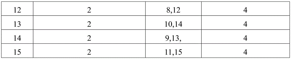
表10Table 10
场景十一:Scene eleven:
Antenna port(s),PUSCH-tp=Disabled,Antenna port(s),PUSCH-tp=Disabled,
UL-DMRS-config-type=1,UL-DMRS-max-len=4,rank=2UL-DMRS-config-type=1, UL-DMRS-max-len=4, rank=2
其中,Antenna port(s)为天线端口,PUSCH-tp=Disabled表示数据传输波形为CP-OFDM,UL-DMRS-config-type=1表示DMRS配置类型为梳状; UL-DMRS-max-len=4表示DMRS符号最大长度为4,rank=2表示信道秩数为2。Among them, Antenna port(s) is the antenna port, PUSCH-tp=Disabled indicates that the data transmission waveform is CP-OFDM, and UL-DMRS-config-type=1 indicates that the DMRS configuration type is comb; UL-DMRS-max-len= 4 indicates that the maximum length of the DMRS symbol is 4, and rank=2 indicates that the channel rank is 2.
目标DMRS pattern可以如图10-13所示,预先设置的目标DMRS的端口为 OFDM0和OFDM1对应的端口号为0-7,OFDM2和OFDM3对应的端口号为8-15,此时,目标DMRS端口指示表可以如表11所示:The target DMRS pattern can be shown in Figure 10-13. The preset target DMRS ports are 0-7 corresponding to OFDM0 and OFDM1, and 8-15 corresponding to OFDM2 and OFDM3. At this time, the target DMRS port The indicator table can be as shown in Table 11:


表11Table 11
场景十二:Scene twelve:
Antenna port(s),PUSCH-tp=Disabled,Antenna port(s),PUSCH-tp=Disabled,
UL-DMRS-config-type=1,UL-DMRS-max-len=2,rank=3UL-DMRS-config-type=1, UL-DMRS-max-len=2, rank=3
其中,Antenna port(s)为天线端口,PUSCH-tp=Disabled表示数据传输波形为CP-OFDM,UL-DMRS-config-type=1表示DMRS配置类型为梳状; UL-DMRS-max-len=2表示DMRS符号最大长度为2,rank=3表示信道秩数为3。Among them, Antenna port(s) is the antenna port, PUSCH-tp=Disabled indicates that the data transmission waveform is CP-OFDM, and UL-DMRS-config-type=1 indicates that the DMRS configuration type is comb; UL-DMRS-max-len= 2 indicates that the maximum length of the DMRS symbol is 2, and rank=3 indicates that the channel rank number is 3.
目标DMRS pattern可以如图10-13所示,预先设置的目标DMRS的端口为 OFDM0和OFDM1对应的端口号为0-7,OFDM2和OFDM3对应的端口号为8-15,此时,目标DMRS端口指示表可以如表12所示:The target DMRS pattern can be shown in Figure 10-13. The preset target DMRS ports are 0-7 corresponding to OFDM0 and OFDM1, and 8-15 corresponding to OFDM2 and OFDM3. At this time, the target DMRS port The indicator table can be as shown in Table 12:

表12Table 12
场景十三:Scene Thirteen:
Antenna port(s),PUSCH-tp=Disabled,Antenna port(s),PUSCH-tp=Disabled,
UL-DMRS-config-type=1,UL-DMRS-max-len=4,rank=3UL-DMRS-config-type=1, UL-DMRS-max-len=4, rank=3
其中,Antenna port(s)为天线端口,PUSCH-tp=Disabled表示数据传输波形为CP-OFDM,UL-DMRS-config-type=1表示DMRS配置类型为梳状; UL-DMRS-max-len=4表示DMRS符号最大长度为4,rank=3表示信道秩数为3。Among them, Antenna port(s) is the antenna port, PUSCH-tp=Disabled indicates that the data transmission waveform is CP-OFDM, and UL-DMRS-config-type=1 indicates that the DMRS configuration type is comb; UL-DMRS-max-len= 4 indicates that the maximum length of the DMRS symbol is 4, and rank=3 indicates that the channel rank number is 3.
目标DMRS pattern可以如图10-13所示,预先设置的目标DMRS的端口为 OFDM0和OFDM1对应的端口号为0-7,OFDM2和OFDM3对应的端口号为8-15,此时,目标DMRS端口指示表可以如表13所示:The target DMRS pattern can be shown in Figure 10-13. The preset target DMRS ports are 0-7 corresponding to OFDM0 and OFDM1, and 8-15 corresponding to OFDM2 and OFDM3. At this time, the target DMRS port The indicator table can be as shown in Table 13:

表13Table 13
场景十四:Scene Fourteen:
Antenna port(s),PUSCH-tp=Disabled,Antenna port(s),PUSCH-tp=Disabled,
UL-DMRS-config-type=1,UL-DMRS-max-len=2,rank=4UL-DMRS-config-type=1, UL-DMRS-max-len=2, rank=4
其中,Antenna port(s)为天线端口,PUSCH-tp=Disabled表示数据传输波形为CP-OFDM,UL-DMRS-config-type=1表示DMRS配置类型为梳状; UL-DMRS-max-len=2表示DMRS符号最大长度为2,rank=4表示信道秩数为4。Among them, Antenna port(s) is the antenna port, PUSCH-tp=Disabled indicates that the data transmission waveform is CP-OFDM, and UL-DMRS-config-type=1 indicates that the DMRS configuration type is comb; UL-DMRS-max-len= 2 indicates that the maximum length of the DMRS symbol is 2, and rank=4 indicates that the channel rank number is 4.
目标DMRS pattern可以如10-13所示,预先设置的目标DMRS的端口为 OFDM0和OFDM1对应的端口号为0-7,OFDM2和OFDM3对应的端口号为8-15,此时,目标DMRS端口指示表可以如表14所示:The target DMRS pattern can be shown in 10-13. The preset target DMRS ports are 0-7 corresponding to OFDM0 and OFDM1, and 8-15 corresponding to OFDM2 and OFDM3. At this time, the target DMRS port indicates The table can be as shown in Table 14:
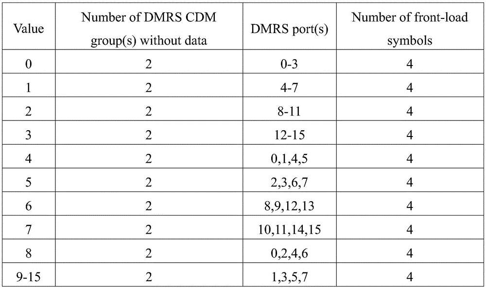
表14Table 14
场景十五:Scene fifteen:
Antenna port(s),PUSCH-tp=Disabled,Antenna port(s),PUSCH-tp=Disabled,
UL-DMRS-config-type=1,UL-DMRS-max-len=4,rank=4UL-DMRS-config-type=1, UL-DMRS-max-len=4, rank=4
其中,Antenna port(s)为天线端口,PUSCH-tp=Disabled表示数据传输波形为CP-OFDM,UL-DMRS-config-type=1表示DMRS配置类型为梳状; UL-DMRS-max-len=4表示DMRS符号最大长度为4,rank=4表示信道秩数为4。Among them, Antenna port(s) is the antenna port, PUSCH-tp=Disabled indicates that the data transmission waveform is CP-OFDM, and UL-DMRS-config-type=1 indicates that the DMRS configuration type is comb; UL-DMRS-max-len= 4 indicates that the maximum length of the DMRS symbol is 4, and rank=4 indicates that the channel rank number is 4.
目标DMRS pattern可以如图10-13所示,预先设置的目标DMRS的端口为 OFDM0和OFDM1对应的端口号为0-7,OFDM2和OFDM3对应的端口号为8-15,此时,目标DMRS端口指示表可以如表15所示:The target DMRS pattern can be shown in Figure 10-13. The preset target DMRS ports are 0-7 corresponding to OFDM0 and OFDM1, and 8-15 corresponding to OFDM2 and OFDM3. At this time, the target DMRS port The indicator table can be as shown in Table 15:

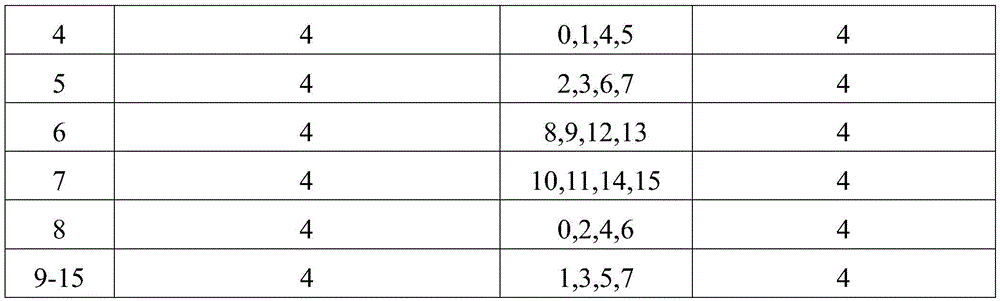
表15Table 15
场景十六:Scene sixteen:
Antenna port(s),PUSCH-tp=Disabled,Antenna port(s),PUSCH-tp=Disabled,
UL-DMRS-config-type=2,UL-DMRS-max-len=1,rank=1UL-DMRS-config-type=2, UL-DMRS-max-len=1, rank=1
其中,Antenna port(s)为天线端口,PUSCH-tp=Disabled表示数据传输波形为CP-OFDM,UL-DMRS-config-type=2表示DMRS配置类型为FDM; UL-DMRS-max-len=1表示DMRS符号最大长度为1,rank=1表示信道秩数为1。Among them, Antenna port(s) is the antenna port, PUSCH-tp=Disabled means that the data transmission waveform is CP-OFDM, UL-DMRS-config-type=2 means that the DMRS configuration type is FDM; UL-DMRS-max-len=1 Indicates that the maximum length of the DMRS symbol is 1, and rank=1 indicates that the channel rank is 1.
目标DMRS pattern可以如图20-25所示,需要说明的是,由于DMRS最大长度为1,所以在本实施例中,DMRS只占用2个OFDM符号位(OFDM0和 OFDM1),预先设置的目标DMRS的端口为OFDM0对应的端口号为0-5,OFDM1 对应的端口号为6-11,此时,目标DMRS端口指示表可以如表16所示:The target DMRS pattern can be shown in Figure 20-25. It should be noted that since the maximum length of the DMRS is 1, in this embodiment, the DMRS only occupies 2 OFDM symbol bits (OFDM0 and OFDM1). The preset target DMRS The port number corresponding to OFDM0 is 0-5, and the port number corresponding to OFDM1 is 6-11. At this time, the target DMRS port indication table can be as shown in Table 16:
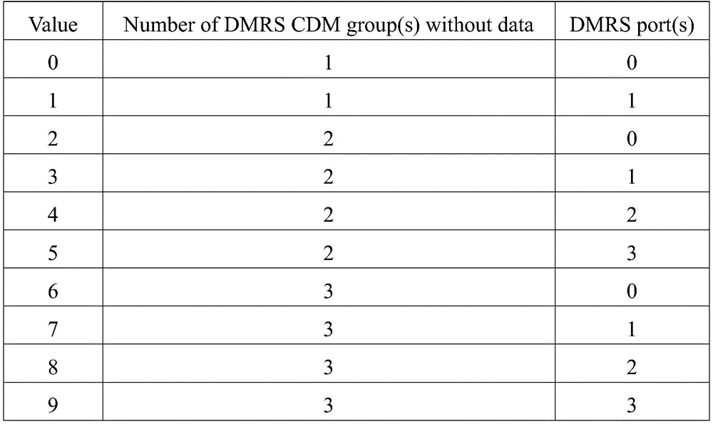
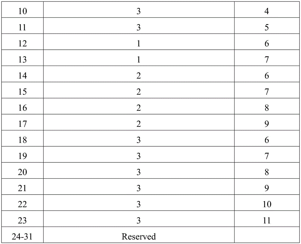
表16Table 16
优选地,DMRS所在符号的CDM组数可以灵活配置,对应不同的用户复用数量,如表16所示。Preferably, the number of CDM groups of the symbol where the DMRS is located can be flexibly configured to correspond to different user multiplexing numbers, as shown in Table 16.
场景十七:Scene seventeen:
Antenna port(s),PUSCH-tp=Disabled,Antenna port(s),PUSCH-tp=Disabled,
UL-DMRS-config-type=2,UL-DMRS-max-len=1,rank=2UL-DMRS-config-type=2, UL-DMRS-max-len=1, rank=2
其中,Antenna port(s)为天线端口,PUSCH-tp=Disabled表示数据传输波形为CP-OFDM,UL-DMRS-config-type=2表示DMRS配置类型为FDM; UL-DMRS-max-len=1表示DMRS符号最大长度为1,rank=2表示列数为2。Among them, Antenna port(s) is the antenna port, PUSCH-tp=Disabled means that the data transmission waveform is CP-OFDM, UL-DMRS-config-type=2 means that the DMRS configuration type is FDM; UL-DMRS-max-len=1 Indicates that the maximum length of the DMRS symbol is 1, and rank=2 indicates that the number of columns is 2.
目标DMRS pattern可以如图20-25所示,需要说明的是,由于DMRS最大长度为1,所以在本实施例中,DMRS只占用2个OFDM符号位(OFDM0和 OFDM1),预先设置的目标DMRS的端口为OFDM0对应的端口号为0-5,OFDM1 对应的端口号为6-11,此时,目标DMRS端口指示表可以如表17所示:The target DMRS pattern can be shown in Figure 20-25. It should be noted that since the maximum length of the DMRS is 1, in this embodiment, the DMRS only occupies 2 OFDM symbol bits (OFDM0 and OFDM1). The preset target DMRS The port number corresponding to OFDM0 is 0-5, and the port number corresponding to OFDM1 is 6-11. At this time, the target DMRS port indication table can be as shown in Table 17:
表17Table 17
优选地,DMRS所在符号的CDM组数可以灵活配置,对应不同的用户复用数量,如表17所示。Preferably, the number of CDM groups of the symbol where the DMRS is located can be flexibly configured, corresponding to different user multiplexing numbers, as shown in Table 17.
场景十八:Scene Eighteen:
Antenna port(s),PUSCH-tp=Disabled,Antenna port(s),PUSCH-tp=Disabled,
UL-DMRS-config-type=2,UL-DMRS-max-len=1,rank=3UL-DMRS-config-type=2, UL-DMRS-max-len=1, rank=3
其中,Antenna port(s)为天线端口,PUSCH-tp=Disabled表示数据传输波形为CP-OFDM,UL-DMRS-config-type=2表示DMRS配置类型为FDM; UL-DMRS-max-len=1表示DMRS符号最大长度为1,rank=3表示信道秩数为3。Among them, Antenna port(s) is the antenna port, PUSCH-tp=Disabled means that the data transmission waveform is CP-OFDM, UL-DMRS-config-type=2 means that the DMRS configuration type is FDM; UL-DMRS-max-len=1 Indicates that the maximum length of the DMRS symbol is 1, and rank=3 indicates that the channel rank number is 3.
目标DMRS pattern可以如步骤1902中所述的情况,需要说明的是,由于 DMRS最大长度为1,所以在本实施例中,DMRS只占用2个OFDM符号位 (OFDM0和OFDM1),预先设置的目标DMRS的端口为OFDM0对应的端口号为0-5,OFDM1对应的端口号为6-11,此时,目标DMRS端口指示表可以如表 18所示:The target DMRS pattern can be as described in
表18Table 18
优选地,DMRS所在符号的CDM组数可以灵活配置,对应不同的用户复用数量,如表18所示。Preferably, the number of CDM groups of the symbol where the DMRS is located can be flexibly configured, corresponding to different user multiplexing numbers, as shown in Table 18.
场景十九:Scene Nineteen:
Antenna port(s),PUSCH-tp=Disabled,Antenna port(s),PUSCH-tp=Disabled,
UL-DMRS-config-type=2,UL-DMRS-max-len=1,rank=4UL-DMRS-config-type=2, UL-DMRS-max-len=1, rank=4
其中,Antenna port(s)为天线端口,PUSCH-tp=Disabled表示数据传输波形为CP-OFDM,UL-DMRS-config-type=2表示DMRS配置类型为FDM; UL-DMRS-max-len=1表示DMRS符号最大长度为1,rank=4表示信道秩数为4。Among them, Antenna port(s) is the antenna port, PUSCH-tp=Disabled means that the data transmission waveform is CP-OFDM, UL-DMRS-config-type=2 means that the DMRS configuration type is FDM; UL-DMRS-max-len=1 Indicates that the maximum length of the DMRS symbol is 1, and rank=4 indicates that the channel rank number is 4.
目标DMRS pattern可以如步骤1902中所述的情况,需要说明的是,由于 DMRS最大长度为1,所以在本实施例中,DMRS只占用2个OFDM符号位 (OFDM0和OFDM1),预先设置的目标DMRS的端口为OFDM0对应的端口号为0-5,OFDM1对应的端口号为6-11,此时,目标DMRS端口指示表可以如表 19所示:The target DMRS pattern can be as described in


表19Table 19
优选地,DMRS所在符号的CDM组数可以灵活配置,对应不同的用户复用数量,如表19所示。Preferably, the number of CDM groups of the symbol where the DMRS is located can be flexibly configured, corresponding to different user multiplexing numbers, as shown in Table 19.
场景二十:Scene twenty:
Antenna port(s),PUSCH-tp=Disabled,Antenna port(s),PUSCH-tp=Disabled,
UL-DMRS-config-type=2,UL-DMRS-max-len=2,rank=1UL-DMRS-config-type=2, UL-DMRS-max-len=2, rank=1
其中,Antenna port(s)为天线端口,PUSCH-tp=Disabled表示数据传输波形为CP-OFDM,UL-DMRS-config-type=2表示DMRS配置类型为FDM; UL-DMRS-max-len=2表示DMRS符号最大长度为2,rank=1表示信道秩数为1。Among them, Antenna port(s) is the antenna port, PUSCH-tp=Disabled means that the data transmission waveform is CP-OFDM, UL-DMRS-config-type=2 means that the DMRS configuration type is FDM; UL-DMRS-max-len=2 Indicates that the maximum length of the DMRS symbol is 2, and rank=1 indicates that the channel rank is 1.
目标DMRS pattern可以如步骤1902中所述的情况,预先设置的目标DMRS 的端口为OFDM0和OFDM1对应的端口号为0-11,OFDM2和OFDM3对应的端口号为12-23,此时,目标DMRS端口指示表可以如表20表示:The target DMRS pattern can be as described in


表20Table 20
优选地,DMRS所在符号的CDM组数可以灵活配置,对应不同的用户复用数量,如表20所示。Preferably, the number of CDM groups of the symbol where the DMRS is located can be flexibly configured to correspond to different user multiplexing numbers, as shown in Table 20.
场景二十一:Scene twenty one:
Antenna port(s),PUSCH-tp=Disabled,Antenna port(s),PUSCH-tp=Disabled,
UL-DMRS-config-type=2,UL-DMRS-max-len=2,rank=2UL-DMRS-config-type=2, UL-DMRS-max-len=2, rank=2
其中,Antenna port(s)为天线端口,PUSCH-tp=Disabled表示数据传输波形为CP-OFDM,UL-DMRS-config-type=2表示DMRS配置类型为FDM; UL-DMRS-max-len=2表示DMRS符号最大长度为2,rank=2表示信道秩数为2。Among them, Antenna port(s) is the antenna port, PUSCH-tp=Disabled means that the data transmission waveform is CP-OFDM, UL-DMRS-config-type=2 means that the DMRS configuration type is FDM; UL-DMRS-max-len=2 Indicates that the maximum length of the DMRS symbol is 2, and rank=2 indicates that the channel rank is 2.
目标DMRS pattern可以如步骤1902中所述的情况,预先设置的目标DMRS 的端口为OFDM0和OFDM1对应的端口号为0-11,OFDM2和OFDM3对应的端口号为12-23,此时,目标DMRS端口指示表可以如表21所示:The target DMRS pattern can be as described in
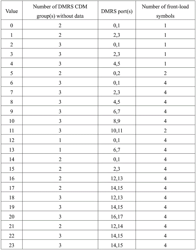
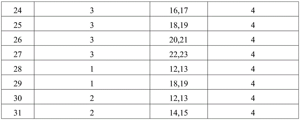
表21Table 21
优选地,DMRS所在符号的CDM组数可以灵活配置,对应不同的用户复用数量,如表21所示。Preferably, the number of CDM groups of the symbol where the DMRS is located can be flexibly configured to correspond to different user multiplexing numbers, as shown in Table 21.
场景二十二:Scene twenty-two:
Antenna port(s),PUSCH-tp=Disabled,Antenna port(s),PUSCH-tp=Disabled,
UL-DMRS-config-type=2,UL-DMRS-max-len=2,rank=3UL-DMRS-config-type=2, UL-DMRS-max-len=2, rank=3
其中,Antenna port(s)为天线端口,PUSCH-tp=Disabled表示数据传输波形为CP-OFDM,UL-DMRS-config-type=2表示DMRS配置类型为FDM; UL-DMRS-max-len=2表示DMRS符号最大长度为2,rank=3表示信道秩数为3。Among them, Antenna port(s) is the antenna port, PUSCH-tp=Disabled means that the data transmission waveform is CP-OFDM, UL-DMRS-config-type=2 means that the DMRS configuration type is FDM; UL-DMRS-max-len=2 Indicates that the maximum length of the DMRS symbol is 2, and rank=3 indicates that the channel rank number is 3.
目标DMRS pattern可以如步骤1902中所述的情况,预先设置的目标DMRS 的端口为OFDM0和OFDM1对应的端口号为0-11,OFDM2和OFDM3对应的端口号为12-23,此时,目标DMRS端口指示表可以如表22所示:The target DMRS pattern can be as described in

表22Table 22
优选地,DMRS所在符号的CDM组数可以灵活配置,对应不同的用户复用数量,如表22所示。Preferably, the number of CDM groups of the symbol where the DMRS is located can be flexibly configured, corresponding to different user multiplexing numbers, as shown in Table 22.
场景二十三:Scene twenty-three:
Antenna port(s),PUSCH-tp=Disabled,Antenna port(s),PUSCH-tp=Disabled,
UL-DMRS-config-type=2,UL-DMRS-max-len=2,rank=4UL-DMRS-config-type=2, UL-DMRS-max-len=2, rank=4
其中,Antenna port(s)为天线端口,PUSCH-tp=Disabled表示数据传输波形为CP-OFDM,UL-DMRS-config-type=2表示DMRS配置类型为FDM; UL-DMRS-max-len=2表示DMRS符号最大长度为2,rank=4表示信道秩数为4。Among them, Antenna port(s) is the antenna port, PUSCH-tp=Disabled means that the data transmission waveform is CP-OFDM, UL-DMRS-config-type=2 means that the DMRS configuration type is FDM; UL-DMRS-max-len=2 Indicates that the maximum length of the DMRS symbol is 2, and rank=4 indicates that the channel rank is 4.
目标DMRS pattern可以如步骤1902中所述的情况,预先设置的目标DMRS 的端口为OFDM0和OFDM1对应的端口号为0-11,OFDM2和OFDM3对应的端口号为12-23,此时,目标DMRS端口指示表可以如表23所示:The target DMRS pattern can be as described in


表23Table 23
优选地,DMRS所在符号的CDM组数可以灵活配置,对应不同的用户复用数量,如表23所示。Preferably, the number of CDM groups of the symbol where the DMRS is located can be flexibly configured, corresponding to different user multiplexing numbers, as shown in Table 23.
步骤102、根据目标DMRS端口指示表,向UE发送DMRS指示信息,以使得UE根据DMRS指示信息传输数据。Step 102: Send DMRS indication information to the UE according to the target DMRS port indication table, so that the UE transmits data according to the DMRS indication information.
在本实施例中,DMRS指示信息承载在DL DCI中,DMRS指示信息可以包括:DMRS端口,DMRS符号数,DMRS所在符号的CDM组等信息。In this embodiment, the DMRS indication information is carried in the DL DCI, and the DMRS indication information may include information such as the DMRS port, the number of DMRS symbols, and the CDM group of the symbol where the DMRS is located.
本发明实施例提供的技术方案,目标OFDM符号位相较于原DMRS使用的原OFDM符号位的个数增加了,使得根据目标OFDM符号位以及预先设置的正交掩码OCC生成的目标DMRSpattern个数也增加了,进而增加了目标DMRS 端口的数量,解决了现有技术DMRS数量无法满足日益增加的用户终端的数量的问题。由于DMRS数量增加了,降低了用户终端采用NOMA技术传输数据的干扰和冲突。According to the technical solution provided by the embodiment of the present invention, the number of target OFDM symbol bits is increased compared with the number of original OFDM symbol bits used by the original DMRS, so that the number of target DMRSpatterns generated according to the target OFDM symbol bits and the preset orthogonal mask OCC The number of target DMRS ports is also increased, thereby increasing the number of target DMRS ports, which solves the problem that the number of DMRSs in the prior art cannot meet the increasing number of user terminals. Since the number of DMRSs increases, the interference and collision of data transmitted by the user terminal using the NOMA technology are reduced.
如图27所示,本发明另一实施例还提供一种DMRS的指示方法,包括:As shown in FIG. 27, another embodiment of the present invention further provides a DMRS indication method, including:
步骤2701、获取目标DMRS pattern对应的目标DMRS端口指示表,其中,目标DMRSpattern由降低原DMRSpattern中DMRS的密度获得。Step 2701: Obtain a target DMRS port indication table corresponding to the target DMRS pattern, wherein the target DMRS pattern is obtained by reducing the density of DMRSs in the original DMRS pattern.
为了使本领域技术人员能够更清楚地理解目标DMRSpattern获取方法,下面通过具体的示例进行详细说明:In order to enable those skilled in the art to more clearly understand the method for obtaining the target DMRPattern, a specific example will be described below in detail:
目标DMRS的配置方式为comb,comb为2,OCC的长度为4,原DMRSpattern 可以如图28所示:The configuration method of the target DMRS is comb, the comb is 2, and the length of the OCC is 4. The original DMRSpattern can be shown in Figure 28:
降低图28中DMRS的密度,获得目标DMRSpattern可以如图29所示:Decrease the density of DMRS in Figure 28 to obtain the target DMRSpattern as shown in Figure 29:
需要说明的是,本实施例并不对DMRS密度进行限定,在实际的使用过程中,本领域技术人员可以根据需要选择适当的DMRS密度生成目标DMRSpattern,此处不做赘述。It should be noted that this embodiment does not limit the DMRS density. In the actual use process, those skilled in the art can select an appropriate DMRS density to generate a target DMRS pattern as required, which will not be repeated here.
步骤2702、根据目标DMRS端口指示表,向UE发送DMRS指示信息,以使得UE根据DMRS指示信息传输数据。Step 2702: Send DMRS indication information to the UE according to the target DMRS port indication table, so that the UE transmits data according to the DMRS indication information.
本发明实施例提供的技术方案,可以通过降低原DMRSpattern中DMRS的密度的方式对目标DMRS pattern个数进行扩展,进而增加了目标DMRS的数量,解决了现有技术DMRS数量无法满足日益增加的用户终端的数量的问题。由于 DMRS数量增加了,降低了用户终端采用NOMA技术传输数据的干扰和冲突。The technical solution provided by the embodiments of the present invention can expand the number of target DMRS patterns by reducing the density of DMRSs in the original DMRS pattern, thereby increasing the number of target DMRSs, and solving the problem that the number of DMRSs in the prior art cannot satisfy the increasing number of users the number of terminals. Since the number of DMRSs increases, the interference and collision of data transmitted by the user terminal using the NOMA technology are reduced.
如图30所示,本发明实施例还提供一种DMRS的指示装置,包括:As shown in FIG. 30 , an embodiment of the present invention further provides a DMRS indication device, including:
第一获取模块3001,用于获取目标DMRS pattern对应的目标DMRS端口指示表,其中,所述目标DMRS pattern由第二获取模块3002根据目标正交频分复用OFDM符号位和正交掩码OCC获得,所述目标OFDM符号位由第一OFDM 符号位和第二OFDM符号位组成,所述第一OFDM符号位为原DMRS使用的原 OFDM符号位,所述第二OFDM符号位的个数是所述第一OFDM符号位的整数倍;The first obtaining
发送模块3003,用于根据所述第一获取模块3001获取的目标DMRS端口指示表,向用户终端发送DMRS指示信息,以使得所述用户终端根据所述DMRS 指示信息传输数据。The sending
进一步地,如果所述目标DMRS的配置方式为梳状,且最大梳为2,所述 OCC的长度为2,所述目标OFDM符号位的个数为2,如图31所示,所述第二获取模块3002包括:Further, if the configuration mode of the target DMRS is comb-like, and the maximum comb is 2, the length of the OCC is 2, and the number of the target OFDM symbol bits is 2, as shown in FIG. The
第一获取子模块3101,从所述目标OFDM符号位中选取一个OFDM符号位作为第一待使用的OFDM符号位;The
第二获取子模块3102 ,根据所述目标DMRS的配置方式、所述OCC和所述第一获取子模块3101获取的第一待使用的OFDM,获得所述目标DMRS pattern。The second obtaining sub-module 3102 obtains the target DMRS pattern according to the configuration mode of the target DMRS, the OCC, and the first to-be-used OFDM obtained by the first obtaining sub-module 3101 .
进一步地,如果所述目标DMRS的配置方式为梳状,且最大梳为2,所述 OCC的长度为4,所述目标OFDM符号位的个数为4,如图32所示,所述第二获取模块3002包括:Further, if the configuration of the target DMRS is comb-like, and the maximum comb is 2, the length of the OCC is 4, and the number of the target OFDM symbol bits is 4, as shown in FIG. The
第三获取子模块3201,用于从所述目标OFDM符号位中选取连续的两个 OFDM符号位为第二待使用的OFDM符号位;The
第四获取子模块3202,用于根据所述目标DMRS的配置方式、所述OCC和所述第三获取子模块3201获取的第二待使用的OFDM,获得所述目标DMRS pattern。The fourth obtaining sub-module 3202 is configured to obtain the target DMRS pattern according to the configuration mode of the target DMRS, the OCC and the second to-be-used OFDM obtained by the third obtaining sub-module 3201 .
进一步地,如果所述目标DMRS的配置方式为梳状,且最大梳为4,所述 OCC的长度为4,所述目标OFDM符号位的个数为4,如图33所示,所述第二获取模块3002包括:Further, if the configuration mode of the target DMRS is comb, and the maximum comb is 4, the length of the OCC is 4, and the number of the target OFDM symbol bits is 4, as shown in FIG. The
第五获取子模块3301,用于从所述目标OFDM符号位中获取全部的4个 OFDM符号位为第三待使用的OFDM符号位The fifth acquisition sub-module 3301 is used to acquire all 4 OFDM symbol bits from the target OFDM symbol bits as the third to-be-used OFDM symbol bits
第六获取子模块3302,用于根据所述目标DMRS的配置方式、所述OCC和所述第五获取子模块3301获取的第三待使用的OFDM,获得所述目标DMRS pattern。The sixth obtaining sub-module 3302 is configured to obtain the target DMRS pattern according to the configuration mode of the target DMRS, the OCC and the third to-be-used OFDM obtained by the fifth obtaining sub-module 3301 .
进一步地,如果所述目标DMRS的配置方式为频分复用FDM,所述目标 OFDM符号位的个数为2或者4,所述OCC的长度为2,如图34所示,所述第二获取模块3002包括:Further, if the configuration mode of the target DMRS is frequency division multiplexing FDM, the number of the target OFDM symbol bits is 2 or 4, and the length of the OCC is 2, as shown in FIG. 34 , the second The
第七获取子模块3401,用于如果所述目标OFDM符号位个数为2,从所述目标OFDM符号位中选取一个OFDM符号位为第四待使用的OFDM符号位,或者,如果所述目标OFDM符号位个数为4,从所述目标OFDM符号位中选取连续的两个OFDM符号位为第四待使用的OFDM符号位;The seventh obtaining sub-module 3401 is configured to select one OFDM symbol bit from the target OFDM symbol bits as the fourth to-be-used OFDM symbol bit if the number of the target OFDM symbol bits is 2, or, if the target OFDM symbol bit is The number of OFDM symbol bits is 4, and two consecutive OFDM symbol bits are selected from the target OFDM symbol bits as the fourth to-be-used OFDM symbol bit;
第八获取子模块3402,用于根据所述目标DMRS的配置方式、所述OCC和所述第七获取子模块3401获取的第四待使用的OFDM,获得所述目标DMRS pattern。The eighth obtaining sub-module 3402 is configured to obtain the target DMRS pattern according to the configuration mode of the target DMRS, the OCC, and the fourth to-be-used OFDM obtained by the seventh obtaining sub-module 3401 .
本发明实施例提供的DMRS的指示装置的具体实现方法可以参见如图1-29 所示的本发明实施例提供的DMRS的指示方法所述,此处不再赘述。For a specific implementation method of the DMRS indication device provided by the embodiment of the present invention, reference may be made to the description of the DMRS indication method provided by the embodiment of the present invention as shown in FIG. 1-29 , and details are not repeated here.
本发明实施例提供的技术方案,目标OFDM符号位相较于原DMRS使用的原OFDM符号位的个数增加了,使得根据目标OFDM符号位以及预先设置的正交掩码OCC生成的目标DMRSpattern个数也增加了,进而增加了目标DMRS 端口的数量,解决了现有技术DMRS数量无法满足日益增加的用户终端的数量的问题。由于DMRS数量增加了,降低了用户终端采用NOMA技术传输数据的干扰和冲突。According to the technical solution provided by the embodiment of the present invention, the number of target OFDM symbol bits is increased compared with the number of original OFDM symbol bits used by the original DMRS, so that the number of target DMRSpatterns generated according to the target OFDM symbol bits and the preset orthogonal mask OCC The number of target DMRS ports is also increased, thereby increasing the number of target DMRS ports, which solves the problem that the number of DMRSs in the prior art cannot meet the increasing number of user terminals. As the number of DMRSs increases, the interference and collision of data transmitted by the user terminal using the NOMA technology are reduced.
优选的,本发明实施例还提供一种网络设备,包括处理器,存储器,存储在存储器上并可在所述处理器上运行的计算机程序,该计算机程序被处理器执行时实现上述DMRS的指示方法实施例的各个过程,且能达到相同的技术效果,为避免重复,这里不再赘述。Preferably, an embodiment of the present invention further provides a network device, including a processor, a memory, a computer program stored in the memory and running on the processor, and the computer program implements the above-mentioned DMRS instruction when executed by the processor Each process of the method embodiment can achieve the same technical effect, and to avoid repetition, it will not be repeated here.
本发明实施例还提供一种计算机可读存储介质,计算机可读存储介质上存储有计算机程序,该计算机程序被处理器执行时实现上述DMRS的指示方法实施例的各个过程,且能达到相同的技术效果,为避免重复,这里不再赘述。其中,所述的计算机可读存储介质,如只读存储器(Read-Only Memory,简称ROM)、随机存取存储器(Random Access Memory,简称RAM)、磁碟或者光盘等。Embodiments of the present invention further provide a computer-readable storage medium, where a computer program is stored on the computer-readable storage medium, and when the computer program is executed by a processor, implements each process of the above-mentioned DMRS indication method embodiment, and can achieve the same The technical effect, in order to avoid repetition, will not be repeated here. The computer-readable storage medium is, for example, a read-only memory (Read-Only Memory, ROM for short), a random access memory (Random Access Memory, RAM for short), a magnetic disk, or an optical disk.
需要说明的是,在本文中,术语“包括”、“包含”或者其任何其他变体意在涵盖非排他性的包含,从而使得包括一系列要素的过程、方法、物品或者装置不仅包括那些要素,而且还包括没有明确列出的其他要素,或者是还包括为这种过程、方法、物品或者装置所固有的要素。在没有更多限制的情况下,由语句“包括一个……”限定的要素,并不排除在包括该要素的过程、方法、物品或者装置中还存在另外的相同要素。It should be noted that, herein, the terms "comprising", "comprising" or any other variation thereof are intended to encompass non-exclusive inclusion, such that a process, method, article or device comprising a series of elements includes not only those elements, It also includes other elements not expressly listed or inherent to such a process, method, article or apparatus. Without further limitation, an element qualified by the phrase "comprising a..." does not preclude the presence of additional identical elements in a process, method, article or apparatus that includes the element.
通过以上的实施方式的描述,本领域的技术人员可以清楚地了解到上述实施例方法可借助软件加必需的通用硬件平台的方式来实现,当然也可以通过硬件,但很多情况下前者是更佳的实施方式。基于这样的理解,本发明的技术方案本质上或者说对现有技术做出贡献的部分可以以软件产品的形式体现出来,该计算机软件产品存储在一个存储介质(如ROM/RAM、磁碟、光盘)中,包括若干指令用以使得一台终端(可以是手机,计算机,服务器,空调器,或者网络设备等) 执行本发明各个实施例所述的方法。From the description of the above embodiments, those skilled in the art can clearly understand that the method of the above embodiment can be implemented by means of software plus a necessary general hardware platform, and of course can also be implemented by hardware, but in many cases the former is better implementation. Based on this understanding, the technical solutions of the present invention can be embodied in the form of software products in essence or the parts that make contributions to the prior art, and the computer software products are stored in a storage medium (such as ROM/RAM, magnetic disk, CD), including several instructions to make a terminal (which may be a mobile phone, a computer, a server, an air conditioner, or a network device, etc.) execute the methods described in the various embodiments of the present invention.
上面结合附图对本发明的实施例进行了描述,但是本发明并不局限于上述的具体实施方式,上述的具体实施方式仅仅是示意性的,而不是限制性的,本领域的普通技术人员在本发明的启示下,在不脱离本发明宗旨和权利要求所保护的范围情况下,还可做出很多形式,均属于本发明的保护之内。The embodiments of the present invention have been described above in conjunction with the accompanying drawings, but the present invention is not limited to the above-mentioned specific embodiments, which are merely illustrative rather than restrictive. Under the inspiration of the present invention, without departing from the spirit of the present invention and the scope protected by the claims, many forms can be made, which all belong to the protection of the present invention.
Claims (7)
Priority Applications (1)
| Application Number | Priority Date | Filing Date | Title |
|---|---|---|---|
| CN201810395058.9A CN110418411B (en) | 2018-04-27 | 2018-04-27 | DMRS indication method, device and network device |
Applications Claiming Priority (1)
| Application Number | Priority Date | Filing Date | Title |
|---|---|---|---|
| CN201810395058.9A CN110418411B (en) | 2018-04-27 | 2018-04-27 | DMRS indication method, device and network device |
Publications (2)
| Publication Number | Publication Date |
|---|---|
| CN110418411A CN110418411A (en) | 2019-11-05 |
| CN110418411B true CN110418411B (en) | 2020-09-18 |
Family
ID=68346944
Family Applications (1)
| Application Number | Title | Priority Date | Filing Date |
|---|---|---|---|
| CN201810395058.9A Active CN110418411B (en) | 2018-04-27 | 2018-04-27 | DMRS indication method, device and network device |
Country Status (1)
| Country | Link |
|---|---|
| CN (1) | CN110418411B (en) |
Families Citing this family (6)
| Publication number | Priority date | Publication date | Assignee | Title |
|---|---|---|---|---|
| CN114071723B (en) * | 2020-07-30 | 2025-01-17 | 华为技术有限公司 | Communication method and device |
| CN114205909B (en) * | 2020-09-18 | 2025-01-14 | 华为技术有限公司 | A communication method and a communication device |
| CN118679817A (en) * | 2022-01-28 | 2024-09-20 | 中兴通讯股份有限公司 | Systems and methods for reference signaling for wireless communications |
| CN116918288A (en) * | 2022-02-17 | 2023-10-20 | 北京小米移动软件有限公司 | Mapping methods, devices, equipment and storage media |
| EP4507228A4 (en) * | 2022-04-02 | 2025-07-09 | Vivo Mobile Communication Co Ltd | DMRS port information display method, terminal device, and network-side device |
| US20250184201A1 (en) * | 2022-04-27 | 2025-06-05 | Lenovo (Beijing) Limited | Methods and apparatus of dmrs sequence generation |
Citations (6)
| Publication number | Priority date | Publication date | Assignee | Title |
|---|---|---|---|---|
| CN107241809A (en) * | 2016-03-28 | 2017-10-10 | 北京信威通信技术股份有限公司 | Demodulation reference signal processing and device |
| CN108632193A (en) * | 2017-03-24 | 2018-10-09 | 华为技术有限公司 | A kind of resource indicating method and the network equipment, terminal device |
| CN109391359A (en) * | 2017-08-11 | 2019-02-26 | 华为技术有限公司 | Method, the network equipment and terminal device for data transmission |
| CN109511162A (en) * | 2017-09-15 | 2019-03-22 | 株式会社Kt | Apparatus and method for controlling transmission power of DMRS in new radio |
| CN110546912A (en) * | 2017-04-30 | 2019-12-06 | Lg 电子株式会社 | Method for transmitting and receiving DM-RS in wireless communication system and apparatus therefor |
| CN111052662A (en) * | 2017-08-24 | 2020-04-21 | 三星电子株式会社 | DMRS port grouping method and apparatus for wireless cellular communication system |
Family Cites Families (1)
| Publication number | Priority date | Publication date | Assignee | Title |
|---|---|---|---|---|
| KR102098055B1 (en) * | 2012-04-30 | 2020-04-07 | 삼성전자 주식회사 | Method and apparatus for transmitting and receiving control channel in wireless communication system |
-
2018
- 2018-04-27 CN CN201810395058.9A patent/CN110418411B/en active Active
Patent Citations (6)
| Publication number | Priority date | Publication date | Assignee | Title |
|---|---|---|---|---|
| CN107241809A (en) * | 2016-03-28 | 2017-10-10 | 北京信威通信技术股份有限公司 | Demodulation reference signal processing and device |
| CN108632193A (en) * | 2017-03-24 | 2018-10-09 | 华为技术有限公司 | A kind of resource indicating method and the network equipment, terminal device |
| CN110546912A (en) * | 2017-04-30 | 2019-12-06 | Lg 电子株式会社 | Method for transmitting and receiving DM-RS in wireless communication system and apparatus therefor |
| CN109391359A (en) * | 2017-08-11 | 2019-02-26 | 华为技术有限公司 | Method, the network equipment and terminal device for data transmission |
| CN111052662A (en) * | 2017-08-24 | 2020-04-21 | 三星电子株式会社 | DMRS port grouping method and apparatus for wireless cellular communication system |
| CN109511162A (en) * | 2017-09-15 | 2019-03-22 | 株式会社Kt | Apparatus and method for controlling transmission power of DMRS in new radio |
Also Published As
| Publication number | Publication date |
|---|---|
| CN110418411A (en) | 2019-11-05 |
Similar Documents
| Publication | Publication Date | Title |
|---|---|---|
| CN110418411B (en) | DMRS indication method, device and network device | |
| EP3657749B1 (en) | Method for transmitting he-ltf sequence and apparatus | |
| JP5569652B2 (en) | Method for determining scheduled component carrier, user terminal, base station, and system | |
| CA3023750C (en) | Method for receiving and sending control channel, user equipment and base station | |
| CN109873690B (en) | Control channel transmission method and device | |
| CN108270711B (en) | Method, device and system for transmitting reference signal | |
| WO2021031390A1 (en) | Method and device for indicating control information | |
| CN107682136B (en) | A method and device for determining EPDCCH candidates | |
| CN108809571B (en) | A control information transmission method, related device and computer storage medium | |
| CN109842468A (en) | Data transmission method and device, and computer storage medium | |
| CN116867068A (en) | Reference signal transmission method, device and storage medium | |
| CN105491665A (en) | Pilot frequency configuration method and device | |
| WO2018195984A1 (en) | Method and device for sending random access preamble | |
| CN118679817A (en) | Systems and methods for reference signaling for wireless communications | |
| CN106788861B (en) | Base station and multiple access method | |
| TWI762531B (en) | Method for resource mapping and communication equipment | |
| WO2014111805A1 (en) | Method of and apparatus for determining ecce search space of epdcch for cross carrier scheduling | |
| CN108282432A (en) | A kind of synchronisation signal transmission method, detection method and base station and user equipment | |
| CN101646244B (en) | Method, device and user equipment for reducing control channel conflicts | |
| CN108347323A (en) | A kind of RS generates, method of reseptance and terminal, base station | |
| CN116916459A (en) | Reference signal transmission method, device and storage medium | |
| CN109842469B (en) | Information indication, determination method and device, computer storage medium | |
| WO2019029385A1 (en) | Method and device for sending and receiving control information | |
| CN110475357B (en) | Frame structure indication method and device, storage medium, and processor | |
| CN111130734A (en) | Method and apparatus for reference signal sequence generation |
Legal Events
| Date | Code | Title | Description |
|---|---|---|---|
| PB01 | Publication | ||
| PB01 | Publication | ||
| SE01 | Entry into force of request for substantive examination | ||
| SE01 | Entry into force of request for substantive examination | ||
| GR01 | Patent grant | ||
| GR01 | Patent grant |