CN110412721B - Optical lens - Google Patents
Optical lens Download PDFInfo
- Publication number
- CN110412721B CN110412721B CN201810397943.0A CN201810397943A CN110412721B CN 110412721 B CN110412721 B CN 110412721B CN 201810397943 A CN201810397943 A CN 201810397943A CN 110412721 B CN110412721 B CN 110412721B
- Authority
- CN
- China
- Prior art keywords
- lens
- optical
- image
- optical lens
- convex
- Prior art date
- Legal status (The legal status is an assumption and is not a legal conclusion. Google has not performed a legal analysis and makes no representation as to the accuracy of the status listed.)
- Active
Links
- 230000003287 optical effect Effects 0.000 title claims abstract description 198
- 238000003384 imaging method Methods 0.000 claims description 35
- 239000011521 glass Substances 0.000 claims description 10
- 238000002360 preparation method Methods 0.000 claims 2
- 230000000694 effects Effects 0.000 abstract description 2
- 230000004075 alteration Effects 0.000 description 13
- 230000005499 meniscus Effects 0.000 description 8
- 230000001681 protective effect Effects 0.000 description 6
- 230000035945 sensitivity Effects 0.000 description 5
- 230000009286 beneficial effect Effects 0.000 description 4
- 235000013312 flour Nutrition 0.000 description 4
- 238000004026 adhesive bonding Methods 0.000 description 3
- 238000010586 diagram Methods 0.000 description 3
- 230000014509 gene expression Effects 0.000 description 3
- 230000008859 change Effects 0.000 description 2
- 238000005516 engineering process Methods 0.000 description 2
- 239000000463 material Substances 0.000 description 2
- 238000000034 method Methods 0.000 description 2
- 238000012544 monitoring process Methods 0.000 description 2
- 230000008569 process Effects 0.000 description 2
- 230000000295 complement effect Effects 0.000 description 1
- 230000008878 coupling Effects 0.000 description 1
- 238000010168 coupling process Methods 0.000 description 1
- 238000005859 coupling reaction Methods 0.000 description 1
- 230000007812 deficiency Effects 0.000 description 1
- 230000002349 favourable effect Effects 0.000 description 1
- 238000005286 illumination Methods 0.000 description 1
- 238000009434 installation Methods 0.000 description 1
- 238000004519 manufacturing process Methods 0.000 description 1
- 229910044991 metal oxide Inorganic materials 0.000 description 1
- 150000004706 metal oxides Chemical class 0.000 description 1
- 230000009467 reduction Effects 0.000 description 1
- 239000004065 semiconductor Substances 0.000 description 1
- 230000007704 transition Effects 0.000 description 1
- XLYOFNOQVPJJNP-UHFFFAOYSA-N water Substances O XLYOFNOQVPJJNP-UHFFFAOYSA-N 0.000 description 1
Images


Classifications
-
- G—PHYSICS
- G02—OPTICS
- G02B—OPTICAL ELEMENTS, SYSTEMS OR APPARATUS
- G02B9/00—Optical objectives characterised both by the number of the components and their arrangements according to their sign, i.e. + or -
- G02B9/62—Optical objectives characterised both by the number of the components and their arrangements according to their sign, i.e. + or - having six components only
-
- G—PHYSICS
- G02—OPTICS
- G02B—OPTICAL ELEMENTS, SYSTEMS OR APPARATUS
- G02B13/00—Optical objectives specially designed for the purposes specified below
- G02B13/001—Miniaturised objectives for electronic devices, e.g. portable telephones, webcams, PDAs, small digital cameras
- G02B13/0015—Miniaturised objectives for electronic devices, e.g. portable telephones, webcams, PDAs, small digital cameras characterised by the lens design
- G02B13/002—Miniaturised objectives for electronic devices, e.g. portable telephones, webcams, PDAs, small digital cameras characterised by the lens design having at least one aspherical surface
- G02B13/0045—Miniaturised objectives for electronic devices, e.g. portable telephones, webcams, PDAs, small digital cameras characterised by the lens design having at least one aspherical surface having five or more lenses
-
- G—PHYSICS
- G02—OPTICS
- G02B—OPTICAL ELEMENTS, SYSTEMS OR APPARATUS
- G02B1/00—Optical elements characterised by the material of which they are made; Optical coatings for optical elements
Landscapes
- Physics & Mathematics (AREA)
- General Physics & Mathematics (AREA)
- Optics & Photonics (AREA)
- Lenses (AREA)
Abstract
The present application discloses an optical lens, which sequentially comprises, from an object side to an image side along an optical axis: a first lens, a second lens, a third lens, a fourth lens, a fifth lens, and a sixth lens. The first lens can have negative focal power, and the object side surface of the first lens is a convex surface, and the image side surface of the first lens is a concave surface; the second lens can have negative focal power, and the object side surface of the second lens is a convex surface, and the image side surface of the second lens is a concave surface; the third lens can have positive focal power, and both the object side surface and the image side surface of the third lens are convex surfaces; the fourth lens can have positive focal power, and both the object side surface and the image side surface of the fourth lens are convex surfaces; the fifth lens element may have a negative focal power, and both the object-side surface and the image-side surface thereof may be concave; and the sixth lens element may have a positive optical power, and both the object-side surface and the image-side surface thereof are convex. According to the optical lens of the application, the effects of high pixel, miniaturization, low cost, long back focus and the like can be realized.
Description
Technical Field
The present application relates to an optical lens, and more particularly, to an optical lens including six lenses.
Background
With the development of science and technology, the performance requirement of an optical lens is higher and higher, and a monitoring lens or a vehicle-mounted lens generally needs to meet the requirements of high resolution and low aberration. Resolution can generally be increased by increasing the number of lenses, typically using aspherical lenses to correct for aberrations. In the prior art, high resolution can be obtained by increasing the number of lenses to 6 to 7 or more, but this affects the realization of miniaturization, low cost effect. When the aspheric surface is adopted to correct aberration, if the plastic aspheric surface is adopted, the plastic thermal expansion coefficient is large, so that the problem of defocusing image surface blurring caused by temperature change exists; if a glass aspheric surface is used, the cost is too high.
Therefore, it is necessary to design an optical lens that satisfies the performance of miniaturization, high pixel, long back focus, low cost, etc. to better meet the usage requirement of monitoring or vehicle-mounted environment.
Disclosure of Invention
The present application provides an optical lens that is adaptable for on-board installation and that overcomes, at least in part, at least one of the above-identified deficiencies in the prior art.
An aspect of the present application provides an optical lens that may include, in order from an object side to an image side along an optical axis: the lens includes a first lens, a second lens, a third lens, a fourth lens, a fifth lens, and a sixth lens. The first lens can have negative focal power, and the object side surface of the first lens is a convex surface, and the image side surface of the first lens is a concave surface; the second lens can have negative focal power, and the object side surface of the second lens is a convex surface, and the image side surface of the second lens is a concave surface; the third lens can have positive focal power, and both the object side surface and the image side surface of the third lens are convex surfaces; the fourth lens can have positive focal power, and both the object side surface and the image side surface of the fourth lens are convex surfaces; the fifth lens element may have a negative focal power, and both the object-side surface and the image-side surface thereof may be concave; and the sixth lens element may have a positive optical power, and both the object-side surface and the image-side surface thereof are convex.
In one embodiment, the fourth lens, the fifth lens and the sixth lens may be cemented to form a cemented triplet.
In one embodiment, any or all of the first through sixth lenses may be a glass lens.
In one embodiment, at least one of the second lens, the third lens, and the sixth lens may be an aspherical mirror.
In one embodiment, the following may be satisfied: D/H/FOV is less than or equal to 0.025, wherein the FOV is the maximum field angle of the optical lens; d is the maximum light-passing aperture of the object-side surface of the first lens corresponding to the maximum field angle of the optical lens; and H is the image height corresponding to the maximum field angle of the optical lens.
In one embodiment, BFL/TTL is more than or equal to 0.15, wherein BFL is the distance from the center of the image side surface of the sixth lens element to the imaging surface of the optical lens on the optical axis; and TTL is the distance from the center of the object side surface of the first lens to the imaging surface of the optical lens on the optical axis.
In one embodiment, TTL/F is less than or equal to 7.5, wherein TTL is the distance between the center of the object side surface of the first lens and the imaging surface of the optical lens on the optical axis, and F is the whole group focal length value of the optical lens.
Another aspect of the present application provides an optical lens that may include, in order from an object side to an image side along an optical axis: the lens includes a first lens, a second lens, a third lens, a fourth lens, a fifth lens, and a sixth lens. The first lens, the second lens and the fifth lens can all have negative focal power; the third lens, the fourth lens and the sixth lens may each have positive optical power; and the fourth lens, the fifth lens and the sixth lens can be glued to form a three-cemented lens, wherein the distance TTL from the center of the object side surface of the first lens to the imaging surface of the optical lens on the optical axis and the whole group focal length value F of the optical lens can satisfy the following conditions: TTL/F is less than or equal to 7.5.
In one embodiment, the object-side surface of the first lens element can be convex and the image-side surface can be concave.
In one embodiment, the object-side surface of the second lens element can be convex and the image-side surface can be concave.
In one embodiment, both the object-side surface and the image-side surface of the third lens can be convex.
In one embodiment, both the object-side surface and the image-side surface of the fourth lens can be convex.
In one embodiment, both the object-side surface and the image-side surface of the fifth lens may be concave.
In one embodiment, both the object-side surface and the image-side surface of the sixth lens element can be convex.
In one embodiment, any or all of the first through sixth lenses may be a glass lens.
In one embodiment, at least one of the second lens, the third lens, and the sixth lens may be an aspherical mirror.
In one embodiment, the following may be satisfied: D/H/FOV is less than or equal to 0.025, wherein the FOV is the maximum field angle of the optical lens; d is the maximum light-passing aperture of the object-side surface of the first lens corresponding to the maximum field angle of the optical lens; and H is the image height corresponding to the maximum field angle of the optical lens.
In one embodiment, the following may be satisfied: BFL/TTL is more than or equal to 0.15, wherein BFL is the distance from the center of the image side surface of the sixth lens to the imaging surface of the optical lens on the optical axis; and TTL is the distance from the center of the object side surface of the first lens to the imaging surface of the optical lens on the optical axis.
The optical lens adopts six lenses, the focal power of each lens is reasonably distributed and the cemented lens is formed by optimally setting the shape of the lens, so that at least one beneficial effect of miniaturization, high pixel, low cost, long back focus, good temperature performance, low sensitivity, convenient assembly and the like of the optical lens is realized.
Drawings
Other features, objects, and advantages of the present application will become more apparent from the following detailed description of non-limiting embodiments when taken in conjunction with the accompanying drawings. In the drawings:
fig. 1 is a schematic view showing a structure of an optical lens according to embodiment 1 of the present application;
fig. 2 is a schematic structural view showing an optical lens according to embodiment 2 of the present application; and
fig. 3 is a schematic view showing a structure of an optical lens according to embodiment 3 of the present application.
Detailed Description
For a better understanding of the present application, various aspects of the present application will be described in more detail with reference to the accompanying drawings. It should be understood that the detailed description is merely illustrative of exemplary embodiments of the present application and does not limit the scope of the present application in any way. Like reference numerals refer to like elements throughout the specification. The expression "and/or" includes any and all combinations of one or more of the associated listed items.
It should be noted that in this specification, the expressions first, second, third, etc. are used only to distinguish one feature from another, and do not represent any limitation on the features. Thus, the first lens discussed below may also be referred to as the second lens or the third lens, and the first cemented lens may also be referred to as the second cemented lens, without departing from the teachings of the present application.
In the drawings, the thickness, size, and shape of the lens have been slightly exaggerated for convenience of explanation. In particular, the shapes of the spherical or aspherical surfaces shown in the drawings are shown by way of example. That is, the shape of the spherical surface or the aspherical surface is not limited to the shape of the spherical surface or the aspherical surface shown in the drawings. The figures are purely diagrammatic and not drawn to scale.
Herein, the paraxial region refers to a region near the optical axis. If the lens surface is convex and the convex position is not defined, it means that the lens surface is convex at least in the paraxial region; if the lens surface is concave and the concave position is not defined, it means that the lens surface is concave at least in the paraxial region. The surface of each lens closest to the object is called the object side surface, and the surface of each lens closest to the image plane is called the image side surface.
It will be further understood that the terms "comprises," "comprising," "has," "having," "includes" and/or "including," when used in this specification, specify the presence of stated features, elements, and/or components, but do not preclude the presence or addition of one or more other features, elements, components, and/or groups thereof. Moreover, when a statement such as "at least one of" appears after a list of listed features, the entirety of the listed features is modified rather than modifying individual elements in the list. Furthermore, when describing embodiments of the present application, the use of "may" mean "one or more embodiments of the present application. Also, the term "exemplary" is intended to refer to an example or illustration.
Unless otherwise defined, all terms (including technical and scientific terms) used herein have the same meaning as commonly understood by one of ordinary skill in the art to which this application belongs. It will be further understood that terms, such as those defined in commonly used dictionaries, should be interpreted as having a meaning that is consistent with their meaning in the context of the relevant art and will not be interpreted in an idealized or overly formal sense unless expressly so defined herein.
It should be noted that the embodiments and features of the embodiments in the present application may be combined with each other without conflict. The present application will be described in detail below with reference to the embodiments with reference to the attached drawings.
The features, principles, and other aspects of the present application are described in detail below.
An optical lens according to an exemplary embodiment of the present application includes, for example, six lenses having optical power, i.e., a first lens, a second lens, a third lens, a fourth lens, a fifth lens, and a sixth lens. The six lenses are arranged in order from the object side to the image side along the optical axis.
The optical lens according to the exemplary embodiment of the present application may further include a photosensitive element disposed on the image plane. Alternatively, the photosensitive element provided to the imaging surface may be a photosensitive coupling element (CCD) or a complementary metal oxide semiconductor element (CMOS).
The first lens element can have a negative power, and can have a convex object-side surface and a concave image-side surface. The meniscus shape design of the first lens protruding towards the object side can collect light rays with a large field of view as far as possible, so that the light rays enter a rear optical system. In practical application, the vehicle-mounted lens is installed outdoors in a use environment, and can be in severe weather such as rain, snow and the like, so that the design of the meniscus shape protruding towards the object space is favorable for the water drop to slide off, and the influence on imaging can be reduced. Furthermore, the first lens can adopt a glass aspheric lens, so that the imaging quality is further improved, and the caliber of the front end is reduced. Meanwhile, a high-refractive-index material (for example, Nd1 is more than or equal to 1.7) can be adopted, so that the reduction of the front end caliber can be facilitated, and the imaging quality can be improved.
The second lens element can have a negative power, and can have a convex object-side surface and a concave image-side surface. The second lens can disperse light rays, so that the light rays are in smooth transition, and meanwhile, the light rays with large angles are collected as far as possible, and the illumination of the system can be improved.
The third lens element can have a positive optical power, and both the object-side surface and the image-side surface can be convex. The third lens can converge light, so that the diffused light can smoothly enter the rear optical system. The focal power of the third lens is positive, which is beneficial to compensating the spherical aberration introduced by the first two groups of lenses.
The fourth lens element can have a positive optical power, and can have a convex object-side surface and a convex image-side surface.
The fifth lens element can have a negative optical power, and can have a concave object-side surface and a concave image-side surface.
The sixth lens element can have a positive optical power, and can have a convex object-side surface and a convex image-side surface.
As known to those skilled in the art, cemented lenses may be used to minimize or eliminate chromatic aberration. The use of the cemented lens in the optical lens can improve the image quality and reduce the reflection loss of light energy, thereby improving the imaging definition of the lens. In addition, the use of the cemented lens can also simplify the assembly process in the lens manufacturing process.
In an exemplary embodiment, the fourth lens, the fifth lens, and the sixth lens may be combined into a triple cemented lens by cementing an image-side surface of the fourth lens with an object-side surface of the fifth lens, and cementing an image-side surface of the fifth lens with an object-side surface of the sixth lens. By introducing the tri-cemented lens, the chromatic aberration influence can be eliminated, the tolerance sensitivity of the system is reduced, and high resolution is realized; meanwhile, the cemented lens may also retain a part of chromatic aberration to balance the entire chromatic aberration of the optical system. The air space between the three lenses can be omitted by gluing the lenses, and the total length of the system is reduced, so that the whole optical system is compact, and the requirement of system miniaturization is met. In addition, the gluing of the lenses reduces the number of assembling parts between the three lenses, reduces the cost, and reduces tolerance sensitivity problems of lens units due to inclination/decentration generated in the assembling process. Moreover, the gluing of the lenses is beneficial to reducing the light quantity loss caused by reflection between the lenses.
In an exemplary embodiment, a diaphragm for limiting the light beam may be disposed between, for example, the third lens and the fourth lens to further improve the imaging quality of the lens. The diaphragm is arranged between the third lens and the tri-cemented lens, and can collect front and rear light rays, shorten the total length of the optical system and reduce the aperture of the front and rear lens groups.
In an exemplary embodiment, the maximum field angle FOV of the optical lens, the maximum clear aperture D of the object-side surface of the first lens corresponding to the maximum field angle of the optical lens, and the image height H corresponding to the maximum field angle of the optical lens may satisfy: D/H/FOV is less than or equal to 0.025, and more desirably D, H and FOV further satisfy D/H/FOV is less than or equal to 0.02. The conditional expression D/H/FOV is less than or equal to 0.025, and the small caliber at the front end of the lens can be ensured.
In an exemplary embodiment, the optical back focus BFL of the optical lens and the total optical length TTL of the optical lens may satisfy that BFL/TTL is greater than or equal to 0.15, and more desirably, the BFL and TTL may further satisfy that BFL/TTL is greater than or equal to 0.18. The integral framework of the optical lens is combined, the back focus setting with BFL/TTL more than or equal to 0.15 is met, and the assembly of the optical lens can be facilitated.
In an exemplary embodiment, TTL/F ≦ 7.5 may be satisfied between the total optical length TTL of the optical lens and the entire set of focal length values F of the optical lens, and more desirably, TTL and F may further satisfy TTL/F ≦ 7. The condition formula TTL/F is less than or equal to 7.5, and the miniaturization characteristic of the lens can be further realized.
In an exemplary embodiment, the lens used in the optical lens may be a plastic lens, or may be a glass lens. Because the thermal expansion coefficient of the lens made of plastic is large, when the ambient temperature change of the lens is large, the lens made of plastic has a large influence on the overall performance of the lens. And the glass lens can reduce the influence of temperature on the performance of the lens. Ideally, the first lens to the sixth lens of the optical lens according to the present application may adopt glass lenses to enhance the performance of the lens under high and low temperature conditions, reduce the influence of the environment on the whole system, and improve the overall performance of the optical lens.
In an exemplary embodiment, at least one of the second lens, the third lens, and the sixth lens may be an aspherical mirror. The aspheric lens has the characteristics that: the curvature varies continuously from the center of the lens to the periphery. Unlike a spherical lens having a constant curvature from the center to the periphery of the lens, an aspherical lens has better curvature radius characteristics, and has the advantages of improving distortion aberration and improving astigmatic aberration. After the aspheric lens is adopted, the aberration generated in imaging can be eliminated as much as possible, so that the imaging quality of the lens is improved.
According to the optical lens of the above embodiment of the present application, by reasonably matching the lens shape and the focal power, the characteristics of back focal length and convenience in assembly can be realized; and the application of the aspheric surface can further improve the resolution quality. The optical lens uses the tri-cemented lens, so that the whole structure of an optical system is compact, the chromatic aberration of the system can be effectively reduced, the tolerance sensitivity is reduced, and the assembly is convenient. The use of the glass material in the lens can enhance the performance of the lens under the conditions of high temperature and low temperature and improve the temperature stability of the lens.
However, it will be appreciated by those skilled in the art that the number of lenses constituting the lens barrel may be varied to achieve the various results and advantages described in the present specification without departing from the claimed subject matter. For example, although six lenses are exemplified in the embodiment, the optical lens is not limited to including six lenses. The optical lens may also include other numbers of lenses, if desired.
Specific examples of an optical lens applicable to the above-described embodiments are further described below with reference to the drawings.
Example 1
An optical lens according to embodiment 1 of the present application is described below with reference to fig. 1. Fig. 1 shows a schematic structural diagram of an optical lens according to embodiment 1 of the present application.
As shown in fig. 1, the optical lens includes, in order from the object side to the image side along the optical axis, a first lens L1, a second lens L2, a third lens L3, a fourth lens L4, a fifth lens L5, and a sixth lens L6.
The first lens L1 is a meniscus lens with negative power, with the object side S1 being convex and the image side S2 being concave.
The second lens L2 is a meniscus lens with negative power, with the object side S3 being convex and the image side S4 being concave. The second lens L2 is an aspherical lens, and both the object-side surface S3 and the image-side surface S4 are aspherical.
The third lens L3 is a biconvex lens with positive power, and has a convex object-side surface S5 and a convex image-side surface S6. The third lens element L3 is an aspherical lens, and both the object-side surface S5 and the image-side surface S6 are aspherical.
The fourth lens element L4 is a biconvex lens with positive power, and has a convex object-side surface S8 and a convex image-side surface S9. The fifth lens L5 is a biconcave lens with negative power, and has a concave object-side surface S9 and a concave image-side surface S10. The sixth lens element L6 is a biconvex lens with positive refractive power, and has a convex object-side surface S10 and a convex image-side surface S11. The sixth lens element L6 is an aspherical lens, and its image-side surface S11 is aspherical. Wherein the fourth lens L4, the fifth lens L5 and the sixth lens L6 are cemented to form a triple cemented lens.
Optionally, the optical lens may further include a filter L7 having an object-side surface S12 and an image-side surface S13, and a protective lens L8 having an object-side surface S14 and an image-side surface S15. Filter L7 can be used to correct for color deviations. The protective lens L8 may be used to protect the image sensing chip on the imaging plane IMA. Light from the object passes through each of the surfaces S1 to S15 in sequence and is finally imaged on the imaging plane IMA.
In the optical lens of the present embodiment, a stop STO may be provided between the third lens L3 and the fourth lens L4 to improve the imaging quality.
Table 1 shows a radius of curvature R, a thickness T, a refractive index Nd, and an abbe number Vd of each lens of the optical lens of example 1, where the radius of curvature R and the thickness T are both in units of millimeters (mm).
TABLE 1
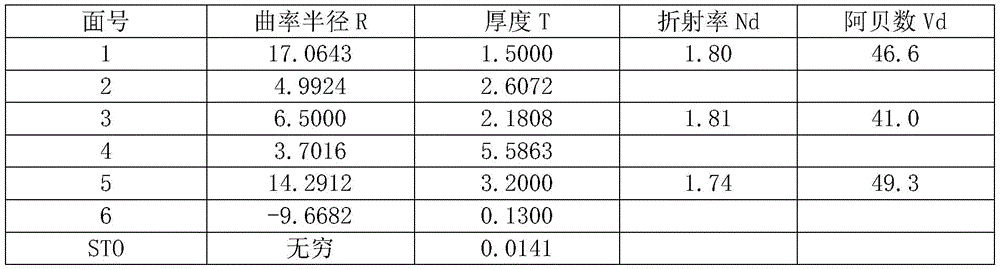

The present embodiment adopts six lenses as an example, and by reasonably distributing the focal power and the surface type of each lens, the central thickness of each lens and the air space between each lens, the lens has at least one beneficial effect of miniaturization, aberration balance, low sensitivity, high pixel, low cost, long back focus, good temperature performance and the like. Each aspherical surface type Z is defined by the following formula:

wherein Z is the distance rise from the vertex of the aspheric surface when the aspheric surface is at the position with the height of H along the optical axis direction; c is the paraxial curvature of the aspheric surface, c being 1/R (i.e., paraxial curvature c is the inverse of radius of curvature R in table 1 above); k is the conic coefficient conc; A. b, C, D, E are all high order term coefficients. Table 2 below shows conic coefficients k and high-order term coefficients A, B, C, D and E of the aspherical lens surfaces S3, S4, S5, S6, and S11 usable in example 1.
TABLE 2
| Flour mark | K | A | B | C | D | E |
| 3 | -1.0118 | 4.0232E-04 | -3.52E-05 | 9.29E-07 | -1.15E-07 | 1.92E-09 |
| 4 | -0.9914 | 2.1622E-03 | -3.4690E-05 | -4.6042E-06 | -4.5633E-07 | 2.1895E-08 |
| 5 | 2.7259 | 2.7601E-04 | 2.3606E-05 | -8.9983E-07 | 6.3617E-08 | 3.4559E-10 |
| 6 | -8.8025 | -7.6491E-04 | 3.3367E-05 | 3.7240E-06 | -3.7230E-07 | 1.4745E-08 |
| 11 | -0.2369 | 1.3997E-03 | -7.1431E-05 | 1.3586E-05 | -9.9700E-07 | 2.8015E-08 |
Table 3 below gives an optical back focus BFL of the optical lens of embodiment 1 (i.e., an on-axis distance from the center of the image-side surface S11 of the last lens sixth lens L6 to the imaging surface S16), a full-group focal length value F of the optical lens, an optical total length TTL of the optical lens (i.e., an on-axis distance from the center of the object-side surface S1 of the first lens L1 to the imaging surface S16), a maximum field angle FOV of the optical lens, a maximum clear aperture D of the object-side surface S1 of the first lens L1 corresponding to the maximum field angle of the optical lens, and an image height H corresponding to the maximum field angle of the optical lens.
TABLE 3
| Parameter(s) | BFL(mm) | F(mm) | TTL(mm) | FOV(°) | D(mm) | H(mm) |
| Numerical value | 7.082 | 4.941 | 30.013 | 120.6 | 14.972 | 9.196 |
In the present embodiment, D/H/FOV is 0.014 satisfied between the maximum field angle FOV of the optical lens, the maximum clear aperture D of the object-side surface S1 of the first lens L1 corresponding to the maximum field angle of the optical lens, and the image height H corresponding to the maximum field angle of the optical lens. The BFL/TTL is 0.236 between the optical back focus BFL of the optical lens and the optical total length TTL of the optical lens; and the total optical length TTL of the optical lens and the whole group focal length value F of the optical lens satisfy that the TTL/F is 6.074.
Example 2
An optical lens according to embodiment 2 of the present application is described below with reference to fig. 2. In this embodiment and the following embodiments, descriptions of parts similar to those of embodiment 1 will be omitted for the sake of brevity. Fig. 2 shows a schematic structural diagram of an optical lens according to embodiment 2 of the present application.
As shown in fig. 2, the optical lens includes, in order from the object side to the image side along the optical axis, a first lens L1, a second lens L2, a third lens L3, a fourth lens L4, a fifth lens L5, and a sixth lens L6.
The first lens L1 is a meniscus lens with negative power, with the object side S1 being convex and the image side S2 being concave.
The second lens L2 is a meniscus lens with negative power, with the object side S3 being convex and the image side S4 being concave. The second lens L2 is an aspherical lens, and both the object-side surface S3 and the image-side surface S4 are aspherical.
The third lens L3 is a biconvex lens with positive power, and has a convex object-side surface S5 and a convex image-side surface S6. The third lens element L3 is an aspherical lens, and both the object-side surface S5 and the image-side surface S6 are aspherical.
The fourth lens element L4 is a biconvex lens with positive power, and has a convex object-side surface S8 and a convex image-side surface S9. The fifth lens L5 is a biconcave lens with negative power, and has a concave object-side surface S9 and a concave image-side surface S10. The sixth lens element L6 is a biconvex lens with positive refractive power, and has a convex object-side surface S10 and a convex image-side surface S11. The sixth lens element L6 is an aspherical lens, and its image-side surface S11 is aspherical. Wherein the fourth lens L4, the fifth lens L5 and the sixth lens L6 are cemented to form a triple cemented lens.
Optionally, the optical lens may further include a filter L7 having an object-side surface S12 and an image-side surface S13, and a protective lens L8 having an object-side surface S14 and an image-side surface S15. Filter L7 can be used to correct for color deviations. The protective lens L8 may be used to protect the image sensing chip on the imaging plane IMA. Light from the object passes through each of the surfaces S1 to S15 in sequence and is finally imaged on the imaging plane IMA.
In the optical lens of the present embodiment, a stop STO may be provided between the third lens L3 and the fourth lens L4 to improve the imaging quality.
Table 4 below shows a radius of curvature R, a thickness T, a refractive index Nd, and an abbe number Vd of each lens of the optical lens of example 2, where the radius of curvature R and the thickness T are both in units of millimeters (mm). Table 5 below shows cone coefficients k and high-order term coefficients A, B, C, D and E that can be used for the aspherical lens surfaces S3, S4, S5, S6, and S11 in example 2. Table 6 below gives an optical back focus BFL of the optical lens of example 2 (i.e., an on-axis distance from the center of the image-side surface S11 of the last lens sixth lens L6 to the imaging surface S16), a full-group focal length value F of the optical lens, an optical total length TTL of the optical lens (i.e., an on-axis distance from the center of the object-side surface S1 of the first lens L1 to the imaging surface S16), a maximum field angle FOV of the optical lens, a maximum clear aperture D of the object-side surface S1 of the first lens L1 corresponding to the maximum field angle of the optical lens, and an image height H corresponding to the maximum field angle of the optical lens.
TABLE 4


TABLE 5
| Flour mark | K | A | B | C | D | E |
| 3 | -1.0118 | 4.02E-04 | -3.52E-05 | 9.29E-07 | -1.15E-07 | 1.82E-09 |
| 4 | -0.9914 | 2.16E-03 | -3.47E-05 | -4.60E-06 | -4.56E-07 | 2.69E-08 |
| 5 | 6.4835 | -4.07E-05 | 6.76E-05 | -9.86E-06 | 7.38E-07 | -2.29E-08 |
| 6 | -8.8025 | 1.35E-04 | -2.68E-05 | 1.77E-05 | -1.86E-06 | 7.75E-08 |
| 11 | 0.4949 | 1.33E-03 | -6.90E-05 | 1.36E-05 | -1.17E-06 | 3.10E-08 |
TABLE 6
| Parameter(s) | BFL(mm) | F(mm) | TTL(mm) | FOV(°) | D(mm) | H(mm) |
| Numerical value | 7.026 | 4.881 | 30.373 | 120.2 | 14.756 | 8.978 |
In the present embodiment, D/H/FOV is 0.014 satisfied between the maximum field angle FOV of the optical lens, the maximum clear aperture D of the object-side surface S1 of the first lens L1 corresponding to the maximum field angle of the optical lens, and the image height H corresponding to the maximum field angle of the optical lens. The BFL/TTL is 0.231 between the optical back focus BFL of the optical lens and the optical total length TTL of the optical lens; and the total optical length TTL of the optical lens and the whole group focal length value F of the optical lens satisfy that the TTL/F is 6.222.
Example 3
An optical lens according to embodiment 3 of the present application is described below with reference to fig. 3. In this embodiment and the following embodiments, descriptions of parts similar to those of embodiment 1 will be omitted for the sake of brevity. Fig. 3 shows a schematic structural diagram of an optical lens according to embodiment 3 of the present application.
As shown in fig. 3, the optical lens includes, in order from the object side to the image side along the optical axis, a first lens L1, a second lens L2, a third lens L3, a fourth lens L4, a fifth lens L5, and a sixth lens L6.
The first lens L1 is a meniscus lens with negative power, with the object side S1 being convex and the image side S2 being concave.
The second lens L2 is a meniscus lens with negative power, with the object side S3 being convex and the image side S4 being concave. The second lens L2 is an aspherical lens, and both the object-side surface S3 and the image-side surface S4 are aspherical.
The third lens L3 is a biconvex lens with positive power, and has a convex object-side surface S5 and a convex image-side surface S6. The third lens element L3 is an aspherical lens, and both the object-side surface S5 and the image-side surface S6 are aspherical.
The fourth lens element L4 is a biconvex lens with positive power, and has a convex object-side surface S8 and a convex image-side surface S9. The fifth lens L5 is a biconcave lens with negative power, and has a concave object-side surface S9 and a concave image-side surface S10. The sixth lens element L6 is a biconvex lens with positive refractive power, and has a convex object-side surface S10 and a convex image-side surface S11. The sixth lens element L6 is an aspherical lens, and its image-side surface S11 is aspherical. Wherein the fourth lens L4, the fifth lens L5 and the sixth lens L6 are cemented to form a triple cemented lens.
Optionally, the optical lens may further include a filter L7 having an object-side surface S12 and an image-side surface S13, and a protective lens L8 having an object-side surface S14 and an image-side surface S15. Filter L7 can be used to correct for color deviations. The protective lens L8 may be used to protect the image sensing chip on the imaging plane IMA. Light from the object passes through each of the surfaces S1 to S15 in sequence and is finally imaged on the imaging plane IMA.
In the optical lens of the present embodiment, a stop STO may be provided between the third lens L3 and the fourth lens L4 to improve the imaging quality.
Table 7 below shows a radius of curvature R, a thickness T, a refractive index Nd, and an abbe number Vd of each lens of the optical lens of example 3, where the radius of curvature R and the thickness T are both in units of millimeters (mm). Table 8 below shows cone coefficients k and high-order term coefficients A, B, C, D and E that can be used for the aspherical lens surfaces S3, S4, S5, S6, and S11 in example 3. Table 9 below gives an optical back focus BFL of the optical lens of example 3 (i.e., an on-axis distance from the center of the image-side surface S11 of the last lens sixth lens L6 to the imaging surface S16), a full-group focal length value F of the optical lens, an optical total length TTL of the optical lens (i.e., an on-axis distance from the center of the object-side surface S1 of the first lens L1 to the imaging surface S16), a maximum field angle FOV of the optical lens, a maximum clear aperture D of the object-side surface S1 of the first lens L1 corresponding to the maximum field angle of the optical lens, and an image height H corresponding to the maximum field angle of the optical lens.
TABLE 7
| Flour mark | Radius of curvature R | Thickness T | Refractive index Nd | |
| 1 | 17.0643 | 1.5000 | 1.80 | 46.57 |
| 2 | 4.9924 | 2.6072 | ||
| 3 | 6.5000 | 2.1808 | 1.80 | 46.57 |
| 4 | 3.7016 | 5.5775 | ||
| 5 | 14.2912 | 3.2000 | 1.74 | 49.34 |
| 6 | -9.6682 | 0.2000 | ||
| STO | All-round | 0.0141 | ||
| 8 | 8.6441 | 5.0745 | 1.52 | 64.21 |
| 9 | -8.6441 | 0.8000 | 1.81 | 22.69 |
| 10 | 8.6441 | 1.9125 | 1.62 | 63.42 |
| 11 | -11.5649 | 1.5664 | ||
| 12 | All-round | 0.5500 | 1.52 | 64.21 |
| 13 | All-round | 1.5131 | ||
| 14 | All-round | 0.4000 | 1.52 | 64.21 |
| 15 | All-round | 1.8837 | ||
| IMA | All-round |
TABLE 8
| Flour mark | K | A | B | C | D | E |
| 3 | -1.0118 | 4.02E-04 | -3.52E-05 | 9.29E-07 | -1.15E-07 | 1.82E-09 |
| 4 | -0.9914 | 2.16E-03 | -3.47E-05 | -4.60E-06 | -4.56E-07 | 2.59E-08 |
| 5 | 2.7259 | 2.76E-04 | 2.36E-05 | -9.00E-07 | 6.36E-08 | 3.26E-10 |
| 6 | -8.8025 | -7.65E-04 | 3.34E-05 | 3.72E-06 | -3.72E-07 | 1.87E-08 |
| 11 | -2.3134 | 1.05E-03 | -1.60E-06 | 1.11E-06 | 3.84E-08 | -5.38E-09 |
TABLE 9
| Parameter(s) | BFL(mm) | F(mm) | TTL(mm) | FOV(°) | D(mm) | H(mm) |
| Numerical value | 5.913 | 4.184 | 28.980 | 113.7 | 14.301 | 8.738 |
In the present embodiment, D/H/FOV is 0.014 satisfied between the maximum field angle FOV of the optical lens, the maximum clear aperture D of the object-side surface S1 of the first lens L1 corresponding to the maximum field angle of the optical lens, and the image height H corresponding to the maximum field angle of the optical lens. The BFL/TTL between the optical back focus BFL of the optical lens and the optical total length TTL of the optical lens is 0.204; and the total optical length TTL of the optical lens and the whole group focal length value F of the optical lens satisfy that the TTL/F is 6.926.
In summary, examples 1 to 3 each satisfy the relationship shown in table 10 below.
| Conditions/examples | 1 | 2 | 3 |
| D/H/FOV | 0.014 | 0.014 | 0.014 |
| BFL/TTL | 0.236 | 0.231 | 0.204 |
| TTL/F | 6.074 | 6.222 | 6.926 |
The above description is only a preferred embodiment of the application and is illustrative of the principles of the technology employed. It will be appreciated by a person skilled in the art that the scope of the invention as referred to in the present application is not limited to the embodiments with a specific combination of the above-mentioned features, but also covers other embodiments with any combination of the above-mentioned features or their equivalents without departing from the inventive concept. For example, the above features may be replaced with (but not limited to) features having similar functions disclosed in the present application.
Claims (17)
1. An optical lens includes six lenses having optical powers, namely a first lens, a second lens, a third lens, a fourth lens, a fifth lens and a sixth lens, wherein the first lens to the sixth lens are arranged in order from an object side to an image side along an optical axis,
it is characterized in that the preparation method is characterized in that,
the first lens has negative focal power, the object side surface of the first lens is a convex surface, and the image side surface of the first lens is a concave surface;
the second lens has negative focal power, the object side surface of the second lens is a convex surface, and the image side surface of the second lens is a concave surface;
the third lens has positive focal power, and both the object side surface and the image side surface of the third lens are convex surfaces;
the fourth lens has positive focal power, and both the object side surface and the image side surface of the fourth lens are convex surfaces;
the fifth lens has negative focal power, and both the object side surface and the image side surface of the fifth lens are concave; and
the sixth lens has positive focal power, and both the object side surface and the image side surface of the sixth lens are convex surfaces;
the optical lens satisfies: D/H/FOV is less than or equal to 0.025,
wherein the FOV is the maximum field angle of the optical lens;
d is the maximum light-passing aperture of the object-side surface of the first lens corresponding to the maximum field angle of the optical lens; and
and H is the image height corresponding to the maximum field angle of the optical lens.
2. An optical lens according to claim 1, wherein the fourth lens, the fifth lens and the sixth lens are cemented to form a cemented triplet.
3. An optical lens according to claim 1, characterized in that any one or all of the first to sixth lenses is a glass lens.
4. An optical lens according to claim 1, characterized in that at least one of the second lens, the third lens and the sixth lens is an aspherical mirror.
5. An optical lens according to any one of claims 1 to 4, characterized in that: the BFL/TTL is more than or equal to 0.15,
the BFL is the distance from the center of the image side surface of the sixth lens to the imaging surface of the optical lens on the optical axis; and
TTL is a distance on the optical axis from the center of the object-side surface of the first lens element to the imaging surface of the optical lens.
6. An optical lens barrel according to any one of claims 1 to 4, wherein a distance TTL between a center of an object side surface of the first lens and an imaging surface of the optical lens on the optical axis satisfies, for a whole group of focal length values F of the optical lens: TTL/F is less than or equal to 7.5.
7. An optical lens includes six lenses having optical powers, namely a first lens, a second lens, a third lens, a fourth lens, a fifth lens and a sixth lens, wherein the first lens to the sixth lens are arranged in order from an object side to an image side along an optical axis,
it is characterized in that the preparation method is characterized in that,
the first lens, the second lens and the fifth lens each have a negative optical power;
the third lens, the fourth lens and the sixth lens each have positive optical power; and
the fourth lens, the fifth lens and the sixth lens are cemented to form a triple cemented lens,
the distance TTL from the center of the object side surface of the first lens to the imaging surface of the optical lens on the optical axis and the whole group of focal length values F of the optical lens satisfy the following conditions: TTL/F is less than or equal to 7.5.
8. An optical lens barrel according to claim 7, wherein the object side surface of the first lens element is convex and the image side surface of the first lens element is concave.
9. An optical lens barrel according to claim 7, wherein the object side surface of the second lens element is convex and the image side surface is concave.
10. An optical lens barrel according to claim 7, wherein the object side surface and the image side surface of the third lens are convex.
11. An optical lens barrel according to claim 7, wherein the object side surface and the image side surface of the fourth lens are convex.
12. An optical lens barrel according to claim 7, wherein the fifth lens element has both object and image side surfaces that are concave.
13. An optical lens barrel according to claim 7, wherein the object-side surface and the image-side surface of the sixth lens element are convex.
14. An optical lens barrel according to any one of claims 7 to 13, wherein any one or all of the first to sixth lenses is a glass lens.
15. An optical lens according to any one of claims 7 to 13, characterized in that at least one of the second lens, the third lens and the sixth lens is an aspherical mirror.
16. An optical lens according to any one of claims 7 to 13, characterized in that: D/H/FOV is less than or equal to 0.025,
wherein the FOV is the maximum field angle of the optical lens;
d is the maximum light-passing aperture of the object-side surface of the first lens corresponding to the maximum field angle of the optical lens; and
and H is the image height corresponding to the maximum field angle of the optical lens.
17. An optical lens according to any one of claims 7 to 13, characterized in that: the BFL/TTL is more than or equal to 0.15,
the BFL is the distance from the center of the image side surface of the sixth lens to the imaging surface of the optical lens on the optical axis; and
TTL is a distance on the optical axis from the center of the object-side surface of the first lens element to the imaging surface of the optical lens.
Priority Applications (3)
| Application Number | Priority Date | Filing Date | Title |
|---|---|---|---|
| CN201810397943.0A CN110412721B (en) | 2018-04-28 | 2018-04-28 | Optical lens |
| PCT/CN2019/079983 WO2019205875A1 (en) | 2018-04-28 | 2019-03-28 | Optical lens |
| US17/081,042 US12061317B2 (en) | 2018-04-28 | 2020-10-27 | Optical lens assembly |
Applications Claiming Priority (1)
| Application Number | Priority Date | Filing Date | Title |
|---|---|---|---|
| CN201810397943.0A CN110412721B (en) | 2018-04-28 | 2018-04-28 | Optical lens |
Publications (2)
| Publication Number | Publication Date |
|---|---|
| CN110412721A CN110412721A (en) | 2019-11-05 |
| CN110412721B true CN110412721B (en) | 2021-01-08 |
Family
ID=68293748
Family Applications (1)
| Application Number | Title | Priority Date | Filing Date |
|---|---|---|---|
| CN201810397943.0A Active CN110412721B (en) | 2018-04-28 | 2018-04-28 | Optical lens |
Country Status (3)
| Country | Link |
|---|---|
| US (1) | US12061317B2 (en) |
| CN (1) | CN110412721B (en) |
| WO (1) | WO2019205875A1 (en) |
Families Citing this family (10)
| Publication number | Priority date | Publication date | Assignee | Title |
|---|---|---|---|---|
| CN114815148A (en) * | 2019-06-13 | 2022-07-29 | 玉晶光电(厦门)有限公司 | Optical imaging lens |
| JP6907433B1 (en) * | 2020-03-27 | 2021-07-21 | エスゼット ディージェイアイ テクノロジー カンパニー リミテッドSz Dji Technology Co.,Ltd | Lens system, image pickup device, and moving object |
| CN111812826B (en) * | 2020-06-12 | 2025-04-04 | 协益电子(苏州)有限公司 | A wide-angle lens |
| CN112433345B (en) * | 2020-12-07 | 2025-02-14 | 江西欧菲光学有限公司 | Optical lenses, camera modules, electronic devices and vehicles |
| CN114594568B (en) * | 2020-12-07 | 2024-06-25 | 宁波舜宇车载光学技术有限公司 | Optical lens and electronic device |
| CN112666685B (en) * | 2020-12-25 | 2023-05-16 | 玉晶光电(厦门)有限公司 | Optical imaging lens |
| CN112612118A (en) * | 2021-01-05 | 2021-04-06 | 协益电子(苏州)有限公司 | Vehicle-mounted optical lens |
| CN114089512B (en) * | 2022-01-24 | 2022-07-05 | 江西联益光学有限公司 | Optical lens and imaging apparatus |
| CN118465974B (en) * | 2024-06-04 | 2025-10-28 | 厦门力鼎光电股份有限公司 | An optical imaging lens |
| CN120353009B (en) * | 2025-06-25 | 2025-09-09 | 歌尔光学科技有限公司 | Imaging lens module and optical display device |
Citations (7)
| Publication number | Priority date | Publication date | Assignee | Title |
|---|---|---|---|---|
| JP2007108614A (en) * | 2005-10-17 | 2007-04-26 | Ricoh Co Ltd | Photography optical system, photography lens unit and camera |
| CN102369471A (en) * | 2009-04-03 | 2012-03-07 | 株式会社理光 | Wide angle lens and imaging device |
| CN107065147A (en) * | 2017-05-26 | 2017-08-18 | 东莞市宇瞳光学科技股份有限公司 | A kind of wide-angle super large aperture high-definition fixed-focus camera lens |
| CN107329241A (en) * | 2016-04-29 | 2017-11-07 | 信泰光学(深圳)有限公司 | Wide-angle lens |
| CN107436476A (en) * | 2017-06-22 | 2017-12-05 | 玉晶光电(厦门)有限公司 | Optical imaging lens |
| CN107577030A (en) * | 2016-07-05 | 2018-01-12 | 信泰光学(深圳)有限公司 | Wide-angle lens |
| CN108957709A (en) * | 2017-05-18 | 2018-12-07 | 信泰光学(深圳)有限公司 | Wide-angle lens |
Family Cites Families (7)
| Publication number | Priority date | Publication date | Assignee | Title |
|---|---|---|---|---|
| JP2006349920A (en) * | 2005-06-15 | 2006-12-28 | Ricoh Co Ltd | Imaging optical system, imaging lens unit, camera, and portable information terminal device |
| TW201037354A (en) * | 2009-04-15 | 2010-10-16 | Young Optics Inc | Fixed-focus lens |
| KR101917228B1 (en) * | 2011-08-17 | 2019-01-29 | 엘지이노텍 주식회사 | Imaging lens |
| JP2013073160A (en) * | 2011-09-29 | 2013-04-22 | Fujifilm Corp | Image pickup lens and image pickup apparatus |
| US9784956B2 (en) * | 2012-10-25 | 2017-10-10 | Young Optics Inc. | Wide-angle projection system |
| WO2014175038A1 (en) * | 2013-04-22 | 2014-10-30 | オリンパスメディカルシステムズ株式会社 | Wide-angle objective optical system |
| US10877251B2 (en) * | 2015-11-20 | 2020-12-29 | Sony Corporation | Imaging lens |
-
2018
- 2018-04-28 CN CN201810397943.0A patent/CN110412721B/en active Active
-
2019
- 2019-03-28 WO PCT/CN2019/079983 patent/WO2019205875A1/en not_active Ceased
-
2020
- 2020-10-27 US US17/081,042 patent/US12061317B2/en active Active
Patent Citations (7)
| Publication number | Priority date | Publication date | Assignee | Title |
|---|---|---|---|---|
| JP2007108614A (en) * | 2005-10-17 | 2007-04-26 | Ricoh Co Ltd | Photography optical system, photography lens unit and camera |
| CN102369471A (en) * | 2009-04-03 | 2012-03-07 | 株式会社理光 | Wide angle lens and imaging device |
| CN107329241A (en) * | 2016-04-29 | 2017-11-07 | 信泰光学(深圳)有限公司 | Wide-angle lens |
| CN107577030A (en) * | 2016-07-05 | 2018-01-12 | 信泰光学(深圳)有限公司 | Wide-angle lens |
| CN108957709A (en) * | 2017-05-18 | 2018-12-07 | 信泰光学(深圳)有限公司 | Wide-angle lens |
| CN107065147A (en) * | 2017-05-26 | 2017-08-18 | 东莞市宇瞳光学科技股份有限公司 | A kind of wide-angle super large aperture high-definition fixed-focus camera lens |
| CN107436476A (en) * | 2017-06-22 | 2017-12-05 | 玉晶光电(厦门)有限公司 | Optical imaging lens |
Also Published As
| Publication number | Publication date |
|---|---|
| CN110412721A (en) | 2019-11-05 |
| US20210063705A1 (en) | 2021-03-04 |
| WO2019205875A1 (en) | 2019-10-31 |
| US12061317B2 (en) | 2024-08-13 |
Similar Documents
| Publication | Publication Date | Title |
|---|---|---|
| CN110412721B (en) | Optical lens | |
| CN112180538B (en) | Optical lens and imaging apparatus | |
| CN110456475B (en) | Optical lens | |
| CN110542978B (en) | Optical lens | |
| CN112882200B (en) | Optical lens | |
| CN110412727B (en) | Optical lens | |
| CN110794552A (en) | Optical lens | |
| CN109581620B (en) | Optical lens | |
| CN110632736B (en) | Optical lens | |
| CN109960004B (en) | Optical lens | |
| CN111474673B (en) | Optical lens and imaging apparatus | |
| CN109491056B (en) | Optical lens and imaging apparatus | |
| CN109425959B (en) | Optical lens | |
| CN111830672B (en) | Optical lens and imaging apparatus | |
| CN110764223B (en) | Optical lens | |
| CN112014946B (en) | Optical lens and imaging apparatus | |
| CN111123471B (en) | Optical lens | |
| CN110501807B (en) | Optical lens | |
| CN109324397B (en) | Optical lens | |
| CN111352214B (en) | Optical lens and imaging apparatus | |
| CN109425957B (en) | Optical lens | |
| CN111221099B (en) | Optical lens and imaging apparatus | |
| CN110412730B (en) | Optical lens | |
| CN110794551B (en) | Optical lens | |
| CN110554475B (en) | Optical lens |
Legal Events
| Date | Code | Title | Description |
|---|---|---|---|
| PB01 | Publication | ||
| PB01 | Publication | ||
| SE01 | Entry into force of request for substantive examination | ||
| SE01 | Entry into force of request for substantive examination | ||
| GR01 | Patent grant | ||
| GR01 | Patent grant |