CN110403603B - A monitoring device for assisting epilepsy surgery - Google Patents
A monitoring device for assisting epilepsy surgery Download PDFInfo
- Publication number
- CN110403603B CN110403603B CN201910724498.9A CN201910724498A CN110403603B CN 110403603 B CN110403603 B CN 110403603B CN 201910724498 A CN201910724498 A CN 201910724498A CN 110403603 B CN110403603 B CN 110403603B
- Authority
- CN
- China
- Prior art keywords
- ring
- telescopic rod
- electric telescopic
- motor
- slide rail
- Prior art date
- Legal status (The legal status is an assumption and is not a legal conclusion. Google has not performed a legal analysis and makes no representation as to the accuracy of the status listed.)
- Active
Links
- 206010015037 epilepsy Diseases 0.000 title claims abstract description 22
- 238000012806 monitoring device Methods 0.000 title claims abstract description 12
- 238000001356 surgical procedure Methods 0.000 title claims abstract description 12
- 210000000078 claw Anatomy 0.000 claims abstract description 27
- 230000001037 epileptic effect Effects 0.000 claims abstract description 6
- 238000001514 detection method Methods 0.000 claims description 4
- 210000004556 brain Anatomy 0.000 abstract description 11
- 238000005259 measurement Methods 0.000 abstract description 9
- 238000012544 monitoring process Methods 0.000 abstract description 6
- 230000009286 beneficial effect Effects 0.000 abstract description 2
- 238000000034 method Methods 0.000 description 9
- 206010010904 Convulsion Diseases 0.000 description 5
- 238000012549 training Methods 0.000 description 5
- 230000002397 epileptogenic effect Effects 0.000 description 4
- 210000004761 scalp Anatomy 0.000 description 3
- 208000012902 Nervous system disease Diseases 0.000 description 2
- 206010061334 Partial seizures Diseases 0.000 description 2
- 230000002159 abnormal effect Effects 0.000 description 2
- 230000001684 chronic effect Effects 0.000 description 2
- 238000010586 diagram Methods 0.000 description 2
- 201000010099 disease Diseases 0.000 description 2
- 208000037265 diseases, disorders, signs and symptoms Diseases 0.000 description 2
- 201000007186 focal epilepsy Diseases 0.000 description 2
- 210000003128 head Anatomy 0.000 description 2
- 238000009434 installation Methods 0.000 description 2
- 230000003902 lesion Effects 0.000 description 2
- 230000001537 neural effect Effects 0.000 description 2
- 208000037158 Partial Epilepsies Diseases 0.000 description 1
- 230000005856 abnormality Effects 0.000 description 1
- 230000002411 adverse Effects 0.000 description 1
- 239000001961 anticonvulsive agent Substances 0.000 description 1
- 239000003086 colorant Substances 0.000 description 1
- 238000007796 conventional method Methods 0.000 description 1
- 230000000694 effects Effects 0.000 description 1
- 238000005516 engineering process Methods 0.000 description 1
- 230000001709 ictal effect Effects 0.000 description 1
- 239000000463 material Substances 0.000 description 1
- 230000002093 peripheral effect Effects 0.000 description 1
- 238000006467 substitution reaction Methods 0.000 description 1
- 208000024891 symptom Diseases 0.000 description 1
- 238000012360 testing method Methods 0.000 description 1
- 238000011179 visual inspection Methods 0.000 description 1
Images


Classifications
-
- A—HUMAN NECESSITIES
- A61—MEDICAL OR VETERINARY SCIENCE; HYGIENE
- A61B—DIAGNOSIS; SURGERY; IDENTIFICATION
- A61B5/00—Measuring for diagnostic purposes; Identification of persons
- A61B5/24—Detecting, measuring or recording bioelectric or biomagnetic signals of the body or parts thereof
- A61B5/316—Modalities, i.e. specific diagnostic methods
- A61B5/369—Electroencephalography [EEG]
-
- A—HUMAN NECESSITIES
- A61—MEDICAL OR VETERINARY SCIENCE; HYGIENE
- A61B—DIAGNOSIS; SURGERY; IDENTIFICATION
- A61B34/00—Computer-aided surgery; Manipulators or robots specially adapted for use in surgery
- A61B34/10—Computer-aided planning, simulation or modelling of surgical operations
-
- A—HUMAN NECESSITIES
- A61—MEDICAL OR VETERINARY SCIENCE; HYGIENE
- A61B—DIAGNOSIS; SURGERY; IDENTIFICATION
- A61B5/00—Measuring for diagnostic purposes; Identification of persons
- A61B5/40—Detecting, measuring or recording for evaluating the nervous system
- A61B5/4076—Diagnosing or monitoring particular conditions of the nervous system
- A61B5/4094—Diagnosing or monitoring seizure diseases, e.g. epilepsy
-
- A—HUMAN NECESSITIES
- A61—MEDICAL OR VETERINARY SCIENCE; HYGIENE
- A61B—DIAGNOSIS; SURGERY; IDENTIFICATION
- A61B34/00—Computer-aided surgery; Manipulators or robots specially adapted for use in surgery
- A61B34/10—Computer-aided planning, simulation or modelling of surgical operations
- A61B2034/107—Visualisation of planned trajectories or target regions
-
- Y—GENERAL TAGGING OF NEW TECHNOLOGICAL DEVELOPMENTS; GENERAL TAGGING OF CROSS-SECTIONAL TECHNOLOGIES SPANNING OVER SEVERAL SECTIONS OF THE IPC; TECHNICAL SUBJECTS COVERED BY FORMER USPC CROSS-REFERENCE ART COLLECTIONS [XRACs] AND DIGESTS
- Y02—TECHNOLOGIES OR APPLICATIONS FOR MITIGATION OR ADAPTATION AGAINST CLIMATE CHANGE
- Y02A—TECHNOLOGIES FOR ADAPTATION TO CLIMATE CHANGE
- Y02A90/00—Technologies having an indirect contribution to adaptation to climate change
- Y02A90/30—Assessment of water resources
Landscapes
- Health & Medical Sciences (AREA)
- Life Sciences & Earth Sciences (AREA)
- Surgery (AREA)
- Engineering & Computer Science (AREA)
- Animal Behavior & Ethology (AREA)
- Veterinary Medicine (AREA)
- Biomedical Technology (AREA)
- Heart & Thoracic Surgery (AREA)
- Medical Informatics (AREA)
- Molecular Biology (AREA)
- Neurology (AREA)
- General Health & Medical Sciences (AREA)
- Public Health (AREA)
- Neurosurgery (AREA)
- Physics & Mathematics (AREA)
- Biophysics (AREA)
- Pathology (AREA)
- Robotics (AREA)
- Nuclear Medicine, Radiotherapy & Molecular Imaging (AREA)
- Physiology (AREA)
- Psychiatry (AREA)
- Psychology (AREA)
- Measurement And Recording Of Electrical Phenomena And Electrical Characteristics Of The Living Body (AREA)
Abstract
本发明提供了一种用于辅助癫痫手术的监测设备,设备包括支撑环、固定环和滑动环,固定环前后方向设置、两端与支撑环固定,所述滑动环左右方向设置,可相对于固定环滑动,滑动环与支撑环通过铰接部可转动连接,滑动环上可移动的设置有测量爪。与现有技术相比,本发明具有以下有益效果:能够准确的识别癫痫病灶区和非病灶区,便于医生规划大脑的手术区域。通过测量爪移动和伸缩,可以变换监测位置,以及缩小监测范围,可使测量更加准确、可靠。
The invention provides a monitoring device for assisting epilepsy surgery. The device includes a support ring, a fixed ring and a sliding ring. The fixed ring slides, the sliding ring and the support ring are rotatably connected through a hinge, and the sliding ring is movably provided with measuring claws. Compared with the prior art, the present invention has the following beneficial effects: it can accurately identify epileptic focus areas and non-focus areas, and is convenient for doctors to plan brain operation areas. By moving and stretching the measuring claws, the monitoring position can be changed and the monitoring range can be narrowed, so that the measurement can be more accurate and reliable.
Description
技术领域technical field
本发明属于医疗仪器领域,具体涉及一种用于辅助癫痫手术的监测设备。The invention belongs to the field of medical instruments, and in particular relates to a monitoring device for assisting epilepsy operations.
背景技术Background technique
脑电信号(EEG)可用于识别不同疾病状态下的人脑。尽管如此,由于EEG信号的非静止性质,仅仅通过视觉检查来检测EEG的微妙和重要差异是困难的。Electroencephalogram signals (EEG) can be used to identify the human brain in different disease states. Nonetheless, detecting subtle and important differences in EEG by visual inspection alone is difficult due to the non-stationary nature of the EEG signal.
具体而言,为了在部分性癫痫的情况下找到医学治疗的致痫灶,需要能够准确且自动地检测和区分病灶区和非病灶区的EEG信号的智能系统。这将有助于临床医生在手术前找到癫痫病灶。Specifically, in order to find the epileptogenic focus of medical treatment in the case of partial epilepsy, an intelligent system capable of accurately and automatically detecting and distinguishing EEG signals of focal and non-focal regions is required. This will help clinicians find epileptic foci before surgery.
癫痫是由于异常和过度的大脑神经元活动引起的慢性神经系统疾病,其中EEG信号是评估癫痫最常用和最有效的临床技术。Epilepsy is a chronic neurological disorder caused by abnormal and excessive neuronal activity in the brain, where EEG signals are the most commonly used and effective clinical technique for evaluating epilepsy.
病灶性癫痫是癫痫的一种形式,其中癫痫的发作发生在大脑的有限区域。病灶性脑电图作为一种脑电图信号,它是从检测到第一次发作性脑电图(癫痫发作)变化的大脑区域记录的。另一方面,非病灶性脑电图被称为从癫痫发作未涉及的脑区记录的另一种脑电图信号。Focal epilepsy is a form of epilepsy in which seizures occur in a limited area of the brain. Focal EEG is an EEG signal that is recorded from the brain region where the first ictal EEG (seizure) change was detected. Nonfocal EEG, on the other hand, is referred to as another EEG signal recorded from a brain region not involved in the seizure.
癫痫患者通常对抗癫痫药物反应不佳,因此需要手术切除导致癫痫的大脑部分以消除这种疾病。导致癫痫发作的大脑部分被称为致癫痫病灶。在手术前定位致癫痫病灶的常规方法是基于临床程序的人工脑电图检查,该检查是主观的、经验的、费力的和乏味的。People with epilepsy often do not respond well to antiepileptic drugs, so surgical removal of the part of the brain that causes the seizure is required to eliminate the disease. The part of the brain that causes a seizure is called an epileptogenic focus. The conventional method for locating epileptogenic foci before surgery is manual EEG examination based on clinical procedures, which is subjective, empirical, laborious, and tedious.
因此,有必要开发一种自动和准确的技术,用于病灶性和非病灶性EEG信号的分类,这可以帮助医生识别致癫痫病灶,以便规划大脑的手术区域。Therefore, it is necessary to develop an automatic and accurate technique for the classification of focal and nonfocal EEG signals, which can help physicians identify epileptogenic foci for planning surgical regions of the brain.
发明内容Contents of the invention
鉴于上述技术问题,本发明提供了一种用于辅助癫痫手术的监测设备,旨在能够识别癫痫的病灶区和非病灶区。In view of the above technical problems, the present invention provides a monitoring device for assisting epilepsy surgery, aiming at being able to identify epilepsy focal areas and non-lesional areas.
为解决上述技术问题,本发明的技术方案如下:In order to solve the problems of the technologies described above, the technical solution of the present invention is as follows:
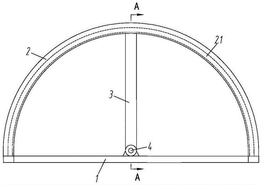
一种用于辅助癫痫手术的监测设备,所述设备包括支撑环1、固定环2和滑动环3,所述固定环2前后方向设置、两端与支撑环1固定,所述滑动环3左右方向设置,可相对于固定环2滑动,滑动环3与支撑环1通过铰接部4可转动连接,所述滑动环3上可移动的设置有测量爪5。A monitoring device for assisting epilepsy surgery, the device includes a support ring 1, a
进一步地,所述测量爪5上设置有多个测量电极5.5。Further, the
进一步地,所述固定环2上设置第一滑轨2.1,所述第一滑轨2.1呈“∏”型,所述第一滑轨2.1上设置第一齿条2.2,所述滑动环3上设置第一连接块3.2,所述第一连接块3.2上固定有第一电机3.3,所述第一电机3.3的输出轴连接有第一齿轮3.4,所述第一齿轮3.4与第一齿条2.2啮合。Further, the
进一步地,所述滑动环3上设置第二滑轨3.1,所述第二滑轨3.1呈“∏”型,所述滑动环3的下侧设置有第二齿条3.5,所述测量爪5上设置有滑块5.1,所述滑块5.1可在第二滑轨3.1内滑动,所述滑块5.1的下侧固定有第一电动伸缩杆5.2,所述第一电动伸缩杆5.2的端部铰接第二电动伸缩杆5.3的一端,所述第二电动伸缩杆5.3与支撑板5.4铰接,支撑板5.4通过第三电动伸缩杆5.11连接中心电极5.5,所述第二电动伸缩杆5.3的另一端也设置有电极5.5。Further, a second slide rail 3.1 is provided on the slide ring 3, and the second slide rail 3.1 is in the shape of "∏", a second rack 3.5 is provided on the underside of the slide ring 3, and the measuring claw 5 A slider 5.1 is arranged on the top, and the slider 5.1 can slide in the second slide rail 3.1. The first electric telescopic rod 5.2 is fixed on the lower side of the slider 5.1, and the end of the first electric telescopic rod 5.2 One end of the second electric telescopic rod 5.3 is hinged, the second electric telescopic rod 5.3 is hinged with the support plate 5.4, the support plate 5.4 is connected to the center electrode 5.5 through the third electric telescopic rod 5.11, the other end of the second electric telescopic rod 5.3 An electrode 5.5 is also provided.
进一步地,所述滑块5.1上固定有第二电机5.6,所述第二电机5.6的输出轴连接第二齿轮5.7,所述第二齿轮5.7与第二齿条3.5啮合,所述滑块5.1可支撑在第二滑轨3.1内滑动。Further, the slider 5.1 is fixed with a second motor 5.6, the output shaft of the second motor 5.6 is connected to the second gear 5.7, and the second gear 5.7 meshes with the second rack 3.5, and the slider 5.1 It can be supported to slide in the second slide rail 3.1.
进一步地,所述电极5.5之间设置有连接线5.8。Further, connecting wires 5.8 are arranged between the electrodes 5.5.
进一步地,所述第一齿条2.2设置在第一滑轨2.1的内部上侧,所述第一齿条2.2设置两条,所述第一电机3.3设置在第一滑轨2.1的内腔中,所述第一齿轮3.4也对应设置两个。Further, the first rack 2.2 is arranged on the inner upper side of the first slide rail 2.1, two first racks 2.2 are provided, and the first motor 3.3 is arranged in the inner cavity of the first slide rail 2.1 , two first gears 3.4 are correspondingly provided.
进一步地,所述第二齿条3.5设置两条,所述第二电机5.6为双轴输出电机,所述第二齿轮5.7对应设置两个。Further, there are two second racks 3.5, the second motor 5.6 is a dual-shaft output motor, and two second gears 5.7 are correspondingly provided.
与现有技术相比,本发明具有以下有益效果:能够准确的识别癫痫病灶区和非病灶区,便于医生规划大脑的手术区域。通过测量爪移动和伸缩,可以变换监测位置,以及缩小监测范围,可使测量更加准确、可靠。Compared with the prior art, the present invention has the following beneficial effects: it can accurately identify epileptic focus areas and non-focus areas, and is convenient for doctors to plan brain operation areas. By moving and stretching the measuring claws, the monitoring position can be changed and the monitoring range can be narrowed, so that the measurement can be more accurate and reliable.
附图说明Description of drawings
图1本发明头套结构示意图;Fig. 1 structural representation of headgear of the present invention;
图2本发明图1A-A向头套结构示意图;Fig. 2 is a schematic structural diagram of the headgear shown in Fig. 1A-A of the present invention;
图3本发明局部放大图;Figure 3 is a partial enlarged view of the present invention;
图4本发明局部放大图;Figure 4 is a partial enlarged view of the present invention;
图5本发明测量爪结构示意图;Fig. 5 is a structural schematic diagram of the measuring claw of the present invention;
图6本发明测量爪仰视图;Figure 6 is a bottom view of the measuring claw of the present invention;
图7本发明测量区域的实施例;The embodiment of Fig. 7 measurement area of the present invention;
图中支撑环1、固定环2、第一滑轨2.1、第一齿条2.2、滑动环3、第二滑轨3.1、第一连接块3.2、第一电机3.3、第一齿轮3.4、第二齿条3.5、铰接部4、测量爪5、滑块5.1、第一电动伸缩杆5.2、第二电动伸缩杆5.3、支撑板5.4、电极5.5、第二电机5.6、第二齿轮5.7、连接线5.8、第三电动伸缩杆5.11。In the figure, support ring 1,
具体实施方式Detailed ways
下面将结合本发明实施例中的附图,对本发明实施例中的技术方案进行清楚、完整地描述,显然,所描述的实施例仅仅是本发明一部分实施例,而不是全部的实施例。基于本发明中的实施例,本领域普通技术人员在没有做出创造性劳动前提下所获得的所有其他实施例,都属于本发明保护的范围。The following will clearly and completely describe the technical solutions in the embodiments of the present invention with reference to the accompanying drawings in the embodiments of the present invention. Obviously, the described embodiments are only some, not all, embodiments of the present invention. Based on the embodiments of the present invention, all other embodiments obtained by persons of ordinary skill in the art without making creative efforts belong to the protection scope of the present invention.
在本发明的描述中,需要理解的是,术语“中心”、“长度”、“宽度”、“厚度”、“上”、“下”、“前”、“后”、“左”、“右”、“竖直”、“水平”、“顶”、“底”“内”、“外”、“轴向”、“周向”等指示的方位或位置关系为基于附图所示的方位或位置关系,仅是为了便于描述本发明和简化描述,而不是指示或暗示所指的装置或元件必须具有特定的方位、以特定的方位构造和操作,因此不能理解为对本发明的限制。In describing the present invention, it should be understood that the terms "center", "length", "width", "thickness", "upper", "lower", "front", "rear", "left", " The orientations or positional relationships indicated by "right", "vertical", "horizontal", "top", "bottom", "inner", "outer", "axial", "circumferential" are based on those shown in the drawings Orientation or positional relationship is only for the convenience of describing the present invention and simplifying the description, and does not indicate or imply that the referred device or element must have a specific orientation, be constructed and operated in a specific orientation, and thus should not be construed as a limitation of the present invention.
在本发明中,除非另有明确的规定和限定,术语“设置”、“安装”、“相连”、“连接”、“固定”等术语应做广义理解,例如,可以是固定连接,也可以是可拆卸连接;可以是机械连接;可以是直接相连,也可以通过中间媒介间接相连。对于本领域的普通技术人员而言,可以根据具体情况理解上述术语在本发明中的具体含义。In the present invention, terms such as "installation", "installation", "connection", "connection" and "fixation" should be interpreted in a broad sense, for example, it may be a fixed connection or It is a detachable connection; it may be a mechanical connection; it may be a direct connection or an indirect connection through an intermediary. Those of ordinary skill in the art can understand the specific meanings of the above terms in the present invention according to specific situations.
此外,术语“第一”、“第二”等仅用于描述目的,而不能理解为指示或暗示相对重要性或者隐含指明所指示的技术特征的数量。由此,限定有“第一”、“第二”的特征可以明示或者隐含地包括一个或者更多个该特征。In addition, the terms "first", "second", etc. are used for descriptive purposes only, and should not be understood as indicating or implying relative importance or implicitly specifying the quantity of the indicated technical features. Thus, a feature defined as "first" and "second" may explicitly or implicitly include one or more of these features.
癫痫是由于异常和过度的大脑神经元活动引起的慢性神经系统疾病,其中EEG信号是评估癫痫最常用和最有效的临床技术。Epilepsy is a chronic neurological disorder caused by abnormal and excessive neuronal activity in the brain, where EEG signals are the most commonly used and effective clinical technique for evaluating epilepsy.
如图1-3所示,本发明提供了一种用于辅助癫痫手术的监测设备,所述设备包括支撑环1、固定环2和滑动环3。如图1所示,所述固定环2前后方向设置、两端与支撑环1固定。如图1、2所示,所述滑动环3左右方向设置,可相对于固定环2滑动,滑动环3与支撑环1通过铰接部4可转动连接,所述滑动环3上可移动的设置有测量爪5。As shown in FIGS. 1-3 , the present invention provides a monitoring device for assisting epilepsy surgery. The device includes a support ring 1 , a
如图4所示,所述测量爪5上设置有多个测量电极5.5。As shown in FIG. 4 , a plurality of measuring electrodes 5.5 are arranged on the
所述固定环2上设置第一滑轨2.1,所述第一滑轨2.1呈“∏”型,所述第一滑轨2.1上设置第一齿条2.2,所述滑动环3上设置第一连接块3.2,所述第一连接块3.2上固定有第一电机3.3,所述第一电机3.3的输出轴连接有第一齿轮3.4,所述第一齿轮3.4与第一齿条2.2啮合。The first slide rail 2.1 is set on the
所述滑动环3上设置第二滑轨3.1,所述第二滑轨3.1呈“∏”型,所述滑动环3的下侧设置有第二齿条3.5,所述测量爪5上设置有滑块5.1,所述滑块5.1可在第二滑轨3.1内滑动,所述滑块5.1的下侧固定有第一电动伸缩杆5.2,所述第一电动伸缩杆5.2的端部铰接第二电动伸缩杆5.3的一端,所述第二电动伸缩杆5.3与支撑板5.4铰接,支撑板5.4通过第三电动伸缩杆5.11连接中心电极5.5(该电极为如图6、7中所示的处于中心处的电极),所述第二电动伸缩杆5.3的另一端也设置有电极5.5。The second slide rail 3.1 is arranged on the slide ring 3, and the second slide rail 3.1 is in the shape of "∏", the second rack 3.5 is provided on the lower side of the slide ring 3, and the
所述滑块5.1上固定有第二电机5.6,所述第二电机5.6的输出轴连接第二齿轮5.7,所述第二齿轮5.7与第二齿条3.5啮合,所述滑块5.1可支撑在第二滑轨3.1内滑动。A second motor 5.6 is fixed on the slider 5.1, the output shaft of the second motor 5.6 is connected to a second gear 5.7, and the second gear 5.7 meshes with the second rack 3.5, and the slider 5.1 can be supported on The second sliding rail 3.1 slides inside.
所述电极5.5之间设置有连接线5.8。Connecting wires 5.8 are arranged between the electrodes 5.5.
所述第一齿条2.2设置在第一滑轨2.1的内部上侧,所述第一齿条2.2设置两条,所述第一电机3.3设置在第一滑轨2.1的内腔中,所述第一电机3.3为双轴输出电机,所述第一齿轮3.4也对应设置两个。The first rack 2.2 is arranged on the inner upper side of the first slide rail 2.1, two first racks 2.2 are provided, the first motor 3.3 is arranged in the inner cavity of the first slide rail 2.1, the The first motor 3.3 is a dual-shaft output motor, and two first gears 3.4 are correspondingly provided.
所述第二齿条3.5设置两条,所述第二电机5.6为双轴输出电机,所述第二齿轮5.7对应设置两个。There are two second racks 3.5, the second motor 5.6 is a dual-axis output motor, and two second gears 5.7 are correspondingly provided.
本发明的用于辅助癫痫手术的监测设备还连接有控制器和显示器,所述控制器包括存储装置和处理器,所述存储装置存储有标准脑电图信号模板,所述处理器用于控制监测装置的运作,包括采集阶段的控制和测量阶段的控制。所述显示器生成头部显示图像,并在测量后将疑似病灶区域在图像上使用不同的颜色进行标记。The monitoring equipment for assisting epilepsy surgery of the present invention is also connected with a controller and a display, the controller includes a storage device and a processor, the storage device stores a standard EEG signal template, and the processor is used to control the monitoring The operation of the device, including the control of the acquisition phase and the control of the measurement phase. The monitor generates a head display image, and after the measurement, the suspected lesion area is marked on the image with different colors.
本发明监测设备的每个电极5.5上还可设置有标记笔,用于标记检测异常(疑似病灶区域)电极5.5处的区域,本发明中的标记材料易于进行擦除,且不会对头部产生任何不利的影响。Each electrode 5.5 of the monitoring device of the present invention can also be provided with a marking pen, which is used to mark the area at the electrode 5.5 for detecting abnormalities (suspected focus areas). The marking material in the present invention is easy to erase and will not damage the head. produce any adverse effects.
图7表示的是本发明测量爪5实际测量的几个区域,本发明的区域不仅限于图7所示的。FIG. 7 shows several areas actually measured by the measuring
本发明的具体实施操作方式如下:The concrete implementation mode of operation of the present invention is as follows:
首先生成标准脑电图信号模板,该生成方法可通过以下两种方式:Firstly, a standard EEG signal template is generated, which can be generated in the following two ways:
第一种,进行正常脑电图信号的采集,通过本发明的装置采集一定数量的正常人脑电图信号,通过训练的方式生成标准脑电图信号模板。采集脑电图信号的数量根据实际需要的判断精度确定,理论上是采集的数量越多,后续训练的模板越能接近理想的正常值;The first one is to collect normal EEG signals, collect a certain number of normal EEG signals through the device of the present invention, and generate standard EEG signal templates through training. The number of collected EEG signals is determined according to the judgment accuracy of actual needs. In theory, the more the number of collected EEG signals, the closer the template for subsequent training can be to the ideal normal value;
第二种,从数据库中读取存储的正常人的脑电信号图,如第一种方法,也是通过训练的方式生成标准脑电图信号模板。第二种方法的优势在于能够通过数据库种存储的癫痫病人的脑电信号进行测试,实际检测训练后的模板的适应度,适应度的意思就是模板能够检测出癫痫脑电信号的准确度。如果训练后的模板检测的准确度比较低,可以重新进行训练。The second method is to read the stored normal person's EEG signal map from the database. Like the first method, a standard EEG signal template is also generated through training. The advantage of the second method is that it can test the EEG signals of epilepsy patients stored in the database, and actually detect the fitness of the trained template. The fitness means the accuracy with which the template can detect epileptic EEG signals. If the accuracy of template detection after training is relatively low, training can be performed again.
在进行实际测量时,步骤如下:When making the actual measurement, the steps are as follows:
步骤1,移动测量爪5的位置,通过移动滑动环3和滑块5.1调节测量爪5的位置;Step 1, move the position of the measuring
步骤2,控制器驱动第一电动伸缩杆5.2伸长,使中心处的电极5.5抵接头皮(中心处的电极5.5设置成可伸缩状态,优选的为设置第三电动伸缩杆5.11);
步骤3,控制第二电动伸缩杆5.3的伸长或缩回,调节测量区域,在第一电动伸缩杆5.3动作完成后,再控制第一电动伸缩杆5.2缩回,使如图6、7所示的周边的电极5.5能够与头皮贴合,由于中心处的中心电极5.5是可伸缩的(通过控制器控制第三电动伸缩杆5.11),所以此时中心处的电极5.5依旧能够抵接在头皮;Step 3, control the extension or retraction of the second electric telescopic rod 5.3, adjust the measurement area, and then control the retraction of the first electric telescopic rod 5.2 after the action of the first electric telescopic rod 5.3 is completed, so that as shown in Figures 6 and 7 The peripheral electrode 5.5 shown can be attached to the scalp. Since the central electrode 5.5 at the center is scalable (the third electric telescopic rod 5.11 is controlled by the controller), the electrode 5.5 at the center can still be in contact with the scalp at this time. ;
步骤4,模板匹配,将测量的数据与标准脑电图信号模板进行比较,判断判断癫痫病灶区域;Step 4, template matching, comparing the measured data with the standard EEG signal template, and judging the epilepsy focus area;
步骤5,显示,显示器将疑似病灶区域在虚拟头部图像上标记并显示。
步骤6,重复步骤1-5。Step 6, repeat steps 1-5.
通过移动滑动环3和滑块5.1可以调节测量爪5的位置,实现测量爪5位置的任意调节,在测量爪5移动到疑似癫痫病灶区域之后,可在这个区域内移动到任意位置,同时通过第一电动伸缩杆5.2和第二电动伸缩杆5.3调节测量爪5上的电极5.5的张开的大小,即调节测量爪5上电极5.5之间的距离,实现单位区域内电极数量的增加,提高检测精度,能够对癫痫病灶实现准确定位。本发明提供了一种自动、准确的技术,基于检测设备用于病灶性和非病灶性EEG信号的分类。The position of the measuring
本发明中的控制器用于控制各部件的运作,具体为控制滑动环3、第一电机3.3、测量爪5、第一电动伸缩杆5.2、第二电动伸缩杆5.3、电极5.5、第二电机5.6、第三电动伸缩杆5.11等,具体的控制通过控制器能够协调各部件,实现快速、高效、准确的测量。The controller in the present invention is used to control the operation of each component, specifically to control the slip ring 3, the first motor 3.3, the measuring
本发明监测设备通过调节控制器的测量周期(即通过调节控制器控制滑动环3、滑块5.1、第一电动伸缩杆5.2和第二电动伸缩杆5.3的运作时间)以适应不同发病时长的癫痫病症,可以实现满足所有的发病时长。The monitoring device of the present invention adjusts the measurement period of the controller (that is, controls the operation time of the sliding ring 3, the slider 5.1, the first electric telescopic rod 5.2 and the second electric telescopic rod 5.3 by the controller) to adapt to epilepsy with different onset durations. Symptoms can meet all the onset durations.
以上所述,仅为本发明的具体实施方式,但本发明的保护范围并不局限于此,任何熟悉本技术领域的技术人员在本发明揭露的技术范围内,可轻易想到的变化或替换,都应涵盖在本发明的保护范围之内。因此,本发明的保护范围应以所述权利要求的保护范围为准。The above is only a specific embodiment of the present invention, but the scope of protection of the present invention is not limited thereto. Anyone skilled in the art can easily think of changes or substitutions within the technical scope disclosed in the present invention. All should be covered within the protection scope of the present invention. Therefore, the protection scope of the present invention should be determined by the protection scope of the claims.
Claims (3)
Priority Applications (1)
| Application Number | Priority Date | Filing Date | Title |
|---|---|---|---|
| CN201910724498.9A CN110403603B (en) | 2019-08-07 | 2019-08-07 | A monitoring device for assisting epilepsy surgery |
Applications Claiming Priority (1)
| Application Number | Priority Date | Filing Date | Title |
|---|---|---|---|
| CN201910724498.9A CN110403603B (en) | 2019-08-07 | 2019-08-07 | A monitoring device for assisting epilepsy surgery |
Publications (2)
| Publication Number | Publication Date |
|---|---|
| CN110403603A CN110403603A (en) | 2019-11-05 |
| CN110403603B true CN110403603B (en) | 2023-06-23 |
Family
ID=68366348
Family Applications (1)
| Application Number | Title | Priority Date | Filing Date |
|---|---|---|---|
| CN201910724498.9A Active CN110403603B (en) | 2019-08-07 | 2019-08-07 | A monitoring device for assisting epilepsy surgery |
Country Status (1)
| Country | Link |
|---|---|
| CN (1) | CN110403603B (en) |
Families Citing this family (2)
| Publication number | Priority date | Publication date | Assignee | Title |
|---|---|---|---|---|
| CN111195125A (en) * | 2020-02-20 | 2020-05-26 | 北京华科恒生医疗科技有限公司 | A flexible and adjustable electrode |
| CN113812963A (en) * | 2020-06-11 | 2021-12-21 | 河北金康安医疗器械科技有限公司 | Brain function monitoring device |
Citations (11)
| Publication number | Priority date | Publication date | Assignee | Title |
|---|---|---|---|---|
| WO2005015163A2 (en) * | 2003-02-26 | 2005-02-17 | Abreu Marcio Marc Aurelio Mart | Appartus and method for measuring biologic parameters |
| JP2010279452A (en) * | 2009-06-03 | 2010-12-16 | Dejitekkusu Kenkyusho:Kk | Bioelectrode for measuring brain wave |
| CN103156603A (en) * | 2012-11-20 | 2013-06-19 | 中国人民解放军第四军医大学第一附属医院 | Epileptic seizure pre-warning device |
| CN105011969A (en) * | 2015-08-04 | 2015-11-04 | 贾喆 | Auxiliary diagnostic device for neurology department |
| WO2016100719A1 (en) * | 2014-12-17 | 2016-06-23 | Maquet Cardiovascular Llc | Surgical device |
| CN105852859A (en) * | 2016-04-29 | 2016-08-17 | 苏州海神联合医疗器械有限公司 | Ring-form rotary positioning needle type electromyography electrode |
| CN106618562A (en) * | 2017-01-11 | 2017-05-10 | 南京航空航天大学 | Wearable epilepsy brain-electricity seizure brain area positioning device and method |
| CN107320099A (en) * | 2016-04-29 | 2017-11-07 | 苏州海神联合医疗器械有限公司 | Shape-variable surface myoelectric electrode |
| WO2017201088A1 (en) * | 2016-05-16 | 2017-11-23 | Ebb Therapeutics, Inc. | Forehead cooling method and device to stimulate the parasympathetic nervous system for the treatment of insomnia |
| CN109480836A (en) * | 2019-01-11 | 2019-03-19 | 苏州大学附属儿童医院 | A kind of eeg monitoring wearable device |
| CN109855856A (en) * | 2019-03-21 | 2019-06-07 | 国家电网有限公司 | A guide vane relay inspection device |
Family Cites Families (12)
| Publication number | Priority date | Publication date | Assignee | Title |
|---|---|---|---|---|
| US8190248B2 (en) * | 2003-10-16 | 2012-05-29 | Louisiana Tech University Foundation, Inc. | Medical devices for the detection, prevention and/or treatment of neurological disorders, and methods related thereto |
| US7610083B2 (en) * | 2006-04-27 | 2009-10-27 | Medtronic, Inc. | Method and system for loop recording with overlapping events |
| EP2081636A4 (en) * | 2006-10-26 | 2010-12-22 | Wicab Inc | Systems and methods for altering brain and body functions and for treating conditions and diseases |
| WO2009017844A1 (en) * | 2007-08-01 | 2009-02-05 | Ad-Tech Medical Instrument Corp. | Wireless system for epilepsy monitoring and measurement |
| US20100168532A1 (en) * | 2008-10-24 | 2010-07-01 | The Trustees Of Columbia University In The City Of New York | Systems and methods for measuring brain activity |
| US8473063B2 (en) * | 2010-09-22 | 2013-06-25 | Medtronic, Inc. | Method and apparatus for event-triggered reinforcement of a favorable brain state |
| US8989835B2 (en) * | 2012-08-17 | 2015-03-24 | The Nielsen Company (Us), Llc | Systems and methods to gather and analyze electroencephalographic data |
| CN104783789B (en) * | 2015-05-08 | 2017-07-07 | 河南民生智能医疗技术有限公司 | Eeg signal acquisition device |
| CN105640549A (en) * | 2016-03-18 | 2016-06-08 | 杭州妞诺科技有限公司 | Electroencephalography epilepsy signal record analyzer and detection method thereof |
| CN107468241A (en) * | 2016-06-07 | 2017-12-15 | 汪子锋 | Brain electricity cap |
| CN106310517B (en) * | 2016-08-24 | 2019-09-27 | 中国科学院深圳先进技术研究院 | Wearable Brain Function Regulation System |
| CN109770899B (en) * | 2019-03-25 | 2021-07-09 | 无锡市锡山人民医院 | Benignity meditation detection device based on electroencephalogram signals |
-
2019
- 2019-08-07 CN CN201910724498.9A patent/CN110403603B/en active Active
Patent Citations (11)
| Publication number | Priority date | Publication date | Assignee | Title |
|---|---|---|---|---|
| WO2005015163A2 (en) * | 2003-02-26 | 2005-02-17 | Abreu Marcio Marc Aurelio Mart | Appartus and method for measuring biologic parameters |
| JP2010279452A (en) * | 2009-06-03 | 2010-12-16 | Dejitekkusu Kenkyusho:Kk | Bioelectrode for measuring brain wave |
| CN103156603A (en) * | 2012-11-20 | 2013-06-19 | 中国人民解放军第四军医大学第一附属医院 | Epileptic seizure pre-warning device |
| WO2016100719A1 (en) * | 2014-12-17 | 2016-06-23 | Maquet Cardiovascular Llc | Surgical device |
| CN105011969A (en) * | 2015-08-04 | 2015-11-04 | 贾喆 | Auxiliary diagnostic device for neurology department |
| CN105852859A (en) * | 2016-04-29 | 2016-08-17 | 苏州海神联合医疗器械有限公司 | Ring-form rotary positioning needle type electromyography electrode |
| CN107320099A (en) * | 2016-04-29 | 2017-11-07 | 苏州海神联合医疗器械有限公司 | Shape-variable surface myoelectric electrode |
| WO2017201088A1 (en) * | 2016-05-16 | 2017-11-23 | Ebb Therapeutics, Inc. | Forehead cooling method and device to stimulate the parasympathetic nervous system for the treatment of insomnia |
| CN106618562A (en) * | 2017-01-11 | 2017-05-10 | 南京航空航天大学 | Wearable epilepsy brain-electricity seizure brain area positioning device and method |
| CN109480836A (en) * | 2019-01-11 | 2019-03-19 | 苏州大学附属儿童医院 | A kind of eeg monitoring wearable device |
| CN109855856A (en) * | 2019-03-21 | 2019-06-07 | 国家电网有限公司 | A guide vane relay inspection device |
Also Published As
| Publication number | Publication date |
|---|---|
| CN110403603A (en) | 2019-11-05 |
Similar Documents
| Publication | Publication Date | Title |
|---|---|---|
| KR101245330B1 (en) | Pc-based visual filed self-diagnosis system and gaze fixing method | |
| CN105662343B (en) | Dry eye detection handheld imaging device and dry eye detection equipment | |
| JP7017002B2 (en) | Devices and methods for determining pupil size in subjects with closed eyelids | |
| CN110384497B (en) | Monitoring facilities of supplementary epileptic operation | |
| EP0284685A2 (en) | Apparatus and method for detecting and processing bioelectric signals | |
| CN205181314U (en) | Portable pair of mesh pupil detection device | |
| US20070276309A1 (en) | Systems and methods for wound area management | |
| US20050094099A1 (en) | Apparatus and method for diagnosis of optically identifiable ophthalmic conditions | |
| ITFI20080081A1 (en) | PROCEDURE AND SYSTEM FOR THE RECORDING OF MULTIFOCAL ERG, PERG AND VEP ELECTROFUNCTIONAL REPLIES IN REAL TIME | |
| CN110403603B (en) | A monitoring device for assisting epilepsy surgery | |
| CN108814564A (en) | A kind of intelligence pulse diagnosing device | |
| CN104739364A (en) | Binocular pupil light reflex tracking system | |
| CN104739366B (en) | A kind of portable binocular pupil detector | |
| KR20220082909A (en) | Impedance-based non-invasive intracranial monitoring system and method | |
| CN104739367B (en) | A binocular pupil light comprehensive detection system | |
| CN111493844A (en) | A pulse diagnosis device | |
| CN109700423B (en) | Intelligent vision detection method and device capable of automatically sensing distance | |
| CN203208005U (en) | Novel ophthalmological medical detection equipment | |
| CN213283050U (en) | Musculoskeletal ultrasonic device for examination of rheumatic diseases | |
| CN205181313U (en) | Two mesh pupil light reflex tracker | |
| CN117029731A (en) | Adjustable bending angle detection tool for adjustable bending sheath tube | |
| KR101928237B1 (en) | Myotome test apparatus for quantification for neurological examination | |
| CN215937317U (en) | An intelligent near vision function inspection device | |
| CN212438576U (en) | Visual pupil accurate measurement device | |
| CN111657852A (en) | A Visualized Pupil Precise Measurement System |
Legal Events
| Date | Code | Title | Description |
|---|---|---|---|
| PB01 | Publication | ||
| PB01 | Publication | ||
| SE01 | Entry into force of request for substantive examination | ||
| SE01 | Entry into force of request for substantive examination | ||
| GR01 | Patent grant | ||
| GR01 | Patent grant | ||
| OL01 | Intention to license declared | ||
| OL01 | Intention to license declared |