CN110402110B - Angled suture passer and method of use - Google Patents
Angled suture passer and method of use Download PDFInfo
- Publication number
- CN110402110B CN110402110B CN201880017172.6A CN201880017172A CN110402110B CN 110402110 B CN110402110 B CN 110402110B CN 201880017172 A CN201880017172 A CN 201880017172A CN 110402110 B CN110402110 B CN 110402110B
- Authority
- CN
- China
- Prior art keywords
- suture
- jaw
- tissue penetrating
- jaw member
- tissue
- Prior art date
- Legal status (The legal status is an assumption and is not a legal conclusion. Google has not performed a legal analysis and makes no representation as to the accuracy of the status listed.)
- Active
Links
Images


Classifications
-
- A—HUMAN NECESSITIES
- A61—MEDICAL OR VETERINARY SCIENCE; HYGIENE
- A61B—DIAGNOSIS; SURGERY; IDENTIFICATION
- A61B17/00—Surgical instruments, devices or methods
- A61B17/04—Surgical instruments, devices or methods for suturing wounds; Holders or packages for needles or suture materials
- A61B17/0491—Sewing machines for surgery
-
- A—HUMAN NECESSITIES
- A61—MEDICAL OR VETERINARY SCIENCE; HYGIENE
- A61B—DIAGNOSIS; SURGERY; IDENTIFICATION
- A61B17/00—Surgical instruments, devices or methods
- A61B17/04—Surgical instruments, devices or methods for suturing wounds; Holders or packages for needles or suture materials
- A61B17/06—Needles ; Sutures; Needle-suture combinations; Holders or packages for needles or suture materials
- A61B17/06066—Needles, e.g. needle tip configurations
-
- A—HUMAN NECESSITIES
- A61—MEDICAL OR VETERINARY SCIENCE; HYGIENE
- A61B—DIAGNOSIS; SURGERY; IDENTIFICATION
- A61B17/00—Surgical instruments, devices or methods
- A61B17/04—Surgical instruments, devices or methods for suturing wounds; Holders or packages for needles or suture materials
- A61B17/06—Needles ; Sutures; Needle-suture combinations; Holders or packages for needles or suture materials
- A61B17/062—Needle manipulators
-
- A—HUMAN NECESSITIES
- A61—MEDICAL OR VETERINARY SCIENCE; HYGIENE
- A61B—DIAGNOSIS; SURGERY; IDENTIFICATION
- A61B17/00—Surgical instruments, devices or methods
- A61B17/28—Surgical forceps
- A61B17/2812—Surgical forceps with a single pivotal connection
- A61B17/282—Jaws
-
- A—HUMAN NECESSITIES
- A61—MEDICAL OR VETERINARY SCIENCE; HYGIENE
- A61B—DIAGNOSIS; SURGERY; IDENTIFICATION
- A61B17/00—Surgical instruments, devices or methods
- A61B17/04—Surgical instruments, devices or methods for suturing wounds; Holders or packages for needles or suture materials
- A61B17/0469—Suturing instruments for use in minimally invasive surgery, e.g. endoscopic surgery
-
- A—HUMAN NECESSITIES
- A61—MEDICAL OR VETERINARY SCIENCE; HYGIENE
- A61B—DIAGNOSIS; SURGERY; IDENTIFICATION
- A61B17/00—Surgical instruments, devices or methods
- A61B2017/00681—Aspects not otherwise provided for
- A61B2017/00738—Aspects not otherwise provided for part of the tool being offset with respect to a main axis, e.g. for better view for the surgeon
-
- A—HUMAN NECESSITIES
- A61—MEDICAL OR VETERINARY SCIENCE; HYGIENE
- A61B—DIAGNOSIS; SURGERY; IDENTIFICATION
- A61B17/00—Surgical instruments, devices or methods
- A61B2017/00831—Material properties
- A61B2017/00862—Material properties elastic or resilient
-
- A—HUMAN NECESSITIES
- A61—MEDICAL OR VETERINARY SCIENCE; HYGIENE
- A61B—DIAGNOSIS; SURGERY; IDENTIFICATION
- A61B17/00—Surgical instruments, devices or methods
- A61B2017/00831—Material properties
- A61B2017/00867—Material properties shape memory effect
-
- A—HUMAN NECESSITIES
- A61—MEDICAL OR VETERINARY SCIENCE; HYGIENE
- A61B—DIAGNOSIS; SURGERY; IDENTIFICATION
- A61B17/00—Surgical instruments, devices or methods
- A61B17/04—Surgical instruments, devices or methods for suturing wounds; Holders or packages for needles or suture materials
- A61B17/06—Needles ; Sutures; Needle-suture combinations; Holders or packages for needles or suture materials
- A61B17/06004—Means for attaching suture to needle
- A61B2017/06042—Means for attaching suture to needle located close to needle tip
-
- A—HUMAN NECESSITIES
- A61—MEDICAL OR VETERINARY SCIENCE; HYGIENE
- A61B—DIAGNOSIS; SURGERY; IDENTIFICATION
- A61B17/00—Surgical instruments, devices or methods
- A61B17/04—Surgical instruments, devices or methods for suturing wounds; Holders or packages for needles or suture materials
- A61B17/06—Needles ; Sutures; Needle-suture combinations; Holders or packages for needles or suture materials
- A61B17/06066—Needles, e.g. needle tip configurations
- A61B2017/0609—Needles, e.g. needle tip configurations having sharp tips at both ends, e.g. shuttle needle alternately retained and released by first and second facing jaws of a suturing instrument
-
- A—HUMAN NECESSITIES
- A61—MEDICAL OR VETERINARY SCIENCE; HYGIENE
- A61B—DIAGNOSIS; SURGERY; IDENTIFICATION
- A61B17/00—Surgical instruments, devices or methods
- A61B17/04—Surgical instruments, devices or methods for suturing wounds; Holders or packages for needles or suture materials
- A61B17/06—Needles ; Sutures; Needle-suture combinations; Holders or packages for needles or suture materials
- A61B17/06066—Needles, e.g. needle tip configurations
- A61B2017/06095—Needles, e.g. needle tip configurations pliable
Landscapes
- Health & Medical Sciences (AREA)
- Life Sciences & Earth Sciences (AREA)
- Surgery (AREA)
- Molecular Biology (AREA)
- Engineering & Computer Science (AREA)
- Biomedical Technology (AREA)
- Heart & Thoracic Surgery (AREA)
- Medical Informatics (AREA)
- Nuclear Medicine, Radiotherapy & Molecular Imaging (AREA)
- Animal Behavior & Ethology (AREA)
- General Health & Medical Sciences (AREA)
- Public Health (AREA)
- Veterinary Medicine (AREA)
- Ophthalmology & Optometry (AREA)
- Surgical Instruments (AREA)
- Materials For Medical Uses (AREA)
Abstract
一种缝线穿引器,其尺寸和形状确定成在半月板修复期间通过股骨切迹插入。缝线穿引器包括上钳夹和下钳夹,所述上钳夹和下钳夹可以是直的或者可以相对于缝线穿引器的公共轴线具有成角偏移,以便在狭窄空间中获得到半月板组织的间接通路。缝线穿引器的钳夹可以向左或向右成角,与轴的中心轴线成45度角。缝线穿引器还能够在缝线穿引之前抓住半月板组织。然后可以部署容纳在钳夹中一个内的镍钛诺针以使预装的缝线穿过组织以捕获在组织的相对侧上。
A suture passer sized and shaped for insertion through the femoral notch during meniscus repair. The suture passer includes upper and lower jaws, which may be straight or may have an angular offset with respect to a common axis of the suture passer, to facilitate tightness in confined spaces. Indirect access to meniscal tissue is obtained. The jaws of the suture passer can be angled to the left or right, at a 45 degree angle to the central axis of the shaft. The suture passer is also able to grasp the meniscal tissue prior to suture insertion. A nitinol needle housed within one of the jaws can then be deployed to pass the preloaded suture through the tissue to capture on the opposite side of the tissue.
Description
相关申请的交叉引用Cross References to Related Applications
本申请要求2017年3月29日提交的、名称为“成角缝线穿引器及其使用方法(ANGLED SUTURE PASSER AND METHOD OF USE THEREOF)”的美国临时申请No.62/478,204的优先权,其全部公开内容通过引用并入本文。This application claims priority to U.S. Provisional Application No. 62/478,204, filed March 29, 2017, entitled "ANGLED SUTURE PASSER AND METHOD OF USE THEREOF," The entire disclosure content thereof is incorporated herein by reference.
技术领域technical field
本公开涉及用于操纵缝线的手术器械。特别地,本公开涉及一种用于使缝线穿过组织的器械。The present disclosure relates to surgical instruments for manipulating sutures. In particular, the present disclosure relates to an instrument for threading sutures through tissue.
背景技术Background technique
在诸如膝或肩不稳定性修复的前十字韧带(ACL)手术的许多手术程序中,缝线用于闭合伤口并且可以用于修复韧带和软组织的损伤。作为修复的一部分,缝线可以穿过组织以将组织缝合或保持在一起,或者用于捕获组织并将其锚固到外科植入物,例如缝线锚固件。用于缝线穿引的已知器械通常包括可以是弯曲的穿刺部分或针,以及用于将缝线保持在针的一部分内以使缝线能够在修复程序期间被操纵并穿过组织的装置。In many surgical procedures such as anterior cruciate ligament (ACL) surgery for knee or shoulder instability repair, sutures are used to close wounds and may be used to repair damage to the ligament and soft tissues. As part of a repair, sutures may be threaded through the tissue to stitch or hold the tissue together, or to capture and anchor the tissue to a surgical implant, such as a suture anchor. Known instruments for suture passing generally include a piercing portion or needle, which may be curved, and means for retaining the suture within a portion of the needle to enable the suture to be manipulated and passed through tissue during repair procedures .
在ACL手术期间,已注意到高达50%的患者具有半月板的同步损伤。半月板是C形的纤维软骨片,其在膝关节的周边处位于膝的外侧和内侧的股骨和胫骨的髁之间。半月板损伤通常是半月板附着到胫骨的后根处的撕裂。手术器械的最新进展允许医生修复而不是去除撕裂的组织。然而,膝的解剖结构与标准关节镜ACL门置入组合限制了到半月板后根附着的通路。During ACL surgery, synchronous damage to the menisci has been noted in up to 50% of patients. The menisci are C-shaped sheets of fibrocartilage that lie at the periphery of the knee joint between the femoral and tibial condyles on the lateral and medial sides of the knee. A meniscal injury is usually a tear where the meniscus attaches to the posterior root of the tibia. Recent advances in surgical instruments allow doctors to repair rather than remove torn tissue. However, the anatomy of the knee in combination with standard arthroscopic ACL door placement limits access to the posterior root attachment of the meniscus.
在目前的半月板修复方案中,从半月板的前侧到后根的直接关节镜通路直接通过股骨髁下方。股骨髁和胫骨平台之间的空间非常小并且也是弯曲的,因为两个配合的解剖结构是凸的/凹的。因此,用于直接通路的最佳缝线穿引器需要2mm或以下的宽度,并且因此可能没有足够的强度来执行缝线穿引。或者,将提供更大通路空间的间接路径使器械穿过在股骨髁之间形成的股骨切迹。然而,该方案将需要成角缝线穿引器将缝线放置在适当的位置。另外,由于半月板根部可能松散地保持,因此期望缝线穿引器能够在缝线穿引之前抓住半月板组织。通常,由于人体解剖结构的许多部分包括小的弯曲空间,因此提供使用穿过这些空间的间接路径来抓住缝线并使缝线穿过组织的手段可以在各种程序中使用,例如用于肩不稳定的囊和盂唇,例如髋关节中的程序。In current meniscal repair protocols, direct arthroscopic access from the anterior aspect of the meniscus to the posterior root passes directly beneath the femoral condyle. The space between the femoral condyle and the tibial plateau is very small and also curved because the two mating anatomies are convex/concave. Therefore, an optimal suture passer for direct access requires a width of 2 mm or less, and thus may not be strong enough to perform suture threading. Alternatively, an indirect approach that would provide greater access space passes the instrument through the femoral notch formed between the femoral condyles. However, this option would require an angled suture passer to place the suture in place. Additionally, since the meniscal root may be loosely held, it is desirable for the suture passer to be able to grasp the meniscus tissue prior to suture insertion. In general, since many parts of human anatomy include small tortuous spaces, providing a means of grasping and threading sutures using indirect paths through these spaces can be used in various procedures, such as for Unstable sac and labrum of the shoulder, such as procedures in the hip joint.
发明内容Contents of the invention
本文公开了一种缝线穿引器,其尺寸和形状确定成通过身体内的弯曲空间(例如但不限于在半月板修复期间的股骨切迹)插入。缝线穿引器可以包括上钳夹和下钳夹,其可以是直的或者可以相对于缝线穿引器的公共轴线具有成角偏移以便获得到半月板组织的间接通路。成角偏移可以改善经由股骨切迹到后根的通路。缝线穿引器的钳夹可以向左或向右成角,与轴的中心轴线成45度角。在缝线穿引之前,缝线穿引器也能够抓住诸如半月板或其后根的组织。镍钛诺针可以容纳在钳夹中的一个内,其然后可以部署以使预装的缝线穿过组织。因此,本公开的缝线穿引器提供了到膝关节的密闭空间内的半月板组织的更容易通路,原因是成角钳夹能够至少部分地到达诸如股骨髁的结构周围。此外,本公开的缝线穿引器可以用于在其它手术中接近关节内的密闭和可能弯曲的空间中的组织,例如肩不稳定修复、盂唇或肩袖修复期间的肩关节;例如髋程序期间的囊封闭,或其它膝修复,如半月板径向撕裂修复,以潜在治疗半月板挤压。本公开的成角缝线穿引器及其使用方法的其它示例可以包括任何合适组合的以下的一个或多个。Disclosed herein is a suture passer sized and shaped for insertion through tortuous spaces within the body such as, but not limited to, the femoral notch during meniscus repair. The suture passer may include upper and lower jaws, which may be straight or may have an angular offset relative to a common axis of the suture passers to obtain indirect access to the meniscus tissue. Angled offset can improve access to the posterior root via the femoral notch. The jaws of the suture passer can be angled to the left or right, at a 45 degree angle to the central axis of the shaft. The suture passer is also capable of grasping tissue such as the meniscus or its posterior root prior to suture threading. A nitinol needle can be contained within one of the jaws, which can then be deployed to pass the preloaded suture through the tissue. Thus, the suture passers of the present disclosure provide easier access to the meniscus tissue within the confined space of the knee joint because the angled jaws are able to at least partially reach around structures such as the femoral condyles. In addition, the suture passers of the present disclosure may be used to access tissue in confined and potentially tortuous spaces within joints during other procedures, such as shoulder joints during shoulder instability repair, labrum or rotator cuff repair; Capsular closure during the procedure, or other knee repairs, such as meniscus radial tear repair, to potentially treat meniscal extrusion. Other examples of angled suture passers and methods of use of the present disclosure may include one or more of the following in any suitable combination.
在示例中,所述成角缝线穿引器包括轴,所述轴具有近端、远端和在它们之间延伸的纵向轴线。管腔沿着所述纵向轴线延伸通过所述轴。组织穿透构件大致定位在所述轴的管腔中并且可滑动通过所述轴的管腔。所述组织穿透构件包括具有超弹性的远侧部分,并且还包括用于选择性地承载缝线的横向开口。第一钳夹构件和第二钳夹构件连接到所述轴。所述第一钳夹构件相对于所述第二钳夹构件可移动并且具有配置用于通过所述组织穿透构件的远侧部分的开口。所述第二钳夹构件容纳所述组织穿透构件的至少一部分。穿刺突起形成在所述组织穿透构件的最远端处并且可滑动通过所述第二钳夹构件。所述穿刺突起在第一位置和第二位置之间可移动,在所述第一位置所述组织穿透构件的远侧部分处于大致受应力配置并且大致包含在所述轴的管腔中,在所述第二位置所述组织穿透构件的远侧部分处于大致弯曲的无应力配置,并且可向远侧延伸通过并超出所述第一钳夹构件中的开口,使得承载缝线股的所述组织穿透构件的横向开口完全位于所述第一钳夹构件和所述第二钳夹构件的外部。在示例中,所述第一钳夹构件和所述第二钳夹构件相对于所述轴的纵向轴线成角地或弯曲地偏移。In an example, the angled suture passer includes a shaft having a proximal end, a distal end, and a longitudinal axis extending therebetween. A lumen extends through the shaft along the longitudinal axis. A tissue-piercing member is positioned generally within the lumen of the shaft and is slidable through the lumen of the shaft. The tissue penetrating member includes a superelastic distal portion and also includes a transverse opening for selectively carrying a suture. A first jaw member and a second jaw member are connected to the shaft. The first jaw member is movable relative to the second jaw member and has an opening configured for passage through a distal portion of the tissue penetrating member. The second jaw member receives at least a portion of the tissue penetrating member. A piercing protrusion is formed at the distal-most end of the tissue penetrating member and is slidable through the second jaw member. the piercing projection is movable between a first position in which the distal portion of the tissue penetrating member is in a generally stressed configuration and is generally contained within the lumen of the shaft, and a second position, In the second position the distal portion of the tissue penetrating member is in a generally curved, unstressed configuration and is extendable distally through and beyond the opening in the first jaw member such that the suture-carrying strand The transverse opening of the tissue penetrating member is located entirely outside of the first jaw member and the second jaw member. In examples, the first and second jaw members are angularly or curvedly offset relative to the longitudinal axis of the shaft.
在另外的示例中,所述缝线穿引器包括操纵所述第一钳夹构件和所述第二钳夹构件的移动的手柄。所述组织穿透构件的横向开口包括钩。所述组织穿透构件是大致非中空的或大致中空的。所述第二钳夹构件包括用于用缝线预装所述装置的横向通道。所述组织穿透构件的远侧部分由镍钛诺制成。所述第一钳夹构件包括布置在所述第一钳夹构件的开口内用于捕获缝线的缝线捕获构件。所述缝线捕获构件具有由每个相对侧上的边缘形成的细长孔。所述边缘限定配置用于通过针和缝线的缝线捕获表面。在示例中,所述第一钳夹构件和所述第二钳夹构件相对于所述轴的纵向轴线的偏移角在约0度至约45度之间,并且优选地在10-25度之间,或换句话说,所述第一钳夹构件和所述第二钳夹构件远侧尖端从所述轴的纵向轴线的侧向偏移可以在1-8mm之间,并且优选地在2-5mm之间。一般而言,在给定手术和患者解剖结构的情况下,该角或侧向偏移可以是改善通过弯曲空间的目标组织通路的任何非零值。所述组织穿透构件的横截面为大致圆形。在所述第二位置,所述组织穿透构件限定沿着平行于所述装置轴的纵向轴线的第一平面的至少一个曲线,其具有大于或等于所述组织穿透构件的厚度的3倍的第一曲率半径,而在所述第一位置,所述组织穿透构件限定沿着所述第一平面的至少一个曲线,其具有选择成大于所述第一曲率半径的第二曲率半径。In further examples, the suture passer includes a handle to manipulate movement of the first jaw member and the second jaw member. The transverse opening of the tissue penetrating member includes a hook. The tissue penetrating member is substantially non-hollow or substantially hollow. The second jaw member includes a transverse channel for preloading the device with suture. The distal portion of the tissue penetrating member is made of Nitinol. The first jaw member includes a suture capture member disposed within the opening of the first jaw member for capturing a suture. The suture capturing member has an elongated aperture formed by an edge on each opposing side. The edge defines a suture capture surface configured for passing a needle and suture. In an example, the offset angle of the first and second jaw members relative to the longitudinal axis of the shaft is between about 0 degrees and about 45 degrees, and preferably between 10-25 degrees Between, or in other words, the lateral offset of the distal tips of the first and second jaw members from the longitudinal axis of the shaft may be between 1-8 mm, and preferably between Between 2-5mm. In general, the angular or lateral offset can be any non-zero value that improves target tissue access through the curved space given the procedure and patient anatomy. The tissue penetrating member is generally circular in cross-section. In the second position, the tissue penetrating member defines at least one curve along a first plane parallel to the longitudinal axis of the device shaft having a thickness greater than or equal to 3 times the thickness of the tissue penetrating member a first radius of curvature, and in the first position, the tissue-piercing member defines at least one curve along the first plane having a second radius of curvature selected to be greater than the first radius of curvature.
在示例中,本公开的一种使缝线穿过组织的方法包括:1)将上述缝线穿引装置定位在人体内的位置处的组织上方或附近;致动所述第一钳夹构件以将组织定位在所述第一钳夹构件和所述第二钳夹构件之间并在它们之间抓住所述组织;2)延伸所述组织穿透构件,使得缝线由所述横向开口捕获;以及3)进一步延伸所述组织穿透构件以穿透组织并形成用于缝线的通道。因此所述组织穿透构件在偏离所述缝线穿引装置的轴的纵向轴线的位置处使缝线穿过组织。所述方法的其它示例包括使所述装置穿过套管和/或为所述装置预装缝线。In an example, a method of passing a suture through tissue of the present disclosure includes: 1) positioning the above-described suture passing device at a location within the human body above or near tissue; actuating the first jaw member to position tissue between the first jaw member and the second jaw member and grasp the tissue therebetween; 2) extend the tissue penetrating member so that the suture passes through the lateral opening capture; and 3) further extending the tissue penetrating member to penetrate tissue and form a channel for a suture. The tissue penetrating member thus passes suture through tissue at a position offset from the longitudinal axis of the shaft of the suture passing device. Other examples of the method include threading the device through a cannula and/or preloading the device with sutures.
通过阅读以下详细描述和查看相关附图,这些和其它特征和优点将是显而易见的。应当理解,前面的一般描述和下面的详细描述都只是说明性的,并不是对要求保护的方面的限制。These and other features and advantages will be apparent from a reading of the following detailed description and an examination of the associated drawings. It is to be understood that both the foregoing general description and the following detailed description are illustrative only and not restrictive of what is claimed.
附图说明Description of drawings
通过结合以下附图参考详细描述将更全面地理解本公开,其中:The present disclosure will be more fully understood by referring to the detailed description in conjunction with the following drawings, in which:
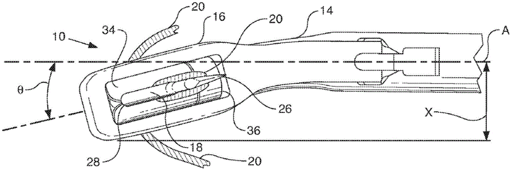
图1A示出了本公开的示例性成角缝线穿引器的侧视图,其中钳夹处于闭合位置;Figure 1A shows a side view of an exemplary angled suture passer of the present disclosure with the jaws in a closed position;
图1B示出了图1A的缝线穿引器,其中钳夹抓住组织并且针延伸通过组织;Figure 1B shows the suture passer of Figure 1A with the jaws grasping tissue and the needle extending through the tissue;
图1C示出了图1B的缝线穿引器的俯视图,其中组织被去除;FIG. 1C shows a top view of the suture passer of FIG. 1B with tissue removed;
图1D示出了成角缝线穿引器,其中钳夹处于打开位置并且针处于缩回配置;Figure ID shows an angled suture passer with the jaws in an open position and the needle in a retracted configuration;
图2A和2B示出了根据本公开的成角缝线穿引器的针的视图;2A and 2B show views of a needle of an angled suture passer according to the present disclosure;
图3A示出了在半月板根修复期间的左向成角缝线穿引器;以及Figure 3A shows a left angled suture passer during meniscal root repair; and
图3B示出了在半月板根修复期间的右向成角缝线穿引器。Figure 3B shows a right angled suture passer during meniscal root repair.
具体实施方式Detailed ways
在下面的描述中,相似的部件已被赋予相同的附图标记,而不管它们是否在不同的示例中示出。为了以清楚和简明的方式示出示例,附图可能不一定按比例绘制,并且某些特征可以以略微示意的形式示出。关于一个示例描述和/或示出的特征可以在一个或多个其它示例中以相同方式或以类似方式使用和/或与其它示例的特征组合或代替其它示例的特征。In the following description, similar components have been given the same reference numerals regardless of whether they are shown in different examples. In order to illustrate examples in a clear and concise manner, the drawings may not necessarily be to scale and certain features may be shown in somewhat schematic form. Features described and/or illustrated with respect to one example may be used in the same or similar manner in one or more other examples and/or in combination with or instead of features of other examples.
如说明书和权利要求书中所使用的,出于描述和定义本发明的目的,使用术语“约”和“大致”用于表示可以归因于任何定量比较、值、测量或其它表示的固有不确定度。术语“约”和“大致”也在本文中用于表示定量表示可以与所述基准不同而不会导致所讨论主题的基本功能发生变化的程度。“包括”、“包含”和/或每个的多个形式是开放式的并且包括列出的部分并且可以包括未列出的附加部分。“和/或”是开放式的并且包括一个或多个列出的部分和列出的部分的组合。As used in the specification and claims, for the purposes of describing and defining the present invention, the terms "about" and "approximately" are used to denote inherent differences that may be attributed to any quantitative comparison, value, measurement or other representation. Certainty. The terms "about" and "approximately" are also used herein to denote the degree by which a quantitative representation may vary from a stated reference without resulting in a change in the basic function of the subject matter at issue. Multiple forms of "comprising", "comprising" and/or each are open-ended and include the listed elements and may include additional elements not listed. "And/or" is open-ended and includes one or more of the listed parts and a combination of the listed parts.
现在参考图1A,示出了本公开的示例性缝线穿引器10的侧视图,其中第一平面被限定为平行于纵向轴线A并且平行于所示视图,使得方向B平行于第一平面。第二平面也在后面的讨论中被定义和依赖,其也与纵向轴线平行,并且垂直于第一平面,并且在图1C中最佳地示出。缝线穿引器10具有从手柄(未示出)延伸的细长轴12。管腔11延伸通过轴12。轴12的远端可以向下弯曲以终止于向远侧延伸的下钳夹14。或者,下钳夹14可以是独立元件(未示出),其联接到轴12的远端并从其向远侧延伸,并且可以联接成固定附接的固定钳夹。下钳夹14可以在近端处限定向下曲线,以便限定在下和上钳夹(分别为14和16)的两个面对表面之间的钳夹的近端处的开口或间隙19。这可以为布置在其中的组织提供间隙并且允许远端更靠近在一起。下钳夹14可以包括细长主体,所述细长主体具有布置在其中的细长通道40,并且如图1A中所示,钳夹限定沿着第一平面的第一曲线,其最初在近端处远离纵向轴线弯曲,在尖端或远端13处朝向并与纵向轴线交叉向后弯曲。沿着第一平面的第一曲线有助于保持两个钳夹(14和16)的远侧尖端更靠近在一起,并且还通过允许保持在细长通道(在图1A中以虚线示出)内并在后面描述的针18上的一些曲率有助于减小应力。在针朝向稍后将更详细地描述的上钳夹16延伸时,该第一曲线还有助于引导所述针18(稍后描述)。大致线性的上钳夹16附接到轴12,使得上钳夹16和下钳夹14可以在闭合位置偏置,如图所示。在示例中,上钳夹16可以相对于轴12围绕纵向轴线(A)枢转(如图所示),或者,下钳夹14和上钳夹16之间的连接可以是往复或凸轮系统,其中上钳夹16相对于下钳夹14可移动。上钳夹16的长度选择成使得其向远侧延伸超过下钳夹14。在示例中,缝线穿引器10的最宽直径为约8mm,或者以其它方式选择成适合8mm套管,其通常具有8.2mm的内径。有利地,缝线穿引器10的外边缘是圆形的,以在缝线穿引器10用于进入密闭空间时避免损坏周围的软骨和其它组织。Referring now to FIG. 1A , a side view of an
下钳夹14还包括横向通道30(在图1B和1D中最佳地看到),用于初始保持通过其中的一段缝线20以准备通过软组织缝合缝线20并随后捕获缝线20。组织接收区域19限定在下钳夹14、上钳夹16和轴12的远端之间。钳夹成形为使得区域19朝向钳夹的近端更大,作为用于布置在其中的组织的凹凸,同时朝向钳夹远端、邻近通道30仍保持两个钳夹之间的较小距离以有助于在操作期间的可靠缝线捕获。在示例中,上钳夹16的远端15的宽度选择成大于下钳夹14的远端13的宽度,使得当缝线穿引器10处于闭合位置时下钳夹14容纳在上钳夹16的相对向下延伸突起或齿17内。齿的位置有助于封闭和控制钳夹内的组织,同时不会过度压缩针18必须穿透的组织,使针18的动作更可靠。值得注意的是,在闭合位置,齿17不会阻塞下钳夹14中的通道30,使得缝线穿引器10在处于闭合位置时可以有效地穿过关节镜门。齿17与通道30向远侧间隔。在未示出的其它示例中,上钳夹16的宽度和下钳夹14的宽度可以大致相同。
在未示出的各种示例中,手柄是直列式手柄。手柄可以包括用于容纳用户手指的开口。在替代示例中,手柄不包括这样的开口,并且用户的手指简单地围绕手柄配合。手柄还可以包括一个或多个致动器以相对于下钳夹14打开/关闭上钳夹16和/或使针18延伸/缩回。例如,致动器可以是拇指启动滑块的形式,其可以远离手柄向远侧移动以启动缝线穿引器10。致动器可以通过合适的装置(例如弹簧)偏置以在移除施加力时(例如在用户从手指或拇指移除压力时)默认为闭合/缩回位置。在其它示例中,手柄可以是具有合适的致动构件的剪式把手或手枪式把手型手柄。在示例中,缝线穿引器10可以包括用于缝线的相对端部的两个槽以允许在后续步骤中穿过半月板的两个部分,产生用于垂直撕裂的垂直褥式缝合或环形缝合。因此,针18可以在手柄内的位置之间移动以拾取第二股缝线。In various examples not shown, the handle is an in-line handle. The handle may include openings for receiving a user's fingers. In an alternative example, the handle does not include such an opening, and the user's fingers simply fit around the handle. The handle may also include one or more actuators to open/close the
现在转到图1B,可以看出,用于使缝线20穿过诸如半月板组织的软组织22的弯曲针18配置成在轴12的管腔11内和下钳夹14的通道40内轴向可移动并从其可延伸,使得针尖26可以从缩回位置移动到延伸位置,在所述缩回位置针18从组织接收区域19撤回或防护,在所述延伸位置针18移位通过上钳夹16中的开口并通过软组织22。针18可以沿着下钳夹14的一部分容纳在第一位置,其中针尖与横向通道30相邻并略微缩回。下钳夹14可以包括沿着其长度的通道40以便在第一位置容纳和保护针18,该通道具有与下钳夹的横向通道30相邻的远侧斜坡41(图1D),以便将针18朝向横向通道30引导以可靠地拾取布置在横向通道30内的一段缝线20。由于针18在其无应力配置(稍后描述)中弯曲,其限定了当针延伸出通道40时的针轨迹,因此斜坡41不被认为是用于显著改变针的延伸轨迹的装置,仅仅是有助于在通道30附近可靠捕获缝线的局部控制表面。当针延伸并释放到其预形成几何形状时,针在图1B中示出为大致垂直于纵向轴线A弯曲并且甚至可能在近侧方向上弯曲。因此可以不需要斜坡,并且没有斜坡或下钳夹14的敞开远端13可能就足够了。与此相反,如果针18在没有如所公开的预形成曲线的情况下生产,则可能需要斜坡或缓冲器来引起针轨迹,所述针轨迹将主要从斜坡线性地延伸并且不会继续大致垂直于纵向轴线A和可能在稍微近侧方向上弯曲,如图1B中所示。如图1B中所示,针尖26相对于缝线通道30更向近侧布置。该弯曲轨迹使针尖26保持靠近上钳夹16而不是远离其延伸,当针尖移动通过并远离上钳夹16时这有助于减少针尖26可能对组织造成的损伤。壳体40可以具有被覆盖部分42以更好地抓住组织并保护针18和壳体40免受组织的伤害。壳体40可以沿着前面关于图1A讨论的第一平面弯曲,从而减小针18上的应力并改善与上钳夹16的缝线捕获孔34的接合可靠性。该被覆盖部分42可以有助于将预形成针18保持在壳体40内。Turning now to FIG. 1B , it can be seen that a
在示例中,针18的至少远侧部分由超弹性材料(例如镍钛诺)组成,并且具有大致圆形的横截面。圆形横截面提供一些增加的横向刚度,并有助于针18在其延伸通过组织和上钳夹16时保持其路径。针18可以是大致中空的或大致非中空的。针18可以是锥形的,并且可以具有邻近针的远侧尖端的较小直径的长度18a或非圆形横截面,以及从其向近侧延伸的较大直径的长度18b。这可以允许通过下述的缝线捕获构件34更容易地插入。材料的超弹性允许针18相对于其预形成形状以大致线性配置布置,同时放置在缩回位置,以便容易地与下钳夹14内的壳体40一致,并且然后在针18从缩回位置移动到延伸位置期间返回到更接近预形成的弯曲配置的形状。如图2A中所示,针18预形成为包括在针18的远端处的弯曲或曲线区域25,其示出了在无应力配置中与缝线穿引器10组装之前的针18。弯曲区域25可以限定沿着如前所述的第一平面的预形成曲线,其平行于轴的纵向轴线和针的近端,该曲线在图2A和2B中容易看到。当组装在与下钳夹14的曲线大体一致的下钳夹14的壳体或通道40内时,针被置于应力配置,由此针曲率25沿着第一平面伸直并沿着第二平面弯曲,如前所述;沿着第二平面的曲线引起针通过布置在钳夹之间的组织的横向偏移放置,如图1C中所示。在未示出的替代实施例中,针18可以被制造成具有更复杂的曲线,或者沿着第一平面和第二平面两者预形成的曲线,以便调节或补偿通道40的诱导横向曲线(第二平面)。例如,该更复杂的曲线可以在与钳夹的角偏移相反的方向上,以便通过下钳夹曲线抵抗沿第二平面的诱导曲线。因此,预形成针18可以相对于钳夹的角在相反方向上在一定程度上引导针尖26。In an example, at least a distal portion of
在示例中,在延伸位置,针18限定如图1B和2A所示的至少一个曲线,其具有大于或等于针18的厚度(T)的3倍的第一曲率半径R。此外,在如图1A和1D所示的缩回位置,针18限定至少一个曲线R'(未示出),其具有选择成大于第一曲率半径的第二曲率半径。在针18的完全延伸位置,已被牵引通过组织22的缝线20形成缝线部分21,所述缝线部分从上钳夹16突出并布置在上钳夹上方。在示例中,缝线部分21可以形成环形配置。In an example, in the extended position,
仍然参考图1B,上钳夹16可以由手柄致动以移动到打开位置,以使缝线穿引器10能够将组织22固定在上钳夹16和下钳夹14之间。在组织22在上钳夹16和下钳夹14之间被抓住的情况下,针18可以通过手柄中的针部署构件或触发器的致动部署到延伸位置。针18朝向缝线穿引器10的远端轴向前进,使得针18的横向开口24(其可以是面向远侧的钩的形式)接合容纳在下钳夹14的通道30中的缝线20。当针18在大致远侧方向上前进时,针18的弯曲区域25朝向无应力配置逐渐释放以便朝向上钳夹16推动针尖26,并且针尖26由此穿透并进入在上钳夹16和下钳夹14之间抓住的软组织22的下侧。当针18前进通过软组织22时,突起或齿17有助于将组织22保持在组织接收区域19内。为了有助于保持通过组织的可靠针和由此缝合轨迹,针横截面优选地是圆形横截面,并且目标组织保持相对未压缩;压缩组织被认为更耐穿刺并且更可能改变针18通过其中的路径。该相对未压缩的组织通过提供凹凸的下钳夹和上钳夹的相对面上的内侧凸起部分或腔以及围绕上钳夹的外侧周边布置以保持组织的齿17来实现。图1D示出了邻近通道30的下钳夹14上的腔。在其中被抓住的组织22的厚度为约3mm的示例中,针18的长度被选择成使得针18的远侧部分延伸到上钳夹16上方不超过约3mm至约4mm,以避免与周围组织接触。Still referring to FIG. 1B ,
图1C在俯视表面图中示出了图1B的缝线穿引器10,其中为简单起见去除了组织。在图1C中,可以看出缝线捕获构件34布置在上钳夹16中的开口36内,缝线捕获构件限定弯曲挠性构造,所述弯曲挠性构造限定上钳夹16的内侧腔。缝线捕获构件34可以是可移除的盒的形式或可以是上钳夹16的一体结构部件。缝线捕获构件的详细描述和示例可以在共同转让的美国专利9,211,118中找到,其全部公开内容通过引用并入本文。在示例中,缝线捕获构件34由高温弹簧钢材料构成。FIG. 1C shows the
还如图1C中所示,上钳夹16和下钳夹14沿着第二平面远离轴12的纵向轴线(A)侧向成角或弯曲。从上方看,上钳夹16和下钳夹14可以向左(如图所示)或向右成角,角Θ与轴12的纵向轴线(A)成45度,并且优选在10-25度之间。角Θ主要沿着钳夹14和16的一部分形成,与捕获构件34在近侧间隔,使得两个钳夹的更远侧部分可以是直的。角Θ使钳夹的尖端从纵向轴线偏移距离X,所述距离可以在1-8mm的范围内,并且更优选地,对于8mm的装置,在2-5mm的范围内。对于针对患者的替代区域的其它装置,设想更大或更小的角和偏移,并且一般而言,在给定手术和患者解剖结构的情况下,该角和侧向偏移可以是改善通过弯曲空间的目标组织通路的任何非零值。在未示出的其它示例中,上钳夹16和下钳夹14可以从轴12的纵向轴线(A)向上成角以允许缝线穿引器10定位在碟形内侧隔室的后部。本公开还预期上钳夹16和下钳夹14可以遵循沿着第二平面远离纵向轴线(A)延伸的半径或螺旋弧。有利地,成角缝线穿引器10在通过形成于膝关节的股骨髁之间的股骨切迹插入时为外科医生提供更大的通路空间。钳夹(14、16)显示为遵循相同的角偏移(相对于彼此,以便相对于彼此平行延伸)。在替代实施例(未示出)中,每个钳夹可以具有彼此略微不同的成角偏移,以便交错并且可能在针延伸通过组织22时对于针18的改变路径进行调节。发明人已发现,如果针18制造成仅在单个平面中弯曲,如图2A和2B中所示,针18可以从壳体40出来,抵靠最接近缝线穿引器10的纵向轴线A的侧壁偏置而不在壳体40的中心。针18可以沿着纵向轴线沿着可靠的轨迹继续;然而,由于与侧壁的接合,它可能相对于缝线捕获孔28侧向偏移。因此提供具有减小的偏移的上钳夹可以补偿该轨迹变化并且改善针与缝线捕获构件34的接合。例如,角Θ在下钳夹14上可以比在上钳夹16上小0-5度,或者下钳夹14可以与纵向轴线A成17度角,而上钳夹16可以与纵向轴线A成18度角。As also shown in FIG. 1C ,
图3A和3B进一步示出了在半月板修复期间穿过膝关节的股骨切迹32的如前所述的成角缝线穿引器10。为简单起见,图中未示出捕获的缝线(20)。图3A示出了左向成角缝线穿引器10,并且图3B示出了右向成角缝线穿引器10。缝线捕获构件34的进一步细节也在图3A中示出。在图3A中,可以看出缝线捕获构件34包括由每个相对侧上的边缘38形成的细长孔28。边缘38限定缝线捕获表面,其可以配置为相对锯齿状边缘(如图所示),针18和缝线的一部分穿过所述相对锯齿状边缘。本公开还预期缝线捕获表面可以包括多个交叉齿,多个相对凹口或其它类似的相对边缘特征。在示例中,孔28的尺寸被选择成足够大,使得缝线捕获构件34在移位到延伸位置期间不限制针18的移动。然而,孔28的尺寸也被选择成足够小以防止缝线20通过缝线捕获构件34穿回。孔28沿着上钳夹的中心轴线布置,并且与针18离开的下钳夹14中的出口开口成直线或在其正上方。在替代实施例中,该孔28可以与出口开口(未示出)略微侧向偏移(0-2mm),或者可以相对于下钳夹轴线成角以更好地捕获针18和缝线20,在给定针18的弹性性质、针的预形成形状和由下钳夹壳体40和斜坡41和钳夹曲线引导的诱导针迹之间的相互作用的情况下,该偏移或成角是补偿针18的潜在路径的替代手段。3A and 3B further illustrate the angled
现在回到图1A-C,在操作中,用户(例如,外科医生)可以将缝线穿引器10通过未示出的套管插入修复部位。通常,缝线穿引器10预装有缝线20(图1A)。缝线20可以是附接有缝线20的穿梭缝线,或者它可以是已经定位在组织22内的缝线20。一旦缝线穿引器10靠近待缝合的组织22,缝线穿引器10就被致动使得组织22可以定位在下钳夹14和上钳夹16之间。该目标组织22可以位于偏离缝线穿引器的纵向轴线的位置,缝线穿引器的远端具有弯曲或成角部分以便更好地接近该目标组织22。一旦目标组织22如此定位,针18可以至少部分地被致动以将缝线20捕获在缝线捕获构件24上。针18可以进一步被致动以穿透组织22,穿透在下钳夹和上钳夹(14、16)内侧的位置处并且从缝线穿引器10的纵向轴线侧向偏移并形成用于缝线20的通道。在针尖26和缝线20牵引通过软组织22的情况下,针18的致动继续,直到针18前进进入并通过上钳夹16中的开口36(图1C)。同时,针18和缝线20也被引导穿过缝线捕获构件34的孔28。Returning now to FIGS. 1A-C , in operation, a user (eg, a surgeon) may insert
尽管已参考其优选实施例具体示出和描述了本公开,但是本领域技术人员将理解,在不脱离由所附权利要求限定的本申请的精神和范围的情况下,可以在形式和细节上进行各种改变。这样的变化旨在由本申请的范围涵盖。因而,本申请的示例的前述描述并非旨在限制,而是由所附权利要求传达完整范围。While the present disclosure has been particularly shown and described with reference to preferred embodiments thereof, it will be understood by those skilled in the art that changes may be made in form and detail without departing from the spirit and scope of the application as defined by the appended claims. Make various changes. Such variations are intended to be covered by the scope of this application. Accordingly, the foregoing description of examples of the present application is not intended to be limiting, but rather the full scope is conveyed by the appended claims.
Claims (16)
Applications Claiming Priority (3)
| Application Number | Priority Date | Filing Date | Title |
|---|---|---|---|
| US201762478204P | 2017-03-29 | 2017-03-29 | |
| US62/478,204 | 2017-03-29 | ||
| PCT/US2018/025138 WO2018183670A2 (en) | 2017-03-29 | 2018-03-29 | Angled suture passer and method of use thereof |
Publications (2)
| Publication Number | Publication Date |
|---|---|
| CN110402110A CN110402110A (en) | 2019-11-01 |
| CN110402110B true CN110402110B (en) | 2023-04-28 |
Family
ID=62025973
Family Applications (1)
| Application Number | Title | Priority Date | Filing Date |
|---|---|---|---|
| CN201880017172.6A Active CN110402110B (en) | 2017-03-29 | 2018-03-29 | Angled suture passer and method of use |
Country Status (6)
| Country | Link |
|---|---|
| US (1) | US11452521B2 (en) |
| EP (1) | EP3600076A2 (en) |
| JP (1) | JP7195263B2 (en) |
| CN (1) | CN110402110B (en) |
| AU (1) | AU2018244465B2 (en) |
| WO (1) | WO2018183670A2 (en) |
Families Citing this family (8)
| Publication number | Priority date | Publication date | Assignee | Title |
|---|---|---|---|---|
| US10765422B2 (en) * | 2012-03-05 | 2020-09-08 | Passer Stitch, Llc | Apparatus and method for passing suture through soft tissue |
| US10085738B2 (en) | 2016-05-16 | 2018-10-02 | Arthex, Inc. | Knee joint capsular disruption and repair |
| US10828021B2 (en) | 2018-05-21 | 2020-11-10 | Arthrex, Inc. | Systems and methods for anchor placement |
| CN111265261A (en) * | 2020-03-23 | 2020-06-12 | 苏州市永旭精密五金制品厂 | Electric powered rotator cuff repair device |
| CN113081220B (en) * | 2021-03-22 | 2022-07-29 | 宁波大学医学院附属医院 | Meniscus threading device |
| EP4472524A4 (en) * | 2022-01-31 | 2025-10-01 | William H Simon | SURGICAL DEVICES AND METHODS FOR ACHILLES TENDON REPAIR |
| KR102780862B1 (en) * | 2022-09-28 | 2025-03-13 | 고려대학교 산학협력단 | Endoscopic suturing apparatus |
| CN116269563A (en) * | 2023-02-14 | 2023-06-23 | 杭州锐健马斯汀医疗器材有限公司 | Suture box of suture device, suture device and suture method |
Citations (4)
| Publication number | Priority date | Publication date | Assignee | Title |
|---|---|---|---|---|
| US6446854B1 (en) * | 1991-10-18 | 2002-09-10 | United States Surgical Corporation | Surgical stapling apparatus |
| CN101637402A (en) * | 2009-10-23 | 2010-02-03 | 天津大学 | Minimally invasive surgical wire driving and four-freedom surgical tool |
| WO2013055390A1 (en) * | 2011-10-03 | 2013-04-18 | Smith & Nephew, Inc. | Meniscal root attachment repair |
| EP2929841A1 (en) * | 2014-04-08 | 2015-10-14 | Ceterix Orthopaedics, Inc. | Suture passers adapted for use in constrained regions |
Family Cites Families (17)
| Publication number | Priority date | Publication date | Assignee | Title |
|---|---|---|---|---|
| US6235057B1 (en) * | 1995-01-24 | 2001-05-22 | Smith & Nephew, Inc. | Method for soft tissue reconstruction |
| US7842050B2 (en) | 2001-02-26 | 2010-11-30 | Diduch David R | Suture passing devices |
| US6719765B2 (en) * | 2001-12-03 | 2004-04-13 | Bonutti 2003 Trust-A | Magnetic suturing system and method |
| DE60328490D1 (en) * | 2002-06-12 | 2009-09-03 | Boston Scient Ltd | SEAM INSTRUMENTS |
| US7166116B2 (en) * | 2003-06-23 | 2007-01-23 | Ethicon, Inc. | Tissue grasper/suture passer instrument |
| US7815652B2 (en) * | 2006-03-21 | 2010-10-19 | Ethicon Endo-Surgery, Inc. | Surgical fastener and instrument |
| US8100922B2 (en) * | 2007-04-27 | 2012-01-24 | Ethicon Endo-Surgery, Inc. | Curved needle suturing tool |
| US8465505B2 (en) * | 2011-05-06 | 2013-06-18 | Ceterix Orthopaedics, Inc. | Suture passer devices and methods |
| US9861354B2 (en) * | 2011-05-06 | 2018-01-09 | Ceterix Orthopaedics, Inc. | Meniscus repair |
| US20090131956A1 (en) | 2007-11-08 | 2009-05-21 | Jonathan Dewey | Method and apparatus for passing suture through the labrum of a hip joint in order to secure the labrum to the acetabulum |
| US8177795B2 (en) * | 2008-10-21 | 2012-05-15 | Cayenne Medical, Inc. | Meniscal repair systems and methods |
| US9011454B2 (en) * | 2009-11-09 | 2015-04-21 | Ceterix Orthopaedics, Inc. | Suture passer with radiused upper jaw |
| US9211118B2 (en) | 2009-11-16 | 2015-12-15 | Arthrocare Corporation | Suture passer |
| WO2011123714A1 (en) * | 2010-03-31 | 2011-10-06 | Siesta Medical, Inc. | Suture passer systems and methods for tongue or other tissue suspension and compression |
| US10524778B2 (en) | 2011-09-28 | 2020-01-07 | Ceterix Orthopaedics | Suture passers adapted for use in constrained regions |
| US9888914B2 (en) * | 2015-06-16 | 2018-02-13 | Ethicon Endo-Surgery, Llc | Suturing instrument with motorized needle drive |
| US9439647B1 (en) | 2016-03-02 | 2016-09-13 | Arthrogenx, LLC. | Suture passing instruments and methods |
-
2018
- 2018-03-29 CN CN201880017172.6A patent/CN110402110B/en active Active
- 2018-03-29 WO PCT/US2018/025138 patent/WO2018183670A2/en not_active Ceased
- 2018-03-29 EP EP18718993.1A patent/EP3600076A2/en active Pending
- 2018-03-29 US US15/939,934 patent/US11452521B2/en active Active
- 2018-03-29 AU AU2018244465A patent/AU2018244465B2/en active Active
- 2018-03-29 JP JP2019548304A patent/JP7195263B2/en active Active
Patent Citations (4)
| Publication number | Priority date | Publication date | Assignee | Title |
|---|---|---|---|---|
| US6446854B1 (en) * | 1991-10-18 | 2002-09-10 | United States Surgical Corporation | Surgical stapling apparatus |
| CN101637402A (en) * | 2009-10-23 | 2010-02-03 | 天津大学 | Minimally invasive surgical wire driving and four-freedom surgical tool |
| WO2013055390A1 (en) * | 2011-10-03 | 2013-04-18 | Smith & Nephew, Inc. | Meniscal root attachment repair |
| EP2929841A1 (en) * | 2014-04-08 | 2015-10-14 | Ceterix Orthopaedics, Inc. | Suture passers adapted for use in constrained regions |
Also Published As
| Publication number | Publication date |
|---|---|
| AU2018244465B2 (en) | 2023-11-02 |
| WO2018183670A2 (en) | 2018-10-04 |
| CN110402110A (en) | 2019-11-01 |
| US11452521B2 (en) | 2022-09-27 |
| US20180280018A1 (en) | 2018-10-04 |
| JP2020512062A (en) | 2020-04-23 |
| JP7195263B2 (en) | 2022-12-23 |
| AU2018244465A1 (en) | 2019-09-26 |
| EP3600076A2 (en) | 2020-02-05 |
| WO2018183670A3 (en) | 2018-11-15 |
Similar Documents
| Publication | Publication Date | Title |
|---|---|---|
| CN110402110B (en) | Angled suture passer and method of use | |
| US7118583B2 (en) | Meniscal suturing instrument and method | |
| US9700299B2 (en) | Suture passer devices and methods | |
| EP2498688B1 (en) | Devices, systems and methods for meniscus repair | |
| EP2939604B1 (en) | Suture passer with radiused upper jaw | |
| US20050234481A1 (en) | Suture cutting device | |
| JP5597252B2 (en) | Meniscal repair system and method | |
| JP2012502688A (en) | Surgical instrument for cutting tissue and method of use | |
| CN113891690A (en) | Tendon harvesting system | |
| EP2884905B1 (en) | Suturing device for treament of pelvic floor disorders | |
| CA2660117C (en) | Insertion system for implanting a medical device and surgical methods | |
| US20200352561A1 (en) | Suture passer and related method | |
| US20220265265A1 (en) | Meniscus suture device | |
| JP7278486B2 (en) | surgical instruments |
Legal Events
| Date | Code | Title | Description |
|---|---|---|---|
| PB01 | Publication | ||
| PB01 | Publication | ||
| SE01 | Entry into force of request for substantive examination | ||
| SE01 | Entry into force of request for substantive examination | ||
| GR01 | Patent grant | ||
| GR01 | Patent grant |