CN110382822B - Hydraulic machine with stepped roller blades and fluid power system including hydraulic machine with starter motor function - Google Patents
Hydraulic machine with stepped roller blades and fluid power system including hydraulic machine with starter motor function Download PDFInfo
- Publication number
- CN110382822B CN110382822B CN201880015900.XA CN201880015900A CN110382822B CN 110382822 B CN110382822 B CN 110382822B CN 201880015900 A CN201880015900 A CN 201880015900A CN 110382822 B CN110382822 B CN 110382822B
- Authority
- CN
- China
- Prior art keywords
- rotor
- vane
- vanes
- hydraulic fluid
- hydraulic
- Prior art date
- Legal status (The legal status is an assumption and is not a legal conclusion. Google has not performed a legal analysis and makes no representation as to the accuracy of the status listed.)
- Active
Links
Images


Classifications
-
- F—MECHANICAL ENGINEERING; LIGHTING; HEATING; WEAPONS; BLASTING
- F01—MACHINES OR ENGINES IN GENERAL; ENGINE PLANTS IN GENERAL; STEAM ENGINES
- F01C—ROTARY-PISTON OR OSCILLATING-PISTON MACHINES OR ENGINES
- F01C21/00—Component parts, details or accessories not provided for in groups F01C1/00 - F01C20/00
- F01C21/08—Rotary pistons
- F01C21/0809—Construction of vanes or vane holders
- F01C21/0818—Vane tracking; control therefor
- F01C21/0854—Vane tracking; control therefor by fluid means
- F01C21/0863—Vane tracking; control therefor by fluid means the fluid being the working fluid
-
- F—MECHANICAL ENGINEERING; LIGHTING; HEATING; WEAPONS; BLASTING
- F04—POSITIVE - DISPLACEMENT MACHINES FOR LIQUIDS; PUMPS FOR LIQUIDS OR ELASTIC FLUIDS
- F04C—ROTARY-PISTON, OR OSCILLATING-PISTON, POSITIVE-DISPLACEMENT MACHINES FOR LIQUIDS; ROTARY-PISTON, OR OSCILLATING-PISTON, POSITIVE-DISPLACEMENT PUMPS
- F04C15/00—Component parts, details or accessories of machines, pumps or pumping installations, not provided for in groups F04C2/00 - F04C14/00
- F04C15/0088—Lubrication
-
- F—MECHANICAL ENGINEERING; LIGHTING; HEATING; WEAPONS; BLASTING
- F01—MACHINES OR ENGINES IN GENERAL; ENGINE PLANTS IN GENERAL; STEAM ENGINES
- F01C—ROTARY-PISTON OR OSCILLATING-PISTON MACHINES OR ENGINES
- F01C21/00—Component parts, details or accessories not provided for in groups F01C1/00 - F01C20/00
- F01C21/08—Rotary pistons
- F01C21/0809—Construction of vanes or vane holders
- F01C21/0818—Vane tracking; control therefor
- F01C21/0827—Vane tracking; control therefor by mechanical means
- F01C21/0836—Vane tracking; control therefor by mechanical means comprising guiding means, e.g. cams, rollers
-
- F—MECHANICAL ENGINEERING; LIGHTING; HEATING; WEAPONS; BLASTING
- F01—MACHINES OR ENGINES IN GENERAL; ENGINE PLANTS IN GENERAL; STEAM ENGINES
- F01C—ROTARY-PISTON OR OSCILLATING-PISTON MACHINES OR ENGINES
- F01C21/00—Component parts, details or accessories not provided for in groups F01C1/00 - F01C20/00
- F01C21/08—Rotary pistons
- F01C21/0809—Construction of vanes or vane holders
- F01C21/0881—Construction of vanes or vane holders the vanes consisting of two or more parts
-
- F—MECHANICAL ENGINEERING; LIGHTING; HEATING; WEAPONS; BLASTING
- F04—POSITIVE - DISPLACEMENT MACHINES FOR LIQUIDS; PUMPS FOR LIQUIDS OR ELASTIC FLUIDS
- F04C—ROTARY-PISTON, OR OSCILLATING-PISTON, POSITIVE-DISPLACEMENT MACHINES FOR LIQUIDS; ROTARY-PISTON, OR OSCILLATING-PISTON, POSITIVE-DISPLACEMENT PUMPS
- F04C14/00—Control of, monitoring of, or safety arrangements for, machines, pumps or pumping installations
- F04C14/06—Control of, monitoring of, or safety arrangements for, machines, pumps or pumping installations specially adapted for stopping, starting, idling or no-load operation
-
- F—MECHANICAL ENGINEERING; LIGHTING; HEATING; WEAPONS; BLASTING
- F04—POSITIVE - DISPLACEMENT MACHINES FOR LIQUIDS; PUMPS FOR LIQUIDS OR ELASTIC FLUIDS
- F04C—ROTARY-PISTON, OR OSCILLATING-PISTON, POSITIVE-DISPLACEMENT MACHINES FOR LIQUIDS; ROTARY-PISTON, OR OSCILLATING-PISTON, POSITIVE-DISPLACEMENT PUMPS
- F04C15/00—Component parts, details or accessories of machines, pumps or pumping installations, not provided for in groups F04C2/00 - F04C14/00
- F04C15/06—Arrangements for admission or discharge of the working fluid, e.g. constructional features of the inlet or outlet
-
- F—MECHANICAL ENGINEERING; LIGHTING; HEATING; WEAPONS; BLASTING
- F04—POSITIVE - DISPLACEMENT MACHINES FOR LIQUIDS; PUMPS FOR LIQUIDS OR ELASTIC FLUIDS
- F04C—ROTARY-PISTON, OR OSCILLATING-PISTON, POSITIVE-DISPLACEMENT MACHINES FOR LIQUIDS; ROTARY-PISTON, OR OSCILLATING-PISTON, POSITIVE-DISPLACEMENT PUMPS
- F04C2/00—Rotary-piston machines or pumps
- F04C2/30—Rotary-piston machines or pumps having the characteristics covered by two or more groups F04C2/02, F04C2/08, F04C2/22, F04C2/24 or having the characteristics covered by one of these groups together with some other type of movement between co-operating members
- F04C2/34—Rotary-piston machines or pumps having the characteristics covered by two or more groups F04C2/02, F04C2/08, F04C2/22, F04C2/24 or having the characteristics covered by one of these groups together with some other type of movement between co-operating members having the movement defined in groups F04C2/08 or F04C2/22 and relative reciprocation between the co-operating members
- F04C2/344—Rotary-piston machines or pumps having the characteristics covered by two or more groups F04C2/02, F04C2/08, F04C2/22, F04C2/24 or having the characteristics covered by one of these groups together with some other type of movement between co-operating members having the movement defined in groups F04C2/08 or F04C2/22 and relative reciprocation between the co-operating members with vanes reciprocating with respect to the inner member
- F04C2/3446—Rotary-piston machines or pumps having the characteristics covered by two or more groups F04C2/02, F04C2/08, F04C2/22, F04C2/24 or having the characteristics covered by one of these groups together with some other type of movement between co-operating members having the movement defined in groups F04C2/08 or F04C2/22 and relative reciprocation between the co-operating members with vanes reciprocating with respect to the inner member the inner and outer member being in contact along more than one line or surface
- F04C2/3447—Rotary-piston machines or pumps having the characteristics covered by two or more groups F04C2/02, F04C2/08, F04C2/22, F04C2/24 or having the characteristics covered by one of these groups together with some other type of movement between co-operating members having the movement defined in groups F04C2/08 or F04C2/22 and relative reciprocation between the co-operating members with vanes reciprocating with respect to the inner member the inner and outer member being in contact along more than one line or surface the vanes having the form of rollers, slippers or the like
-
- F—MECHANICAL ENGINEERING; LIGHTING; HEATING; WEAPONS; BLASTING
- F04—POSITIVE - DISPLACEMENT MACHINES FOR LIQUIDS; PUMPS FOR LIQUIDS OR ELASTIC FLUIDS
- F04C—ROTARY-PISTON, OR OSCILLATING-PISTON, POSITIVE-DISPLACEMENT MACHINES FOR LIQUIDS; ROTARY-PISTON, OR OSCILLATING-PISTON, POSITIVE-DISPLACEMENT PUMPS
- F04C2240/00—Components
- F04C2240/50—Bearings
- F04C2240/56—Bearing bushings or details thereof
Landscapes
- Engineering & Computer Science (AREA)
- Mechanical Engineering (AREA)
- General Engineering & Computer Science (AREA)
- Rotary Pumps (AREA)
- Hydraulic Motors (AREA)
- Wind Motors (AREA)
Abstract
公开了用于液压装置的多个设计,多个设计包括液压装置,液压装置可包括转子、叶片和环。转子可设置成绕轴线旋转。多个叶片可分别包括叶片台阶。多个叶片中的每个叶片可相对于转子在缩回位置和延伸位置之间移动,在延伸位置处,多个叶片对被引入至转子附近的液压流体作功。辊可以安装到多个叶片中的每个叶片的尖端。环可以至少部分地围绕转子设置。转子可包括一个或多个通道,一个或多个通道用于使液压流体进入或离开与叶片台阶相邻并且至少由转子和叶片台阶限定的区域。

A number of designs are disclosed for hydraulic devices including hydraulic devices, which may include rotors, vanes, and rings. The rotor may be arranged to rotate about an axis. The plurality of vanes may each include vane steps. Each of the plurality of vanes is movable relative to the rotor between a retracted position and an extended position where the plurality of vanes perform work on hydraulic fluid introduced into the vicinity of the rotor. A roller may be mounted to the tip of each of the plurality of blades. The ring may be disposed at least partially around the rotor. The rotor may include one or more passages for the passage of hydraulic fluid into or out of an area adjacent to the vane step and defined at least by the rotor and the vane step.
Description
优先权要求priority claim
本申请要求2017年3月6日提交的名称为“包括具有启动马达功能的液压机械的具有台阶式辊叶片和流体动力系统的液压机械”的美国临时申请No.62/467,658和2017年5月10日提交的名称为“包括具有启动马达功能的液压机械的具有台阶式辊叶片和流体动力系统的液压机械”的美国临时申请No.62/504,283的优先权,上述每个申请的全部说明书均通过引用而被纳入本文。This application claims US Provisional Application No. 62/467,658, filed March 6, 2017, and entitled "Hydraulic Machine with Stepped Roller Blades and Fluid Power System Including Hydraulic Machine with Starter Motor Function" and May 2017 Priority to U.S. Provisional Application No. 62/504,283, filed on 10, entitled "Hydraulic Machine with Stepped Roller Blades and Fluid Power System Including Hydraulic Machine with Starter Motor Function," the entire specification of each of which is Incorporated herein by reference.
相关申请的交叉引用CROSS-REFERENCE TO RELATED APPLICATIONS
本申请要求2017年5月10日提交的名称为“包括具有启动马达功能的液压机械的具有台阶式辊叶片和流体动力系统的液压机械”的美国临时申请No.62/504,283和2017年3月6日提交的名称为“包括具有启动马达功能的液压机械的具有台阶式辊叶片和流体动力系统的液压机械”的美国临时申请No.62/467,658的优先权,上述每个申请的全部说明书均通过引用而被纳入本文。This application claims US Provisional Application No. 62/504,283, filed May 10, 2017, and entitled "Hydraulic Machine with Stepped Roller Blades and Fluid Power System Including Hydraulic Machine with Starter Motor Function" and March 2017 Priority to U.S. Provisional Application No. 62/467,658, filed on 6th, entitled "Hydraulic Machine with Stepped Roller Blades and Fluid Power System Including Hydraulic Machine with Starter Motor Function," the entire specification of each of which is Incorporated herein by reference.
本申请涉及2007年6月1日提交的名称为“用于泵送液压流体的叶片泵”的公开号为WO/2007/140514的国际申请No.PCT/AU2007/000772;2006年5月12日提交的名称为“改进的叶片泵”的公开号为WO/2006/119574的国际申请No.PCT/AU2006/000623;2004年7月15日提交的名称为“液压机械”的公开号为WO/2005/005782的国际申请No.PCT/AU2004/00951;和2012年12月5日提交的名称为“液压控制式旋转式联接器”的公开号为U.S.2013/0067899的美国专利申请No.13/510,643,上述每个申请的全部说明书均通过引用而被纳入本文。This application is related to International Application No. PCT/AU2007/000772, filed June 1, 2007, and entitled "Vane Pump for Pumping Hydraulic Fluid", with publication number WO/2007/140514; May 12, 2006 International application No. PCT/AU2006/000623, filed titled "Improved Vane Pump" with publication number WO/2006/119574; filed on July 15, 2004, titled "Hydraulic Machinery", with publication number WO/ International Application No. PCT/AU2004/00951 of 2005/005782; and US Patent Application No. 13/, filed December 5, 2012, entitled "Hydraulically Controlled Rotary Coupling," Publication No. U.S. 2013/0067899 510,643, the entire specification of each of the above applications is incorporated herein by reference.
技术领域technical field
本专利申请总体上涉及液压装置,更具体地,涉及包括阶梯式辊叶片的液压机械。The present patent application relates generally to hydraulic devices and, more particularly, to hydraulic machines including stepped roller blades.
背景技术Background technique
液压叶片泵在用于不同目的的许多不同类型的机械中用于泵送液压流体。这种机械包括例如运输车辆,农业机械,工业机械,风力涡轮机和海上交通工具(例如拖网渔船)。Hydraulic vane pumps are used to pump hydraulic fluid in many different types of machinery used for different purposes. Such machinery includes, for example, transport vehicles, agricultural machinery, industrial machinery, wind turbines, and marine vehicles (eg, fishing trawlers).
旋转式联接器还用于运输车辆,工业机械和农业机械中以传递旋转机械动力。例如,旋转式联接器已被用于汽车变速器中作为机械离合器的替代品。旋转式联接器的使用在变速操作和受控启动的应用中也很普遍。Rotary couplings are also used in transport vehicles, industrial machinery and agricultural machinery to transmit rotating machinery power. For example, rotary couplings have been used in automotive transmissions as a replacement for mechanical clutches. The use of rotary couplings is also common in variable speed operation and controlled starting applications.
发明内容SUMMARY OF THE INVENTION
本发明人已经认识到,与传统的可变活塞泵/马达液压装置和甚至标准的叶片泵或马达相比,具有叶片的液压装置可以提供改进的功率密度和使用寿命。叶片泵或叶片马达中的标准叶片的缺点是限制了叶片尖端和环形轮廓之间的摩擦力。当叶片尖端穿透在尖端和环形轮廓之间润滑的油膜时,这受到速度和压力的限制。当油膜被穿透时,表面之间没有润滑并且可能发生故障。本发明公开的液压装置和系统利用流体静力润滑的辊轴承,辊轴承去除叶片和环形轮廓之间的摩擦运动。因此,改进的性能和更长的使用寿命可以由目前公开的设计产生。这是因为叶片尖端不再对速度和压力敏感。通过本文公开的附加设计变化,目前讨论的装置(例如,可以作为泵和马达操作的液压联接器)可以在更高的压力下运行。The present inventors have recognized that hydraulics with vanes can provide improved power density and service life compared to conventional variable piston pump/motor hydraulics and even standard vane pumps or motors. The disadvantage of standard vanes in vane pumps or vane motors is that they limit the friction between the vane tips and the annular profile. This is limited by speed and pressure as the blade tip penetrates the oil film lubricated between the tip and the annular profile. When the oil film is penetrated, there is no lubrication between the surfaces and failure can occur. The hydraulic devices and systems disclosed herein utilize hydrostatically lubricated roller bearings that remove frictional motion between the vanes and the annular profile. Thus, improved performance and longer service life can result from the presently disclosed designs. This is because the blade tips are no longer speed and pressure sensitive. With additional design changes disclosed herein, the devices currently discussed (eg, hydraulic couplings that can operate as pumps and motors) can operate at higher pressures.
根据一些示例,辊可以在辊表面和叶片主体之间被供给加压油,以产生流体静力轴承,流体静力轴承允许辊在叶片尖端中自由旋转。根据另外的示例,叶片尖端可以以这样的方式制造:辊由叶片主体保持并且不能分离。因此,叶片主体不与环形轮廓接触或允许流体静压力油容易逸出。这种制造可以包括通过将辊滑动到叶片主体中的机加工腔中来安装辊。侧板可以设计成使得当叶片在跟随环形轮廓旋转时,没有用于使辊逃逸的区域。According to some examples, the rollers may be supplied with pressurized oil between the roller surface and the blade body to create hydrostatic bearings that allow the rollers to rotate freely in the blade tips. According to a further example, the blade tip may be manufactured in such a way that the rollers are held by the blade body and cannot be separated. Therefore, the blade body does not come into contact with the annular profile or allow the hydrostatic oil to escape easily. Such fabrication may include installing the rollers by sliding them into machined cavities in the blade body. The side plates can be designed such that there is no area for the rollers to escape when the vanes are rotating following the annular profile.
根据另外的示例,辊可以设计成使得它不具有与标准叶片一样的前缘(这可以归因于如前所述的将叶片装配到腔中),并且因此具有来自压力的更大内力和来自加速抽吸象限中的油的动力。为了抵消这些力并保持与环形轮廓的接触,需要更大的叶片下的加压区域,这可以通过阶梯式叶片设计来实现。According to a further example, the roller can be designed such that it does not have the same leading edge as a standard vane (which can be attributed to fitting the vane into the cavity as previously described), and thus has greater internal forces from pressure and from Accelerates the power to pump oil in the quadrant. To counteract these forces and maintain contact with the annular profile, a larger pressurized area under the vane is required, which can be achieved with a stepped vane design.
更具体地,本发明人已经认识到,使用阶梯式叶片可以保持叶片的完整性并超过向内的力。特别地,发明人已经认识到尽管可以向叶片下方的整个区域提供出口压力,但是这会对辊和环形轮廓施加不必要的负载并且还降低泵的额定流量和功率密度。通过利用阶梯式叶片,可以满足诸如满足向外的力、保持功率密度和保持叶片完整性以进行高压操作的要求。More specifically, the inventors have recognized that the use of stepped vanes can maintain vane integrity and exceed inward forces. In particular, the inventors have realised that although it is possible to provide outlet pressure to the entire area under the vanes, this would place unnecessary loads on the rollers and annular profile and also reduce the rated flow and power density of the pump. By utilizing stepped blades, requirements such as meeting outward forces, maintaining power density, and maintaining blade integrity for high pressure operation can be met.
本文公开的其他示例包括本液压装置可以用作启动马达,液压联接器,马达或叶片泵中的一个或多个。在启动马达操作模式期间,可以将引导信号发送到叶片下方的台阶,以根据需要向外推叶片以抵靠环形轮廓。液压装置可以用作系统的一部分,该部分可以包括蓄积器以将本发明的液压装置操作为启动马达,以便以比正常速度更高的速度启动发动机。该高速启动可以防止或减少从正常低速启动马达系统发生的过度加油的情况。Other examples disclosed herein include that the present hydraulic device may be used as one or more of a starter motor, hydraulic coupling, motor or vane pump. During the starter motor operating mode, a pilot signal can be sent to the step below the vane to push the vane outwardly against the annular profile as needed. A hydraulic device may be used as part of a system that may include an accumulator to operate the hydraulic device of the present invention as a starter motor to start the engine at a higher speed than normal. This high-speed start may prevent or reduce the over-fueling that occurs with the normal low-speed starter motor system.
美国专利申请序列号13/510,643描述了一种液压可控的联接器,该联接器配置成将旋转输入端联接到输出端以旋转。本液压装置可具有这种功能。此外,本液压装置也可以切换成用作叶片泵并在泵送模式和叶片泵不泵送的模式之间操作。美国临时专利申请序列号62/104,975还描述了使用多个液压装置的系统和方法,每个液压装置构造成可作为液压联接器和叶片泵操作。美国专利申请序列号13/510,643和美国临时专利申请序列号62/104,975中的每个的整个说明书通过引用整体并入本文。US Patent Application Serial No. 13/510,643 describes a hydraulically controllable coupling configured to couple a rotary input to an output for rotation. The present hydraulic device can have this function. In addition, the present hydraulic device can also be switched to function as a vane pump and operate between a pumping mode and a mode in which the vane pump is not pumping. US Provisional Patent Application Serial No. 62/104,975 also describes systems and methods using multiple hydraulic devices, each hydraulic device configured to operate as a hydraulic coupling and vane pump. The entire specification of each of US Patent Application Serial No. 13/510,643 and US Provisional Patent Application Serial No. 62/104,975 is incorporated herein by reference in its entirety.
本文描述的液压装置可以与各种系统一起使用,例如美国专利申请序列号62/104,975中描述的那些系统。这里描述的液压装置可以与各种配件一起使用,各种配件包括液压泵马达,蓄积器和各种车辆辅助系统,并且可以用作具有各种操作模式的系统的一部分,各种操作模式包括串联扭矩放大车轮驱动模式,串联稳态车轮驱动模式,串联叶片泵送模式,再生能量存储模式和再生能量施加模式,如美国专利申请序列号62/104,975中所述。这些装置可提供操作灵活性,选择性地不可操作,可选择性地仅作为叶片泵操作(例如,在最大泵模式中),仅可作为液压联接器操作(例如,在最大驱动模式中),可作为叶片泵和液压联接器操作(例如,在可变泵和驱动模式中),并且可作为具有可变排量的叶片泵操作(例如,在可变排量模式中)。The hydraulic devices described herein can be used with various systems, such as those described in US Patent Application Serial No. 62/104,975. The hydraulics described here can be used with a variety of accessories, including hydraulic pumps, motors, accumulators, and various vehicle auxiliary systems, and can be used as part of a system with various modes of operation, including tandem Torque amplified wheel drive mode, tandem steady state wheel drive mode, tandem vane pumping mode, regenerative energy storage mode and regenerative energy application mode as described in US Patent Application Serial No. 62/104,975. These devices may provide operational flexibility, be selectively non-operable, selectively operable only as vane pumps (eg, in maximum pump mode), only as hydraulic couplings (eg, in maximum drive mode), Operates as a vane pump and hydraulic coupling (eg, in variable pump and drive modes), and as a vane pump with variable displacement (eg, in variable displacement mode).
如本文所用,术语“车辆”实际上意指所有类型的车辆,例如土方设备(例如,轮式装载机,小型装载机,反铲装载机,自卸卡车,起重机卡车,运输搅拌机等),废物回收车辆,船舶,工业设备(例如,农业设备),个人车辆,公共交通工具和商用道路车辆(例如,重型公路卡车,半卡车等)。As used herein, the term "vehicle" means virtually all types of vehicles, such as earth moving equipment (eg, wheel loaders, mini loaders, backhoe loaders, dump trucks, crane trucks, transport mixers, etc.), waste Recycling vehicles, marine, industrial equipment (eg, agricultural equipment), personal vehicles, public transportation, and commercial road vehicles (eg, heavy road trucks, semi-trucks, etc.).
本装置,系统和方法的这些和其他示例和特征将部分地在以下详细描述中阐述。该概述旨在提供对本专利申请的主题的概述。其目的不是提供对本发明的排他性或彻底的描述。包括详细描述以提供关于本专利申请的其它信息。These and other examples and features of the present apparatus, system and method will be set forth in part in the following detailed description. This Summary is intended to provide an overview of the subject matter of the present patent application. It is not intended to provide an exclusive or thorough description of the invention. The detailed description is included to provide additional information about this patent application.
附图说明Description of drawings
在不一定按比例绘制的附图中,相同的数字可以描述不同视图中的类似部件。具有不同字母后缀的相同数字可表示类似部件的不同实例。附图通过示例而非通过限制的方式示出了本文件中讨论的各种实施例。In the drawings, which are not necessarily to scale, like numerals may describe similar parts in different views. The same numbers with different letter suffixes may represent different instances of similar components. The accompanying drawings illustrate by way of example and not by way of limitation the various embodiments discussed in this document.
图1是包括根据本申请的示例的启动马达的液压装置的透视图。1 is a perspective view of a hydraulic device including a starter motor according to an example of the present application.
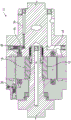
图1A是沿着根据本申请的示例的竖直线截取的图1的液压装置的截面图。1A is a cross-sectional view of the hydraulic device of FIG. 1 taken along a vertical line according to an example of the present application.
图1B是沿着根据本申请的示例的水平线截取的图1的液压装置的截面图。1B is a cross-sectional view of the hydraulic device of FIG. 1 taken along a horizontal line according to an example of the present application.
图2A是图1B的液压装置的一部分的截面图,示出了根据本申请的示例的液压装置在泵模式下的操作,在泵模式下,液压流体从压力象限传递到叶片台阶区域。2A is a cross-sectional view of a portion of the hydraulic device of FIG. IB illustrating operation of the hydraulic device according to an example of the present application in a pump mode in which hydraulic fluid is transferred from a pressure quadrant to a vane step area.
图2B是图1B的液压装置的一部分的截面图,示出了根据本申请的示例的液压装置在马达模式下的操作,在马达模式下,加压的液压流体通过提升阀从外部的端口传递到叶片台阶区域。2B is a cross-sectional view of a portion of the hydraulic device of FIG. 1B illustrating operation of the hydraulic device according to an example of the present application in a motor mode in which pressurized hydraulic fluid is delivered from an external port through a poppet valve to the blade step area.
图3和3A包括液压装置的部分的截面图,示出了根据本申请的示例的转子、环和阶梯式辊叶片。3 and 3A include cross-sectional views of portions of a hydraulic device showing rotors, rings, and stepped roller blades according to examples of the present application.
图4-6示出了图3和图3A的液压装置的移除多个阶梯式辊叶片的一部分,并示出了转子内的内部通道,转子内的内部通道用于使液压流体通过以用各种操作模式控制辊叶片的运动,各种操作模式包括抽吸操作模式、停顿操作模式和压力操作模式,如根据本申请的示例的三个辊叶片所示。Figures 4-6 show a portion of the hydraulic device of Figures 3 and 3A with the plurality of stepped roller blades removed and showing internal passages within the rotor for passage of hydraulic fluid for use with Various modes of operation control the movement of the roller blades, including a suction mode of operation, a standstill mode of operation, and a pressure mode of operation, as shown by the three roller blades according to the examples of the present application.
图7还示出了根据本申请的一个示例的图3和3A的液压装置的具有阶梯式辊叶片的一部分,阶梯式辊叶片的相对于环的运动通过设置在叶片下的液压流体被控制。7 also shows a portion of the hydraulic device of FIGS. 3 and 3A having stepped roller blades whose movement relative to the ring is controlled by hydraulic fluid disposed under the blades, according to one example of the present application.
图8A示出了根据本申请的示例的包括阶梯式叶片和辊的阶梯式辊叶片的第一透视图。8A shows a first perspective view of a stepped roller blade including a stepped blade and a roller according to an example of the present application.
图8B示出了根据本申请的示例的阶梯式辊叶片的第二透视图,该阶梯式辊叶片在其一部分中具有制动器。8B shows a second perspective view of a stepped roller blade having a brake in a portion thereof according to an example of the present application.
图9示出了根据本申请的示例的图8A的辊被移除的阶梯式辊叶片。FIG. 9 shows the stepped roller blades with the rollers of FIG. 8A removed, according to an example of the present application.
图10示出了具有以虚线示出的阶梯式叶片的阶梯式辊叶片,以示出根据本申请的示例的用于使润滑剂流到辊的内部通道。Figure 10 shows a stepped roller blade with stepped blades shown in phantom to illustrate internal passages for lubricant flow to the roller according to an example of the present application.
图11示出了根据本申请的示例的阶梯式叶片的辊腔,辊腔具有沿其延伸以使润滑剂围绕着辊流动的凹槽。11 illustrates a roll cavity of a stepped blade having grooves extending therealong to allow lubricant to flow around the roll, according to an example of the present application.
图12是根据本申请的示例的液压装置的一部分的透视图,示出了转子、没有环的阶梯式叶片,转子的多个部分以虚线示出以示出用于液压流体流动的内部通道,另外,转子可以分成多个部分。12 is a perspective view of a portion of a hydraulic device according to an example of the present application showing a rotor, stepped vanes without rings, portions of the rotor are shown in phantom to show internal passages for hydraulic fluid flow, In addition, the rotor can be divided into multiple parts.
图13是根据本申请的示例的图12的转子的一部分的放大视图,示出了可用于将阶梯式辊叶片锁定在缩回位置的球和致动机构。13 is an enlarged view of a portion of the rotor of FIG. 12 showing a ball and actuation mechanism that may be used to lock the stepped roller blades in a retracted position, according to an example of the present application.
图14示出了根据本申请的示例的液压装置,其中壳体的多个部分和其他部件被移除以示出输出轴和组装的盒,该盒包括前板和环。14 shows a hydraulic device according to an example of the present application with portions of the housing and other components removed to show the output shaft and the assembled cassette including the front plate and the ring.
图15-16A示出了根据本申请的示例的包括在图15中的以虚线示出的环,示出了便于液压流体流动的内部通道。Figures 15-16A illustrate the ring shown in phantom in Figure 15, illustrating internal passages that facilitate hydraulic fluid flow, according to an example of the present application.
图17示出了根据本申请的示例的液压装置,其中壳体的一些部分和其他部件被移除以示出设置为输出轴组件的一部分的推力轴承。17 shows a hydraulic device according to an example of the present application with portions of the housing and other components removed to show the thrust bearing provided as part of the output shaft assembly.
图18A和18B示出了根据本申请的示例的推力轴承的透视图。18A and 18B illustrate perspective views of thrust bearings according to examples of the present application.
图19A和19B示出了根据本申请的示例的推力轴承和前压板的横截面。19A and 19B illustrate cross-sections of thrust bearings and front pressure plates according to examples of the present application.
图20示出了根据本申请的示例的前压板的透视图。20 shows a perspective view of a front platen according to an example of the present application.
图21-25示出了在本申请的实验示例部分期间测试的叶片的各种构造。21-25 illustrate various configurations of blades tested during the experimental example portion of this application.
图26示出了使用图21-25的各种叶片构造在不同的操作条件下的实验结果的表格。Figure 26 shows a table of experimental results under different operating conditions using the various blade configurations of Figures 21-25.
具体实施方式Detailed ways
本申请涉及利用阶梯式叶片构造的辊叶片液压装置。此外,本申请涉及将液压装置与包括启动马达的其他部件组合使用的系统。本装置和系统的其他方面将被讨论或对于相关领域的普通技术人员而言将是显而易见的。The present application relates to roller blade hydraulics utilizing stepped blade configurations. Furthermore, the present application relates to systems that use hydraulics in combination with other components including a starter motor. Other aspects of the present apparatus and system will be discussed or will be apparent to those of ordinary skill in the relevant art.
图1-1B示出了用于液压泵送和/或扭矩传递的作为液压联接器的示例性液压装置10。如图1和1A所示,液压装置10包括可变叶片液压装置。关于叶片液压装置的构造和操作的其它信息可以在例如申请人拥有的美国专利申请公开文件2013/0067899A1和美国专利7,955,062、8,597,002和8,708,679中找到,并且通过引用而被纳入本文。1-1B illustrate an exemplary
如图1A所示,液压装置10可包括输入轴12,输出轴14,转子16,第一阶梯式叶片16A和第二阶梯式叶片16B,环18,前板20,后板22,壳体24第一入口26,第二入口28,第三入口30,一个或多个启动马达入口32,以及排放口/出口34。As shown in FIG. 1A , the
如图1A所示,输入轴12可以延伸到液压装置10中并且可以延伸到输出轴14附近。转子16可以与输入轴12连接以便旋转。环18可以至少部分地围绕转子16设置(例如,可以与转子16连接)。前板20可围绕输入轴12设置,并轴向邻近转子16和环18。后板22可设置在输出轴14周围或可包括输出轴14的一部分,并轴向邻近转子16和环18。壳体24(例如,中间主体、前壳体和后壳体)可以围绕所示的包括环18的各种部件设置。第一入口26可以包括壳体24中的端口,该端口可以另外由前板20、环18和转子16限定。第二入口28可包括壳体24中的端口,该端口可另外由前板20、环18和转子16限定。如将讨论和随后说明的那样,第一入口26可用于在泵操作模式期间接收液压流体。第二入口28可在马达操作模式期间使用。类似地,第三入口30可以由壳体24、输入轴12、环18和转子16限定,并且可以用于提供夹紧力以将阶梯式叶片16A和16B锁定在缩回位置。启动马达入口32可以由壳体24、输出轴14、环18和转子16限定,并且可以用于引导流动以在马达操作模式下将阶梯式叶片16A和16B推出。提供没有具体数量的各种其他控制端口以提供装置10的液压控制。提供排放口/出口34以接收来自壳体内的其他部件的诸如轴承的部件的液压流体的流动。As shown in FIG. 1A , the
转子16可设置成绕轴线(与输入轴12相同的转动轴线)旋转。如本文所用,术语“径向”和“轴向”是相对于沿输入轴12延伸的轴线描述的。如随后的图中所示,转子16可具有多个周向间隔开的狭槽。狭槽可以构造成在其中容纳多个叶片,多个叶片包括第一阶梯式叶片16A和第二阶梯式叶片16B。在一些情况下,多个阶梯式叶片(包括第一阶梯式叶片16A和第二阶梯式叶片16B)可构造成能够在缩回位置和延伸位置之间径向移动,在延伸位置处,多个阶梯式叶片操作引入至转子16附近(例如,在转子16和环18之间限定的腔中)的液压流体。在其他实施例中,阶梯式叶片16A,16B的位置可相对于转子16固定。The
环18和转子16可以与多个入口26、28、30和32选择性地连通,以允许液压流体进入转子16附近或从转子16附近通过(排出口/出口34)离开。如随后将进一步详细讨论的,转子16可包括叶片下方通道,一些叶片下方通道与每个阶梯式叶片的台阶连通以便于阶梯式叶片(例如,包括第一阶梯式叶片16A和第二阶梯式叶片16B)的到转子16内的缩回位置和从转子16内的缩回位置到达接触环18的延伸位置的运动。
输入轴12可以是扭矩源(例如发动机,马达等)。在某些情况下,需要启动马达模式。在这种情况下,可以使用一个或多个启动马达入口32。输出轴14可以通过锁定组件35保持静止,并且使用来自诸如蓄积器(图21)的源的能量加压的液压流体可以用于使阶梯式叶片延伸,从而使扭矩源发动。The
输出轴14可以联接到动力系。在操作中,环18可以限定与液压装置10的入口和排出压力流体连通的腔(也称为腔室)(如图3-7所示)。根据图1A图示的示例,包括转子16和输入轴10的旋转组构造成围绕腔内的轴线旋转(图3-7)。处于可变叶片构造的转子16可以限定多个狭槽,多个狭槽沿着转子的外部大致平行于轴线延伸,通向腔并且适于接收和保持包括第一叶片16A和第二叶片16B的多个叶片。各种示例可以包括设置在保持通道中的液压控制的保持器(随后在图13中示出),以将多个阶梯式叶片保持在叶片缩回操作模式中并且在叶片延伸操作模式中释放第一叶片,在叶片延伸操作模式中,多个叶片延伸以与环18相遇以操作液压流体。因此,在一些实施例中,包括第一阶梯式叶片16A和第二阶梯式叶片16B的多个阶梯式叶片可相对于转子16和环18径向移动。The
在各种示例中,输出轴14由于在叶片延伸操作模式下工作的液压流体而具有扭矩。操作模式可以例如通过经由入口/端口(例如,入口26、28、30、32中的一个或另一个端口)传输到液压装置10的流体信号以被控制。如前所述,这里讨论的概念也适用于固定的阶梯式叶片结构,在固定的阶梯式叶片结构中,阶梯式叶片相对于转子16具有固定高度。In various examples, the
在各种示例中,液压流体可包括进入和离开液压装置的油,乙二醇,水/乙二醇或其他液压流体中的任何一种。在一些示例中,流体可以流到单独的储存器或源和/或从单独的储存器或源流出。例如,来自蓄积器的加压流体可用于如上所述操作启动马达那样操作液压装置10。或者,一些示例使用较大的壳体,较大的壳体可容纳足够的流体以用于操作和冷却。在一些示例中,入口26、28、30和32可以不同地用于使多个阶梯式叶片与环18接合和脱离,并且相对于转子16驱动、(通过锁定机构)抑制并且释放多个阶梯式叶片。在美国专利申请公开文件No.2006/0133946中阐述了叶片缩回或释放的一个示例,美国专利申请公开文件No.2006/0133946通过引用而被纳入本文。多个阶梯式叶片的释放将导致液压装置10作为联接器、马达和/或液压泵的操作,如在一个或多个先前结合的参考文献中进一步详细讨论的。可以通过压力调节器、提升阀或其他已知方法来控制多个入口26、28、30、32和腔的液压。液压装置10中的压力控制可以通过例如控制平衡活塞来实现,如美国专利申请公开文件No.2013/00067899中所述。In various examples, the hydraulic fluid may include any of oil, glycol, water/glycol, or other hydraulic fluid entering and leaving the hydraulic device. In some examples, fluids may flow to and/or from separate reservoirs or sources. For example, pressurized fluid from the accumulator may be used to operate the
图1B示出了液压装置10沿另一平面的第二横截面。因此,图1B示出了先前关于图1A所讨论的许多部件,许多部件包括输入轴12,输出轴14,转子16,第三阶梯式叶片16C和第四阶梯式叶片16D,环18,前板20,壳体24和一个或多个启动马达入口32。FIG. 1B shows a second cross-section of the
图1B示出了一个或多个启动马达入口32可包括通道34,通道34穿过输出轴14并与环18和转子16连通,以通过将阶梯式叶片从转子16向外推动以接触如前所述的环18而便于启动马达操作模式。图1B还进一步示出了一个或多个提升阀36,一个或多个提升阀36可用于一些实施例中以调节液压装置10内的液压流体流动,包括停止或限制流向叶片台阶的流动(随后示出)。控制入口38也在图1B中示出。FIG. 1B shows that one or more
图2A和2B示出了液压装置10的泵操作模式(图3A)和马达操作模式(图3B)期间的液压流体和其他部件布置。图2A和2B中移除了壳体。2A and 2B illustrate hydraulic fluid and other component arrangements during a pump mode of operation ( FIG. 3A ) and a motor mode of operation ( FIG. 3B ) of the
图2A示出了泵模式,在泵模式中,液压流体从腔(在转子16和环18之间限定并且随后进一步示出)的压力象限传递到叶片台阶区域(再次示出并随后讨论)。如前所述,液压流体流向叶片台阶区域的流动可以使阶梯式叶片相对于转子16延伸和移动。液压流体流动用箭头示出并穿过一个或多个提升阀36。一个或多个提升阀36通过来自压力象限的液压流动从所示的位置被推动远离环18和转子16(即,液压流体的压力克服弹簧40的在一个或多个提升阀36上的偏压)。根据一些示例,液压流体可以通过第一推力轴承42(随后进一步示出)传递到叶片台阶。如前所述,在台阶式叶片缩回进入转子16中的狭槽时,叶片台阶区域的体积减小,并且液压流体通过和/或穿过一个或多个提升阀36流回以排出。这种流动可以通过直径只有不到一毫米到几毫米的通道(未示出)。Figure 2A shows a pump mode in which hydraulic fluid is transferred from the pressure quadrant of the cavity (defined between the
图2B示出了液压装置10的马达操作模式,例如先前描述的启动马达操作模式。如箭头所示,来自外源(例如,蓄积器等)的液压流体可以通过通道34传输,以便通过克服一个或多个第二提升阀44(位于通道34中)上的弹簧偏压来移动一个或多个第二提升阀44。这允许液压流体流过或经过第二推力轴承46到叶片台阶区域。如前所述,液压流体流向叶片台阶区域的流动可以使阶梯式叶片相对于转子16延伸和移动。应该注意,在马达操作模式中,一个或多个提升阀36(或另一装置)可用于阻止来自腔的压力象限(有时称为腔室)的液压流体流动。在先前参考图2A描述的泵操作模式期间不是这种情况。如前所述,在马达模式中,在将阶梯式叶片缩回到转子16中的狭槽中时,叶片台阶区域的体积减小并且液压流体流过和/或穿过一个或多个提升阀36以排出,如先前关于图2A描述的。FIG. 2B shows a motor mode of operation of the
图3和3A示出了具有阶梯式叶片50的液压装置10以及阶梯式叶片50相对于转子16和环18的布置。如图3和3A所示,环18的横截面可以具有非圆形的内部形状,而转子16的横截面可以是圆形的。因此,阶梯式叶片50可相对于转子16延伸各种距离,以接触环18的内表面52。图3和3A还示出了叶片台阶区域53,叶片台阶区域53用于每个转子16和阶梯式叶片50的组合。然而,由于环18相对于转子16的几何形状,叶片台阶区域53的尺寸(体积)将对于转子16和阶梯式叶片50的每个组合而不同(环18的横截面为非圆形内部形状,而转子16的横截面可以是圆形的)。3 and 3A illustrate the
如图3和3A所示,腔54可以限定在转子16,环18,前板20和后板(未示出)之间。腔54的几何形状可以随着转子16的旋转和阶梯式叶片50的移动而变化(例如,阶梯式叶片50从转子16延伸和缩回到转子16中)。如前所述,多个端口(如图4-6所示)由前板20,后板22(未示出),环18,转子16(包括多个叶片)限定。如图3和3A所示,腔54可构造成当多个阶梯式叶片50经过这些端口时允许液压流体径向地设置在转子16的至少一部分的外侧。在图3和3A的示例中,腔54可沿轴向延伸,并且可由环18的内表面限定,并且由转子16限定。As shown in Figures 3 and 3A,
图4-6示出了一些阶梯式叶片50以及转子16和环18。图4、5和6还示出了抽吸端口56和出口端口58(如上所述)。如操作标准指示,这些端口允许液压流体进入腔54或从腔54离开。在腔54内,液压流体可以由阶梯式叶片50操作,如前所述。4-6 show some of the stepped
图4-6还示出了压力区域60和抽吸区域62。这些区域60、62还可以是叶片下方区域60A、60B和62A、62B(即,穿过前板或后板和/或转子16),当转子16旋转时叶片下方区域60A、60B和62A、62B选择性地与叶片台阶区域53连通。这种叶片下方区域60A、60B和62A、62和/或64可以包括具有与抽吸端口56和出口端口58的压力相似或不同的压力的端口。可以在叶片下方区域64上保持出口压力以进行转子16的完全旋转,以在阶梯式叶片50上保持向外的恒力。通过使用叶片下方区域60A、60B和62A、62B,可以另外改变阶梯式叶片50上的这种力。4-6 also show a
图4示出了当至少两个阶梯式叶片50正在经历抽吸过程(即,在抽吸区域62和62A中)时,叶片下方区域64可以通向出口压力并且阶梯式叶片区域53通向抽吸压力。阶梯式叶片区域53通过与区域62、62A和62B连通的端口(仅识别端口56)打开以便抽吸。在抽吸过程、停顿过程和压力过程期间,每个阶梯式叶片的外径向部分(在端口56的区域中)可以作为标准叶片泵操作,如图4-6所示。Figure 4 shows that when at least two stepped
图4A示出了与出口端口58相邻的阶梯式叶片50的外径向部分的一部分的放大图。由于每个阶梯式叶片50包括在辊叶片上没有前缘的辊叶片,叶片安装在叶片主体上。在出口端口58的区域中,叶片受到高压楔力(由箭头指示)。为了抵消该力,对应的向外力(由通过叶片下方区域传递到阶梯式叶片区域53的液压流体施加)的工作区域必须超过楔力。因此,阶梯式叶片区域53可以用作泵送腔室。当阶梯式叶片50缩回时,液压流体可被泵送至压力(例如,经由出口端口58和/或其他端口),并且当阶梯式叶片50延伸时,阶梯式叶片区域53可被抽吸的液压流体填充(例如,通过抽吸端口56和/或其他端口)。FIG. 4A shows an enlarged view of a portion of the outer radial portion of the stepped
图5示出了当至少两个阶梯式叶片50经历停顿时(阶梯式叶片区域53可以分别在区域62A和60B中),叶片下方区域64可以通向出口压力并且阶梯式叶片区域53可以关闭。5 shows that when at least two stepped
图6示出了当至少两个阶梯式叶片50正在经历压力过程(即,在压力区域60和60A中)时,叶片下方区域64可以通向出口压力并且阶梯式叶片区域53也通向出口压力。阶梯式叶片区域53可以通过与区域60、60A和60B连通的端口通向出口压力(在图6中仅识别端口58)。Figure 6 shows that when at least two stepped
图7显示了参考图4-6描述的(压力和抽吸)过程,在图4-6中,液压流体66被移动到阶梯式叶片区域53或从阶梯式叶片区域53移出,以在相应的阶梯式叶片50上提供所需的向外的力,使得在适当大小的力被施加在每个辊和内表面52之间的情况下,这种叶片的辊保持与环18的内表面52接触。如图7所示,阶梯式叶片区域53中的液压流体66的体积将随着转子16相对于环18的旋转而改变。如图7所示,总是向叶片下方区域64供应液压流体66。Figure 7 shows the (pressure and suction) process described with reference to Figures 4-6, in which
图8A和8B示出了根据一个实施例的阶梯式叶片50和辊68。图9示出了阶梯式叶片50,其中辊被移除以示出辊腔69。每个阶梯式叶片50具有构造成形成台阶72的主体70。根据一些实施例,台阶72可具有基本上为总叶片宽度WT的55%的宽度WS。这意味着如果总叶片宽度WT是4.8mm,则台阶72的宽度WS将是2.64mm。然而,根据其他实施例,宽度WS可以在总叶片宽度WT的45%和65%之间。如前所述,辊叶片设计需要增加叶片上的向外的力以补偿在抽吸区域和出口压力区域中通过液压流体的辊的动态的向内的力。本阶梯式叶片设计允许用于加压液压流体的总叶片宽度WT的约55%的较大表面积在阶梯式叶片50上产生向外的径向力,以便保持辊68与环的内表面的接触。8A and 8B illustrate stepped
图8B示出了可以在主体70的后表面76上使用的制动器74。制动器74可以与锁定机构(参考图13描述和示出)结合使用,以将阶梯式叶片保持在转子内,如操作标准所指示。FIG. 8B shows the
图10和11示出了内部通道78A、78B和凹槽80A、80B、80C和80D,内部通道78A、78B和凹槽80A、80B、80C和80D可以将液压流体传递到辊68(图11中未示出)以用作润滑剂。根据一些实施例,液压流体在辊68上产生润滑膜,该润滑膜可构造成在辊腔69内旋转(图11)。FIGS. 10 and 11 show
图12示出了设置在液压装置10的转子16内的阶梯式叶片50。图12还示出了转子16内的内部通道,内部通道可用于使液压流体流动至例如如前所述的叶片台阶区域53。图12另外示出了根据一些实施例的转子16可以分段成两个或更多个部分81A和81B。类似地,根据一些实施例,阶梯式叶片50和/或辊68可以被分段,以便形成多个部分。FIG. 12 shows stepped
图13示出了转子16的部分81A和图12中的阶梯式叶片50,并删除了额外的部分。图13另外示出了锁定机构82,锁定机构82包括致动器84和球86。球86可由致动器84移动,以与阶梯式叶片50的后表面76上的制动器74接合,以将阶梯式叶片50保持在转子16内,如图13所示。根据一个示例,液压引导信号可以被发送到致动器84(例如,锥形推销),致动器84又迫使球86进入制动器74中。这防止了阶梯式叶片50跟随环的内表面的轮廓并防止产生泵送腔室。所示的锁定/保持位置(其中阶梯式叶片50缩回到转子16中)可以有效地被认为是具有非常低的寄生损失和零流量的中性位置。FIG. 13 shows
图14示出了没有如前所述的壳体和输入轴的液压装置10。在图14中,环18上的抽吸端口88示出为前板20的抽吸端口90。后板22还示出为具有抽吸端口92。图14示出了可用于液压调节器、用于动力分配的液压流体流出和用于其他目的的各种其他端口。根据一个示例,液压装置10可以被配置为动力分配变速器,泵,马达,启动马达,并且可以根据如前所述的各种操作模式用于液压混合动力再生。对于泵操作模式,输出轴可以被有效地中和,并且环18可以保持固定在壳体中。Figure 14 shows the
图15-16B更详细地示出了环18,环18包括内表面52、抽吸端口和通道94,以及压力出口和通道96。这种抽吸端口和通道94以及压力出口和通道96的确切数量和尺寸可以根据操作标准和其他因素而变化。FIGS. 15-16B show the
图17-18B示出了如前所述的第一推力轴承42或第二推力轴承46中的一个。图17示出了安装在后板22内的第二推力轴承46。图18A和18B从不同的角度示出了第一推力轴承42或第二推力轴承46的构造。17-18B illustrate one of the first thrust bearing 42 or the second thrust bearing 46 as previously described. FIG. 17 shows the second thrust bearing 46 mounted within the
推力轴承设计可以允许从转子到前板20和后板22(图17中未示出前板20)的非常紧密的公差。这种紧密的公差可以减少泄漏并减少部件之间的摩擦运动的情况。这种紧密的公差还允许压力液压流体进给到如前所述的叶片台阶区域,以提供向外的径向力以保持辊与环接触。The thrust bearing design may allow for very tight tolerances from the rotor to the
图18A示出了推力轴承42、46的与转子16(未示出)接合的部分。该面98可在其中具有环形凹槽100,环形凹槽100允许液压流体流向叶片台阶区域。图18B示出了推力轴承42、46的相反面102,相反面102可面向板20或22。面102可包括允许油流到环形凹槽的狭槽104。还提供了其他特征,例如一个或多个轴承销孔106。Figure 18A shows the portions of the
图19A和19B示出了设置在前板20内并由前板20承载的第一推力轴承42。图19A和19B还通过两个单独的横截面进一步详细示出了前板20。前板20可包括如前所述的端口和通道,通道包括通道107,通道107构造成使液压流体在抽吸中流动到阶梯式叶片的底部,如图19A所示。图19B示出了前板20可以具有第二通道108,第二通道108用于使液压流体从压力区域(先前描述和示出)流到叶片台阶区域。根据一些实施例,这种第二通道108可以通向推力轴承42,这允许液压流体穿过并经过推力轴承42到达叶片台阶区域。19A and 19B illustrate the first thrust bearing 42 disposed within and carried by the
图20示出了没有装配到其上的推力轴承42(图19A和19B)的前板20的示例。图20示出了用于如前所述的阶梯式叶片操作的压力供给孔和凹槽。特别地,前板20可以具有面110。面110可以在出口腔112的区域中成型,以防止辊从叶片主体滑动。面110可包括凹槽112,以用于促进液压流体流动到叶片台阶区域,如前所述和所示。另外,一个或多个通道114可以设置在前板20中,以便于液压流体流动到如前所述和所示的中间区域64。尽管未在图20中示出,但是后板22可以具有与前板20类似的结构,并且可以包括诸如凹槽112和一个或多个通道114的特征。FIG. 20 shows an example of the
所公开的液压装置可以允许诸如减小动力系经历的峰值瞬态力,降低的液压噪声,更高的燃料效率,减少的排放以及其他益处的益处。The disclosed hydraulics may allow for benefits such as reduced peak transient forces experienced by the powertrain, reduced hydraulic noise, greater fuel efficiency, reduced emissions, and other benefits.
可以使用本文未参考附图具体讨论的其他示例。所公开的装置适用于各种类型的车辆,例如土方设备(例如,轮式装载机,小型装载机,反铲装载机,自卸卡车,起重机卡车,运输搅拌机等),废物回收车辆,船用车辆,工业设备(例如,农业设备),私人车辆,公共交通工具和商用道路车辆(例如,重型公路卡车,半卡车等)。所公开的液压装置还可以用于其中装置将是固定的其他应用中(例如,在风力收集和生产和/或其他类型的能量收集和生产的应用中)。Other examples not specifically discussed herein with reference to the figures may be used. The disclosed apparatus is suitable for use in various types of vehicles, such as earth moving equipment (eg, wheel loaders, mini loaders, backhoe loaders, dump trucks, crane trucks, transport mixers, etc.), waste recycling vehicles, marine vehicles , industrial equipment (eg, agricultural equipment), personal vehicles, public transportation, and commercial road vehicles (eg, heavy-duty road trucks, semi-trucks, etc.). The disclosed hydraulic devices may also be used in other applications where the device will be stationary (eg, in wind harvesting and production and/or other types of energy harvesting and production applications).
尽管图1-20中示出了并且特别如上所述装置的特定构造,但是预期落入权利要求范围内的其他设计。While specific configurations of the device are shown in Figures 1-20 and particularly described above, other designs are contemplated that fall within the scope of the claims.
以上详细描述包括对附图的参考,附图形成详细描述的一部分。附图通过图示的方式示出了可以实施本发明的具体实施例。这些实施例在本文中也称为“示例”。这些示例可以包括除了示出或描述的那些元件之外的元件。然而,本发明人还考虑了仅提供所示或所述的那些元件的实例。此外,本发明人还考虑使用关于特定示例(或其一个或多个方面)或关于在此示出或描述的其他示例(或其一个或多个方面)示出或描述(或其一个或多个方面)的那些元件的任何组合或排列的示例。The foregoing detailed description includes references to the accompanying drawings, which form a part of the detailed description. The drawings show, by way of illustration, specific embodiments in which the invention may be practiced. These embodiments are also referred to herein as "examples." These examples may include elements in addition to those shown or described. However, the inventors also contemplate examples that provide only those elements shown or described. In addition, the inventors contemplate using what is shown or described (or one or more of them) with respect to a particular example (or one or more aspects thereof) or with respect to other examples (or one or more aspects thereof) shown or described herein. aspects) are examples of any combination or permutation of those elements.
如果本文件与通过引用并入的任何文件之间的使用不一致,则以本文件中的用法为准。本文中,术语“一个”或“一”在专利文献中是常见的,包括一个或多于一个,独立于“至少一个”或“一个或多个”的任何其他实例或用法。本文中,除非另有说明表示,术语“或”用于表示非排他性的或者,使得“A或B”包括“A但不是B”,“B但不是A”和“A和B”。在本文中,术语“包括”和“其中”用作相应术语“包括”和“其中”的普通英语等同物。此外,在以下权利要求中,术语“包括”和“包含”是开放式的,即包括除了在权利要求中的这一术语之后列出的元件之外的元件的系统,装置,物品,组合物,配方或过程仍被认为属于该权利要求的范围。此外,在以下权利要求中,术语“第一”,“第二,“和”第三“等仅被用作标签,并不旨在对其对象施加数字要求。In the event of inconsistency in usage between this document and any document incorporated by reference, the usage in this document shall control. As used herein, the terms "a" or "an" are commonly used in patent literature to include one or more than one, independent of any other instance or usage of "at least one" or "one or more." Herein, unless indicated otherwise, the term "or" is used to mean a non-exclusive alternative such that "A or B" includes "A but not B", "B but not A" and "A and B". In this document, the terms "including" and "wherein" are used as the plain English equivalents of the corresponding terms "including" and "wherein." Furthermore, in the following claims, the terms "comprising" and "comprising" are open ended, ie a system, apparatus, article, composition comprising elements other than the elements listed after this term in a claim , the formulation or process is still considered to fall within the scope of the claim. Furthermore, in the following claims, the terms "first," "second," and "third," etc. are used merely as labels, and are not intended to impose numerical requirements on their objects.
以上描述旨在是说明性的而非限制性的。例如,上述示例(或其一个或多个方面)可以彼此组合使用。在阅读以上描述之后,例如本领域普通技术人员可以使用其他实施例。提供摘要以符合37C.F.R.§1.72(b),允许读者快速确定技术公开的性质。所认为的理解是,它不会用于解释或限制权利要求的范围或含义。而且,在以上详细描述中,可以将各种特征组合在一起以简化本公开。这不应被解释为意图未保护的公开特征对于任何权利要求是必不可少的。相反,发明主题可以在于少于特定公开实施例的所有特征的范围内。因此,以下权利要求作为示例或实施例结合到具体实施方式中,其中每个权利要求自身作为单独的实施例,并且可以预期这些实施例可以以各种组合或排列彼此组合。应参考所附权利要求以及这些权利要求所赋予的等同物的全部范围来确定本发明的范围。The above description is intended to be illustrative and not restrictive. For example, the above examples (or one or more aspects thereof) may be used in combination with each other. After reading the above description, for example, one of ordinary skill in the art may use other embodiments. The Abstract is provided to comply with 37 C.F.R. §1.72(b), allowing the reader to quickly determine the nature of the technical disclosure. It is to be understood that it will not be used to interpret or limit the scope or meaning of the claims. Furthermore, in the above Detailed Description, various features may be grouped together to simplify the disclosure. This should not be construed as an intention that an unprotected disclosed feature is essential to any claim. Rather, inventive subject matter may lie in less than all features of a particular disclosed embodiment. Thus, the following claims are hereby incorporated into the Detailed Description by way of example or embodiment, with each claim standing on its own as a separate embodiment, and it is contemplated that these embodiments may be combined with each other in various combinations or permutations. The scope of the invention should be determined with reference to the appended claims, along with the full scope of equivalents to which such claims are entitled.
为了进一步说明本文公开的系统和/或装置,提供以下非限制性实例:To further illustrate the systems and/or devices disclosed herein, the following non-limiting examples are provided:
在示例1中,一种液压装置,该液压装置可选地包括:转子,该转子设置成绕轴线旋转;多个叶片,每个叶片包括叶片台阶,多个叶片中的每个叶片可相对于转子在缩回位置和延伸位置之间移动,在延伸位置处,多个叶片对引入至转子附近的液压流体作功;辊,该辊安装在多个叶片中的每个叶片的尖端上;和至少部分地围绕转子设置的环,转子包括一个或多个通道,一个或多个通道用于使液压流体进入或离开与叶片台阶相邻并至少由转子和叶片台阶限定的区域。In Example 1, a hydraulic device optionally comprising: a rotor configured to rotate about an axis; a plurality of vanes, each vane including a vane step, each vane of the plurality of vanes operative relative to the rotor moves between a retracted position and an extended position where the plurality of vanes perform work on hydraulic fluid introduced into the vicinity of the rotor; a roller mounted on a tip of each of the plurality of vanes; and A ring disposed at least partially around the rotor, the rotor including one or more passages for passing hydraulic fluid into or out of an area adjacent to the vane steps and defined at least by the rotor and the vane steps.
在示例2中,根据示例1所述的液压装置还可选地包括:第一推力轴承,该第一推力轴承设置在转子的第一轴向端附近;和第二推力轴承,该第二推力轴承设置在转子的第二轴向端附近,第二轴向端与第一轴向端相反;其中,液压流体穿过第一推力轴承和第二推力轴承中的至少一个,以与转子中的一个或多个通道连通。In Example 2, the hydraulic device of Example 1 further optionally includes: a first thrust bearing disposed near the first axial end of the rotor; and a second thrust bearing, the second thrust bearing The bearing is disposed near a second axial end of the rotor, the second axial end being opposite the first axial end; wherein hydraulic fluid passes through at least one of the first thrust bearing and the second thrust bearing to communicate with the rotor in the rotor One or more channels are connected.
在示例3中,根据示例2所述的液压装置还可选地包括:第一板,该第一板设置在转子的第一轴向端附近并且构造成至少部分地容纳第一推力轴承,第一板限定并至少具有第一通道,第一通道构造成在所述环和所述第一推力轴承之间传输所述液压流体;和第二板,该第二板设置在转子的第二轴向端附近并且构造成至少部分地容纳第二推力轴承,第二板至少限定第二通道,第二通道构造成将液压流体传输到第二推力轴承。In Example 3, the hydraulic device of Example 2 further optionally includes a first plate disposed near the first axial end of the rotor and configured to at least partially receive the first thrust bearing, the first plate A plate defines and has at least a first passageway configured to transmit the hydraulic fluid between the ring and the first thrust bearing; and a second plate disposed on the second shaft of the rotor Proximate the end and configured to at least partially receive the second thrust bearing, the second plate defines at least a second passage configured to transmit hydraulic fluid to the second thrust bearing.
在示例4中,根据示例3所述的液压装置还可选地包括至少一个提升阀,该至少一个提升阀设置在第一板和第二板中的一个或两个内,以调节液压流体的流动。In Example 4, the hydraulic device of Example 3 further optionally includes at least one poppet valve disposed in one or both of the first plate and the second plate to regulate the flow of hydraulic fluid flow.
在示例5中,根据示例3所述的液压装置,其中,第一板、第二板和转子中的一个或多个可以可选地限定叶片下方区域,叶片下方区域构造成将液压流体供应到多个叶片中的每个叶片的径向内部。In Example 5, the hydraulic device of Example 3, wherein one or more of the first plate, the second plate, and the rotor can optionally define an under-vane region configured to supply hydraulic fluid to the the radially inner portion of each vane of the plurality of vanes.
在示例6中,根据示例1-5中的一项或任一组合所述的液压装置,其中,多个叶片中的至少一个可任选地包括从叶片台阶延伸到辊下方的尖端的通道。In Example 6, the hydraulic device of one or any combination of Examples 1-5, wherein at least one of the plurality of vanes optionally includes a channel extending from the vane step to a tip below the roller.
在示例7中,根据示例6所述的液压装置,其中,辊可以可选地构造成相对于叶片在液压流体的膜上旋转。In Example 7, the hydraulic device of Example 6, wherein the rollers may optionally be configured to rotate relative to the vanes on the film of hydraulic fluid.
在示例8中,根据示例1-7中任一项或任何组合所述的液压装置,其中,叶片台阶的宽度可任选地包括多个叶片中的每个叶片的总宽度的45%至65%之间的宽度。In Example 8, the hydraulic device of any one or any combination of examples 1-7, wherein the width of the vane step can optionally include 45% to 65% of the total width of each vane of the plurality of vanes The width between %.
在示例9中,根据示例8所述的液压装置,其中,叶片台阶的宽度可任选地包括总宽度的大致55%。In Example 9, the hydraulic device of Example 8, wherein the width of the vane step optionally includes approximately 55% of the overall width.
在示例10中,系统可以可选地包括:液压装置,该液压装置可选地包括:转子,该转子设置成绕轴线旋转;多个叶片,每个叶片包括叶片台阶,多个叶片中的每个叶片可相对于转子在缩回位置和延伸位置之间移动,在延伸位置处,多个叶片对引入至转子附近的液压流体作功;辊,该辊安装在多个叶片中的每个叶片的尖端上;和至少部分地围绕转子设置的环,转子包括一个或多个通道,一个或多个通道用于使液压流体进入或离开与叶片台阶相邻并至少由转子和叶片台阶限定的区域;和蓄积器,该蓄积器与液压装置流体连通以向液压装置供应液压流体,液压流体将多个叶片中的一个或多个叶片延伸至转子外并抵靠环,使得液压装置可作为启动马达操作。In Example 10, the system may optionally include a hydraulic device, the hydraulic device optionally including: a rotor configured to rotate about an axis; a plurality of vanes, each vane including a vane step, each of the plurality of vanes a plurality of vanes are movable relative to the rotor between a retracted position, where the plurality of vanes perform work on hydraulic fluid introduced into the vicinity of the rotor, and an extended position; a roller mounted to each vane of the plurality of vanes and a ring disposed at least partially around the rotor, the rotor including one or more passages for allowing hydraulic fluid to enter or leave the area adjacent to the vane steps and defined at least by the rotor and the vane steps and an accumulator in fluid communication with the hydraulic device to supply hydraulic fluid to the hydraulic device, the hydraulic fluid extending one or more of the plurality of vanes out of the rotor and against the ring so that the hydraulic device can act as a starter motor operate.
在示例11中,根据示例10所述的系统,其中,所述液压装置还可选地包括:第一推力轴承,该第一推力轴承设置在转子的第一轴向端附近;和第二推力轴承,该第二推力轴承设置在转子的第二轴向端附近,第二轴向端与第一轴向端相反;其中,液压流体穿过第一推力轴承和第二推力轴承中的至少一个,以与转子中的一个或多个通道连通。In Example 11, the system of Example 10, wherein the hydraulic device further optionally includes: a first thrust bearing disposed near the first axial end of the rotor; and a second thrust a bearing disposed near a second axial end of the rotor opposite the first axial end; wherein hydraulic fluid passes through at least one of the first thrust bearing and the second thrust bearing , to communicate with one or more channels in the rotor.
在示例12中,根据示例11所述的系统,其中,所述液压装置还可选地包括:第一板,该第一板设置在转子的第一轴向端附近并且构造成至少部分地容纳第一推力轴承,第一板限定并至少具有第一通道,第一通道构造成在所述环和所述第一推力轴承之间传输所述液压流体;和第二板,该第二板设置在转子的第二轴向端附近并且构造成至少部分地容纳第二推力轴承,第二板至少限定第二通道,第二通道构造成将液压流体传输到第二推力轴承。In Example 12, the system of Example 11, wherein the hydraulic device further optionally includes a first plate disposed adjacent the first axial end of the rotor and configured to at least partially receive a first thrust bearing, a first plate defining and having at least a first passage configured to transmit the hydraulic fluid between the ring and the first thrust bearing; and a second plate disposed Proximate the second axial end of the rotor and configured to at least partially accommodate the second thrust bearing, the second plate defines at least a second passage configured to transmit hydraulic fluid to the second thrust bearing.
在示例13中,根据示例12所述的系统,其中,所述液压装置还可选地包括至少一个提升阀,该至少一个提升阀设置在第一板和第二板中的一个或两个内,以调节液压流体的流动。In Example 13, the system of Example 12, wherein the hydraulic device further optionally includes at least one poppet valve disposed in one or both of the first plate and the second plate , to regulate the flow of hydraulic fluid.
在示例13中,根据示例12所述的系统,其中,第一板、第二板和转子中的一个或多个可以可选地限定叶片下方区域,叶片下方区域构造成将液压流体供应到多个叶片中的每个叶片的径向内部。In Example 13, the system of Example 12, wherein one or more of the first plate, the second plate, and the rotor can optionally define an under-vane region configured to supply hydraulic fluid to multiple the radially inner portion of each of the blades.
在示例14中,根据示例10-14中的一项或任一组合所述的系统,其中,多个叶片中的至少一个包括从叶片台阶延伸到辊下方的尖端的通道。In Example 14, the system of one or any combination of Examples 10-14, wherein at least one of the plurality of vanes includes a channel extending from the vane step to a tip below the roller.
在示例16中,根据示例15所述的系统,其中,辊可以可选地构造成相对于叶片在液压流体的膜上旋转。In Example 16, the system of Example 15, wherein the rollers may optionally be configured to rotate relative to the vanes on the film of hydraulic fluid.
在示例17中,根据示例10-16中的任一项或任一组合所述的系统,其中,叶片台阶的宽度可任选地包括多个叶片中的每个叶片的总宽度的45%至65%之间的宽度。In Example 17, the system of any one or any combination of Examples 10-16, wherein the width of the vane step can optionally include 45% to 45% of the total width of each vane in the plurality of vanes to Width between 65%.
在示例18中,根据权利要求17所述的系统,其中,叶片台阶的宽度可任选地包括总宽度的大致55%。In Example 18, the system of
在示例19中,一种液压装置,该液压装置可选地包括:转子,该转子设置成绕轴线旋转;多个叶片,每个叶片包括叶片台阶,多个叶片中的每个叶片可相对于转子在缩回位置和延伸位置之间移动,在延伸位置处,多个叶片对引入至转子附近的液压流体作功;辊,该辊安装在多个叶片中的每个叶片的尖端上;和至少部分地围绕转子设置的环,转子包括一个或多个通道,一个或多个通道用于使液压流体进入或离开与叶片台阶相邻并至少由转子和叶片台阶限定的区域;第一推力轴承,该第一推力轴承设置在转子的第一轴向端附近;和第二推力轴承,该第二推力轴承设置在转子的第二轴向端附近,第二轴向端与第一轴向端相反;其中,液压流体穿过第一推力轴承和第二推力轴承中的至少一个,以与转子中的一个或多个通道连通。In Example 19, a hydraulic device optionally comprising: a rotor configured to rotate about an axis; a plurality of vanes, each vane including a vane step, each vane of the plurality of vanes operative relative to the rotor moves between a retracted position and an extended position where the plurality of vanes perform work on hydraulic fluid introduced into the vicinity of the rotor; a roller mounted on a tip of each of the plurality of vanes; and a ring disposed at least partially around the rotor, the rotor including one or more passages for the passage of hydraulic fluid into or out of an area adjacent to the vane steps and defined at least by the rotor and the vane steps; a first thrust bearing , the first thrust bearing is provided near the first axial end of the rotor; and the second thrust bearing is provided near the second axial end of the rotor, the second axial end being connected to the first axial end Rather; wherein the hydraulic fluid passes through at least one of the first thrust bearing and the second thrust bearing to communicate with one or more passages in the rotor.
在示例20中,根据示例19所述的液压装置还包括:第一板,该第一板设置在转子的第一轴向端附近并且构造成至少部分地容纳第一推力轴承,第一板限定并至少具有第一通道,第一通道构造成在所述环和所述第一推力轴承之间传输所述液压流体;和第二板,该第二板设置在转子的第二轴向端附近并且构造成至少部分地容纳第二推力轴承,第二板至少限定第二通道,第二通道构造成将液压流体传输到第二推力轴承。In Example 20, the hydraulic device of Example 19 further includes a first plate disposed adjacent the first axial end of the rotor and configured to at least partially receive the first thrust bearing, the first plate defining and has at least a first passageway configured to transmit the hydraulic fluid between the ring and the first thrust bearing; and a second plate disposed adjacent the second axial end of the rotor And configured to at least partially accommodate the second thrust bearing, the second plate defines at least a second passage configured to transmit hydraulic fluid to the second thrust bearing.
在示例21中,根据示例20所述的液压装置进一步包括,至少一个提升阀,该至少一个提升阀设置在第一板和第二板中的一个或两个内,以调节液压流体的流动。In Example 21, the hydraulic device of Example 20 further includes at least one poppet valve disposed in one or both of the first plate and the second plate to regulate the flow of hydraulic fluid.
在示例22中,根据示例20所述的液压装置,其中,第一板、第二板和转子中的一个或多个可以可选地限定叶片下方区域,叶片下方区域构造成将液压流体供应到多个叶片中的每个叶片的径向内部。In Example 22, the hydraulic device of Example 20, wherein one or more of the first plate, the second plate, and the rotor can optionally define an under-vane region configured to supply hydraulic fluid to the radially inner portion of each vane of the plurality of vanes.
在示例23中,根据示例19-22中的一项或任一组合所述的液压装置,其中,多个叶片中的至少一个可任选地包括从叶片台阶延伸到辊下方的尖端的通道。In Example 23, the hydraulic device of one or any combination of Examples 19-22, wherein at least one of the plurality of vanes optionally includes a channel extending from the vane step to a tip below the roller.
在示例24中,根据示例23所述的液压装置,其中,辊可以可选地构造成相对于叶片在液压流体的膜上旋转。In Example 24, the hydraulic device of Example 23, wherein the rollers may optionally be configured to rotate relative to the vanes on the film of hydraulic fluid.
在示例25中,根据示例19-24中任一项或任何组合所述的液压装置,其中,叶片台阶的宽度可任选地包括多个叶片中的每个叶片的总宽度的45%至65%之间的宽度。In Example 25, the hydraulic device of any one or any combination of examples 19-24, wherein the width of the vane steps can optionally include 45% to 65% of the total width of each vane of the plurality of vanes The width between %.
在示例26中,根据示例25所述的液压装置,其中,叶片台阶的宽度可任选地包括总宽度的大致55%。In Example 26, the hydraulic device of Example 25, wherein the width of the vane steps optionally includes approximately 55% of the overall width.
在示例27中,根据示例1-26中的任何一项或任一组合所述的装置和/或系统可以可选地被配置为使得所述的所有元件或选项可供使用或选择。In Example 27, an apparatus and/or system according to any one or any combination of Examples 1-26 may optionally be configured such that all of the elements or options described are available or selected.
实验示例Experimental example
通过实验测试了叶片的各种构造。这种叶片的横截面结构如图21-25所示。“1类”叶片如图21所示。“2类”叶片如图22所示。“3类”叶片如图23所示。“4类”叶片如图24所示。“5类”叶片如图25所示。每个叶片的长度为55.66mm,但叶片的其他尺寸根据类型而变化,尺寸在图21-25中以mm表示。Various configurations of the blade were tested experimentally. The cross-sectional structure of such a blade is shown in Figures 21-25. "
如图26所示的表1列出了在各种条件下的实验结果。如表1所示,只有2类(阶梯式叶片)和5类能够通过测试而不会失败。测试标准包括在多个叶片下方压力(3000、3500和4500psi)下进行的测试,在多个马达RPM(2000和2500)下进行的测试,并使用最大环直径94.7mm进行的测试。根据以下规格使用针辊和保持架组件:Table 1, shown in Figure 26, lists the experimental results under various conditions. As shown in Table 1, only categories 2 (stepped blades) and 5 were able to pass the test without failing. Test criteria included tests at multiple under-blade pressures (3000, 3500 and 4500 psi), at multiple motor RPMs (2000 and 2500), and using a maximum ring diameter of 94.7 mm. Use the needle roller and cage assembly according to the following specifications:
类型:K90×98×30Type: K90×98×30
辊编号:44Roll Number: 44
基本动态额定载荷:64.4KNBasic dynamic load rating: 64.4KN
基本静态额定载荷:173KNBasic static load rating: 173KN
疲劳载荷极限:21.6KNFatigue load limit: 21.6KN
额定速度:4500r/minRated speed: 4500r/min
极限速度:5300r/minLimit speed: 5300r/min
Claims (26)
Applications Claiming Priority (5)
| Application Number | Priority Date | Filing Date | Title |
|---|---|---|---|
| US201762467658P | 2017-03-06 | 2017-03-06 | |
| US62/467,658 | 2017-03-06 | ||
| US201762504283P | 2017-05-10 | 2017-05-10 | |
| US62/504,283 | 2017-05-10 | ||
| PCT/AU2018/050180 WO2018161108A1 (en) | 2017-03-06 | 2018-02-28 | Hydraulic machine with stepped roller vane and fluid power system including hydraulic machine with starter motor capability |
Publications (2)
| Publication Number | Publication Date |
|---|---|
| CN110382822A CN110382822A (en) | 2019-10-25 |
| CN110382822B true CN110382822B (en) | 2022-04-12 |
Family
ID=63447061
Family Applications (1)
| Application Number | Title | Priority Date | Filing Date |
|---|---|---|---|
| CN201880015900.XA Active CN110382822B (en) | 2017-03-06 | 2018-02-28 | Hydraulic machine with stepped roller blades and fluid power system including hydraulic machine with starter motor function |
Country Status (4)
| Country | Link |
|---|---|
| US (1) | US11255193B2 (en) |
| EP (2) | EP3957821B1 (en) |
| CN (1) | CN110382822B (en) |
| WO (1) | WO2018161108A1 (en) |
Families Citing this family (12)
| Publication number | Priority date | Publication date | Assignee | Title |
|---|---|---|---|---|
| CN102753851B (en) | 2009-11-20 | 2016-08-24 | 诺姆·马瑟斯 | Hydraulic torque converter and torque amplifier |
| WO2016116809A1 (en) | 2015-01-19 | 2016-07-28 | Norman Ian Mathers | Hydro-mechanical transmission with multiple modes of operation |
| EP3394395B1 (en) | 2015-12-21 | 2024-04-24 | Mathers Hydraulics Technologies Pty Ltd | Hydraulic machine with chamfered ring |
| CN110382822B (en) | 2017-03-06 | 2022-04-12 | 马瑟斯液压技术有限公司 | Hydraulic machine with stepped roller blades and fluid power system including hydraulic machine with starter motor function |
| US11994094B2 (en) * | 2019-12-10 | 2024-05-28 | Mathers Hydraulics Technologies Pty Ltd | Hydraulic device configured as a starter motor |
| AU2021392306B2 (en) * | 2020-12-04 | 2025-02-13 | Mathers Hydraulics Technologies Pty Ltd | Hydromechanical systems and devices |
| US11953032B2 (en) * | 2021-02-09 | 2024-04-09 | Caterpillar Inc. | Hydraulic pump or motor with mounting configuration for increased torque |
| US12006924B2 (en) * | 2021-08-04 | 2024-06-11 | Caterpillar Inc. | Axial piston pump mounting flange configuration |
| CN114810595A (en) * | 2022-03-28 | 2022-07-29 | 威海海洋职业学院 | Power conversion device for air compressor or vane engine |
| EP4375498A3 (en) | 2022-11-07 | 2024-10-16 | Mathers Hydraulics Technologies Pty Ltd | Power amplification, storage and regeneration system and method using tides, waves and/or wind |
| CN116464634A (en) * | 2023-05-31 | 2023-07-21 | 西安航空学院 | Double-acting vane pump assembly with output synchronous flow |
| WO2025073020A1 (en) * | 2023-10-02 | 2025-04-10 | Pereira Duarte Daniel Pedro | Hydraulic swing-piston motor |
Citations (8)
| Publication number | Priority date | Publication date | Assignee | Title |
|---|---|---|---|---|
| US3102494A (en) * | 1961-02-23 | 1963-09-03 | American Brake Shoe Co | Rotary vane hydraulic power unit |
| US3120154A (en) * | 1960-12-01 | 1964-02-04 | Lafayette E Gilreath | Hydraulic motor |
| US3254606A (en) * | 1963-12-16 | 1966-06-07 | Nils O Rosaen | Constant delivery pump |
| US3407742A (en) * | 1966-05-12 | 1968-10-29 | Battelle Development Corp | Variable-displacement turbine-speed hydrostatic pump |
| WO2005005782A1 (en) * | 2003-07-15 | 2005-01-20 | Norman Ian Mathers | A hydraulic machine |
| WO2011061630A2 (en) * | 2009-11-20 | 2011-05-26 | Norm Mathers | Hydrostatic torque converter and torque amplifier |
| CN104066931A (en) * | 2011-12-19 | 2014-09-24 | 托瑟克工业公司 | Rotary machine |
| CN105909512A (en) * | 2015-02-24 | 2016-08-31 | 株式会社山田制作所 | Vane pump |
Family Cites Families (161)
| Publication number | Priority date | Publication date | Assignee | Title |
|---|---|---|---|---|
| US3320897A (en) | 1967-05-23 | Fluid handling rotary vane machine | ||
| US3160147A (en) | 1964-12-08 | hanson | ||
| US983754A (en) * | 1910-06-16 | 1911-02-07 | Franklin Priestley Nichols | Rotary engine. |
| US2003615A (en) | 1933-08-10 | 1935-06-04 | O B Schmidt | Rotary pump |
| US2570411A (en) | 1946-09-05 | 1951-10-09 | Vickers Inc | Power transmission |
| US2612110A (en) | 1947-01-11 | 1952-09-30 | Carl J Delegard | Pump and motor |
| US2696790A (en) | 1951-10-23 | 1954-12-14 | Amos E Crow | Variable discharge pump |
| US2919651A (en) | 1954-10-19 | 1960-01-05 | Vickers Inc | Power transmission |
| US2967488A (en) | 1957-02-07 | 1961-01-10 | Vickers Inc | Power transmission |
| US3042163A (en) | 1957-12-26 | 1962-07-03 | Clark Equipment Co | Retractable vane fluid clutch |
| US2985467A (en) | 1958-01-15 | 1961-05-23 | Gen Dynamics Corp | Flexible pipe coupling |
| US2982223A (en) | 1958-02-10 | 1961-05-02 | Oscar E Rosaen | Fluid pumps |
| US2962972A (en) * | 1958-07-23 | 1960-12-06 | Vickers Inc | Power transmission |
| US2962973A (en) | 1958-07-23 | 1960-12-06 | Vickers Inc | Power transmission |
| US3035554A (en) | 1959-06-15 | 1962-05-22 | Edwin M Selzler | Hydrostatic motor |
| US3149845A (en) | 1962-05-28 | 1964-09-22 | Hydril Co | Wide temperature range sealing structure |
| US3223044A (en) | 1963-07-18 | 1965-12-14 | American Brake Shoe Co | Three-area vane type fluid pressure energy translating devices |
| US3208570A (en) | 1963-10-07 | 1965-09-28 | Twin Disc Clutch Co | Vane-type fluid clutch |
| US3362340A (en) | 1965-12-09 | 1968-01-09 | Abex Corp | Three-area vane type pressure energy translating device having shock absorbing valve means |
| US3401641A (en) | 1966-02-16 | 1968-09-17 | American Brake Shoe Co | Three area vane type hydraulic pump having force modulating flow restrictor means |
| US3421413A (en) | 1966-04-18 | 1969-01-14 | Abex Corp | Rotary vane fluid power unit |
| US3451346A (en) | 1967-11-14 | 1969-06-24 | Sperry Rand Corp | Power transmission |
| US3533493A (en) | 1968-08-19 | 1970-10-13 | Eaton Yale & Towne | Turbine with brake and thermostatic speed control |
| US3525219A (en) | 1968-09-06 | 1970-08-25 | Nicholas P Minchokovich Sr | Hydraulic torque converter |
| DE1728268A1 (en) | 1968-09-19 | 1972-03-30 | Bosch Gmbh Robert | Vane pump or motor |
| US3597998A (en) | 1968-12-16 | 1971-08-10 | Brown Gear Ind | Power transmission mechanism |
| US3578888A (en) | 1969-04-18 | 1971-05-18 | Abex Corp | Fluid pump having internal rate of pressure gain limiting device |
| US3586466A (en) | 1969-12-02 | 1971-06-22 | Albin R Erickson | Rotary hydraulic motor |
| US3640651A (en) | 1970-08-31 | 1972-02-08 | Battelle Development Corp | Inner vane for rotary devices |
| DE2103598C3 (en) | 1971-01-26 | 1975-07-17 | Fuerstlich Hohenzollernsche Huettenverwaltung Laucherthal, 7481 Laucherthal | Hydrodynamic coupling |
| DE2165530A1 (en) | 1971-12-30 | 1973-07-05 | Langen & Co | ROTARY LISTON PUMP |
| US3790314A (en) | 1972-05-22 | 1974-02-05 | Abex Corp | Vane pump having extended undervane suction ports |
| US3895565A (en) | 1973-02-12 | 1975-07-22 | Henry Schottler | Variable displacement fluid transducer |
| US3929356A (en) | 1974-11-13 | 1975-12-30 | Gen Motors Corp | Tube to block mounting assembly |
| DE2509670A1 (en) | 1975-03-06 | 1976-09-09 | Motoren Turbinen Union | GAS TURBINE ENGINE FOR VEHICLES |
| US3944263A (en) | 1975-03-14 | 1976-03-16 | Hydrotech International, Inc. | Dynamic pipe coupling |
| JPS529A (en) | 1975-06-20 | 1977-01-05 | Fudo Construction Co | Method of feeding aggregate for improving subsoil |
| JPS5281602A (en) | 1975-12-27 | 1977-07-08 | Teijin Seiki Co Ltd | Radial piston type liquid pump motor |
| JPS5322204U (en) | 1976-08-02 | 1978-02-24 | ||
| CA1128993A (en) | 1977-03-10 | 1982-08-03 | Henry Lawson-Tancred | Electric power generation from non-uniformly operating energy sources |
| US4132512A (en) | 1977-11-07 | 1979-01-02 | Borg-Warner Corporation | Rotary sliding vane compressor with magnetic vane retractor |
| DE2808208A1 (en) | 1978-02-25 | 1979-08-30 | Bosch Gmbh Robert | ROTATING DISPLACEMENT PUMP |
| US4350220A (en) | 1978-10-05 | 1982-09-21 | Advanced Energy Systems Inc. | Automotive drive system |
| US4260343A (en) | 1979-01-29 | 1981-04-07 | Robert Bosch Gmbh | Vane compressor |
| JPS55112085U (en) | 1979-01-31 | 1980-08-06 | ||
| DE2906354A1 (en) | 1979-02-19 | 1980-09-04 | Bosch Gmbh Robert | ROTATING DISPLACEMENT PUMP |
| US4272227A (en) | 1979-03-26 | 1981-06-09 | The Bendix Corporation | Variable displacement balanced vane pump |
| US4248309A (en) | 1979-07-11 | 1981-02-03 | Dayco Corporation | Fire extinguishing system utilizing the engine cooling system |
| SE419113B (en) | 1979-11-14 | 1981-07-13 | Allmaenna Ingbyran | WIND POWER PLANT FOR MAIN MECHANICAL TRANSMISSION OF A VARIABLE TURBINE SPEED TO A SYNCHRONOUS OUTPUT SPEED |
| US4354809A (en) | 1980-03-03 | 1982-10-19 | Chandler Evans Inc. | Fixed displacement vane pump with undervane pumping |
| AU81633S (en) | 1980-07-28 | 1982-04-29 | Deks John Australia | sealing device |
| US4441573A (en) | 1980-09-04 | 1984-04-10 | Advanced Energy Systems Inc. | Fuel-efficient energy storage automotive drive system |
| US4406599A (en) | 1980-10-31 | 1983-09-27 | Vickers, Incorporated | Variable displacement vane pump with vanes contacting relatively rotatable rings |
| US4412789A (en) | 1980-10-31 | 1983-11-01 | Jidosha Kiki Co., Ltd. | Oil pump unit |
| US4431389A (en) | 1981-06-22 | 1984-02-14 | Vickers, Incorporated | Power transmission |
| US4471119A (en) | 1981-10-10 | 1984-09-11 | Fisons Plc | Certain hydrolysis or reductive cleavage reaction involving 4h-pyrano(3,2-g) quinoline-2,8-dicarboxylic acid derivatives |
| SE8200615L (en) | 1982-02-03 | 1983-08-04 | Thore Wiklund | CONNECTION LINK FOR GAS OR LIQUID MEDIA |
| US4674280A (en) | 1982-12-17 | 1987-06-23 | Linde Aktiengesellschaft | Apparatus for the storage of energy |
| US4472119A (en) | 1983-06-30 | 1984-09-18 | Borg-Warner Corporation | Capacity control for rotary compressor |
| US4516919A (en) | 1983-06-30 | 1985-05-14 | Borg-Warner Corporation | Capacity control of rotary vane apparatus |
| US4505654A (en) | 1983-09-01 | 1985-03-19 | Vickers Incorporated | Rotary vane device with two pressure chambers for each vane |
| IT8420811V0 (en) | 1984-02-10 | 1984-02-10 | Atos Oleodinamica Spa | VOLUMETRIC VANE PUMP FOR FLUID HYDRAULIC OPERATION. |
| US4646521A (en) | 1984-04-30 | 1987-03-03 | Wayne Snyder | Hydroversion |
| DE3444262A1 (en) | 1984-12-05 | 1986-06-05 | Alfred Teves Gmbh, 6000 Frankfurt | WING CELL MOTOR |
| IT1190114B (en) | 1985-06-15 | 1988-02-10 | Barmag Barmer Maschf | FIN AND PUMP PUMP, WITH HOOK SHAPED FINS |
| JPS62113883A (en) | 1985-11-13 | 1987-05-25 | Diesel Kiki Co Ltd | Vane type compressor |
| US5029461A (en) | 1988-02-18 | 1991-07-09 | N H C, Inc. | Hydraulic fastener |
| JPH01262394A (en) | 1988-04-12 | 1989-10-19 | Diesel Kiki Co Ltd | Variable displacement compressor |
| US4913636A (en) | 1988-10-05 | 1990-04-03 | Vickers, Incorporated | Rotary vane device with fluid pressure biased vanes |
| US4963080A (en) | 1989-02-24 | 1990-10-16 | Vickers, Incorporated | Rotary hydraulic vane machine with cam-urged fluid-biased vanes |
| DE69000353T2 (en) | 1989-05-24 | 1993-05-06 | Vickers Inc | WINGED CELL MACHINE. |
| GB2235252B (en) | 1990-02-01 | 1993-12-01 | Geoffrey Edward Lewis | Electrical power generation using tidal power |
| JP2555464B2 (en) | 1990-04-24 | 1996-11-20 | 株式会社東芝 | Refrigeration cycle equipment |
| US5657629A (en) | 1991-01-14 | 1997-08-19 | Folsom Technologies, Inc. | Method of changing speed and torque with a continuously variable vane-type machine |
| US5655369A (en) | 1991-01-14 | 1997-08-12 | Folsom Technologies, Inc. | Continuously variable vane-type transmission with regenerative braking |
| SU1807460A1 (en) | 1991-02-12 | 1993-04-07 | Vladislav G Vokhmyanin | Automatic device to transfer liquid from one reservoir into the other |
| DE4136151C2 (en) | 1991-11-02 | 2000-03-30 | Zahnradfabrik Friedrichshafen | Vane pump |
| JPH05263413A (en) | 1992-03-19 | 1993-10-12 | Kaiyo Kensetsu Kk | Tidal current power generating facility |
| US5199750A (en) | 1992-04-21 | 1993-04-06 | Yang Ming Tung | Snake tail ring socket |
| FI923092A0 (en) | 1992-07-03 | 1992-07-03 | Goeran Sundholm | ELDSLAECKNINGSANORDNING. |
| JP3166416B2 (en) | 1993-06-22 | 2001-05-14 | 株式会社豊田自動織機製作所 | Order picking type forklift |
| SE501780C2 (en) | 1993-09-16 | 1995-05-15 | Tetra Laval Holdings & Finance | Slat motor with head guard |
| USD363771S (en) | 1994-02-03 | 1995-10-31 | Mathers Norman I | Seal |
| US5385458A (en) | 1994-02-15 | 1995-01-31 | Chu; Jen Y. | Vane-type rotary compressor |
| US5509793A (en) | 1994-02-25 | 1996-04-23 | Regi U.S., Inc. | Rotary device with slidable vane supports |
| JPH07310687A (en) | 1994-05-13 | 1995-11-28 | Toyota Autom Loom Works Ltd | Vane type hydraulic machine |
| US5551484A (en) | 1994-08-19 | 1996-09-03 | Charboneau; Kenneth R. | Pipe liner and monitoring system |
| US5733109A (en) | 1995-07-12 | 1998-03-31 | Coltec Industries Inc. | Variable displacement vane pump with regulated vane loading |
| USD380039S (en) | 1995-11-27 | 1997-06-17 | N C Rubber Products Inc. | Gasket |
| JPH1061853A (en) | 1996-06-11 | 1998-03-06 | Nippon Buikutoritsuku Kk | Expansion joint |
| NL1003516C1 (en) | 1996-07-05 | 1998-01-07 | Cornelis Hendrik Hulsbergen | Device for generating energy from a natural, maritime tidal stream. |
| DE19631974C2 (en) | 1996-08-08 | 2002-08-22 | Bosch Gmbh Robert | Vane machine |
| JP3596992B2 (en) | 1996-09-15 | 2004-12-02 | 有限会社長友流体機械研究所 | Combined mode hydraulic transmission |
| EP0870965B1 (en) | 1997-04-08 | 2002-03-27 | Waterworks Technology Development Organization Co., Ltd. | Telescopic pivotal pipe joint |
| DE19829726A1 (en) | 1998-07-03 | 2000-01-05 | Zahnradfabrik Friedrichshafen | Vane cell pump to take pressurized fluid from container to consumer |
| US6135742A (en) | 1998-08-28 | 2000-10-24 | Cho; Bong-Hyun | Eccentric-type vane pump |
| CN2388461Y (en) | 1999-07-15 | 2000-07-19 | 郭献文 | Flexible telescopic connecting pipe and its anti-loosening and anti-leakage device |
| DE10132298A1 (en) | 2000-07-08 | 2002-04-25 | Tankol Gmbh | Rotary pump has a rotor with radial slots fitted with piston sliders and positioned eccentrically inside a pump housing |
| WO2002027188A2 (en) | 2000-09-28 | 2002-04-04 | Goodrich Pump & Engine Control Systems, Inc. | Vane pump |
| JP2002275979A (en) | 2001-03-22 | 2002-09-25 | Toto Ltd | Wall-hung type sanitation apparatus |
| US6817438B2 (en) | 2001-04-03 | 2004-11-16 | Visteon Global Technologies, Inc. | Apparatus and a method for adjusting fluid movement in a variable displacement pump |
| US7108493B2 (en) | 2002-03-27 | 2006-09-19 | Argo-Tech Corporation | Variable displacement pump having rotating cam ring |
| JP3861721B2 (en) | 2001-09-27 | 2006-12-20 | ユニシア ジェーケーシー ステアリングシステム株式会社 | Oil pump |
| AU2002352833A1 (en) | 2001-11-16 | 2003-06-10 | Trw Automotive U.S. Llc | Vane pump having a pressure compensating valve |
| RU2215903C1 (en) | 2002-05-28 | 2003-11-10 | Строганов Александр Анатольевич | Rotary machine |
| US6699522B2 (en) | 2002-06-24 | 2004-03-02 | Takeshi Sakakibara | Inorganic insulation coating material |
| DE10314757B3 (en) | 2003-03-31 | 2004-11-11 | Voith Turbo Gmbh & Co. Kg | Powertrain to transmit variable power |
| US6857862B2 (en) | 2003-05-01 | 2005-02-22 | Sauer-Danfoss Inc. | Roller vane pump |
| US7686602B1 (en) | 2004-02-26 | 2010-03-30 | Sauer Danfoss Inc. | Slippers for rollers in a roller vane pump |
| JP4481090B2 (en) | 2004-06-08 | 2010-06-16 | 東京計器株式会社 | Vane pump |
| CN101233297B (en) | 2005-05-12 | 2010-09-15 | 诺曼·伊恩·马瑟斯 | Improved vane pump |
| DE102005051214A1 (en) | 2005-10-26 | 2007-05-03 | Man Nutzfahrzeuge Ag | Cooling water extinguishing system |
| CN2924153Y (en) | 2006-01-17 | 2007-07-18 | 张曦 | Hydraulic transmission |
| CN1833901A (en) | 2006-03-10 | 2006-09-20 | 上海交大神舟汽车设计开发有限公司 | Automotive braking force reclaiming economizing and accelerating unit |
| CN101490420B (en) | 2006-06-02 | 2011-07-27 | 诺曼·伊恩·马瑟斯 | Vane pump for pumping hydraulic fluid |
| GB2446593B (en) | 2007-02-16 | 2009-07-22 | Diamond Hard Surfaces Ltd | Methods and apparatus for forming diamond-like coatings |
| CN100484798C (en) | 2007-06-22 | 2009-05-06 | 哈尔滨工业大学 | Transmission system of double-bridge liquid-driving mixed power automobile |
| US8039096B2 (en) | 2008-06-30 | 2011-10-18 | Eaton Corporation | Friction- and wear-reducing coating |
| US8037703B2 (en) | 2008-07-31 | 2011-10-18 | General Electric Company | Heat recovery system for a turbomachine and method of operating a heat recovery steam system for a turbomachine |
| KR20100029894A (en) | 2008-09-09 | 2010-03-18 | 현대자동차주식회사 | Flow control device for hydraulic pump of power steering system |
| WO2010114771A1 (en) | 2009-03-30 | 2010-10-07 | Emmeskay, Inc. | Continuously variable transmission ratio device with optimized primary path power flow |
| FR2944071B3 (en) | 2009-04-03 | 2011-04-01 | Pierre Nadaud | INSTALLATION OF RECOVERY AND MANAGEMENT OF WIND ENERGY. |
| US8247915B2 (en) | 2010-03-24 | 2012-08-21 | Lightsail Energy, Inc. | Energy storage system utilizing compressed gas |
| WO2011011682A2 (en) | 2009-07-23 | 2011-01-27 | Parker-Hannifin Corporation | Wind turbine drive system |
| JP5340861B2 (en) | 2009-09-03 | 2013-11-13 | 日本ヴィクトリック株式会社 | Telescopic flexible pipe joint |
| US8584452B2 (en) | 2009-09-04 | 2013-11-19 | Lloydco Llc | Infinitely-variable, hydro-mechanical transmission using fixed displacement pumps and motors |
| US8535030B2 (en) | 2010-02-17 | 2013-09-17 | Kelly Hee Yu Chua | Gerotor hydraulic pump with fluid actuated vanes |
| GB2481365A (en) | 2010-03-16 | 2011-12-28 | William Mackay Sinclair | Harnessing energy from a tidal or wave energy source |
| US8862337B2 (en) | 2010-07-28 | 2014-10-14 | Illinois Tool Works Inc. | Hydraulic tool control that switches output |
| CN101949478A (en) | 2010-10-19 | 2011-01-19 | 无锡市金羊管道附件有限公司 | Double-ball compensating joint |
| GB2485987A (en) | 2010-11-30 | 2012-06-06 | Mitsubishi Heavy Ind Ltd | Renewable energy extraction device tolerant of grid failures |
| DE102010061337B4 (en) | 2010-12-20 | 2015-07-09 | Hilite Germany Gmbh | Hydraulic valve for a Schwenkmotorversteller |
| DE102011016592A1 (en) | 2011-04-08 | 2012-10-11 | Robert Bosch Gmbh | Hydraulic electric transducer, transducer assembly and method of driving a transducer |
| DE102011082725A1 (en) | 2011-09-15 | 2013-03-21 | Gaby Traute Reinhardt | Energy producing and storing device for use with wind turbine, has piston engine reversibly connected to generator for power production by delivering fluid to generator through pressure reservoir |
| EP2828526B1 (en) | 2012-03-19 | 2017-09-20 | VHIT S.p.A. | Variable displacement pump with double eccentric ring and displacement regulation method |
| US9399984B2 (en) | 2012-06-25 | 2016-07-26 | Bell Helicopter Textron Inc. | Variable radial fluid device with counteracting cams |
| US9228571B2 (en) | 2012-06-25 | 2016-01-05 | Bell Helicopter Textron Inc. | Variable radial fluid device with differential piston control |
| DE102012013152A1 (en) | 2012-07-03 | 2014-01-09 | Robert Bosch Gmbh | Energy converter for conversion between mechanical energy and electrical energy in e.g. wind energy plant, has converter shaft connected with variator input shaft and rotor, and variator output shaft connected with stator in driving manner |
| KR101395399B1 (en) | 2012-08-17 | 2014-05-14 | 조용현 | Power system of tidal power generation |
| JP5828863B2 (en) | 2012-08-22 | 2015-12-09 | カルソニックカンセイ株式会社 | Gas compressor |
| US20140062088A1 (en) | 2012-09-04 | 2014-03-06 | Fred K. Carr | Hydraulic tidal and wind turbines with hydraulic accumulator |
| CN103672246A (en) | 2012-09-13 | 2014-03-26 | 葛振志 | Oil tube telescoping mechanism |
| CN103836093B (en) | 2012-11-23 | 2016-06-15 | 杭州玛瑟斯液压技术有限公司 | A kind of hydraulic clutch |
| KR101318774B1 (en) | 2013-02-28 | 2013-10-16 | 신진정공 주식회사 | Ball type expansion joint |
| US9487086B2 (en) | 2013-04-02 | 2016-11-08 | Parker-Hannifin Corporation | Auxiliary modules mounted on a vehicle |
| WO2015016981A1 (en) | 2013-08-01 | 2015-02-05 | Gkn Driveline North America, Inc. | Overmoulded profile boot can assembly |
| CN103758976A (en) | 2014-01-08 | 2014-04-30 | 湖南三一路面机械有限公司 | Power transmission system and grader |
| US20170067454A1 (en) | 2014-02-23 | 2017-03-09 | Isocurrent Energy Incorporated | Compressed air energy storage system |
| JP6438681B2 (en) | 2014-05-23 | 2018-12-19 | 株式会社水道技術開発機構 | Telescopic flexible joint |
| US10202849B2 (en) * | 2014-08-10 | 2019-02-12 | Merton W. Pekrul | Rotary engine vane drive method and apparatus |
| WO2016065392A1 (en) | 2014-10-27 | 2016-05-06 | Norman Ian Mathers | Vehicle fire suppression system |
| FR3030682B1 (en) | 2014-12-19 | 2017-07-14 | Airbus Operations Sas | PIPE ASSEMBLY WITH DRAINAGE SYSTEM |
| WO2016116809A1 (en) | 2015-01-19 | 2016-07-28 | Norman Ian Mathers | Hydro-mechanical transmission with multiple modes of operation |
| EP3274557B1 (en) | 2015-03-26 | 2020-11-04 | Mathers Hydraulics Technologies Pty Ltd | Hydraulic machine |
| AU2016343296B2 (en) | 2015-10-22 | 2020-11-12 | Australian Wind Technologies Pty Ltd. | Wind turbine power storage and regeneration |
| EP3394395B1 (en) | 2015-12-21 | 2024-04-24 | Mathers Hydraulics Technologies Pty Ltd | Hydraulic machine with chamfered ring |
| CN110023667B (en) | 2016-07-22 | 2021-06-04 | 钢铁安全流体动力私人有限公司 | Hydraulic joint |
| CN110382822B (en) | 2017-03-06 | 2022-04-12 | 马瑟斯液压技术有限公司 | Hydraulic machine with stepped roller blades and fluid power system including hydraulic machine with starter motor function |
| TWI842780B (en) | 2018-11-30 | 2024-05-21 | 巴哈馬商洛伊維奧斯有限公司 | Ureteral catheters, bladder catheters, systems, kits and methods for inducing negative pressure to increase renal function |
| WO2020215118A1 (en) | 2019-04-25 | 2020-10-29 | Mathers Hydraulics Technologies Pty Ltd | Tidal power harnessing, storage and regeneration system and method |
| US11994094B2 (en) | 2019-12-10 | 2024-05-28 | Mathers Hydraulics Technologies Pty Ltd | Hydraulic device configured as a starter motor |
-
2018
- 2018-02-28 CN CN201880015900.XA patent/CN110382822B/en active Active
- 2018-02-28 WO PCT/AU2018/050180 patent/WO2018161108A1/en not_active Ceased
- 2018-02-28 EP EP21201660.4A patent/EP3957821B1/en active Active
- 2018-02-28 US US16/491,112 patent/US11255193B2/en active Active
- 2018-02-28 EP EP18763798.8A patent/EP3592952B1/en active Active
Patent Citations (8)
| Publication number | Priority date | Publication date | Assignee | Title |
|---|---|---|---|---|
| US3120154A (en) * | 1960-12-01 | 1964-02-04 | Lafayette E Gilreath | Hydraulic motor |
| US3102494A (en) * | 1961-02-23 | 1963-09-03 | American Brake Shoe Co | Rotary vane hydraulic power unit |
| US3254606A (en) * | 1963-12-16 | 1966-06-07 | Nils O Rosaen | Constant delivery pump |
| US3407742A (en) * | 1966-05-12 | 1968-10-29 | Battelle Development Corp | Variable-displacement turbine-speed hydrostatic pump |
| WO2005005782A1 (en) * | 2003-07-15 | 2005-01-20 | Norman Ian Mathers | A hydraulic machine |
| WO2011061630A2 (en) * | 2009-11-20 | 2011-05-26 | Norm Mathers | Hydrostatic torque converter and torque amplifier |
| CN104066931A (en) * | 2011-12-19 | 2014-09-24 | 托瑟克工业公司 | Rotary machine |
| CN105909512A (en) * | 2015-02-24 | 2016-08-31 | 株式会社山田制作所 | Vane pump |
Also Published As
| Publication number | Publication date |
|---|---|
| EP3957821A1 (en) | 2022-02-23 |
| EP3592952B1 (en) | 2022-05-11 |
| US20200011180A1 (en) | 2020-01-09 |
| US11255193B2 (en) | 2022-02-22 |
| EP3592952A4 (en) | 2020-01-15 |
| EP3592952A1 (en) | 2020-01-15 |
| WO2018161108A1 (en) | 2018-09-13 |
| CN110382822A (en) | 2019-10-25 |
| EP3957821B1 (en) | 2023-09-13 |
Similar Documents
| Publication | Publication Date | Title |
|---|---|---|
| CN110382822B (en) | Hydraulic machine with stepped roller blades and fluid power system including hydraulic machine with starter motor function | |
| CN107709704B (en) | hydraulic machinery | |
| US11168772B2 (en) | Hydrostatic torque converter and torque amplifier | |
| US11085299B2 (en) | Hydraulic machine with chamfered ring | |
| US9028201B2 (en) | Off axis pump with integrated chain and sprocket assembly | |
| US9169884B2 (en) | Wet brake assembly | |
| US20100028172A1 (en) | Vehicle Transmission with Fluid Pump Having a Recirculation Circuit | |
| CN113847238A (en) | Axial pressure relief of pump plain bearings | |
| US20120024655A1 (en) | Compact universal fluid-actuated clutch | |
| US11994094B2 (en) | Hydraulic device configured as a starter motor | |
| US9303529B2 (en) | Lube spacer bearing with pressure loading channel | |
| CN107131291B (en) | Vacuum driving hydraulic balance system | |
| CN213176579U (en) | Stator preposition hydraulic retarder | |
| WO2023185009A1 (en) | Hydraulic retarder | |
| US20130330224A1 (en) | Multi-cluster gear device | |
| CN103842619B (en) | Positive displacement pump | |
| AU2013256767A1 (en) | Seal assembly for torque converter | |
| CN215633555U (en) | Inner curve radial plunger motor | |
| CN114704564A (en) | Hydraulic retarder | |
| EP2578883A2 (en) | Cartridge style binary vane pump |
Legal Events
| Date | Code | Title | Description |
|---|---|---|---|
| PB01 | Publication | ||
| PB01 | Publication | ||
| SE01 | Entry into force of request for substantive examination | ||
| SE01 | Entry into force of request for substantive examination | ||
| GR01 | Patent grant | ||
| GR01 | Patent grant |