Disclosure of Invention
The invention aims to: the utility model provides a battery box, its heat dispersion is good, can avoid the inside heat accumulation of different battery unit, is favorable to reducing the inside temperature difference of battery box to be favorable to improving the uniformity of the inside temperature of battery box.
In order to achieve the purpose, the invention adopts the following technical scheme:
the battery box comprises a box body, a partition board, a first exhaust fan, a second exhaust fan and two groups of battery units, wherein the two groups of battery units are respectively a first battery unit and a second battery unit, the partition board divides the inside of the box body into a first cavity and a second cavity, the first exhaust fan and the second exhaust fan are respectively distributed at the front end of the box body at intervals, the front end of the box body corresponds to the positions of the first exhaust fan and the second exhaust fan and is respectively provided with a first air outlet and a second air outlet, the rear end of the box body is provided with a plurality of air inlets, the first battery unit comprises at least two first battery cores, a gap is formed between every two adjacent first battery cores to form a first air duct, the second battery unit comprises at least two second battery cores, and a gap is formed between every two adjacent second battery cores, and a second ventilation channel is formed, the first air outlet is communicated with the air inlet through the first ventilation channel, and the second air outlet is communicated with the air inlet through the second ventilation channel.
As a preferable technical solution of the battery box, the first air outlet and the second air outlet are located on the same side surface of the box body.
As a preferable technical solution of the battery box, the first air outlet and the second air outlet are arranged at an interval in a width direction of the box body.
As a preferred technical solution of the battery box, the box body includes an upper cover plate, a lower cover plate, a first side plate, a second side plate, a front end plate and a rear end plate, the upper cover plate is located above the lower cover plate, the first side plate is close to the first chamber, the second side plate is close to the second chamber, the first air outlet and the second air outlet are both disposed on the front end plate, and the air inlet is disposed on the rear end plate.
As a preferred technical scheme of battery box, the division board is including first division board, second division board and the third division board that connects gradually, first division board is close to the air intake sets up, the third division board is close to the air outlet sets up, the third division board is kept away from the one end and the front end plate of first division board are connected, just the third division board is located between first air outlet and the second air outlet, first division board with have the clearance between the first curb plate, form third through-air duct, the second division board respectively with first battery unit and second battery unit interval set up, form fourth through-air duct and fifth through-air duct respectively, third division board with have the clearance between the second curb plate, form sixth through-air duct, the air intake, the third through-air duct, fourth through-air duct, The first ventilation channel is communicated with the first air outlet in sequence, and the air inlet, the second ventilation channel, the fifth ventilation channel, the sixth ventilation channel and the second air outlet are communicated in sequence.
As a preferable technical solution of the battery box, a gap is formed between the first battery unit and the first side plate, a first baffle is disposed at a position close to the front end plate in the gap, and the first baffle is respectively disposed at intervals with the third through air duct and the fourth through air duct to form a first buffer portion;
a gap is formed between the second battery unit and the second side plate, a second baffle is arranged at the position, close to the rear end plate, of the gap, and the second baffle is arranged at intervals with the fifth ventilation channel and the sixth ventilation channel respectively to form a second buffering part.
As a preferred technical scheme of battery box, the third division board include first plate section and second plate section, first plate section is located the second division board with between the second plate section, the second plate section by first plate section orientation the direction slope of first curb plate, first battery unit with be provided with the guide plate between the front end plate, the one end of guide plate with first baffle is connected, the other end with the front end plate is connected, the guide plate by first baffle orientation the slope of second curb plate, first plate section with the guide plate forms water conservancy diversion subassembly.
As a preferable technical scheme of the battery box, a connecting section plate is arranged at one end of the second plate section, which is far away from the first plate section, one end of the connecting section plate is connected with the second plate section, and the other end of the connecting section plate is connected with the front end plate.
As a preferable aspect of the battery box, the first battery unit and the second battery unit are connected by a connection plate.
As a preferred technical solution of the battery box, the first battery unit includes at least two first battery modules arranged at intervals, the at least two first battery modules are arranged at intervals along the length direction of the box body, each of the two first battery modules includes at least two first battery cells, and each of the first battery cells in the same first battery module is arranged at intervals along the width direction of the box body;
the second battery unit comprises at least two second battery modules which are arranged at intervals, the at least two second battery modules are arranged at intervals along the length direction of the box body, the two second battery modules comprise at least two second battery cells, and the same second battery cells in the second battery modules are arranged at intervals along the width direction of the box body.
The invention has the beneficial effects that: a ventilated space is reserved between two adjacent electric cores in the same battery unit through the first ventilation channel and the second ventilation channel, and then heat dissipation is carried out on each electric core. The setting of division board, usable first air exhauster and second air exhauster dispel the heat to first battery unit and second battery unit respectively, prevent that the inside hot-air of first cavity and the inside hot-air of second cavity from accumulating each other to keep the temperature of first battery unit and the temperature of second battery unit unanimous basically. The battery box is beneficial to reducing the temperature difference between the battery cores and improving the temperature uniformity of the two groups of battery units.
Detailed Description
In order to make the technical problems solved, technical solutions adopted and technical effects achieved by the present invention clearer, the technical solutions of the embodiments of the present invention will be described in further detail below with reference to the accompanying drawings, and it is obvious that the described embodiments are only a part of the embodiments of the present invention, and not all embodiments. All other embodiments, which can be derived by a person skilled in the art from the embodiments given herein without making any creative effort, shall fall within the protection scope of the present invention.
In the description of the present invention, unless expressly stated or limited otherwise, the terms "connected," "connected," and "fixed" are to be construed broadly, e.g., as meaning permanently connected, removably connected, or integral to one another; can be mechanically or electrically connected; either directly or indirectly through intervening media, either internally or in any other relationship. The specific meanings of the above terms in the present invention can be understood in specific cases to those skilled in the art.
In the present invention, unless otherwise expressly stated or limited, "above" or "below" a first feature means that the first and second features are in direct contact, or that the first and second features are not in direct contact but are in contact with each other via another feature therebetween. Also, the first feature being "on," "above" and "over" the second feature includes the first feature being directly on and obliquely above the second feature, or merely indicating that the first feature is at a higher level than the second feature. A first feature being "under," "below," and "beneath" a second feature includes the first feature being directly under and obliquely below the second feature, or simply meaning that the first feature is at a lesser elevation than the second feature.
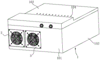
As shown in fig. 1 to 3, the present invention provides a battery box, which includes a box body 1, a partition plate 4, a first exhaust fan 2 and a second exhaust fan 3, and two sets of battery units, wherein the two sets of battery units are a first battery unit 100 and a second battery unit 200, respectively, and the partition plate 4 partitions the interior of the box body 1 into a first chamber and a second chamber. The first exhaust fan 2 and the second exhaust fan 3 are respectively distributed at intervals at the front end of the box body 1, the front end of the box body 1 corresponds to the positions of the first exhaust fan 2 and the second exhaust fan 3, a first air outlet and a second air outlet are respectively formed in the positions, and a plurality of air inlets 104 are formed in the rear end of the box body 1. The first battery unit 100 includes at least two first battery cells, a gap is formed between two adjacent first battery cells to form a first air duct, the second battery unit 200 includes at least two second battery cells, a gap is formed between two adjacent second battery cells to form a second air duct, the first air outlet is communicated with the air inlet 104 through the first air duct, and the second air outlet is communicated with the air inlet 104 through the second air duct.
Because the first air outlet is communicated with the air inlet 104 through the first ventilation channel, cold air outside the box body 1 flows from the air inlet 104 into the first chamber, and the cold air discharges heat in the first battery unit 100 to the outside of the box body 1 through the first ventilation channel under the action of the first exhaust fan 2 so as to cool the first battery unit 100; because the second air outlet is communicated with the air inlet 104 through the second ventilation channel, cold air outside the box body 1 enters the second chamber from the air inlet 104, and the cold air discharges heat in the second battery unit 200 to the outside of the box body 1 through the second ventilation channel under the action of the second exhaust fan 3 so as to cool the second battery unit 200. A ventilation space is reserved between two adjacent electric cores in the same battery unit group through the first ventilation channel and the second ventilation channel, and then heat of each electric core is dissipated. The partition plate 4 is provided to dissipate heat of the first battery cell 100 and the second battery cell 200 by the first suction fan 2 and the second suction fan 3, respectively, and prevent hot air inside the first chamber and hot air inside the second chamber from being accumulated with each other, thereby maintaining the temperature of the first battery cell 100 and the temperature of the second battery cell 200 substantially the same. The battery box is beneficial to reducing the temperature difference between the battery cores and improving the temperature uniformity of the two groups of battery units.
The first air outlet and the second air outlet are located on the same side face of the box body 1. In an embodiment, the first air outlet and the second air outlet are arranged at intervals along the width direction of the box body 1, and in some application occasions, a smaller air exhaust space can be reserved for the battery box in the electric equipment, so that the battery box can be arranged in the electric equipment conveniently. In other embodiments, the first outlet and the second outlet may be distributed at intervals in the length direction of the box body 1. Or, the first air outlet and the second air outlet are distributed at intervals in the height direction of the box body 1.
In this embodiment, the box body 1 has a rectangular structure. The box body 1 comprises an upper cover plate 103, a lower cover plate, a first side plate 102, a second side plate 106, a front end plate 101 and a rear end plate 105, wherein the upper cover plate 103 is located above the lower cover plate, the first side plate 102 is close to the first cavity, and the second side plate 106 is close to the second cavity. The first air outlet and the second air outlet are both arranged on the front end plate 101, and the air inlet 104 is arranged on the rear end plate 105. Wherein, the air outlet distributes along the width direction of case body 1. The upper cover plate 103, the lower cover plate, the first side plate 102, the second side plate 106, the front end plate 101 and the rear end plate 105 may be connected by stamping, die casting, welding, or the like. In other examples, the box body 1 may have other shapes and structures, and the shape and structure of the box body 1 is not particularly limited.
In order to further enhance the ventilation of the battery box, in this embodiment, the upper cover plate 103 is provided with air inlets 104 at positions corresponding to the first chamber and the second chamber, respectively, and the number of the air inlets 104 on the box body 1 is increased through the air inlets 104 on the upper cover plate 103.
Wherein, division board 4 is including the first division board 401, second division board 402 and the third division board that connect gradually, first division board 401 is close to air intake 104 sets up, the third division board is close to the air outlet sets up, the third division board is kept away from the one end and the front end plate 101 of first division board 401 are connected, just the third division board is located first air outlet with between the second air outlet. A gap is formed between the first isolation plate 401 and the first side plate 102 to form a third ventilation channel, the second isolation plate 402 is respectively arranged at intervals with the first battery unit 100 and the second battery unit 200 to respectively form a fourth ventilation channel and a fifth ventilation channel, and a gap is formed between the third isolation plate and the second side plate 106 to form a sixth ventilation channel. The air inlet 104, the third ventilation channel, the fourth ventilation channel, the first ventilation channel and the first air outlet are communicated in sequence, and the air inlet 104, the second ventilation channel, the fifth ventilation channel, the sixth ventilation channel and the second air outlet are communicated in sequence. In practical use, cold air outside the box body 1 enters the box body 1 from the air inlet 104 and then is divided into two parts, and one part of cold air passes through the third air channel and the fourth air channel and then is dispersed in each first air channel of the first battery unit 100, so that heat of the first air channels is discharged to the outside of the box body 1 from the first air outlet; the other part of the cold air enters the second air passage, passes through the fifth air passage and the sixth air passage from the respective second air passages of the second battery unit 200, and is finally discharged to the outside of the box body 1 from the second air outlet.
Preferably, a gap is formed between the first battery unit 100 and the first side plate 102, a first baffle 7 is disposed at a position close to the front end plate 101 in the gap, and the first baffle 7 is spaced from the third through-air duct and the fourth through-air duct, respectively, to form a first buffer portion. Due to the arrangement of the first baffle 7, cold air can be prevented from being directly discharged to the first air outlet from the gap between the first battery unit 100 and the first side plate 102, so that the cold air can be discharged to the first air outlet only after passing through the first air duct, and the heat dissipation efficiency of the first battery unit 100 is improved. The setting of first buffer for the crossing department in third wind channel and fourth wind channel has great space, because division board 4 has the turning department in the middle of first division board 401 in third wind channel and fourth wind channel, utilizes this space to cushion cold air when actual use, guarantees to have enough cold air and enters into the fourth wind channel for the circulation of air speed in third wind channel and the fourth wind channel.
A gap is formed between the second battery cell 200 and the second side plate 106, a second baffle 8 is disposed at a position close to the rear end plate 105 in the gap, and the second baffle 8, the fifth ventilation duct and the sixth ventilation duct are disposed at an interval to form a second buffer portion. Due to the arrangement of the second baffle 8, the possibility that cold air directly flows to the sixth air duct through a gap between the second battery unit 200 and the second side plate 106 after entering from the air inlet 104 can be avoided, sufficient space is reserved at the crossed position of the fifth air duct and the sixth air duct for buffering hot air, and the air circulation speed of the fifth air duct and the sixth air duct is increased.
In this embodiment, the third partition board includes a first board segment 403 and a second board segment 404, the first board segment 403 is located between the second partition board 402 and the second board segment 404, and the second board segment 404 is inclined from the first board segment 403 to the direction of the first side board 102. A guide plate 12 is arranged between the first battery unit 100 and the front end plate 101, one end of the guide plate 12 is connected with the first baffle 7, the other end of the guide plate 12 is connected with the front end plate 101, the guide plate 12 is inclined towards the second side plate 106 by the first baffle 7, and the first plate section 403 and the guide plate 12 form a guide assembly. Since the second plate section 404 is inclined from the first plate section 403 toward the first side plate 102 and the flow guide plate 12 is inclined from the first baffle 7 toward the second side plate 106, the gap between the first battery unit 100 and the front end plate 101 gradually decreases from the direction close to the first battery unit 100 toward the direction close to the front end, which is beneficial for the first air outlet to discharge the air inside the first chamber to the outside of the box body 1.
In order to connect the third isolation plate to the front end plate 101 conveniently, in this embodiment, a connection section plate 405 is disposed at an end of the second plate section 404 away from the first plate section 403, and one end of the connection section plate 405 is connected to the second plate section 404 and the other end is connected to the front end plate 101. Preferably, the connecting segment plate 405 is perpendicular to the front end plate 101.
In this embodiment, in order to facilitate the connection of the external electric equipment to the battery box, the first battery unit 100 is provided with a connection terminal 9, and the second battery unit 200 is connected to the connection terminal 9 through a connection wire 15. Wherein the connection terminal 9 extends to the outside of the tank body 1 through the front end plate 101.
Specifically, the first baffle 7 includes a first baffle body 701 and a second baffle body 702, one end of the first baffle body 701 is connected to the front end plate 101, and the other end is connected to the second baffle body 702. One end of the second baffle body 702, which is far away from the first baffle body 701, is connected to the first side plate 102, and one end of the guide plate 12, which is far away from the front end plate 101, is connected to the first baffle body 701. The second baffle 8 includes a third baffle body 801 and a fourth baffle body 802, one end of the third baffle body 801 is connected to the rear end plate 105, and the other end is connected to the fourth baffle body 802.
In this embodiment, the first battery unit 100 includes at least two first battery modules 5 disposed at intervals, the at least two first battery modules 5 are arranged at intervals along the length direction of the box body 1, and each of the two first battery modules 5 includes at least two first battery cells. The first battery cells in the same first battery module 5 are arranged at intervals along the width direction of the box body 1, and a first ventilation channel is formed in a gap between the two first battery cells in the same first battery module 5. Preferably, the first air ducts in different first battery modules 5 correspond to each other one by one, so that the cold air directly passes through the second air duct of another first battery module 5 from the first air duct of one of the first battery modules 5.
The second battery unit 200 includes at least two second battery modules 6 arranged at intervals, the at least two second battery modules 6 are arranged at intervals along the length direction of the box body 1, and the two second battery modules 6 each include at least two second battery cells. The second battery cells in the same second battery module 6 are arranged at intervals along the width direction of the box body 1, and a second ventilation channel is formed in a gap between the two second battery cells in the same second battery module 6. Preferably, the second ventilation channels in different second battery modules 6 correspond to each other one by one, so that the cold air directly passes through the second ventilation channel of one second battery module 6 from the second ventilation channel of another second battery module 6.
In one embodiment, the first battery unit 100 and the second battery unit 200 are connected by a connection plate 11, and the first battery unit 100 and the second battery unit 200 can be integrally connected by the connection plate 11. In order to reinforce the connection strength between the first battery cell 100 and the second battery cell 200, the connection plate 11 is connected to the second separator 402, and the connection plate 11 is supported by the second separator 402. Specifically, the first battery module 5 and the second battery module 6 disposed adjacent to each other are connected by the connection plate 11, and the first battery cell 100 and the second battery cell 200 are connected.
Furthermore, a through hole is opened in the second isolation plate 402, the connection plate 11 passes through the through hole from the first battery unit 100 to be connected with the second battery unit 200, and the second isolation plate 402 abuts against the hole wall of the through hole.
Specifically, two adjacent first battery modules 5 and two second battery modules 6 are connected through a connecting plate 11, so that the connection between the two battery modules is realized.
In this embodiment, two first battery modules 5 and two second battery modules 6 are provided, and in another embodiment, the number of the first battery modules 5 or the second battery modules 6 may be set to be one, three, four, or five.
Each first battery module 5 all includes first fixed plate 501, first fixed plate 501 is located the top of first electric core, just first fixed plate 501 along 1 width direction of case body extends, the both ends of first fixed plate 501 are established respectively and are connected with two first fixed frames 502, and is same each first electric core in first battery module 5 all is located between two first fixed frames 502.
Each second battery module 6 all includes second fixed plate 601, second fixed plate 601 is located the top of second electricity core, just second fixed plate 601 along the 1 width direction of case body extends, the fixed frame 602 of two second is established respectively at the both ends of second fixed plate 601, and is same each second electricity core in second battery module 6 all is located between the fixed frame 602 of two second.
Specifically, each connecting plate 11 is connected to the first fixing plate 501 or the second fixing plate 601, and the first fixing plate 501 and the second fixing plate 601 are insulating plates.
Further, a spacing bracket (not shown) is arranged between two adjacent first battery cells in the same first battery module 5 and between two adjacent second battery cells in the same second battery module 6. The arrangement of the spacing support is used for reserving a gap between two adjacent battery cores on one hand, and is used for supporting the battery cores by using the spacing support on the other hand. In another embodiment, gaskets may be disposed between two adjacent first battery cells in the same first battery module 5 and between two adjacent second battery cells in the same second battery module 6, and gaps may be formed between the two adjacent battery cells by the gaskets.
The periphery of the first battery module 5 is provided with a first binding band 503, and all the first battery cells in one first battery module 5 are fixed to the first fixing frame 502 by the first binding band 503. In this embodiment, two first binding bands 503 are disposed in the same first battery module 5, and the two first binding bands 503 are distributed at intervals along the first battery cell height direction.
The periphery of the second battery module 6 is provided with a second binding band 603, and all the second cells in one second battery module 6 and the second fixing frame 602 are fixed by the second binding band 603. In this embodiment, two second binding bands 603 are disposed in the same second battery module 6, and the two second binding bands 603 are distributed at intervals along the second cell height direction.
In this embodiment, the battery box further includes two fixing strips 14, 14 positions of the fixing strips are disposed between the lower cover plate and the battery unit, the two fixing strips 14 extend along the length direction of the box body 1, and each of the first battery module 5 and each of the second battery module 6 is connected to the fixing strip 14. Specifically, first connecting hole has all been seted up to the fixed frame of first 502 and the fixed frame of second 602, the fixed strip 14 corresponds the second connecting hole has been seted up to first connecting frame, and connecting screw 13 screws up respectively in first connecting hole and the second connecting hole, realize first battery module 5 and second battery module 6 and respectively with the connection of fixed strip 14.
In order to further strengthen the structure inside the battery box, the partition plate 4, the first baffle plate 7 and the second baffle plate 8 are connected with the fixing strip 14.
In one embodiment, the first baffle 7 is connected to the first battery cell 100 through a first auxiliary plate. Specifically, a third connecting hole is formed in one end of the first auxiliary plate, the connecting screw 13 is screwed in the first connecting hole and the third connecting hole at the same time, so that the first auxiliary plate is connected with the first fixed frame 502, and one end of the first auxiliary plate, which is far away from the first fixed frame 502, is connected with the first baffle body 701.
In another embodiment, the second barrier 8 is connected to the second battery cell 200 via a second auxiliary plate. Specifically, a fourth connecting hole is formed in one end of the second auxiliary plate, the connecting screw 13 is screwed into the first connecting hole and the fourth connecting hole at the same time, so that the second auxiliary plate is connected with the second fixed frame 602, and one end of the second auxiliary plate, which is far away from the second fixed frame 602, is connected with the third baffle body 801.
A fourth connecting hole is formed in the first fixing plate 501, and the connecting screw 13 is screwed into the first connecting hole and the fourth connecting hole, so that the first fixing plate 501 and the first fixing frame 502 can be detachably connected.
In this embodiment, a BMU10 is disposed at one end of the first fixing plate 501 close to the upper cover plate 103, and an avoiding groove is convexly disposed towards the outside of the box body 1 at a position of the upper cover plate 103 corresponding to the BMU 10.
In the description herein, it is to be understood that the terms "upper," "lower," "left," "right," and the like are based on the orientation or positional relationship shown in the drawings for convenience in description and simplicity of operation, and do not indicate or imply that the referenced device or element must have a particular orientation, be constructed and operated in a particular orientation, and are not to be considered limiting of the present invention. Furthermore, the terms "first" and "second" are used only for descriptive purposes and are not intended to have a special meaning.
In the description herein, references to the description of "an embodiment," "an example" or the like are intended to mean that a particular feature, structure, material, or characteristic described in connection with the embodiment or example is included in at least one embodiment or example of the invention. In this specification, the schematic representations of the terms used above do not necessarily refer to the same embodiment or example.
Furthermore, it should be understood that although the present description refers to embodiments, not every embodiment may contain only a single embodiment, and such description is for clarity only, and those skilled in the art should integrate the description, and the embodiments may be appropriately combined to form other embodiments as will be appreciated by those skilled in the art.
The technical principle of the present invention is described above in connection with specific embodiments. The description is made for the purpose of illustrating the principles of the invention and should not be construed in any way as limiting the scope of the invention. Based on the explanations herein, those skilled in the art will be able to conceive of other embodiments of the present invention without inventive effort, which would fall within the scope of the present invention.