CN110251225B - A method for establishing a three-dimensional intersecting damage grid and a lesion damage system - Google Patents
A method for establishing a three-dimensional intersecting damage grid and a lesion damage system Download PDFInfo
- Publication number
- CN110251225B CN110251225B CN201910380061.8A CN201910380061A CN110251225B CN 110251225 B CN110251225 B CN 110251225B CN 201910380061 A CN201910380061 A CN 201910380061A CN 110251225 B CN110251225 B CN 110251225B
- Authority
- CN
- China
- Prior art keywords
- damage
- grid
- distance
- electrodes
- dimensional
- Prior art date
- Legal status (The legal status is an assumption and is not a legal conclusion. Google has not performed a legal analysis and makes no representation as to the accuracy of the status listed.)
- Active
Links
Images

Classifications
-
- A—HUMAN NECESSITIES
- A61—MEDICAL OR VETERINARY SCIENCE; HYGIENE
- A61B—DIAGNOSIS; SURGERY; IDENTIFICATION
- A61B18/00—Surgical instruments, devices or methods for transferring non-mechanical forms of energy to or from the body
- A61B18/04—Surgical instruments, devices or methods for transferring non-mechanical forms of energy to or from the body by heating
- A61B18/08—Surgical instruments, devices or methods for transferring non-mechanical forms of energy to or from the body by heating by means of electrically-heated probes
- A61B18/082—Probes or electrodes therefor
-
- G—PHYSICS
- G06—COMPUTING OR CALCULATING; COUNTING
- G06F—ELECTRIC DIGITAL DATA PROCESSING
- G06F30/00—Computer-aided design [CAD]
- G06F30/20—Design optimisation, verification or simulation
-
- G—PHYSICS
- G06—COMPUTING OR CALCULATING; COUNTING
- G06T—IMAGE DATA PROCESSING OR GENERATION, IN GENERAL
- G06T17/00—Three dimensional [3D] modelling, e.g. data description of 3D objects
- G06T17/20—Finite element generation, e.g. wire-frame surface description, tesselation
-
- A—HUMAN NECESSITIES
- A61—MEDICAL OR VETERINARY SCIENCE; HYGIENE
- A61B—DIAGNOSIS; SURGERY; IDENTIFICATION
- A61B18/00—Surgical instruments, devices or methods for transferring non-mechanical forms of energy to or from the body
- A61B2018/00315—Surgical instruments, devices or methods for transferring non-mechanical forms of energy to or from the body for treatment of particular body parts
- A61B2018/00321—Head or parts thereof
Landscapes
- Engineering & Computer Science (AREA)
- Physics & Mathematics (AREA)
- Health & Medical Sciences (AREA)
- Life Sciences & Earth Sciences (AREA)
- Surgery (AREA)
- Theoretical Computer Science (AREA)
- General Physics & Mathematics (AREA)
- Heart & Thoracic Surgery (AREA)
- Plasma & Fusion (AREA)
- Geometry (AREA)
- Nuclear Medicine, Radiotherapy & Molecular Imaging (AREA)
- Otolaryngology (AREA)
- Veterinary Medicine (AREA)
- Public Health (AREA)
- Biomedical Technology (AREA)
- General Health & Medical Sciences (AREA)
- Medical Informatics (AREA)
- Molecular Biology (AREA)
- Animal Behavior & Ethology (AREA)
- General Engineering & Computer Science (AREA)
- Computer Hardware Design (AREA)
- Evolutionary Computation (AREA)
- Computer Graphics (AREA)
- Software Systems (AREA)
- Electrotherapy Devices (AREA)
Abstract
本发明实施例涉及一种立体交叉毁损网格的建立方法及病灶毁损系统,所述建立方法包括:确定立体交叉毁损网格的节点为电极的触点;确定立体交叉毁损网格的边,所述边对应的两个电极的触点间距小于或等于毁损距离;基于节点和边,建立立体交叉毁损网格。本发明实施例中,建立的立体交叉毁损网格中,每条边对应的两个电极的触电之间可形成偶极电场,进而形成毁损灶;并且由于边对应的两个电极的触点间距小于或等于毁损距离,使得毁损灶为连续的毁损灶,进而使得建立的立体交叉毁损网格增大了毁损灶的毁损范围,能够对立体病灶实现完全覆盖。

The embodiment of the present invention relates to a method for establishing a three-dimensional intersection damaged grid and a lesion damage system. The establishment method includes: determining that a node of the three-dimensional intersecting damaged grid is a contact point of an electrode; The contact distance of the two electrodes corresponding to the edge is less than or equal to the damage distance; based on the nodes and edges, a three-dimensional intersection damage grid is established. In the embodiment of the present invention, in the established three-dimensional cross damage grid, a dipole electric field can be formed between the electric shocks of the two electrodes corresponding to each edge, thereby forming a damage focus; and due to the contact distance between the two electrodes corresponding to the edge The damage distance is less than or equal to the damage distance, so that the damage focus is a continuous damage focus, so that the established three-dimensional cross damage grid increases the damage range of the damage focus and can completely cover the three-dimensional focus.
Description
技术领域technical field
本发明实施例涉及病灶毁损技术领域,具体涉及一种立体交叉毁损网格的建立方法、病灶毁损系统及非暂态计算机可读存储介质。Embodiments of the present invention relate to the technical field of lesion damage, and in particular, to a method for establishing a three-dimensional intersection damage grid, a lesion damage system, and a non-transitory computer-readable storage medium.
背景技术Background technique
传统的立体定向射频热凝由于毁损范围较小而广受诟病,目前并未成为国际公认的一线治疗。目前,对于局灶性、远离功能区的致痫灶,最好的办法是清除它。其中一种清除的方法,是立体定向射频热凝毁损(Radio Frequency thermocoagulation,RF-TC),该方法是通过位于颅内的双极电场产热,通常温度达到75-80℃,来灭活颅内的病灶组织。该方法问世于1947年,已长时间用于癫痫患者。然而,传统的RF-TC方法不能同时记录颅内的电活动。Traditional stereotactic radiofrequency thermocoagulation has been widely criticized due to its small damage range, and it has not become an internationally recognized first-line treatment. Currently, for focal, distant epileptogenic foci, the best approach is to remove it. One such removal method is stereotactic radiofrequency thermocoagulation (RF-TC), which inactivates the skull by generating heat through a bipolar electric field located in the brain, usually at a temperature of 75-80°C. within the lesion tissue. This method was introduced in 1947 and has been used for a long time in epilepsy patients. However, conventional RF-TC methods cannot simultaneously record intracranial electrical activity.
立体定向脑电图(stereoelectroencephalography,SEEG)颅内电极可用于癫痫患者颅内脑电活动的记录,通过该电极进行射频热凝毁损的报道见于2004年,该方法也用于致痫灶的毁损治疗,该技术即可记录异常脑电,又可不用更换电极位置直接在颅内进行毁损治疗。然而,无论是传统的RF-TC,还是SEEG引导下的RF-TC,都由于毁损范围小,目前在国际上,并未作为致痫灶清除的一线治疗来使用。Stereoelectroencephalography (SEEG) intracranial electrodes can be used to record intracranial EEG activity in patients with epilepsy. The report of radiofrequency thermal coagulation damage by this electrode was found in 2004, and this method is also used for the damage treatment of epileptogenic foci , the technology can record abnormal EEG, and can directly perform damage treatment in the brain without changing the electrode position. However, both traditional RF-TC and SEEG-guided RF-TC are not currently used internationally as first-line treatment for epileptogenic foci removal due to the small damage range.
为了研究如何扩大毁损范围,近年来癫痫的欧洲中心和北美中心相继通过蛋清实验发现了相隔一定距离的两个触点所构成的偶极电场可以显著扩大毁损范围。然而,目前在全世界范围内,RF-TC 仍然停留在较低的空间维度(一维),所产生的毁损范围较为零星,不足以完整覆盖自然形成的致痫灶。而且,蛋清并不是均质的,当中包含有很多密度不同的层次,并不足以充分推理出RF-TC的详细参数。In order to study how to expand the damage range, in recent years, the European Center of Epilepsy and the North American Center have successively discovered through egg white experiments that the dipole electric field formed by two contacts separated by a certain distance can significantly expand the damage range. However, worldwide, RF-TC still remains in a lower spatial dimension (one-dimensional), and the resulting lesions are sporadic and insufficient to completely cover naturally occurring epileptogenic foci. Moreover, egg whites are not homogeneous and contain many layers with different densities, which are not sufficient to fully reason about the detailed parameters of RF-TC.
上述对问题的发现过程的描述,仅用于辅助理解本发明的技术方案,并不代表承认上述内容是现有技术。The above description of the discovery process of the problem is only used to assist the understanding of the technical solution of the present invention, and does not mean that the above content is the prior art.
发明内容SUMMARY OF THE INVENTION
为了解决现有技术存在的至少一个问题,本发明的至少一个实施例提供了一种立体交叉毁损网格的建立方法、病灶毁损系统及非暂态计算机可读存储介质。In order to solve at least one problem existing in the prior art, at least one embodiment of the present invention provides a method for establishing a three-dimensional intersection damage grid, a lesion damage system, and a non-transitory computer-readable storage medium.
为此目的,第一方面,本发明实施例提出一种立体交叉毁损网格的建立方法,所述方法包括:To this end, in a first aspect, an embodiment of the present invention provides a method for establishing a three-dimensional intersection damaged grid, the method comprising:
确定立体交叉毁损网格的节点为电极的触点;Determine the nodes of the three-dimensional intersection damaged grid as the contacts of the electrodes;
确定立体交叉毁损网格的边,所述边对应的两个电极的触点间距小于或等于毁损距离;Determine the edge of the three-dimensional intersection damage grid, and the contact distance of the two electrodes corresponding to the edge is less than or equal to the damage distance;
基于所述节点和所述边,建立立体交叉毁损网格。Based on the nodes and the edges, a three-dimensional intersection damage mesh is built.
在一些实施例中,所述确定立体交叉毁损网格的边,包括:In some embodiments, the determining the edges of the intersection damage mesh includes:
对于同一电极,若该同一电极与多个电极的触点 间距均小于或等于毁损距离,则确定该同一电极对应多条边,且所述多条边的条数与所述多个电极的个数相同。For the same electrode, if the contact distance between the same electrode and multiple electrodes is less than or equal to the damage distance, then it is determined that the same electrode corresponds to multiple sides, and the number of the multiple sides is the same as the number of the multiple electrodes. same number.
在一些实施例中,所述建立立体交叉毁损网格,包括:设置任意两个电极平行或成角度。In some embodiments, the establishing the three-dimensional cross-damaged grid includes: arranging any two electrodes to be parallel or angled.
在一些实施例中,所述方法还包括:设置立体交叉毁损网格的毁损参数值。In some embodiments, the method further comprises: setting a damage parameter value of the three-dimensional intersection damage grid.
在一些实施例中,所述立体交叉毁损网格的毁损参数值,包括:电极功率和毁损时长。In some embodiments, the damage parameter values of the three-dimensional intersection damage grid include: electrode power and damage duration.
在一些实施例中,所述电极功率为3瓦,所述毁损时长设置为 60秒至80秒之间的任一值。In some embodiments, the electrode power is 3 watts, and the damage duration is set to any value between 60 seconds and 80 seconds.
在一些实施例中,所述毁损距离为7毫米。In some embodiments, the damage distance is 7 millimeters.
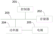
第二方面,本发明实施例还提出一种病灶毁损系统,包括:控制器、存储器、功率源和多个电极;In a second aspect, an embodiment of the present invention further provides a lesion destruction system, including: a controller, a memory, a power source, and a plurality of electrodes;
所述控制器分别连接所述存储器和所述功率源;the controller is connected to the memory and the power source, respectively;
所述功率源连接所述多个电极;the power source is connected to the plurality of electrodes;
所述控制器通过调用所述存储器存储的程序,用于执行如第一方面所述方法的步骤。The controller is configured to execute the steps of the method according to the first aspect by calling the program stored in the memory.
第三方面,本发明实施例还提出一种非暂态计算机可读存储介质,所述非暂态计算机可读存储介质存储程序,所述程序使计算机执行如第一方面所述方法的步骤。In a third aspect, an embodiment of the present invention further provides a non-transitory computer-readable storage medium, where the non-transitory computer-readable storage medium stores a program, and the program causes a computer to execute the steps of the method according to the first aspect.
可见,本发明实施例的至少一个实施例中,建立的立体交叉毁损网格中,每条边对应的两个电极的触点 之间可形成偶极电场,进而形成毁损灶;并且由于边对应的两个电极的触点间距小于或等于毁损距离,使得毁损灶为连续的毁损灶,进而使得建立的立体交叉毁损网格增大了毁损灶的毁损范围,能够对立体病灶实现完全覆盖。It can be seen that in at least one embodiment of the present invention, in the established three-dimensional cross-damaged grid, a dipole electric field can be formed between the contacts of the two electrodes corresponding to each edge, thereby forming a damage focus; and because the edges correspond to The contact distance between the two electrodes is less than or equal to the damage distance, so that the damage focus is a continuous damage focus, so that the established three-dimensional cross damage grid increases the damage range of the damage focus and can completely cover the three-dimensional focus.
附图说明Description of drawings
为了更清楚地说明本发明实施例的技术方案,下面将对实施例或现有技术描述中所需要使用的附图作简单地介绍,显而易见地,下面描述中的附图仅仅是本发明的一些实施例,对于本领域普通技术人员来讲,还可以根据这些附图获得其他的附图。In order to illustrate the technical solutions of the embodiments of the present invention more clearly, the following briefly introduces the accompanying drawings that need to be used in the description of the embodiments or the prior art. Obviously, the drawings in the following description are only some of the present invention. Embodiments For those of ordinary skill in the art, other drawings can also be obtained according to these drawings.
图1为本发明实施例提供的一种立体交叉毁损网格的建立方法流程图;FIG. 1 is a flowchart of a method for establishing a three-dimensional intersection damage grid according to an embodiment of the present invention;
图2为本发明实施例提供的一种病灶毁损系统结构框图。FIG. 2 is a structural block diagram of a system for lesion damage provided by an embodiment of the present invention.
具体实施方式Detailed ways
为了能够更清楚地理解本发明的上述目的、特征和优点,下面结合附图和实施例对本发明作进一步的详细说明。可以理解的是,所描述的实施例是本发明的一部分实施例,而不是全部的实施例。此处所描述的具体实施例仅仅用于解释本发明,而非对本发明的限定。基于所描述的本发明的实施例,本领域普通技术人员所获得的所有其他实施例,都属于本发明保护的范围。In order to understand the above objects, features and advantages of the present invention more clearly, the present invention will be further described in detail below with reference to the accompanying drawings and embodiments. It is to be understood that the described embodiments are some, but not all, embodiments of the present invention. The specific embodiments described herein are only used to explain the present invention, but not to limit the present invention. Based on the described embodiments of the present invention, all other embodiments obtained by those of ordinary skill in the art fall within the protection scope of the present invention.
为了在三维空间中,建立起足以覆盖立体病灶的毁损区域,本申请发明人发现在计算机辅助设计(Computer Aided Design,CAD) 领域,有一种描绘三维空间中物体的方法,是将物体的三维模型网格化(Meshlization)。由此,本申请发明人提出:In order to establish a damaged area sufficient to cover a three-dimensional lesion in a three-dimensional space, the inventor of the present application found that in the field of Computer Aided Design (CAD), there is a method for describing an object in a three-dimensional space, which is to use a three-dimensional model of the object. Meshlization. Therefore, the inventor of the present application proposes:
三维空间中的RF-TC不能仅依托于单一一对电极形成的偶极电场,而应依托于多对电极形成的偶极电场构成的网格(Mesh Grid)。偶极电场由相隔一段距离的排列不同(平行或成角度)的电极上的触点所形成,触点就相当于网格的节点或顶点,触点间的偶极电场相当于网格的边。The RF-TC in three-dimensional space cannot rely only on the dipole electric field formed by a single pair of electrodes, but should rely on the Mesh Grid formed by the dipole electric field formed by multiple pairs of electrodes. The dipole electric field is formed by contacts on electrodes that are arranged differently (parallel or angled) at a distance. The contacts are equivalent to the nodes or vertices of the grid, and the dipole electric field between the contacts is equivalent to the edges of the grid. .
本申请发明人对以上描述中提及的节点和边的性质进行了大量定量化实验的验证,将以上描述命名为立体交叉毁损的理论体系,以上描述中提及的网格称为立体交叉毁损网格。The inventor of the present application has carried out a large number of quantitative experiments to verify the properties of the nodes and edges mentioned in the above description, and named the above description as the theoretical system of three-dimensional intersection damage, and the grid mentioned in the above description is called three-dimensional intersection damage. grid.
实施例中公开的立体交叉毁损网格的建立方法,既可用于生物体中病灶的消除/损毁,也可用于非诊断或治疗目的的体外实验及科学研究等方面。本发明所提供的立体交叉毁损网格的建立方法,不局限于临床应用。The method for establishing a three-dimensional cross-destroyed grid disclosed in the embodiment can be used not only for eliminating/destroying lesions in an organism, but also for in vitro experiments and scientific research for non-diagnostic or therapeutic purposes. The method for establishing the three-dimensional intersection damaged grid provided by the present invention is not limited to clinical application.
图1为本发明实施例提供的一种立体交叉毁损网格的建立方法流程图,该方法可包括以下步骤101至103:1 is a flowchart of a method for establishing a three-dimensional intersection damage grid provided by an embodiment of the present invention, and the method may include the
101、确定立体交叉毁损网格的节点为电极的触点。101. Determine the nodes of the three-dimensional intersection damaged grid as the contacts of the electrodes.
102、确定立体交叉毁损网格的边,所述边对应的两个电极的触点间距小于或等于毁损距离。102. Determine the edge of the three-dimensional intersection damage grid, where the contact distance between the two electrodes corresponding to the edge is less than or equal to the damage distance.
103、基于节点和边,建立立体交叉毁损网格。103. Based on nodes and edges, establish a three-dimensional intersection damage grid.
本实施例中,立体交叉毁损网格为三维网格(3D mesh)。可以理解,立体交叉毁损网格的节点用于设置电极,间接表明节点用于设置电极的触点,也即建立立体交叉毁损网格的过程中,节点可以为虚拟节点,在建立立体交叉毁损网格后,再将电极设置在节点所在位置。In this embodiment, the three-dimensional intersection damage mesh is a three-dimensional mesh (3D mesh). It can be understood that the nodes of the three-dimensional cross-damaged grid are used to set electrodes, which indirectly indicates that the nodes are used to set the contacts of the electrodes, that is, in the process of establishing the three-dimensional cross-damaged grid, the nodes can be virtual nodes. After the grid, set the electrode at the position of the node.
在一些实施例中,建立立体交叉毁损网格包括:设置任意两个电极平行或成角度。通过两个平行或成角度的电极的触点,可以形成偶极电场,并进而形成毁损灶。In some embodiments, establishing the three-dimensional cross-destruction grid includes arranging any two electrodes to be parallel or angled. Through the contact of two parallel or angled electrodes, a dipole electric field can be formed, and thus a lesion foci.
本申请发明人发现,两个电极的触点间距影响毁损灶的连续性。具体地,将毁损灶连续和毁损灶分离的临界距离称为毁损距离。The inventor of the present application found that the contact distance between the two electrodes affects the continuity of the lesion. Specifically, the critical distance between the continuation of the lesion and the separation of the lesion is called the damage distance.
若两个电极的触点间距大于毁损距离,则两个电极的触点间不能形成连续的毁损灶,并且毁损体积明显下降。If the contact distance of the two electrodes is greater than the damage distance, a continuous damage focus cannot be formed between the contacts of the two electrodes, and the damage volume is significantly reduced.
若两个电极的触点间距小于或等于毁损距离,则两个电极的触点间形成连续的毁损灶,并且本申请发明人发现,在毁损距离内,触点间距越大,毁损范围越大,虽然毁损的强度降低,但毁损灶的温度仍然足够引起组织的不可逆灭活。If the contact distance of the two electrodes is less than or equal to the damage distance, a continuous damage focus is formed between the contacts of the two electrodes, and the inventors of the present application found that within the damage distance, the larger the contact distance, the greater the damage range. , although the intensity of the lesions is reduced, the temperature of the lesions is still sufficient to cause irreversible tissue inactivation.
在一些实施例中,确定立体交叉毁损网格的边,包括:In some embodiments, determining the edges of the intersection damage mesh includes:
对于同一电极,若该同一电极与多个电极的触点 间距均小于或等于毁损距离,则确定该同一电极对应多条边,且所述多条边的条数与所述多个电极的个数相同。For the same electrode, if the contact distance between the same electrode and multiple electrodes is less than or equal to the damage distance, then it is determined that the same electrode corresponds to multiple sides, and the number of the multiple sides is the same as the number of the multiple electrodes. same number.
本申请发明人发现,热凝毁损中,通过同一个电极的触点可与周围毁损距离内不同电极的触点多次形成连续的毁损灶,也即热凝毁损中,触点具有可多重连接属性。The inventors of the present application found that, in the thermal coagulation damage, the contact of the same electrode can form a continuous damage zone multiple times with the contacts of different electrodes within the surrounding damage distance. Attributes.
在一些实施例中,立体交叉毁损网格的建立方法还可包括步骤:设置立体交叉毁损网格的毁损参数值。立体交叉毁损网格的毁损参数值包括但不限于:电极功率和毁损时长。设置毁损参数值可在建立立体交叉毁损网格后执行,也可在流程开始前执行,也可在建立过程中执行。In some embodiments, the method for establishing a three-dimensional intersection damage grid may further include the step of: setting a damage parameter value of the three-dimensional intersection damage grid. The damage parameter values of the three-dimensional intersection damage grid include but are not limited to: electrode power and damage duration. Setting the damage parameter values can be performed after the stereocross damage mesh is created, before the process starts, or during the creation process.
本申请发明人发现,通过两个平行或成角度的电极的触点,用3 瓦的电极功率,150秒的毁损时长,触点间距在7毫米内(也即毁损距离为7毫米,且触点间距≤毁损距离),可以形成偶极电场,并进而形成连续的毁损灶。毁损灶的温度为65℃至82℃之间。The inventors of the present application have found that, through the contacts of two parallel or angled electrodes, with an electrode power of 3 watts and a damage time of 150 seconds, the contact spacing is within 7 mm (that is, the damage distance is 7 mm, and the contact distance is 7 mm and the contact distance is 7 mm). point spacing ≤ damage distance), a dipole electric field can be formed, and then a continuous damage focus can be formed. The temperature of the lesions was between 65°C and 82°C.
本申请发明人发现,触点间距在7毫米内,触点间距越大,毁损范围越大,但毁损的强度降低。但即使毁损的强度降低,所产生的温度仍足够引起组织的不可逆灭活。而当触点间距大于7毫米,例如9毫米,则不能形成连续的毁损灶,而且,毁损体积明显下降。The inventors of the present application found that when the contact distance is within 7 mm, the larger the contact distance is, the larger the damage range is, but the damage intensity is reduced. But even if the damage is reduced in intensity, the resulting temperature is still sufficient to cause irreversible inactivation of the tissue. However, when the contact distance is greater than 7 mm, for example, 9 mm, continuous damage cannot be formed, and the damage volume is significantly reduced.
本申请发明人还发现,当触点距离小于7毫米时,毁损灶的毁损直径的增长存在平台期,该平台期通常在毁损开始后60秒内出现,出现平台期后750秒的长时观察,发现毁损直径仅增大了1.3至1.4 倍。由此,本申请发明人提出,立体交叉毁损时,当触点距离小于7毫米时,应尽可能的分散,以达到最大的毁损范围,而且为了提升毁损的效率,每一对触点间的毁损时长设置为60秒至80秒之间的任一值,也即,60秒≤毁损时长≤80秒。The inventors of the present application also found that when the contact distance is less than 7 mm, there is a plateau in the growth of the lesion diameter of the lesion. The plateau usually occurs within 60 seconds after the damage starts, and a long-term observation of 750 seconds after the plateau occurs. , it was found that the lesion diameter increased only by a factor of 1.3 to 1.4. Therefore, the inventor of the present application proposes that when the three-dimensional intersection is damaged, when the contact distance is less than 7 mm, it should be dispersed as much as possible to achieve the largest damage range. The damage duration is set to any value between 60 seconds and 80 seconds, that is, 60 seconds≤damage duration≤80 seconds.
可见,以上实施例建立的立体交叉毁损网格中,每条边对应的两个电极的触点 之间可形成偶极电场,进而形成毁损灶;并且由于边对应的两个电极的触点间距小于或等于毁损距离,使得毁损灶为连续的毁损灶,进而使得建立的立体交叉毁损网格增大了毁损灶的毁损范围,能够对立体病灶实现完全覆盖。It can be seen that in the three-dimensional intersecting damage grid established in the above embodiment, a dipole electric field can be formed between the contacts of the two electrodes corresponding to each edge, thereby forming a damage focus; and the distance between the contacts of the two electrodes corresponding to the edge The damage distance is less than or equal to the damage distance, so that the damage focus is a continuous damage focus, so that the established three-dimensional cross damage grid increases the damage range of the damage focus and can completely cover the three-dimensional focus.
另外,以上实施例建立的立体交叉毁损网格,改变了目前局限于低空间维度而不能有效覆盖立体病灶的传统毁损体系;使毁损过程充分覆盖三维的毁损空间,显著扩大了立体病灶的毁损范围。In addition, the three-dimensional intersecting damage grid established in the above embodiment changes the current traditional damage system that is limited to low spatial dimensions and cannot effectively cover three-dimensional lesions; the damage process fully covers the three-dimensional damage space, which significantly expands the damage range of three-dimensional lesions. .
图2是本发明实施例提供的一种病灶毁损系统的结构示意图。FIG. 2 is a schematic structural diagram of a lesion destruction system provided by an embodiment of the present invention.
图2所示的病灶毁损系统包括:控制器201、存储器202、功率源204和多个电极205,为简化图示,图2中仅示出一个电极205,电极205的个数可根据实际需要进行设置。所述控制器201分别连接所述存储器202和所述功率源204;所述功率源204连接所述多个电极205。The lesion destruction system shown in FIG. 2 includes: a
控制器201可控制功率源204向多个电极205提供3瓦的电极功率,电极功率时长控制为150秒,实现150秒的毁损时长,电极的触点间距在7毫米内(也即毁损距离为7毫米,且触点间距≤毁损距离),可以形成偶极电场,并进而形成连续的毁损灶。毁损灶的温度为65℃至82℃之间。The
在一些实施例中,病灶毁损系统可包括多个控制器201,多个存储器202,个数可根据实际需要进行设置。病灶毁损系统中的各个组件可通过总线系统203耦合在一起。可理解,总线系统203用于实现这些组件之间的连接通信。总线系统203除包括数据总线之外,还包括电源总线、控制总线和状态信号总线。但为了清楚说明起见,在图2中将各种总线都标为总线系统203。In some embodiments, the lesion destruction system may include
可以理解,本实施例中的存储器202可以是易失性存储器或非易失性存储器,或可包括易失性和非易失性存储器两者。其中,非易失性存储器可以是只读存储器(Read-OnlyMemory,ROM)、可编程只读存储器(Programmable ROM,PROM)、可擦除可编程只读存储器(Erasable PROM,EPROM)、电可擦除可编程只读存储器 (Electrically EPROM,EEPROM)或闪存。易失性存储器可以是随机存取存储器(Random Access Memory,RAM),其用作外部高速缓存。通过示例性但不是限制性说明,许多形式的RAM可用,例如静态随机存取存储器(Static RAM,SRAM)、动态随机存取存储器(Dynamic RAM,DRAM)、同步动态随机存取存储器(Synchronous DRAM,SDRAM)、双倍数据速率同步动态随机存取存储器 (DoubleDataRateSDRAM,DDRSDRAM)、增强型同步动态随机存取存储器(Enhanced SDRAM,ESDRAM)、同步连接动态随机存取存储器(Synchlink DRAM,SLDRAM)和直接内存总线随机存取存储器(DirectRambus RAM,DRRAM)。本文描述的存储器202旨在包括但不限于这些和任意其它适合类型的存储器。It is understood that the
在本发明实施例中,控制器201通过调用存储器202存储的程序,用于执行方法各实施例的步骤,例如可包括以下步骤一至步骤三:In this embodiment of the present invention, the
步骤一、确定立体交叉毁损网格的节点为电极的触点。Step 1: Determine the nodes of the three-dimensional intersection damaged grid as the contacts of the electrodes.
步骤二、确定立体交叉毁损网格的边,所述边对应的两个电极的触点间距小于或等于毁损距离。Step 2: Determine the edge of the three-dimensional intersection damage grid, and the contact distance between the two electrodes corresponding to the edge is less than or equal to the damage distance.
步骤三、基于所述节点和所述边,建立立体交叉毁损网格。Step 3: Based on the nodes and the edges, establish a three-dimensional intersection damage grid.
上述本发明实施例揭示的方法可以应用于控制器201中,或者由控制器201实现。控制器201可能是一种集成电路芯片,具有信号的处理能力。在实现过程中,上述方法的各步骤可以通过控制器 201中的硬件的集成逻辑电路或者软件形式的指令完成。上述的控制器201可以是通用处理器、数字信号处理器(Digital Signal Processor, DSP)、专用集成电路(Application Specific Integrated Circuit,ASIC)、现成可编程门阵列(FieldProgrammable Gate Array,FPGA)或者其他可编程逻辑器件、分立门或者晶体管逻辑器件、分立硬件组件。可以实现或者执行本发明实施例中的公开的各方法、步骤及逻辑框图。通用处理器可以是微处理器或者该处理器也可以是任何常规的处理器等。结合本发明实施例所公开的方法的步骤可以直接体现为硬件译码处理器执行完成,或者用译码处理器中的硬件及软件单元组合执行完成。软件单元可以位于随机存储器,闪存、只读存储器,可编程只读存储器或者电可擦写可编程存储器、寄存器等本领域成熟的存储介质中。该存储介质位于存储器202,控制器201读取存储器202中的信息,结合其硬件完成上述方法的步骤。The methods disclosed in the above embodiments of the present invention may be applied to the
可以理解的是,结合本文中所公开的实施例描述的各示例的单元及算法步骤,能够以电子硬件、或者计算机软件和电子硬件的结合来实现。这些功能究竟以硬件还是软件方式来执行,取决于技术方案的特定应用和设计约束条件。专业技术人员可以对每个特定的应用来使用不同方法来实现所描述的功能,但是这种实现不应认为超出本发明的范围。It can be understood that, the units and algorithm steps of each example described in conjunction with the embodiments disclosed herein can be implemented by electronic hardware, or a combination of computer software and electronic hardware. Whether these functions are performed in hardware or software depends on the specific application and design constraints of the technical solution. Skilled artisans may implement the described functionality using different methods for each particular application, but such implementations should not be considered beyond the scope of the present invention.
所属领域的技术人员可以清楚地了解到,为描述的方便和简洁,上述描述的系统、装置和单元的具体工作过程,可以参考前述方法实施例中的对应过程,在此不再赘述。Those skilled in the art can clearly understand that, for the convenience and brevity of description, the specific working process of the above-described systems, devices and units may refer to the corresponding processes in the foregoing method embodiments, which will not be repeated here.
在本申请所提供的实施例中,应该理解到,方法实施例的步骤之间除非存在明确的先后顺序,否则执行顺序可任意调整。所揭露的装置和方法,可以通过其它的方式实现。例如,以上所描述的装置实施例仅仅是示意性的,例如,所述单元的划分,仅仅为一种逻辑功能划分,实际实现时可以有另外的划分方式,例如多个单元或组件可以结合或者可以集成到另一个系统,或一些特征可以忽略,或不执行。另一点,所显示或讨论的相互之间的耦合或直接耦合或通信连接可以是通过一些接口,装置或单元的间接耦合或通信连接,可以是电性,机械或其它的形式。In the embodiments provided in this application, it should be understood that unless there is a clear sequence between steps in the method embodiments, the execution sequence can be adjusted arbitrarily. The disclosed apparatus and method can be implemented in other ways. For example, the apparatus embodiments described above are only illustrative. For example, the division of the units is only a logical function division. In actual implementation, there may be other division methods. For example, multiple units or components may be combined or Can be integrated into another system, or some features can be ignored, or not implemented. On the other hand, the shown or discussed mutual coupling or direct coupling or communication connection may be through some interfaces, indirect coupling or communication connection of devices or units, and may be in electrical, mechanical or other forms.
所述作为分离部件说明的单元可以是或者也可以不是物理上分开的,作为单元显示的部件可以是或者也可以不是物理单元,即可以位于一个地方,或者也可以分布到多个网络单元上。可以根据实际的需要选择其中的部分或者全部单元来实现本实施例方案的目的。The units described as separate components may or may not be physically separated, and components displayed as units may or may not be physical units, that is, may be located in one place, or may be distributed to multiple network units. Some or all of the units may be selected according to actual needs to achieve the purpose of the solution in this embodiment.
另外,在本发明各个实施例中的各功能单元可以集成在一个处理单元中,也可以是各个单元单独物理存在,也可以两个或两个以上单元集成在一个单元中。In addition, each functional unit in each embodiment of the present invention may be integrated into one processing unit, or each unit may exist physically alone, or two or more units may be integrated into one unit.
所述功能如果以软件功能单元的形式实现并作为独立的产品销售或使用时,可以存储在一个计算机可读取存储介质中。基于这样的理解,本发明实施例的技术方案本质上或者说对现有技术做出贡献的部分或者该技术方案的部分可以以软件产品的形式体现出来,该计算机软件产品存储在一个存储介质中,包括若干指令用以使得一台计算机设备(可以是个人计算机,服务器,或者网络设备等) 执行本发明各个实施例所述方法的全部或部分步骤。而前述的存储介质包括:U盘、移动硬盘、ROM、RAM、磁碟或者光盘等各种可以存储程序代码的介质。The functions, if implemented in the form of software functional units and sold or used as independent products, may be stored in a computer-readable storage medium. Based on this understanding, the technical solutions of the embodiments of the present invention are essentially, or the parts that make contributions to the prior art or the parts of the technical solutions can be embodied in the form of software products, and the computer software products are stored in a storage medium , including several instructions for causing a computer device (which may be a personal computer, a server, or a network device, etc.) to execute all or part of the steps of the methods described in the various embodiments of the present invention. The aforementioned storage medium includes: a U disk, a removable hard disk, a ROM, a RAM, a magnetic disk, or an optical disk and other mediums that can store program codes.
本发明实施例还提出一种非暂态计算机可读存储介质,所述非暂态计算机可读存储介质存储程序,所述程序使计算机执行如方法各实施例的步骤,例如可包括以下步骤一至步骤三:An embodiment of the present invention further provides a non-transitory computer-readable storage medium, where the non-transitory computer-readable storage medium stores a program, and the program causes a computer to execute the steps of the various embodiments of the method, for example, the following steps 1 to Step 3:
步骤一、确定立体交叉毁损网格的节点为电极的触点。Step 1: Determine the nodes of the three-dimensional intersection damaged grid as the contacts of the electrodes.
步骤二、确定立体交叉毁损网格的边,所述边对应的两个电极的触点间距小于或等于毁损距离。Step 2: Determine the edge of the three-dimensional intersection damage grid, and the contact distance between the two electrodes corresponding to the edge is less than or equal to the damage distance.
步骤三、基于所述节点和所述边,建立立体交叉毁损网格。Step 3: Based on the nodes and the edges, establish a three-dimensional intersection damage grid.
需要说明的是,在本文中,术语“包括”、“包含”或者其任何其他变体意在涵盖非排他性的包含,从而使得包括一系列要素的过程、方法、物品或者装置不仅包括那些要素,而且还包括没有明确列出的其他要素,或者是还包括为这种过程、方法、物品或者装置所固有的要素。在没有更多限制的情况下,由语句“包括一个……”限定的要素,并不排除在包括该要素的过程、方法、物品或者装置中还存在另外的相同要素。It should be noted that, herein, the terms "comprising", "comprising" or any other variation thereof are intended to encompass non-exclusive inclusion, such that a process, method, article or device comprising a series of elements includes not only those elements, It also includes other elements not expressly listed or inherent to such a process, method, article or apparatus. Without further limitation, an element qualified by the phrase "comprising a..." does not preclude the presence of additional identical elements in a process, method, article or apparatus that includes the element.
本领域的技术人员能够理解,尽管在此所述的一些实施例包括其它实施例中所包括的某些特征而不是其它特征,但是不同实施例的特征的组合意味着处于本发明的范围之内并且形成不同的实施例。It will be understood by those skilled in the art that although some of the embodiments described herein include certain features, but not others, included in other embodiments, that combinations of features of the different embodiments are intended to be within the scope of the present invention And form different embodiments.
虽然结合附图描述了本发明的实施方式,但是本领域技术人员可以在不脱离本发明的精神和范围的情况下做出各种修改和变型,这样的修改和变型均落入由所附权利要求所限定的范围之内。Although the embodiments of the present invention have been described with reference to the accompanying drawings, various modifications and variations can be made by those skilled in the art without departing from the spirit and scope of the present invention, and such modifications and variations all fall within the scope of the appended claims within the limits of the requirements.
Claims (9)
Priority Applications (1)
| Application Number | Priority Date | Filing Date | Title |
|---|---|---|---|
| CN201910380061.8A CN110251225B (en) | 2019-05-08 | 2019-05-08 | A method for establishing a three-dimensional intersecting damage grid and a lesion damage system |
Applications Claiming Priority (1)
| Application Number | Priority Date | Filing Date | Title |
|---|---|---|---|
| CN201910380061.8A CN110251225B (en) | 2019-05-08 | 2019-05-08 | A method for establishing a three-dimensional intersecting damage grid and a lesion damage system |
Publications (2)
| Publication Number | Publication Date |
|---|---|
| CN110251225A CN110251225A (en) | 2019-09-20 |
| CN110251225B true CN110251225B (en) | 2020-10-27 |
Family
ID=67914449
Family Applications (1)
| Application Number | Title | Priority Date | Filing Date |
|---|---|---|---|
| CN201910380061.8A Active CN110251225B (en) | 2019-05-08 | 2019-05-08 | A method for establishing a three-dimensional intersecting damage grid and a lesion damage system |
Country Status (1)
| Country | Link |
|---|---|
| CN (1) | CN110251225B (en) |
Family Cites Families (7)
| Publication number | Priority date | Publication date | Assignee | Title |
|---|---|---|---|---|
| US8454589B2 (en) * | 2009-11-20 | 2013-06-04 | St. Jude Medical, Atrial Fibrillation Division, Inc. | System and method for assessing effective delivery of ablation therapy |
| US9757182B2 (en) * | 2014-06-02 | 2017-09-12 | Biosense Webster (Israel) Ltd. | Identification and visualization of gaps between cardiac ablation sites |
| EP3302693B1 (en) * | 2015-06-05 | 2024-10-16 | Neuronano AB | System for improving stimulation of excitable tissue |
| US10792097B2 (en) * | 2015-12-03 | 2020-10-06 | Biosense Webster (Israel) Ltd. | Ablation line contiguity index |
| US10589096B2 (en) * | 2016-04-25 | 2020-03-17 | The Board Of Regents Of The University Of Texas System | Systems and methods for network based neurostimulation of cognitive processes |
| JP6844019B2 (en) * | 2017-02-28 | 2021-03-17 | ブレインラボ アーゲー | Optimal selection and placement of electrodes for deep brain stimulation based on a model of stimulation field |
| US10682181B2 (en) * | 2017-09-06 | 2020-06-16 | Biosense Webster (Israel) Ltd. | Methods and systems for modeling and registration of 3-dimensional images of the heart |
-
2019
- 2019-05-08 CN CN201910380061.8A patent/CN110251225B/en active Active
Also Published As
| Publication number | Publication date |
|---|---|
| CN110251225A (en) | 2019-09-20 |
Similar Documents
| Publication | Publication Date | Title |
|---|---|---|
| CN108830017A (en) | Radio frequency heating temperature field prediction method and its system based on individual impedance | |
| CN114469309B (en) | Ablation device, electrode needle layout strategy obtaining method, electronic equipment and storage medium | |
| CN110246222B (en) | Lesion damage stove generation method and lesion damage system | |
| CN118356247B (en) | Pulsed electric field tumor ablation treatment system and device based on single-needle multipolar electrode needle | |
| CN107510503A (en) | A kind of microwave ablation simulation system | |
| CN117204943B (en) | A power control method and system for radiofrequency ablation catheter | |
| CN106456972A (en) | Radio frequency skin treatment device | |
| CN110251225B (en) | A method for establishing a three-dimensional intersecting damage grid and a lesion damage system | |
| CN114869455A (en) | Method and system for acquiring pulse ablation parameters, electronic device and storage medium | |
| CN114534092A (en) | Electrode attachment position determination method and device and computer-readable storage medium | |
| WO2024093734A1 (en) | Electric field energy-focused emitting device and method | |
| Gouvêa de Barros et al. | Simulation of ectopic pacemakers in the heart: multiple ectopic beats generated by reentry inside fibrotic regions | |
| JP2025522992A (en) | Ablation catheter for treating varicose veins | |
| CN118718257B (en) | A contact displacement calibration method, system, device and medium for a neural stimulator | |
| JP6541660B2 (en) | High frequency electromagnetic field stimulation device | |
| CN115708927A (en) | Electrode array device, control method and device, processing equipment and storage medium | |
| KR101643892B1 (en) | Apparatus and method for generating map for virtual catherter ablation arrhythmas | |
| CN115590602A (en) | A system and method for radiofrequency ablation | |
| Fallahi et al. | Design of a microwave global endometrial ablation device | |
| Stühlinger et al. | GOLDART—Gold Alloy Versus Platinum–Iridium Electrode for A blation of AVN RT | |
| CN115501005B (en) | Methods, devices and storage media for constructing cranial prostheses | |
| CN111585746A (en) | Key generation method, switching method, apparatus, network device and storage medium | |
| Yang et al. | Analysis and optimization of determining factors in irreversible electroporation for large ablation zones without thermal damage | |
| CN118806415B (en) | A control system and control method for intracranial deep electrode | |
| JP7402388B1 (en) | Ablation status determination system |
Legal Events
| Date | Code | Title | Description |
|---|---|---|---|
| PB01 | Publication | ||
| PB01 | Publication | ||
| SE01 | Entry into force of request for substantive examination | ||
| SE01 | Entry into force of request for substantive examination | ||
| GR01 | Patent grant | ||
| GR01 | Patent grant |