Disclosure of Invention
The invention aims to provide a device and a method for demonstrating astigmatism and stigmation of an electron microscope.
In order to achieve the purpose, the invention provides the following scheme:
an astigmatism and stigmation demonstration device for an electron microscope comprises:
the first sagittal plane rod, the second sagittal plane rod, the first meridian plane rod, the second meridian plane rod, the top elastic ring, the middle elastic ring, the bottom elastic ring and the bottom plate;
the first sagittal rod and the second sagittal rod are crossed to form a first intersection point; the first meridian plane bar and the second meridian plane bar intersect to form a second intersection point; two end points of the first sagittal plane rod and two end points of the second sagittal plane rod are both positioned on a first plane; two end points of the first meridian plane rod and two end points of the second meridian plane rod are both located on a second plane; the first plane and the second plane are perpendicular to each other;
the top elastic ring is fixedly connected with the top of the first sagittal plane rod, the top of the second sagittal plane rod, the top of the first meridian plane rod and the top of the second meridian plane rod; the middle elastic ring is fixedly connected with the middle part of the first sagittal plane rod, the middle part of the second sagittal plane rod, the middle part of the first meridian plane rod and the middle part of the second meridian plane rod; the bottom elastic ring is fixedly connected with the bottom of the first sagittal plane rod, the bottom of the second sagittal plane rod, the bottom of the first meridian plane rod and the bottom of the second meridian plane rod;
the bottom plate is provided with a first scale groove and a second scale groove; the first scale groove and the second scale groove are mutually and vertically crossed; the bottom end of the first sagittal plane rod and the bottom end of the second sagittal plane rod are slidably arranged on two sides of the first scale groove; the bottom end of the first meridian plane rod and the bottom end of the second meridian plane rod are slidably arranged on two sides of the second scale groove; the intersection point of the first scale groove and the second scale groove, the central point of the top elastic ring, the central point of the middle elastic ring and the central point of the bottom elastic ring are all located on the same straight line.
Optionally, the device for demonstrating astigmatism and astigmatism elimination of the mirror further includes:
the first sliding block, the second sliding block, the third sliding block and the fourth sliding block;
the bottom end of the first sagittal plane rod is slidably arranged on the first scale groove through the first sliding block; the bottom end of the second sagittal plane rod is slidably arranged on the first scale groove through the second sliding block;
the bottom end of the first meridian plane rod is slidably arranged on the second scale groove through the third sliding block; the bottom end of the second meridian plane rod is slidably arranged on the second scale groove.
Optionally, the top elastic ring, the middle elastic ring and the bottom elastic ring are all made of elastic bodies.
Optionally, the bottom plate is made of one of steel, copper and aluminum.
Optionally, the first slider, the second slider, the third slider, and the fourth slider are made of steel or copper.
The invention also provides a demonstration method of astigmatism of the electron microscope, which is applied to the demonstration device of astigmatism of the electron microscope and stigmation, and the demonstration method of astigmatism of the electron microscope comprises the following steps:
adjusting the demonstration device to a non-astigmatic state; the non-astigmatic state is that the lengths of the bottom end of the first sagittal plane rod, the bottom end of the second sagittal plane rod, the bottom end of the first meridian plane rod and the bottom end of the second meridian plane rod from the intersection point of the first scale groove and the second scale groove are equal, and the first intersection point is in contact with the second intersection point;
the first sagittal rod, the second sagittal rod, the first meridional rod and the second meridional rod are moved to keep the middle elastic ring in a circular shape, the top elastic ring and the bottom elastic ring are changed into elliptical shapes, the first intersection point and the second intersection point are separated, and the astigmatism phenomenon is generated.
Optionally, the moving the first sagittal plane rod, the second sagittal plane rod, the first meridional plane rod, and the second meridional plane rod makes the shapes of the top elastic ring and the bottom elastic ring become elliptical, and specifically includes:
moving the bottom end of the first sagittal rod and the bottom end of the second sagittal rod in opposite directions by the same distance;
moving the bottom end of the first meridian plane pole and the bottom end of the second meridian plane pole in the same direction by the same distance;
the moving distance between the bottom end of the first meridian plane rod and the bottom end of the second meridian plane rod is equal to the moving distance between the bottom end of the first sagittal plane rod and the bottom end of the second sagittal plane rod.
The invention also provides a demonstration method for astigmatism elimination of the electron microscope, which is applied to the demonstration device for astigmatism elimination and astigmatism elimination of the electron microscope, and the demonstration method for astigmatism elimination of the electron microscope comprises the following steps:
adjusting the demonstration apparatus to an astigmatic state; the astigmatism state is that the lengths of the bottom end of the first sagittal plane bar and the bottom end of the second sagittal plane bar from the intersection point of the first scale groove and the second scale groove are equal, the lengths of the bottom end of the first meridional plane bar and the bottom end of the second meridional plane bar from the intersection point of the first scale groove and the second scale groove are equal, the lengths of the bottom end of the first sagittal plane bar and the bottom end of the second sagittal plane bar from the intersection point are not equal to the lengths of the bottom end of the first meridional plane bar and the bottom end of the second meridional plane bar from the intersection point, and the first intersection point is separated from the second intersection point;
and moving the first sagittal rod, the second sagittal rod, the first meridian rod and the second meridian rod to keep the middle elastic ring in a circular shape, so that the top elastic ring and the bottom elastic ring are in circular shapes, the first intersection point is in contact with the second intersection point, and the astigmatism phenomenon is eliminated.
Optionally, the moving the first sagittal plane rod, the second sagittal plane rod, the first meridional plane rod, and the second meridional plane rod makes the shapes of the top elastic ring and the bottom elastic ring become circular, and specifically includes:
and moving the bottom end of the first sagittal plane rod, the bottom end of the second sagittal plane rod, the bottom end of the first meridian plane rod and the bottom end of the second meridian plane rod to enable the lengths of the bottom end of the first sagittal plane rod, the bottom end of the second sagittal plane rod, the bottom end of the first meridian plane rod and the bottom end of the second meridian plane rod from the intersection point of the first scale groove and the second scale groove to be equal.
Compared with the prior art, the invention has the beneficial effects that:
the invention provides a demonstration device for astigmatism and astigmatism elimination of an electron microscope, which is characterized in that a plane formed by a first sagittal plane rod and a second sagittal plane rod is taken as a first plane, a plane formed by a first meridian plane rod and a second meridian plane rod is taken as a second plane, the two planes are mutually vertical, the first plane simulates a sagittal plane in optics, and the second plane simulates a meridian plane in optics; the top elastic ring and the bottom elastic ring respectively simulate the beam spot shape in optics, if the first intersection point and the second intersection point are overlapped to show that the focal lengths of the meridian plane and the sagittal plane are consistent, the focal lengths can be focused on the same point, and no astigmatism is generated; if the first intersection point and the second intersection point are separated to indicate that the focal lengths of the meridian plane and the sagittal plane are inconsistent, the focal lengths cannot be focused on the same point, and astigmatism occurs; and two scale grooves which are mutually and vertically crossed are arranged on the bottom plate, so that the astigmatism condition in optics or electron optics can be simulated: if the top and bottom elastic rings are both circular in shape, no astigmatism occurs, and if the top and bottom elastic rings are both elliptical in shape, astigmatism occurs. The demonstration device for astigmatism and astigmatism elimination of the electron microscope provided by the invention simulates an optical device by using a mechanical device, and more intuitively and conveniently simulates the astigmatism and astigmatism elimination principle.
The invention also provides a demonstration method for astigmatism and astigmatism elimination of the electron microscope, which is characterized in that the shapes of the top elastic ring and the bottom elastic ring are observed whether to be changed into ellipses or not and whether the first intersection point and the second intersection point are separated or not by moving the first sagittal plane rod, the second sagittal plane rod, the first meridional plane rod and the second meridional plane rod, so that whether astigmatism occurs or not can be easily distinguished, and the principles of astigmatism and astigmatism elimination are easier to understand.
Detailed Description
The technical solutions in the embodiments of the present invention will be clearly and completely described below with reference to the drawings in the embodiments of the present invention, and it is obvious that the described embodiments are only a part of the embodiments of the present invention, and not all of the embodiments. All other embodiments, which can be derived by a person skilled in the art from the embodiments given herein without making any creative effort, shall fall within the protection scope of the present invention.
The invention aims to provide a device and a method for demonstrating astigmatism and stigmation of an electron microscope.
In order to make the aforementioned objects, features and advantages of the present invention comprehensible, embodiments accompanied with figures are described in further detail below.
Examples
The meridian plane and the sagittal plane are based on the optical concept, the meridian plane is a plane formed by the principal ray of the object point and the optical axis, and the plane passing through the optical axis and perpendicular to the meridian plane is the sagittal plane. In the absence of astigmatism, it should be the case that both the meridional and sagittal planes are focused onto a single point. FIG. 1 is a schematic view of focusing without astigmatism, as shown in FIG. 1, if the magnetic field of the lens is axisymmetric and without astigmatism, the light rays will be converged after coming out of the lens, and if the sample is not at the focal point and is close to the lens, it is called under-focus; if the sample is at the focal position, it is called positive focus; if the sample is far from the focal point and the lens position, called over-focus, the cross-section where the electron beam spot converges is circular in these cases.
However, for some reasons, such as machining deviations of the components, pole shoe imperfections, and dirty diaphragm apertures, the lens magnetic field does not follow an axisymmetric distribution, which results in non-uniform focal lengths in the meridian and sagittal planes, failure to focus on the same spot, and astigmatism. Fig. 2 is a schematic diagram showing the case where astigmatism occurs, and the overfocus time is perpendicular to the direction of the ellipse in the forward focus time as shown in fig. 2.
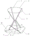
In order to illustrate the principle of astigmatism and stigmation of an electron microscope, the invention provides a device for demonstrating astigmatism and stigmation of an electron microscope, fig. 3 is a structural diagram of a device for demonstrating astigmatism and stigmation of an electron microscope in an embodiment of the invention, and as shown in fig. 3, the device for demonstrating astigmatism and stigmation of an electron microscope comprises: the device comprises a first sagittal plane rod 1, a second sagittal plane rod 2, a first meridian plane rod 3, a second meridian plane rod 4, a top elastic ring 5, a middle elastic ring 6, a bottom elastic ring 7 and a bottom plate 8.
The first sagittal rod 1 and the second sagittal rod 2 are crossed to form a first intersection point; the first meridian plane bar 3 and the second meridian plane bar 4 are crossed to form a second intersection point; two end points of the first sagittal rod 1 and two end points of the second sagittal rod 2 are both positioned on the first plane; two end points of the first meridian plane bar 3 and two end points of the second meridian plane bar 4 are both positioned on the second plane; the first plane and the second plane are perpendicular to each other. According to the invention, a first sagittal plane 1 and a second sagittal plane 2 form a first plane to simulate a sagittal plane in optics, a first meridian plane 3 and a second meridian plane 4 form a meridian plane in second plane to simulate optics, and the first plane and the second plane are mutually vertical, namely the sagittal plane and the meridian plane in simulation optics are mutually vertical; the first intersection point represents a focal point of the sagittal plane, and the second intersection point represents a focal point of the meridional plane. When the astigmatism is absent, the first intersection point is contacted with the second intersection point; when astigmatism occurs, the first intersection point is separated from the second intersection point. The first sagittal plane rod 1, the second sagittal plane rod 2, the first meridian plane rod 3 and the second meridian plane rod 4 are all made of stainless steel or glass fiber reinforced plastics.
The top elastic ring 5 is fixedly connected with the top of the first sagittal plane rod 1, the top of the second sagittal plane rod 2, the top of the first meridian plane rod 3 and the top of the second meridian plane rod 4; the middle elastic ring 6 is fixedly connected with the middle parts of the first sagittal plane rod 1, the second sagittal plane rod 2, the first meridian plane rod 3 and the second meridian plane rod 4; the bottom elastic ring 7 is fixedly connected with the bottom of the first sagittal plane rod 1, the bottom of the second sagittal plane rod 2, the bottom of the first meridian plane rod 3 and the bottom of the second meridian plane rod 4. The top elastic ring 5, the middle elastic ring 6 and the bottom elastic ring 7 are all made of elastic bodies, and the materials with better elasticity and plasticity, such as rubber, are selected to be easy to stretch and contract. The top elastic ring 5, the middle elastic ring 6 and the bottom elastic ring 7 respectively simulate the shape of a focal spot in optics, the first sagittal rod 1 and the second sagittal rod 2 move to represent the movement of a sagittal focal point, and the first meridian rod 3 and the second meridian rod 4 move to represent the movement of a meridian focal point. If the first intersection point and the second intersection point are superposed, the focal lengths of the meridian plane and the sagittal plane are consistent, the focus can be focused on the same point, and no astigmatism is generated; if the first intersection point and the second intersection point are separated to indicate that the focal lengths of the meridian plane and the sagittal plane are not consistent, the focus cannot be on the same point, and astigmatism occurs. Considering the fact that the rod has a certain diameter, the first intersection point and the second intersection point cannot be completely coincident, and the two intersection points are approximately coincident when being contacted.
The lengths of the first sagittal rod 1, the second sagittal rod 2, the first meridian rod 3 and the second meridian rod 4 are all equal. The distance from a fixed point at the top of the top elastic ring 5 and the first sagittal plane rod 1 to the top end of the first sagittal plane rod 1, the distance from a fixed point at the top of the top elastic ring 5 and the second sagittal plane rod 2 to the top end of the second sagittal plane rod 2, the distance from a fixed point at the top of the top elastic ring 5 and the first meridional plane rod 3 to the top end of the first meridional plane rod 3, and the distance from a fixed point at the top of the top elastic ring 5 and the second meridional plane rod 4 to the top end of the second meridional plane rod 4 are equal. Considering the practical situation, if the rods have a certain diameter, the four rods cannot be completely overlapped, and the elastic ring may not be in a regular circle shape, so the elastic ring is approximately regarded as a circle.
The distance from a fixed point in the middle of the middle elastic ring 6 and the first sagittal plane rod 1 to the center point of the first sagittal plane rod 1, the distance from a fixed point in the middle of the middle elastic ring 6 and the second sagittal plane rod 2 to the center point of the second sagittal plane rod 2, the distance from a fixed point in the middle of the middle elastic ring 6 and the first meridian plane rod 3 to the center point of the first meridian plane rod 3, and the distance from a fixed point in the middle of the middle elastic ring 6 and the second meridian plane rod 4 to the center point of the second meridian plane rod 4 are equal.
The distance from a fixed point at the bottom of the bottom elastic ring 7 and the first sagittal plane rod 1 to the bottom of the first sagittal plane rod 1, the distance from a fixed point at the bottom of the bottom elastic ring 7 and the second sagittal plane rod 2 to the bottom of the second sagittal plane rod 2, the distance from a fixed point at the bottom of the bottom elastic ring 7 and the first meridian plane rod 3 to the bottom of the first meridian plane rod 3, and the distance from a fixed point at the bottom of the bottom elastic ring 7 and the second meridian plane rod 4 to the bottom of the second meridian plane rod 4 are equal.
The bottom plate 8 is provided with a first scale groove 9 and a second scale groove 10, the first scale groove 9 and the second scale groove 10 are mutually perpendicular and crossed, the shape is similar to an X type, and the grooves with scales are convenient for observing the sliding distance of sagittal plane rods and meridional plane rods. The bottom plate 8 is made of one of steel, copper and aluminum.
Fig. 4 is a schematic structural view along the direction of the scale groove, and as shown in fig. 4, the device for demonstrating astigmatism and stigmation of the mirror further includes: a first slider 11, a second slider (not shown), a third slider (not shown) and a fourth slider (not shown). First slider 11 and second slider slidable set up in the both sides of first scale recess 9, and the bottom of first sagittal plane pole 1 sets up on first slider 11, and the bottom of second sagittal plane pole 2 sets up on the second slider. The third slider and the fourth slider can be arranged on two sides of the second scale groove 10 in a sliding manner, the bottom end of the first meridian plane rod 3 is arranged on the third slider, and the bottom end of the second meridian plane rod 4 is arranged on the fourth slider. The first slide block 11, the second slide block, the third slide block and the fourth slide block are made of steel or copper. The intersection O of the first scale groove 9 and the second scale groove 10, the central point of the top elastic ring 5, the central point of the middle elastic ring 6 and the central point of the bottom elastic ring 7 are all located on the same straight line.
When the astigmatism is demonstrated, the position without the astigmatism is determined, namely the first intersection point and the second intersection point are superposed, the three elastic rings are all circular at the time, and the radius of the elastic ring at the intersection point is the minimum. Fig. 5 is a schematic diagram of the movement of the rods, assuming that the rod length is L and the distance between the rods of one pair on the base plate 8 is D in the absence of astigmatism, then the rods of one pair (the first meridian rod 3 and the second meridian rod 4 are a pair) move towards each other and move by the distance x at the same time, then the rods of the other pair (the first sagittal rod 1 and the second sagittal rod 2 are another pair) move away from each other and move by the distance x at the same time, and the first intersection point and the second intersection point do not coincide any longer.
As shown in fig. 5, for the sagittal plane, when a rod moves by x horizontal distance, the middle position also moves by x working distance as compared to the non-astigmatic position, and also for the midday plane, so that in the middle position, regardless of the movements of the sagittal and meridional planes, the horizontal section radii are equal, and thus the middle position is also a circle. After the two pairs of rods have moved the same distance, the focal spot at the middle position of the rods remains circular, but increases relative to the absence of astigmatism, which is the distance x of movement. This is consistent with the true astigmatism case, so this model can reasonably simulate the true case. The distance of the top end of the sagittal plane is reduced, the distance of the top end of the meridian plane is increased, the two diameters are different, the elastic ring is in an oval shape, the length of the long side is D +2x, and the length of the short side is D-2 x; the meridian plane is also analyzed, the long side and the short side of the ellipse are the same, and only the direction is vertical to the sagittal plane, which is also consistent with the astigmatism phenomenon.
When there is no astigmatism, the diameter of the top elastic ring 5 and the bottom elastic ring 7 is D, and the perimeter is L0After each rod moves a distance x, according to an ellipse perimeter calculation formula L2 pi b +4(a-b), wherein a and b are the radii of the long side and the short side respectively, and the radii of the long side and the short side (D +2x)/2 and the length of the short side (D-2x)/2 are substituted into the ellipse perimeter calculation formula to obtain LxSince pi D + (8-2 pi) x ≈ pi D +1.72x, the circumference of the elastic ring becomes longer with an increase in x by 1.72x, the elastic ring is made of a material having a small elastic modulus, and a material having a large elastic modulus and not easily elongated cannot be used. Therefore, the elastic ring can be made of materials which have small elastic modulus and are easy to stretch, such as a rubber elastic ring, a thin spring wire and the like, and materials which have large elastic modulus and are difficult to stretch, such as a steel wire, a plastic ring and the like, cannot be selected. For the middle elastic ring 6, it is demonstrated that without astigmatism, assuming a very small diameter C (the line segment in the diagram has no diameter so this diameter is a point, but in practice the rods have a diameter, this elastic ring will certainly be larger than the thickness of the four rods when they intersect), it is demonstrated that with astigmatism and with a movement x the diameter C +2x, the elongation 2x, about 6.28x, is greater, so this elastic ring has a lower modulus of elasticity, is thinner and is more easily deformable.
The invention provides a method for demonstrating astigmatism of an electron microscope, fig. 6 is a flowchart of a method for demonstrating astigmatism of an electron microscope in an embodiment of the invention, fig. 7 is a schematic diagram (without a bottom plate 8) of a device for demonstrating astigmatism of an electron microscope, and as shown in fig. 6, the method for demonstrating astigmatism of an electron microscope comprises the following steps:
step 101: adjusting the demonstration device to be in an astigmatism-free state; the non-astigmatic state is that the lengths of the bottom end of the first sagittal plane rod 1, the bottom end of the second sagittal plane rod 2, the bottom end of the first meridian plane rod 3 and the bottom end of the second meridian plane rod 4 from the intersection points of the first scale groove 9 and the second scale groove 10 are equal, the first intersection points are in contact with the second intersection points, the top elastic ring 5, the middle elastic ring 6 and the bottom elastic ring 7 are circular, which is equivalent to that the lens magnetic field is axially symmetrically distributed, the meridional plane and the sagittal plane are coincident, and the meridional plane focus and the sagittal plane focus are also consistent.
Step 102: the first sagittal rod 1, the second sagittal rod 2, the first meridional rod 3, and the second meridional rod 4 are moved so that the top elastic ring 5 and the bottom elastic ring 7 become elliptical in shape and the first intersection point is separated from the second intersection point, and astigmatism occurs.
Moving the first sagittal rod 1, the second sagittal rod 2, the first meridional rod 3 and the second meridional rod 4 to change the shapes of the top elastic ring 5 and the bottom elastic ring 7 into ellipses, specifically comprising:
the bottom end of the first sagittal rod 1 and the bottom end of the second sagittal rod 2 are reversely moved by the same distance.
The bottom end of the first meridian plane rod 3 and the bottom end of the second meridian plane rod 4 are moved in the same direction for the same distance; the distance between the bottom end of the first meridian plane bar 3 and the bottom end of the second meridian plane bar 4 is equal to the length between the bottom end of the first sagittal plane bar 1 and the bottom end of the second sagittal plane bar 2, and the distance can be read from the first scale groove 9 and the second scale groove 10.
The principle of astigmatism cancellation is the inverse of astigmatism generation, since astigmatism is generated by moving the rod position x, astigmatism cancellation is the situation where all the rods are moved back to a position free of astigmatism. The invention also provides a method for demonstrating astigmatism elimination of an electron microscope, fig. 8 is a flow chart of a method for demonstrating astigmatism elimination of an electron microscope in the embodiment of the invention, and as shown in fig. 8, the method for demonstrating astigmatism elimination of an electron microscope comprises the following steps:
step 201: adjusting the demonstration device to an astigmatic state; the astigmatic state is that the lengths of the bottom end of the first sagittal plane bar 1 and the bottom end of the second sagittal plane bar 2 from the intersection point of the first scale groove 9 and the second scale groove 10 are equal, the lengths of the bottom end of the first meridional plane bar 3 and the bottom end of the second meridional plane bar 4 from the intersection point of the first scale groove 9 and the second scale groove 10 are equal, the lengths of the bottom end of the first sagittal plane bar 1 and the bottom end of the second sagittal plane bar 2 from the intersection point are not equal to the lengths of the bottom end of the first meridional plane bar 3 and the bottom end of the second meridional plane bar 4 from the intersection point, and the first intersection point is separated from the second intersection point.
Step 202: the first sagittal rod 1, the second sagittal rod 2, the first meridional rod 3 and the second meridional rod 4 are moved so that the top elastic ring 5 and the bottom elastic ring 7 are rounded and the first intersection point is in contact with the second intersection point, and the astigmatism phenomenon is eliminated.
Moving the first sagittal rod 1, the second sagittal rod 2, the first meridional rod 3 and the second meridional rod 4 to change the shapes of the top elastic ring 5 and the bottom elastic ring 7 into a circle, specifically comprising:
the bottom end of the first sagittal plane rod 1, the bottom end of the second sagittal plane rod 2, the bottom end of the first meridian plane rod 3 and the bottom end of the second meridian plane rod 4 are moved, so that the lengths of the bottom end of the first sagittal plane rod 1, the bottom end of the second sagittal plane rod 2, the bottom end of the first meridian plane rod 3 and the bottom end of the second meridian plane rod 4 from the intersection point of the first scale groove 9 and the second scale groove 10 are equal.
The embodiment of the invention can be designed more, such as adding a synchronous mechanism or an automatic mechanism, and through the combination of gears and pulleys, the operation can be carried out once, so that 4 rods can move a specific distance as required. In order to prevent the rod and the slider from falling down when moving or being fixed, the groove shown in fig. 4 may be changed into a T-shaped groove or a dovetail groove. In order to prevent the four rods from being clamped in a staggered mode and to achieve a better demonstration effect, the selected rods are small in diameter (for example, 1-3 mm), the cross sections of the rods are not necessarily circular, and the rods can be rectangular or other figures to facilitate movement of the rods. For example, in order to better coincide four rods during demonstration, according to the shape of the rods shown in fig. 9, the four rods are all in a zigzag shape, the upper end rod and the lower end rod of each rod are connected through the middle rod, the upper end rod and the lower end rod are parallel to each other, the middle rod and the bottom plate 8 are kept parallel, the top elastic rings are respectively in contact with the upper end rods of the four rods, the middle elastic rubber rings are respectively in contact with the lower end rods of the four rods, and the bottom elastic rings are respectively in contact with the lower end rods of the four rods. FIG. 10 is a schematic structural diagram of a rod of another demonstration apparatus for demonstrating astigmatism and astigmatism of an electron microscope according to an embodiment of the invention.
The invention expresses whether the astigmatism exists or not and the severity degree by the distance of four rods and two intersection points of the meridian plane and the sagittal plane, and the method is simple, intuitive and understandable. The shape of the focal spot is represented by the elastic ring on each rod, which is very clear and intuitive. The four rods and the base are compact and easy to carry, and have no requirement on the field, and because an optical device is not used, the field is bright. The demonstration device not only can demonstrate the generation of astigmatism, but also can demonstrate the process of eliminating astigmatism, and is relatively comprehensive, simple in operation, convenient to prepare, few in steps and good in demonstration effect. In addition, the invention can process the physical model without too much material and cost, thus saving the cost.
The principles and embodiments of the present invention have been described herein using specific examples, which are provided only to help understand the method and the core concept of the present invention; meanwhile, for a person skilled in the art, according to the idea of the present invention, the specific embodiments and the application range may be changed. In view of the above, the present disclosure should not be construed as limiting the invention.