The present application is based on Japanese patent application No. 2017-7514, filed on 19.1.2017, the contents of which are incorporated herein by reference.
Detailed Description
Hereinafter, a valve timing adjusting apparatus according to a plurality of embodiments of the present disclosure will be described with reference to the drawings. In addition, substantially the same components in the embodiments are denoted by the same reference numerals, and description thereof is omitted.
(embodiment 1)
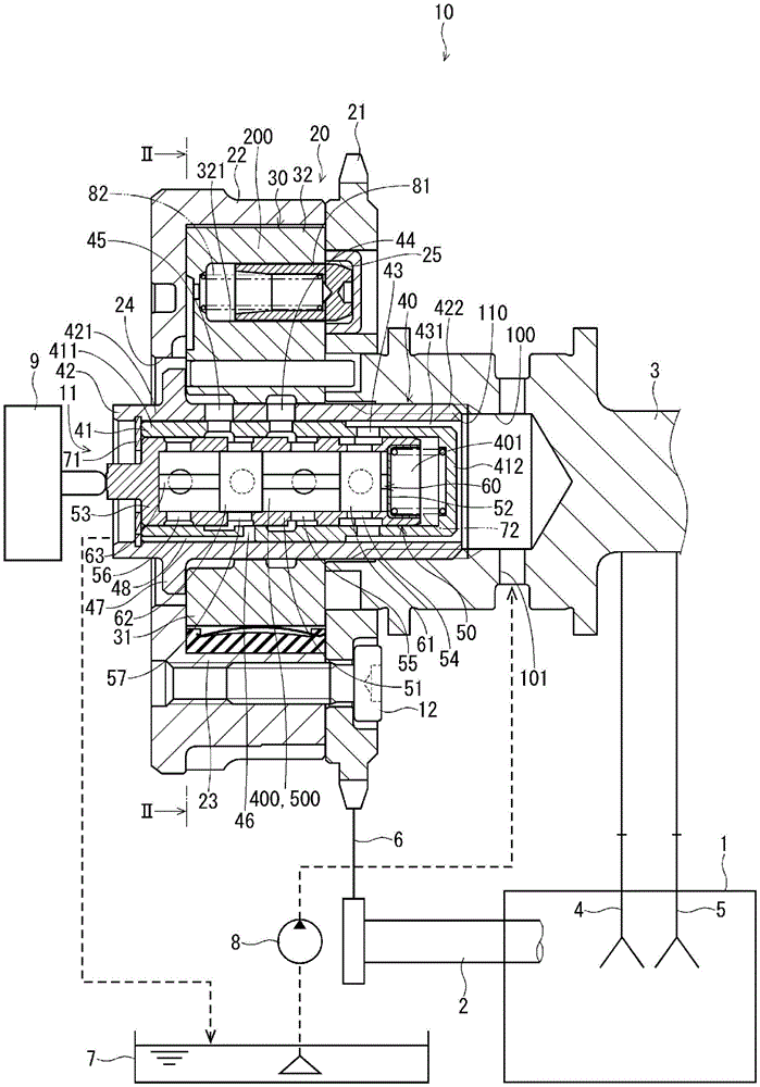
Fig. 1 shows a valve timing adjustment device according to embodiment 1 of the present disclosure. The valve timing adjusting apparatus 10 adjusts the valve timing of the intake valve 4 or the exhaust valve 5 driven to open and close the camshaft 3 by changing the rotational phase of the camshaft 3 with respect to the crankshaft 2 of the engine 1 as an internal combustion engine. The valve timing adjusting apparatus 10 is provided in a power transmission path from the crankshaft 2 to the camshaft 3. The crankshaft 2 corresponds to a "drive shaft". The camshaft 3 corresponds to a "driven shaft".
The structure of the valve timing adjusting apparatus 10 will be described with reference to fig. 1 and 2.
The valve timing adjusting apparatus 10 includes a housing 20, a vane rotor 30, and an oil passage switching valve 11.
The housing 20 is composed of a sprocket 21 and a case 22. The sprocket 21 is fitted to an end of the camshaft 3. The camshaft 3 rotatably supports the sprocket 21. The chain 6 is wound around the sprocket 21 and the crankshaft 2. The sprocket 21 rotates in conjunction with the crankshaft 2. The case 22 has a bottomed cylindrical shape, and an open end is combined with the sprocket 21 and fixed to the sprocket 21 by the bolt 12. The housing 22 forms a plurality of partition wall portions 23 that protrude radially inward. An opening 24 that opens into a space outside the housing 22 is formed in the center of the bottom of the housing 22. The opening 24 is located on the opposite side of the camshaft 3 from the vane rotor 30.
The vane rotor 30 has a boss 31 and a plurality of vanes 32. The boss 31 is cylindrical and fixed to an end of the camshaft 3. The vanes 32 project radially outward from the boss 31 between the partition wall portions 23. The internal space 200 of the housing 20 is partitioned by the vane 32 into a retard chamber 201 and an advance chamber 202. The retard chamber 201 corresponds to the "1 st hydraulic chamber" and is located in one of the circumferential directions with respect to the vane 32. The advance chamber 202 corresponds to the "2 nd hydraulic chamber" and is located on the other side in the circumferential direction with respect to the vane 32. The vane rotor 30 rotates relative to the housing 20 in the retard direction or the advance direction in accordance with the hydraulic pressures of the retard chamber 201 and the advance chamber 202.
The oil passage switching valve 11 includes a sleeve 40, a spool 50, and a check valve 60.
The sleeve 40 has an inner sleeve 41, an outer sleeve 42, a supply port 43, a 1 st control port 44, a 2 nd control port 45, a discharge port 46, and a locking portion 47.
The inner sleeve 41 is formed of a relatively low-hardness metal such as aluminum. The inner sleeve 41 has a sleeve barrel portion 411 and a sleeve bottom portion 412. The sleeve tube 411 is formed in a substantially cylindrical shape. The sleeve bottom portion 412 is formed integrally with the sleeve tube portion 411 so as to close one end portion of the sleeve tube portion 411.
The outer sleeve 42 is formed of metal such as iron. The outer sleeve 42 has a sleeve cylinder 421 and a threaded portion 422. The sleeve tube 421 is formed in a substantially cylindrical shape. The screw portion 422 is formed on the outer wall of one end of the sleeve tube portion 421.
The inner sleeve 41 is provided inside the outer sleeve 42 such that the sleeve bottom portion 412 faces the screw portion 422. Here, the outer wall of the inner sleeve 41 is fitted to the inner wall of the outer sleeve 42. A substantially cylindrical inner space 400 is formed inside the sleeve tube portion 411 of the inner sleeve 41 inside the sleeve tube portion 421 of the outer sleeve 42.
The supply port 43 is formed to connect the outer wall and the inner wall of the sleeve tube 411 of the inner sleeve 41. The outer diameter of the end portion of the sleeve tube portion 411 of the inner sleeve 41 on the sleeve bottom portion 412 side is set smaller than the inner diameter of the sleeve tube portion 421. Thus, an annular oil passage 431, which is an annular oil passage, is formed between the outer wall of the sleeve cylinder 411 and the inner wall of the sleeve cylinder 421. The inner space 400 communicates with the space outside the sleeve 40 via the supply port 43 and the annular oil passage 431.
The 1 st control port 44 is formed to connect an outer wall of the sleeve tube portion 421 of the outer sleeve 42 and an inner wall of the sleeve tube portion 411 of the inner sleeve 41. The 1 st control port 44 is formed in plurality in the circumferential direction of the sleeve 40.
The 2 nd control port 45 is formed to connect the outer wall of the sleeve tube portion 421 of the outer sleeve 42 and the inner wall of the sleeve tube portion 411 of the inner sleeve 41. The 2 nd control port 45 is formed in plurality in the circumferential direction of the sleeve 40.
The supply port 43, the 1 st control port 44, and the 2 nd control port 45 are formed so as to be arranged at a predetermined interval in order from one end side to the other end side of the sleeve 40.
The discharge port 46 is formed to connect the outer wall and the inner wall of the sleeve cylinder portion 411 of the inner sleeve 41.
The sleeve cylindrical portion 411 of the inner sleeve 41 is formed with a sleeve internal oil passage 48. The sleeve-inside oil passage 48 is formed to be recessed radially inward from the outer wall of the sleeve cylindrical portion 411 and to extend from the discharge port 46 in the axial direction of the sleeve cylindrical portion 411. Therefore, in a state where the inner sleeve 41 is disposed inside the outer sleeve 42, the sleeve internal oil passage 48 is formed between the inner sleeve 41 and the outer sleeve 42, that is, in the thickness (wall thickness) of the sleeve 40.
The discharge port 46 communicates with the side opposite to the camshaft 3 with respect to the oil passage switching valve 11, that is, the outside of the valve timing adjusting apparatus 10, via the sleeve-inside oil passage 48.
The locking portion 47 is formed in a ring shape so as to protrude radially outward from the outer wall of the other end portion side of the sleeve tube portion 421.
A shaft hole 100 and a supply hole 101 are formed in the end of the camshaft 3 on the valve timing adjusting device 10 side. The shaft hole portion 100 is formed to extend from the center of the end surface of the camshaft 3 on the valve timing adjustment device 10 side along the axial direction of the camshaft 3. The supply hole portion 101 is formed to extend radially inward from the outer wall of the camshaft 3 and communicates with the shaft hole portion 100.
An axial-side threaded portion 110 that can be screwed to the threaded portion 422 of the sleeve 40 is formed on the inner wall of the axial hole portion 100 of the camshaft 3.
The sleeve 40 is fixed to the camshaft 3 by the screw portion 422 being coupled to the shaft-side screw portion 110 of the camshaft 3 through the inside of the boss 31 of the vane rotor 30. At this time, the locking portion 47 of the sleeve 40 locks the end surface of the boss 31 of the vane rotor 30 on the side opposite to the camshaft 3. Thereby, the vane rotor 30 is fixed to the camshaft 3 so as to be sandwiched between the camshaft 3 and the locking portion 47. Thus, the sleeve 40 is provided at the center portion of the vane rotor 30.
The oil pump 8 is connected to the supply hole 101. The oil pump 8 pumps up the hydraulic oil stored in the oil pan 7 and supplies the hydraulic oil to the supply hole 101. Thereby, the working oil flows into the shaft hole portion 100. Here, the oil pump 8 corresponds to a "working oil supply source".
The hydraulic oil flowing into the shaft hole 100 flows into the inner space 400 through the annular oil passage 431 and the supply port 43.
Further, in a state where the sleeve 40 is provided at the center portion of the vane rotor 30, the 1 st control port 44 communicates with the retard chamber 201 via a retard oil passage 301 formed in the boss 31. Further, the 2 nd control port 45 communicates with the advance chamber 202 via an advance oil passage 302 formed in the boss 31.
The spool 50 has a spool cylindrical portion 51, a spool lid portion 52, a spool bottom portion 53, a supply oil passage 54, a 1 st control oil passage 55, a 2 nd control oil passage 56, and a recirculation oil passage 57.
The spool tube 51 is formed in a substantially cylindrical shape. The spool lid 52 is provided to close one end of the spool cylinder 51. In the present embodiment, the spool lid portion 52 is formed separately from the spool tube portion 51. The spool bottom portion 53 is formed integrally with the spool tubular portion 51 so as to close the other end portion of the spool tubular portion 51. A substantially cylindrical pressure accumulation space 500 is formed between the inner wall of the spool tube 51, the spool lid 52, and the spool bottom 53.
The supply oil passage 54 is formed to connect an annular recess formed in the outer wall of the spool cylindrical portion 51 to the inner wall of the spool cylindrical portion 51. The supply oil passage 54 is formed in plurality in the circumferential direction of the spool 50.
The 1 st control oil passage 55 is formed to connect an annular recess formed in the outer wall of the spool cylindrical portion 51 to the inner wall of the spool cylindrical portion 51. The 1 st control oil passage 55 is formed in plurality in the circumferential direction of the spool 50.
The 2 nd control oil passage 56 is formed to connect an annular recess formed in the outer wall of the spool cylindrical portion 51 to the inner wall of the spool cylindrical portion 51. The 2 nd control oil passage 56 is formed in plurality in the circumferential direction of the spool 50.
The recirculation oil passage 57 is formed to connect an annular recess formed in the outer wall of the spool cylinder 51 to the inner wall of the spool cylinder 51. The recirculation oil passage 57 is formed in plurality in the circumferential direction of the spool 50.
The supply oil passage 54, the 1 st control oil passage 55, the recirculation oil passage 57, and the 2 nd control oil passage 56 are formed in a row with a predetermined interval in order from one end side to the other end side of the spool 50.
The spool 50 is provided in the inner space 400, which is the inner side of the sleeve 40, such that the spool lid portion 52 faces the sleeve bottom portion 412. The spool 50 is capable of reciprocating in the axial direction in the inner space 400.
The engagement portion 71 is provided on the side of the spool tube portion 51 opposite to the sleeve bottom portion 412. The locking portion 71 is formed in an annular shape, and is provided so that an outer edge portion thereof fits into an inner wall of the outer sleeve 42. The locking portion 71 can lock an end of the spool tubular portion 51 opposite to the spool bottom 53. This prevents the spool 50 from being pulled out to the opposite side of the sleeve bottom portion 412.
The spool 50 forms a variable volume space 401 between the spool lid portion 52 and the sleeve bottom portion 412 in the inner space 400 of the sleeve 40. When the spool 50 reciprocates in the axial direction, the volume of the volume-variable space 401 changes.
A spring 72 is disposed between the spool cover 52 and the sleeve bottom 412. The spring 72 biases the spool 50 toward the locking portion 71. Thereby, the spool 50 is pressed against the locking portion 71.
A linear solenoid 9 is provided on the side of the spool 50 opposite to the camshaft 3. The linear solenoid 9 is energized to press the spool 50 toward the camshaft 3 against the urging force of the spring 72. Thereby, the position of the spool 50 in the axial direction with respect to the sleeve 40 changes. The movable range of the spool 50 is from a position where the spool 50 abuts against the locking portion 71 to a position where the spool 50 abuts against the sleeve bottom portion 412.
The supply oil passage 54 communicates with the supply port 43 regardless of the position of the spool 50 in the axial direction with respect to the sleeve 40.
When the spool 50 is positioned in contact with the engagement portion 71 (see fig. 1), the 1 st control oil passage 55 communicates with the 1 st control port 44, and the 2 nd control port 45 communicates with the recirculation oil passage 57. Thereby, the oil pump 8 is connected to the retard chamber 201, and the advance chamber 202 is connected to the recirculation oil passage 57.
When the spool 50 is in a position abutting the sleeve bottom portion 412, the 2 nd control oil passage 56 communicates with the 2 nd control port 45, and the 1 st control port 44 communicates with the recirculation oil passage 57. Thereby, the oil pump 8 is connected to the advance chamber 202, and the retard chamber 201 is connected to the recirculation oil passage 57.
When the spool 50 is located at an intermediate position between the engagement portion 71 and the sleeve bottom portion 412, the 1 st control oil passage 55, the recirculation oil passage 57, and the 2 nd control oil passage 56 are blocked from the 1 st control port 44 and the 2 nd control port 45. Thereby, both the retard chamber 201 and the advance chamber 202 are closed.
As shown in fig. 3, the check valve 60 includes a supply check valve 61, a recirculation check valve 62, and a shaft 63.
The check valve 60 is formed by winding a thin metal plate 600 shown in fig. 3C, for example. The sheet 600 has a supply check valve corresponding portion 601, a recirculation check valve corresponding portion 602, and a shaft portion corresponding portion 603. The supply check valve corresponding portion 601, the recirculation check valve corresponding portion 602, and the shaft portion corresponding portion 603 are formed in a rectangular plate shape. The supply check valve corresponding portion 601 and the recirculation check valve corresponding portion 602 are formed integrally with the shaft portion corresponding portion 603 so as to extend from the longitudinal side of the shaft portion corresponding portion 603 in the short side direction. The check valve 60 is formed by winding the shaft portion corresponding portion 603, the supply check valve corresponding portion 601, and the recirculation check valve corresponding portion 602 in the short side direction of the shaft portion corresponding portion 603.
The shaft portion 63 is formed in a substantially cylindrical shape (see fig. 3A and 3B). In the shaft portion 63, the plate materials, i.e., the shaft portion corresponding portions 603 do not overlap each other in the circumferential direction.
The supply check valve 61 is formed in a substantially cylindrical shape so as to extend radially outward from the vicinity of one end of the shaft portion 63 and surround the periphery of the shaft portion 63 by 1 circumference (see fig. 3A and 3B). Thereby, the supply check valve 61 is formed to be elastically deformable in the radial direction. When the supply check valve 61 is deformed inward in the radial direction, the outer diameter is reduced. More specifically, the supply check valve 61 has a portion where the plate materials, i.e., the supply check valve corresponding portions 601 overlap each other in the circumferential direction. The overlap increases, deforms radially inward and contracts radially, and decreases, deforming radially outward and expanding radially. The space inside the substantially cylindrical supply check valve 61 is open in the axial direction of the check valve 60.
The recirculation check valve 62 is formed in a substantially cylindrical shape so as to extend radially outward from the shaft portion 63 and surround the circumference of the shaft portion 63 by 1 circumference (see fig. 3A and 3B). Thereby, the recirculation check valve 62 is formed to be elastically deformable in the radial direction. The recirculation check valve 62, when deformed radially inward, reduces in outer diameter. More specifically, the recirculation check valve 62 has a portion where the plate materials, i.e., the recirculation check valve corresponding portions 602, overlap each other in the circumferential direction (see fig. 3B). The overlap increases, deforms radially inward and contracts radially, and decreases, deforming radially outward and expanding radially. The space inside the recirculation check valve 62 formed in a substantially cylindrical shape is open in the axial direction of the check valve 60.
The check valve 60 is provided in the pressure accumulation space 500 such that the supply check valve 61 corresponds to the supply oil passage 54 and the recirculation check valve 62 corresponds to the recirculation oil passage 57 (see fig. 1 and 4). The shaft portion 63 is located between the spool lid portion 52 and the spool bottom portion 53, and supports the supply check valve 61 and the recirculation check valve 62.
When the hydraulic oil flows from the supply oil passage 54 side toward the pressure accumulation space 500 side, the outer peripheral surface of the supply check valve 61 is pressed by the hydraulic oil, whereby the supply check valve 61 is deformed radially inward and opens, and a gap is formed between the inner wall of the spool 50 and the supply check valve 61. Thereby, the hydraulic oil can flow into the pressure accumulation space 500 through the supply oil passage 54. On the other hand, when the working oil flows from the pressure accumulation space 500 side to the supply oil passage 54 side, the inner surface of the supply check valve 61 is pressed by the working oil, and the supply check valve 61 is deformed outward in the radial direction to close the valve, and sticks to the inner wall of the spool 50 to block the supply oil passage 54. This restricts the flow of the hydraulic oil from the pressure accumulation space 500 to the outside of the spool 50 through the supply oil passage 54. Thus, the supply check valve 61 allows the working oil to flow from the supply oil passage 54 side toward the pressure accumulation space 500 side, and restricts the working oil from flowing from the pressure accumulation space 500 side toward the supply oil passage 54 side.
When the hydraulic oil moves from the recirculation oil passage 57 side to the pressure accumulation space 500 side, the outer peripheral surface of the recirculation check valve 62 is pressed by the hydraulic oil, whereby the recirculation check valve 62 is deformed radially inward and opened, and a gap is formed between the inner wall of the spool 50 and the recirculation check valve 62. Thereby, the working oil can flow into the pressure accumulation space 500 via the recirculation oil passage 57. On the other hand, when the hydraulic oil flows from the pressure accumulation space 500 side toward the recirculation oil passage 57 side, the inner peripheral surface of the recirculation check valve 62 is pressed by the hydraulic oil, whereby the recirculation check valve 62 is deformed radially outward to close the valve, and sticks to the inner wall of the spool 50 to block the recirculation oil passage 57. This restricts the flow of the working oil from the pressure accumulation space 500 to the outside of the spool 50 via the recirculation oil passage 57. Thus, the recirculation check valve 62 allows the working oil to flow from the recirculation oil passage 57 side toward the pressure accumulation space 500 side, and restricts the working oil from flowing from the pressure accumulation space 500 side toward the recirculation oil passage 57 side.
As shown in fig. 4, the recirculation oil passage 57 and the drain port 46 are connected to each other inside the sleeve 40. More specifically, the recirculation oil passage 57 and the drain port 46 are connected to each other in an annular recess 501 formed in the outer wall of the spool cylinder 51.
Further, the drain port 46 is formed in the sleeve 40 so as to be located at least partially radially outward of the spool 50 with respect to the recirculation oil passage 57. More specifically, the drain port 46 is formed such that at least a portion thereof is located radially outward of the spool 50 with respect to the recirculation oil passage 57, regardless of whether the spool 50 is located in a position abutting against the locking portion 71 (see fig. 1) or the spool 50 is located in a position abutting against the sleeve bottom portion 412, in the sleeve 40.
When the spool 50 is positioned in abutment with the locking portion 71, the recessed portion 501 communicates the 2 nd control port 45 with the recirculation oil passage 57. When the spool 50 is positioned in abutment with the sleeve bottom portion 412, the recess 501 communicates the 1 st control port 44 with the recirculation oil passage 57.
In the present embodiment, when the spool 50 is positioned in contact with the locking portion 71 (see fig. 1), the working oil is supplied to the retard chamber 201 through the 1 st control port 44, and the working oil in the advance chamber 202 flows to the recess 501 through the 2 nd control port 45. A part of the working oil flowing in the recess 501 is returned to the pressure accumulation space 500 via the recirculation oil passage 57 and the recirculation check valve 62. Further, a part of the working oil flowing in the recess 501 is discharged to the outside of the valve timing adjusting apparatus 10 via the discharge port 46 and the sleeve inner oil passage 48.
When the spool 50 is positioned in contact with the sleeve bottom portion 412, the working oil is supplied to the advance chamber 202 via the 2 nd control port 45, and the working oil in the retard chamber 201 flows to the recess 501 via the 1 st control port 44. A part of the working oil flowing in the recess 501 is returned to the pressure accumulation space 500 via the recirculation oil passage 57 and the recirculation check valve 62. Further, a part of the working oil flowing in the recess 501 is discharged to the outside of the valve timing adjusting apparatus 10 via the discharge port 46 and the sleeve inner oil passage 48.
The oil passage switching valve 11 is operated in a 1 st operation state in which the oil pump 8 is connected to the retard chamber 201 and the advance chamber 202 is connected to the recirculation oil passage 57, a 2 nd operation state in which the oil pump 8 is connected to the advance chamber 202 and the retard chamber 201 is connected to the recirculation oil passage 57, and a holding state in which the retard chamber 201 and the advance chamber 202 are simultaneously closed by pressing the spool 50 by driving the linear solenoid 9. In the 1 st operating state, the working oil is returned from the advance chamber 202 to the pressure accumulation space 500 while being supplied to the retard chamber 201. In the 2 nd operation state, the working oil is returned from the retard chamber 201 to the pressure accumulation space 500 while being supplied to the advance chamber 202. In the holding state, the working oil in the retard chamber 201 and the advance chamber 202 is held.
The present embodiment further includes a locking pin 81 (see fig. 1 and 2). The lock pin 81 is formed in a bottomed cylindrical shape and is housed in a housing hole 321 formed in the vane 32 so as to be capable of reciprocating in the axial direction. A spring 82 is provided inside the locking pin 81. The spring 82 biases the lock pin 81 toward the sprocket 21. The sprocket 21 has an insertion recess 25 formed on the blade 32 side.
When the vane rotor 30 is located at the most retarded angle position with respect to the housing 20, the lock pin 81 can be fitted into the fitting recess 25. When the locking pin 81 is fitted into the fitting recess 25, the relative rotation of the vane rotor 30 with respect to the housing 20 is restricted. On the other hand, when the lock pin 81 is not fitted into the fitting recess 25, relative rotation of the vane rotor 30 with respect to the housing 20 is permitted.
A pin control oil passage 303 communicating with the retard chamber 201 is formed between the lock pin 81 of the vane 32 and the retard chamber 201. Further, a pin control oil passage 304 (see fig. 2) communicating with the advance chamber 202 is formed between the lock pin 81 of the vane 32 and the advance chamber 202. The pressure of the hydraulic oil flowing from the retard chamber 201 or the advance chamber 202 into the pin control oil passages 303 and 304 acts in a direction in which the lock pin 81 is pulled out from the fit-in recessed portion 25 against the biasing force of the spring 82.
In the valve timing adjusting apparatus 10 configured as described above, when the hydraulic oil is supplied to the retard chamber 201 or the advance chamber 202, the hydraulic oil flows into the pin control oil passages 303 and 304, the lock pin 81 is pulled out from the fitting recess 25, and the vane rotor 30 is allowed to rotate relative to the housing 20.
The valve timing adjusting apparatus 10 sets the oil passage switching valve 11 to the 1 st operation state when the rotational phase of the camshaft 3 is at the advanced angle side from the target value. Thereby, the vane rotor 30 rotates relative to the housing 20 in the retard direction, and the rotational phase of the camshaft 3 changes toward the retard side.
Further, the valve timing adjusting apparatus 10 sets the oil passage switching valve 11 to the 2 nd operation state when the rotational phase of the camshaft 3 is at the retarded side from the target value. Thereby, the vane rotor 30 is relatively rotated in the advance angle direction with respect to the housing 20, and the rotational phase of the camshaft 3 is changed to the advance angle side.
Further, the valve timing adjusting apparatus 10 sets the oil passage switching valve 11 in the holding state when the rotational phase of the camshaft 3 coincides with the target value. Thereby, the rotational phase of the camshaft 3 is maintained.
As described above, the present embodiment provides a valve timing adjustment device 10 that is provided in a power transmission path through which power is transmitted from a crankshaft 2 to a camshaft 3 of an engine 1, adjusts the valve timing of an intake valve 4 that is driven by opening and closing the camshaft 3, and includes a housing 20, a vane rotor 30, a sleeve 40, a spool 50, and a recirculation check valve 62.
When one of the crankshaft 2 and the camshaft 3 is the 1 st shaft and the other of the crankshaft 2 and the camshaft 3 is the 2 nd shaft, the housing 20 rotates in conjunction with the 1 st shaft, fits into an end of the 2 nd shaft, and is rotatably supported by the 2 nd shaft.
The vane rotor 30 is fixed to an end of the 2 nd shaft, and has vanes 32 that partition an internal space 200 of the housing 20 into a retard chamber 201 on one side in the circumferential direction and an advance chamber 202 on the other side in the circumferential direction, and the vane rotor 30 rotates relative to the housing 20 in accordance with the pressure of the working oil supplied from the oil pump 8 to the retard chamber 201 and the advance chamber 202.
The sleeve 40 is formed in a tubular shape, and has a supply port 43 communicating with the oil pump 8, a 1 st control port 44 communicating with the retard chamber 201, a 2 nd control port 45 communicating with the advance chamber 202, and a drain port 46 communicating with the outside of the valve timing adjusting apparatus 10.
The spool 50 is formed in a cylindrical shape, is disposed inside the sleeve 40 so as to be capable of reciprocating in the axial direction, and has a pressure accumulation space 500 formed inside, a supply oil passage 54 formed to connect the pressure accumulation space 500 to the supply port 43, a 1 st control oil passage 55 formed to be capable of connecting the pressure accumulation space 500 to the 1 st control port 44, a 2 nd control oil passage 56 formed to be capable of connecting the pressure accumulation space 500 to the 2 nd control port 45, and a recirculation oil passage 57 formed to be capable of connecting the 1 st control port 44 or the 2 nd control port 45 to the pressure accumulation space 500. The working oil from the retard chamber 201 and the advance chamber 202 can be reused through the recirculation oil passage 57.
The recirculation check valve 62 is provided inside the spool 50, allows the working oil to flow from the recirculation oil passage 57 side toward the pressure accumulation space 500 side, and restricts the working oil from flowing from the pressure accumulation space 500 side toward the recirculation oil passage 57 side. Therefore, the backflow of the working oil from the pressure accumulation space 500 side to the recirculation oil passage 57 side can be suppressed. This can improve the response of the valve timing adjusting apparatus 10 in a configuration in which the hydraulic oil can be reused.
In the present embodiment, the recirculation oil passage 57 and the drain port 46 are connected to each other inside the sleeve 40. Therefore, unlike the conventional art, it is not necessary to form a port different from the drain port 46 in the sleeve 40, and the port is a recirculation port for returning the working oil from each hydraulic chamber to the pressure accumulation space. This can reduce the axial dimension of the sleeve 40, and can reduce the size of the oil passage switching valve 11.
In the present embodiment, the drain port 46 is formed so that at least a part thereof is located radially outward of the spool 50 with respect to the recirculation oil passage 57. Therefore, the axial dimensions of the sleeve 40 and the spool 50 can be reduced.
In the present embodiment, the recirculation oil passage 57 is formed between the 1 st control oil passage 55 and the 2 nd control oil passage 56 in the axial direction of the sleeve 40. Therefore, the working oil from the retard chambers 201 and the advance chambers 202 can be returned to the accumulator space 500 via the single recirculation oil passage 57. Further, one recirculation check valve 62 is sufficient.
In the present embodiment, the discharge port 46 communicates with the outside of the valve timing adjusting apparatus 10 via an in-sleeve oil passage 48, which is an oil passage formed in the wall thickness of the sleeve 40. Therefore, the path length of the exhaust port 46 from the outside of the valve timing adjusting apparatus 10 can be shortened.
In the present embodiment, the recirculation check valve 62 is formed to be elastically deformable in the radial direction of the spool 50. Therefore, the recirculation check valve 62 can be simply formed by a thin plate or the like.
In the present embodiment, the sleeve 40 is disposed in the center of the vane rotor 30. That is, in the present embodiment, the sleeve 40 and the spool 50 constituting the oil passage switching valve 11 are provided in the center portion of the vane rotor 30. This shortens the oil path between the oil path switching valve 11 and the retard chamber 201 and the advance chamber 202, thereby improving the responsiveness of the valve timing adjusting apparatus 10.
(embodiment 2)
Fig. 5 shows a valve timing adjustment device according to embodiment 2 of the present disclosure. The sleeve 40, the spool 50, the check valve 60, the vane rotor 30, and the camshaft 3 according to embodiment 2 are different from those according to embodiment 1.
The sleeve 40 is formed of a metal such as iron. The sleeve 40 has a sleeve barrel 451, a sleeve bottom 452, and a screw portion 453.
The sleeve barrel portion 451 is formed in a substantially cylindrical shape. The sleeve bottom portion 452 is formed integrally with the sleeve tube portion 451 so as to close one end portion of the sleeve tube portion 451. The threaded portion 453 is formed on the outer wall of the end portion of the sleeve barrel portion 451 on the sleeve bottom portion 452 side.
The sleeve 40 is fixed to the camshaft 3 by the screw portion 453 being coupled to the shaft-side screw portion 110 of the camshaft 3 through the inside of the boss 31 of the vane rotor 30.
A breathing hole 402 is formed in the sleeve bottom 452. The breathing hole 402 is formed to penetrate the center of the sleeve bottom 452 in the plate thickness direction. That is, the breathing hole 402 is connected to the volume-variable space 401.
The camshaft 3 is formed with an external communication hole 102. The exterior communication hole 102 is formed to communicate the shaft hole portion 100 with the exterior of the camshaft 3. Therefore, the volume-variable space 401 communicates with the outside of the camshaft 3, i.e., the atmosphere, via the breathing hole 402, the shaft hole portion 100, and the external communication hole 102. This makes it possible to equalize the pressure in the volume-variable space 401 with the atmospheric pressure. In the present embodiment, since the pressure in the variable volume space 401 is equalized to the atmospheric pressure by the breathing hole 402 and the external communication hole 102, when the linear solenoid 9 presses the spool 50, the spool 50 can smoothly reciprocate in the axial direction inside the sleeve 40.
The spool lid portion 52 is formed integrally with the spool cylinder portion 51. The spool bottom 53 is formed separately from the spool tube 51 and is press-fitted into an end of the spool tube 51 opposite to the spool lid 52.
In the present embodiment, the spool 50 has recirculation oil passages 571 and 572 instead of the recirculation oil passage 57.
The recirculation oil passage 571 is formed by connecting an annular recess formed in the outer wall of the spool tube 51 to the inner wall of the spool tube 51 on the side opposite to the spool lid 52 with respect to the supply oil passage 54. The recirculation oil passage 571 is formed in plurality in the circumferential direction of the spool 50.
The recirculation oil passage 572 is formed to connect an annular recess formed in the outer wall of the spool cylinder 51 to the inner wall of the spool cylinder 51 on the side opposite to the spool lid 52 with respect to the recirculation oil passage 571. The recirculation oil passage 572 is formed in plurality in the circumferential direction of the spool 50.
In the present embodiment, the 1 st control oil passage 55 and the 2 nd control oil passage 56 are integrally formed between the recirculation oil passage 571 and the recirculation oil passage 572.
In the present embodiment, the discharge port 46 is formed between the supply port 43 and the 1 st control port 44. The drain port 46 is formed in the sleeve 40 so as to be located at least partially radially outward of the spool 50 with respect to the recirculation oil passage 571. More specifically, the drain port 46 is formed in the sleeve 40 such that at least a portion thereof is positioned radially outward of the spool 50 with respect to the recirculation oil passage 571, regardless of whether the spool 50 is positioned in abutment with the locking portion 71 (see fig. 5) or the spool 50 is positioned in abutment with the sleeve bottom portion 452. The recirculation oil path 571 and the drain port 46 are connected to each other inside the sleeve 40.
A sleeve outer oil passage 103 is formed radially outside the sleeve 40 with respect to the discharge port 46 of the camshaft 3. Further, a sleeve outer oil passage 33 penetrating the boss 31 in the plate thickness direction is formed in the boss 31 of the vane rotor 30. The discharge port 46 communicates with the sleeve-outside oil passage 103 and the sleeve-outside oil passage 33. Therefore, the discharge port 46 communicates with the boss 31 on the side opposite to the camshaft 3, that is, the outside of the valve timing adjusting apparatus 10, via the sleeve outer oil passage 103 and the sleeve outer oil passage 33.
In addition, the sleeve 40 has a drain 49. The drain port 49 is formed in the sleeve 40 so as to be located at least partially radially outward of the spool 50 with respect to the recirculation oil passage 572. More specifically, the drain port 49 is formed in the sleeve 40 such that at least a part thereof is located radially outward of the spool 50 with respect to the recirculation oil passage 572, regardless of whether the spool 50 is located in a position abutting against the locking portion 71 or the spool 50 is located in a position abutting against the sleeve bottom portion 452. The recirculation oil passage 572 and the drain 49 are connected to each other inside the sleeve 40.
The drain port 49 communicates with the side opposite to the camshaft 3 with respect to the oil passage switching valve 11, that is, the outside of the valve timing adjusting apparatus 10.
In the present embodiment, the check valve 60 has recirculation check valves 621, 622 instead of the recirculation check valve 62.
The recirculation check valves 621 and 622 have the same configuration as the recirculation check valve 62, and therefore, the description thereof is omitted.
The check valve 60 is provided in the pressure accumulation space 500 such that the supply check valve 61 corresponds to the supply oil passage 54, the recirculation check valve 621 corresponds to the recirculation oil passage 571, and the recirculation check valve 622 corresponds to the recirculation oil passage 572.
When the working oil flows from the recirculation oil passages 571 and 572 to the pressure accumulation space 500, the recirculation check valves 621 and 622 are deformed radially inward, and gaps are formed between the inner wall of the spool 50 and the recirculation check valves 621 and 622. Thereby, the hydraulic oil can flow into the pressure accumulation space 500 through the recirculation oil passages 571 and 572. On the other hand, when the working oil flows from the pressure accumulation space 500 side to the recirculation oil passages 571 and 572 side, the recirculation check valves 621 and 622 deform outward in the radial direction and adhere to the inner wall of the spool 50 to block the recirculation oil passages 571 and 572. This restricts the working oil from flowing out of the accumulator space 500 to the outside of the spool 50 through the recirculation oil passages 571 and 572. Thus, the recirculation check valves 621 and 622 allow the hydraulic oil to flow from the recirculation oil passages 571 and 572 to the pressure accumulation space 500, and restrict the hydraulic oil from flowing from the pressure accumulation space 500 to the recirculation oil passages 571 and 572.
In the present embodiment, when the spool 50 is positioned in contact with the locking portion 71 (see fig. 5), the hydraulic oil is supplied to the advance chamber 202 via the 1 st control oil passage 55, the 2 nd control oil passage 56, and the 2 nd control port 45, and the hydraulic oil in the retard chamber 201 flows to the recess portion on the outer side in the radial direction of the recirculation oil passage 571 via the 1 st control port 44. A part of the working oil flowing into the concave portion is returned to the pressure accumulation space 500 through the recirculation oil passage 571 and the recirculation check valve 621. A part of the hydraulic oil flowing into the recess is discharged to the outside of the valve timing adjusting apparatus 10 through the drain port 46, the sleeve outer oil passage 103, and the sleeve outer oil passage 33.
When the spool 50 is positioned in contact with the sleeve bottom portion 452, the hydraulic oil is supplied to the retard chamber 201 via the 1 st control oil passage 55, the 2 nd control oil passage 56, and the 1 st control port 44, and the hydraulic oil in the advance chamber 202 flows to the recess portion on the outer side in the radial direction of the recirculation oil passage 572 via the 2 nd control port 45. A part of the hydraulic oil flowing into the concave portion is returned to the pressure accumulation space 500 through the recirculation oil passage 572 and the recirculation check valve 622. A part of the working oil that has flowed into the recess is discharged to the outside of the valve timing adjusting apparatus 10 through the discharge port 49.
The configuration of embodiment 2 is the same as embodiment 1 except for the above points. Therefore, the same configuration as that of embodiment 1 can provide the same effects as those of embodiment 1.
As described above, in the present embodiment, the recirculation oil passage 571 and the drain port 46 are connected to each other inside the sleeve 40. Further, the recirculation oil passage 572 and the drain 49 are connected to each other inside the sleeve 40. Therefore, unlike the conventional art, it is not necessary to form a port different from the drain ports 46 and 49 in the sleeve 40, and the port is a recirculation port for returning the working oil from each hydraulic chamber to the pressure accumulation space. This can reduce the axial dimension of the sleeve 40, and can reduce the size of the oil passage switching valve 11.
In the present embodiment, the drain ports 46 and 49 are formed so that at least a part thereof is located radially outward of the spool 50 with respect to the recirculation oil passages 571 and 572. Therefore, the axial dimensions of the sleeve 40 and the spool 50 can be reduced.
Further, in the present embodiment, the drain port 49 communicates with the outside of the valve timing adjusting apparatus 10 via between the sleeve 40 and the spool 50. Therefore, it is not necessary to separately form an oil passage in another component outside the sleeve 40 in order to communicate the exhaust port 49 with the outside of the valve timing adjusting apparatus 10. This can simplify the structure.
In the present embodiment, two recirculation oil passages (571, 572) are formed in the axial direction of the sleeve 40. The 1 st control oil passage 55 and the 2 nd control oil passage 56 are integrally formed between the two recirculation oil passages (571, 572). Therefore, even if two recirculation oil passages (571, 572) are provided, the dimension of the spool 50 in the axial direction can be reduced. Further, the path length between the pressure accumulation space 500 and the 1 st control port 44 or the 2 nd control port 45 can be shortened.
Further, the discharge port 46 communicates with the outside of the valve timing adjusting apparatus 10 via a sleeve-outside oil passage 103 formed in the camshaft 3 and a sleeve-outside oil passage 33 formed in the vane rotor 30. Therefore, it is not necessary to form an oil passage for communicating the discharge port 46 with the outside of the valve timing adjusting apparatus 10 in the sleeve 40, and the sleeve 40 and the oil passage switching valve 11 can be made small.
(embodiment 3)
Fig. 6 shows a valve timing adjustment device according to embodiment 3 of the present disclosure. The configuration and the like of the check valve 60 according to embodiment 3 are different from those of embodiment 1.
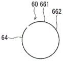
As shown in fig. 7, the check valve 60 includes a main body 64, a supply check valve 65, a recirculation check valve 66, and a hole portion 67.
The main body 64 is formed of, for example, metal into a substantially cylindrical shape. The wall thickness of the main body 64 is set to be relatively small.
The supply check valve 65 is formed by forming a hole connecting the outer wall and the inner wall of the body 64. The supply check valve 65 includes a valve portion 651 and a support portion 652. The valve portion 651 is formed in a substantially circular shape. The support portion 652 is formed to connect the main body 64 and the valve portion 651 and support the valve portion 651. The supply check valve 65 is formed to be elastically deformable in the radial direction.
The recirculation check valve 66 is formed by forming a hole connecting the outer wall with the inner wall of the body 64. The recirculation check valve 66 has a valve portion 661 and a support portion 662. The valve portion 661 is formed in a substantially circular shape. The support portion 662 is formed to connect the main body 64 and the valve portion 661 and support the valve portion 661. The recirculation check valve 66 is formed to be elastically deformable in the radial direction.
The supply check valve 65 and the recirculation check valve 66 are so-called reed valves.
The hole portion 67 is formed in a substantially circular shape between the supply check valve 65 and the recirculation check valve 66 so as to connect the outer wall and the inner wall of the main body 64.
The check valve 60 is provided in the pressure accumulation space 500 such that the supply check valve 65 corresponds to the supply oil passage 54, the recirculation check valve 66 corresponds to the recirculation oil passage 57, and the hole portion 67 corresponds to the 1 st control oil passage 55 (see fig. 6). The check valve 60 is provided on the spool lid portion 52 side with respect to the 2 nd control oil passage 56.
When the hydraulic oil moves from the supply oil passage 54 side to the pressure accumulation space 500 side, the outer peripheral surface of the supply check valve 65 is pressed by the hydraulic oil, whereby the valve portion 651 moves radially inward, and in particular, the support portion 652 deforms and opens the valve, and a gap is formed between the inner wall of the spool 50 and the valve portion 651 of the supply check valve 65. Thereby, the hydraulic oil can flow into the pressure accumulation space 500 through the supply oil passage 54. On the other hand, when the working oil flows from the pressure accumulation space 500 side to the supply oil passage 54 side, the inner peripheral surface of the supply check valve 65 is pressed by the working oil, and the valve portion 651 moves radially outward, and in particular, the support portion 652 deforms to close the valve, and adheres to the inner wall of the spool 50 to block the supply oil passage 54. This restricts the flow of the hydraulic oil from the pressure accumulation space 500 to the outside of the spool 50 through the supply oil passage 54. Thus, the supply check valve 65 allows the hydraulic oil to flow from the supply oil passage 54 side toward the pressure accumulation space 500 side, and restricts the hydraulic oil from flowing from the pressure accumulation space 500 side toward the supply oil passage 54 side.
When the hydraulic oil moves from the recirculation oil passage 57 side to the pressure accumulation space 500 side, the outer peripheral surface of the recirculation check valve 66 is pressed by the hydraulic oil, whereby the valve portion 661 moves radially inward, and particularly the support portion 662 deforms to open the valve, and a gap is formed between the inner wall of the spool 50 and the valve portion 661 of the recirculation check valve 66. Thereby, the working oil can flow into the pressure accumulation space 500 via the recirculation oil passage 57. On the other hand, when the working oil moves from the pressure accumulation space 500 side to the recirculation oil passage 57 side, the inner peripheral surface of the recirculation check valve 66 is pressed by the working oil, and the valve portion 661 moves radially outward, and particularly the support portion 662 deforms to close the valve, and adheres to the inner wall of the spool 50 to block the recirculation oil passage 57. This can restrict the working oil from flowing out of the accumulator space 500 to the outside of the spool 50 through the recirculation oil passage 57. Thus, the recirculation check valve 66 allows the working oil to flow from the recirculation oil passage 57 side toward the pressure accumulation space 500 side, and restricts the working oil from flowing from the pressure accumulation space 500 side toward the recirculation oil passage 57 side.
The configuration of embodiment 3 other than the above is the same as embodiment 1. Therefore, the same configuration as in embodiment 1 can provide the same effects as in embodiment 1.
(embodiment 4)
Fig. 8 shows a part of a valve timing adjusting apparatus according to embodiment 4 of the present disclosure. The sleeve 40, the spool 50, the check valve 60, and the like of embodiment 4 are different from those of embodiment 2.
In the present embodiment, the supply port 43 is formed between the 1 st control port 44 and the 2 nd control port 45.
The spool 50 has a sealing member 58 in place of the spool cover 52. The seal member 58 is formed in a substantially cylindrical shape and is provided inside the spool cylinder portion 51. A substantially cylindrical pressure accumulation space 500 is formed between the outer wall of the seal member 58 and the inner wall of the spool tube 51.
In the present embodiment, the 1 st control oil passage 55, the 2 nd control oil passage 56, and the supply oil passage 54 are integrally formed between the recirculation oil passage 571 and the recirculation oil passage 572.
In the present embodiment, the sleeve 40 forms the drain port 46 radially outward of the spool 50 with respect to the recirculation oil passage 571 between the sleeve cylinder portion 451 and the spool cylinder portion 51. The discharge port 46 communicates with the outside of the valve timing adjustment device 10, i.e., the atmosphere, which is the outside of the camshaft 3, via the variable volume space 401 and the breathing hole 402. The recirculation oil path 571 and the drain port 46 are connected to each other inside the sleeve 40.
The sleeve 40 also has a drain port 49 formed radially outward of the spool 50 with respect to the recirculation oil passage 572 between the sleeve cylinder portion 451 and the spool cylinder portion 51. The drain port 49 communicates with the side opposite to the camshaft 3 with respect to the oil passage switching valve 11, that is, the outside of the valve timing adjusting apparatus 10. The recirculation oil passage 572 and the drain 49 are connected to each other inside the sleeve 40.
The check valve 60 has a supply check valve 61, and recirculation check valves 621 and 622.
The supply check valve 61 and the recirculation check valves 621 and 622 are formed separately. The configuration of the supply check valve 61 and the recirculation check valves 621 and 622 is substantially the same as that of embodiment 2, and therefore, the description thereof is omitted.
The supply check valve 61 is provided between the sleeve 40 and the spool 50 at a position corresponding to the supply port 43. The recirculation check valve 621 is provided between the spool portion 51 and the seal member 58 at a position corresponding to the recirculation oil passage 571. The recirculation check valve 622 is provided between the spool part 51 and the seal member 58 at a position corresponding to the recirculation oil passage 572.
When the working oil moves from the supply port 43 side to the pressure accumulation space 500 side, the supply check valve 61 is deformed radially inward, and a gap is formed between the inner wall of the sleeve 40 and the supply check valve 61. This allows the hydraulic oil to flow into the pressure accumulation space 500 through the supply port 43 and the supply oil passage 54. On the other hand, when the working oil moves from the pressure accumulation space 500 side to the supply port 43 side, the supply check valve 61 is deformed outward in the radial direction, and sticks to the inner wall of the sleeve 40 to close the supply port 43. This restricts the flow of the hydraulic oil from the pressure accumulation space 500 to the outside of the sleeve 40 through the supply oil passage 54 and the supply port 43. Thus, the supply check valve 61 allows the working oil to flow from the supply port 43 side toward the pressure accumulation space 500 side, and restricts the working oil from flowing from the pressure accumulation space 500 side toward the supply port 43 side.
When the working oil flows from the recirculation oil passages 571 and 572 to the pressure accumulation space 500, the recirculation check valves 621 and 622 are deformed radially inward, and gaps are formed between the inner wall of the spool 50 and the recirculation check valves 621 and 622. Thereby, the hydraulic oil can flow into the pressure accumulation space 500 through the recirculation oil passages 571 and 572. On the other hand, when the working oil flows from the pressure accumulation space 500 side to the recirculation oil passages 571 and 572 side, the recirculation check valves 621 and 622 deform outward in the radial direction and adhere to the inner wall of the spool 50 to block the recirculation oil passages 571 and 572. This restricts the working oil from flowing out of the accumulator space 500 to the outside of the spool 50 through the recirculation oil passages 571 and 572. Thus, the recirculation check valves 621 and 622 allow the hydraulic oil to flow from the recirculation oil passages 571 and 572 to the pressure accumulation space 500, and restrict the hydraulic oil from flowing from the pressure accumulation space 500 to the recirculation oil passages 571 and 572.
In the present embodiment, when the spool 50 is positioned in contact with the locking portion 71 (see fig. 8), the working oil is supplied to the advance chamber 202 through the 2 nd control port 45, and the working oil in the retard chamber 201 flows to the drain port 46 through the 1 st control port 44. A part of the working oil flowing into the drain port 46 is returned to the pressure accumulation space 500 via the recirculation oil passage 571 and the recirculation check valve 621. Further, a part of the working oil flowing into the discharge port 46 is discharged to the outside of the camshaft 3, that is, the outside of the valve timing adjustment device 10, that is, the atmosphere, via the variable volume space 401 and the breathing hole 402.
When the spool 50 is positioned in contact with the sleeve bottom portion 452, the working oil is supplied to the retard chamber 201 via the 1 st control port 44, and the working oil in the advance chamber 202 flows to the drain port 49 via the 2 nd control port 45. A part of the working oil flowing into the drain 49 is returned to the pressure accumulation space 500 via the recirculation oil passage 572 and the recirculation check valve 622. Further, a part of the working oil flowing into the discharge port 49 is discharged toward the outside of the valve timing adjusting apparatus 10.
The configuration of embodiment 4 other than the above is the same as embodiment 2. Therefore, the same configuration as in embodiment 2 can provide the same effects as in embodiment 2.
(embodiment 5)
Fig. 9 shows a valve timing adjustment device according to embodiment 5 of the present disclosure. The sleeve 40, the spool 50, the check valve 60, and the like in embodiment 5 are different from those in embodiment 1.
The sleeve 40 includes a sleeve body 451, a sleeve bottom 452, and a screw portion 453, as in embodiment 2.
The supply port 43 is formed to connect the outer wall and the inner wall of the sleeve tube 451. The supply port 43 communicates with the supply hole 101 through a cylindrical gap between the outer wall of the spool 50 and the inner wall of the shaft hole 100.
The 1 st control port 44 is formed on the locking portion 47 side with respect to the supply port 43 so as to connect the outer wall and the inner wall of the sleeve tube 451.
The 2 nd control port 45 is formed on the locking portion 47 side with respect to the 1 st control port 44 so as to connect the outer wall and the inner wall of the sleeve tube 451.
The discharge port 46 is formed between the 1 st control port 44 and the 2 nd control port 45 so as to connect the outer wall and the inner wall of the sleeve tube 451.
In the present embodiment, a pin control port 410 is formed between the supply port 43 and the 1 st control port 44 so as to connect the outer wall and the inner wall of the sleeve tube 451. Further, the vane rotor 30 is provided with a pin control oil passage 305 connecting the pin control port 410 and the housing hole 321. Further, an insertion recess 26 into which the lock pin 81 can be inserted is formed on the blade 32 side of the housing 22. The spring 82 urges the lock pin 81 toward the housing 22 side. The pressure of the hydraulic oil flowing into the pin control port 410 and the pin control oil passage 305 acts in a direction in which the lock pin 81 is pulled out from the fitting recess 26 against the biasing force of the spring 82. When the lock pin 81 is fitted into the fitting recess 26, the relative rotation of the vane rotor 30 with respect to the housing 20 is restricted, and when the lock pin 81 is not fitted into the fitting recess 26, the relative rotation of the vane rotor 30 with respect to the housing 20 is allowed.
A sleeve outer oil passage 33 is formed in the boss 31 of the vane rotor 30. The sleeve-outside oil passage 33 is formed to communicate the discharge port 49 with the outside of the valve timing adjusting apparatus 10.
The spool 50 has a seal member 59 in place of the spool lid portion 52. The seal member 59 is provided inside the spool tube 51. A pressure accumulation space 500 extending in the axial direction of the spool 50 is formed between the inner wall of the seal member 59 and the inner wall of the spool cylindrical portion 51.
The supply oil passage 54, the 1 st control oil passage 55, the recirculation oil passage 57, and the 2 nd control oil passage 56 are formed in a row with a predetermined interval in order from one end side to the other end side of the spool 50. The supply oil passage 54, the 1 st control oil passage 55, the recirculation oil passage 57, and the 2 nd control oil passage 56 communicate the pressure accumulation space 500 with the outside of the spool 50.
In the present embodiment, when the spool 50 is positioned in abutment with the locking portion 71 (see fig. 9), the supply port 43 is not connected to the supply oil passage 54. When the spool 50 moves by a predetermined amount toward the camshaft 3 side, the supply port 43 is connected to the supply oil passage 54, the 1 st control oil passage 55 is connected to the 1 st control port 44, and the 2 nd control port 45 is connected to the recirculation oil passage 57. At this time, the 1 st control oil passage 55 is connected to the pin control port 410.
When the spool 50 is positioned in contact with the sleeve bottom portion 412, the supply port 43 is connected to the supply oil passage 54, the 2 nd control oil passage 56 is connected to the 2 nd control port 45, and the 1 st control port 44 is connected to the recirculation oil passage 57. At this time, the 1 st control oil passage 55 is connected to the pin control port 410.
The drain port 46 is formed in the sleeve 40 so as to be located at least partially radially outward of the spool 50 with respect to the recirculation oil passage 57. More specifically, the drain port 46 is formed in the sleeve 40 such that at least a portion thereof is positioned radially outward of the spool 50 with respect to the recirculation oil passage 57, regardless of whether the spool 50 is positioned in abutment with the locking portion 71 (see fig. 9) or the spool 50 is positioned in abutment with the sleeve bottom portion 452.
Check valve 60 has a supply check valve 68 and a recirculation check valve 69.
The supply check valve 68 and the recirculation check valve 69 are formed separately. The supply check valve 68 and the recirculation check valve 69 are formed by bending a thin metal plate, for example.
The supply check valve 68 is provided at a position corresponding to the supply oil passage 54 in the pressure accumulation space 500. The supply check valve 68 is supported by a supply-side support portion 591 formed on the inner wall of the seal member 59. The supply check valve 68 is elastically deformable in the radial direction of the spool 50.
The recirculation check valve 69 is provided at a position corresponding to the recirculation oil passage 57 in the pressure accumulation space 500. The recirculation check valve 69 is supported by a recirculation side support portion 592 formed on an inner wall of the sealing member 59. The recirculation check valve 69 can be elastically deformed in the radial direction of the spool 50.
When the working oil flows from the supply oil passage 54 side toward the pressure accumulation space 500 side, the supply check valve 68 deforms inward in the radial direction of the spool 50, and a gap is formed between the inner wall of the spool 50 and the supply check valve 68. Thereby, the hydraulic oil can flow into the pressure accumulation space 500 through the supply oil passage 54. On the other hand, when the working oil flows from the pressure accumulation space 500 side to the supply oil passage 54 side, the supply check valve 68 deforms outward in the radial direction of the spool 50, and sticks to the inner wall of the spool 50 to block the supply oil passage 54. This restricts the flow of the hydraulic oil from the pressure accumulation space 500 to the outside of the spool 50 through the supply oil passage 54. Thus, the supply check valve 68 allows the hydraulic oil to flow from the supply oil passage 54 side toward the pressure accumulation space 500 side, and restricts the hydraulic oil from flowing from the pressure accumulation space 500 side toward the supply oil passage 54 side.
When the working oil moves from the recirculation oil passage 57 side to the pressure accumulation space 500 side, the recirculation check valve 69 deforms inward in the radial direction of the spool 50, and a gap is formed between the inner wall of the spool 50 and the recirculation check valve 69. Thereby, the working oil can flow into the pressure accumulation space 500 via the recirculation oil passage 57. On the other hand, when the working oil moves from the pressure accumulation space 500 side to the recirculation oil passage 57 side, the recirculation check valve 69 deforms outward in the radial direction of the spool 50, and sticks to the inner wall of the spool 50 to block the recirculation oil passage 57. This restricts the flow of the working oil from the pressure accumulation space 500 to the outside of the spool 50 via the recirculation oil passage 57. Thus, the recirculation check valve 69 allows the working oil to flow from the recirculation oil passage 57 side toward the pressure accumulation space 500 side, and restricts the working oil from flowing from the pressure accumulation space 500 side toward the recirculation oil passage 57 side.
In the present embodiment, when the spool 50 moves a predetermined amount toward the camshaft 3 from the position of abutment with the locking portion 71 (see fig. 9), the hydraulic oil flows into the pressure accumulation space 500 through the supply port 43, the supply oil passage 54, and the supply check valve 68, and the hydraulic oil flows into the pin control port 410 and the pin control oil passage 305 through the 1 st control oil passage 55, and the relative rotation of the vane rotor 30 with respect to the housing 20 is permitted. At this time, the hydraulic oil in the pressure accumulation space 500 is supplied to the retard chamber 201 via the 1 st control oil passage 55 and the 1 st control port 44, and the hydraulic oil in the advance chamber 202 flows to the recess portion radially outside the recirculation oil passage 57 via the 2 nd control port 45. A part of the working oil flowing into the concave portion is returned to the pressure accumulation space 500 via the recirculation oil passage 57 and the recirculation check valve 69. A part of the hydraulic oil flowing into the recess is discharged to the outside of the valve timing adjusting apparatus 10 through the discharge port 46 and the sleeve outer oil passage 33.
When the spool 50 is in a position abutting against the sleeve bottom 452, the hydraulic oil flows into the pin control port 410 and the pin control oil passage 305 via the 1 st control oil passage 55, and the relative rotation of the vane rotor 30 with respect to the housing 20 is permitted. At this time, the hydraulic oil is supplied to the advance chamber 202 via the 2 nd control oil passage 56 and the 2 nd control port 45, and the hydraulic oil in the retard chamber 201 flows to the recess portion on the outer side in the radial direction of the recirculation oil passage 57 via the 1 st control port 44. A part of the working oil flowing into the concave portion is returned to the pressure accumulation space 500 via the recirculation oil passage 57 and the recirculation check valve 69. A part of the hydraulic oil flowing into the recess is discharged to the outside of the valve timing adjusting apparatus 10 through the discharge port 46 and the sleeve outer oil passage 33.
The configuration of embodiment 5 other than the above is the same as embodiment 1. Therefore, the same configuration as that of embodiment 1 can provide the same effects as those of embodiment 1.
(embodiment 6)
Fig. 10 shows a part of a valve timing adjustment apparatus according to embodiment 6 of the present disclosure. The sleeve 40, the spool 50, the check valve 60, and the like in embodiment 6 are different from those in embodiment 1.
As shown in fig. 10, the sleeve 40 is formed in a three-layer cylindrical shape. The sleeve 40 has a sleeve bottom 452 and a threaded portion 453, as in embodiment 2, and the sleeve body 451.
The supply port 43 is formed to connect the outer wall and the inner wall of the sleeve tube 451. The oil pump 8 is connected to the supply port 43.
The 1 st control port 44 is formed on the locking portion 47 side with respect to the supply port 43 so as to connect the outer wall and the inner wall of the sleeve tube 451.
The 2 nd control port 45 is formed on the locking portion 47 side with respect to the 1 st control port 44 so as to connect the outer wall and the inner wall of the sleeve tube 451.
A discharge port 454 is formed at the center of the sleeve bottom 452. That is, the discharge port 454 is formed at the camshaft 3-side end of the sleeve 40 on the shaft of the sleeve 40. The discharge port 454 is formed to connect the volume-variable space 401 with the outside of the camshaft 3, that is, the outside of the valve timing adjustment apparatus 10.
In the present embodiment, the intermediate oil passage 455 is formed in the thickness of the sleeve cylindrical portion 451. The intermediate oil passage 455 is formed to extend in the axial direction of the sleeve 40 and communicate with the volume-variable space 401. The 1 st control port 44 and the 2 nd control port 45 communicate with the intermediate oil passage 455.
In the present embodiment, the spool lid portion 52 is formed integrally with the spool tube portion 51. The spool bottom 53 is formed separately from the spool tube 51 and is press-fitted into the spool tube 51 on the side opposite to the spool lid 52.
The recirculation oil passage 57 is formed near the spool lid portion 52 of the spool cylinder portion 51 so as to connect the outer wall and the inner wall of the spool cylinder portion 51. The recirculation oil passage 57 is formed to extend in the radial direction of the spool 50. The recirculation oil passage 57 is connected to the drain 454 via the volume variable space 401. That is, the recirculation oil passage 57 and the drain port 454 are connected to each other in the volume-variable space 401 inside the sleeve 40.
The supply oil passage 54 is formed on the spool bottom 53 side with respect to the recirculation oil passage 57 so as to connect the outer wall and the inner wall of the spool cylinder 51.
The 1 st control oil passage 55 and the 2 nd control oil passage 56 are integrally formed on the spool bottom portion 53 side of the supply oil passage 54 so as to connect the outer wall and the inner wall of the spool tubular portion 51.
The check valve 60 has a supply check valve 61 and a recirculation check valve 62.
The supply check valve 61 is provided in the pressure accumulation space 500 so as to correspond to the supply oil passage 54. The recirculation check valve 62 is provided in the pressure accumulation space 500 so as to correspond to the recirculation oil passage 57.
In the present embodiment, when the spool 50 is positioned in contact with the locking portion 71 (see fig. 10), the hydraulic oil is supplied to the advance chamber 202 via the 2 nd control port 45, and the hydraulic oil in the retard chamber 201 flows to the intermediate oil passage 455 via the 1 st control port 44. A part of the hydraulic oil flowing into the intermediate oil passage 455 is returned to the pressure accumulation space 500 via the variable-volume space 401, the recirculation oil passage 57, and the recirculation check valve 62. A part of the hydraulic oil flowing into the intermediate oil passage 455 is discharged to the outside of the valve timing adjusting apparatus 10 through the variable volume space 401 and the discharge port 454.
When the spool 50 is positioned in contact with the sleeve bottom portion 452, the hydraulic oil is supplied to the retard chamber 201 via the 1 st control port 44, and the hydraulic oil in the advance chamber 202 flows to the intermediate oil passage 455 via the 2 nd control port 45. A part of the hydraulic oil flowing into the intermediate oil passage 455 is returned to the pressure accumulation space 500 via the recirculation oil passage 57 and the recirculation check valve 62. A part of the hydraulic oil flowing into the intermediate oil passage 455 is discharged to the outside of the valve timing adjusting apparatus 10 through the variable volume space 401 and the discharge port 454.
The configuration of embodiment 6 other than the above is the same as embodiment 1. Therefore, the same configuration as that of embodiment 1 can provide the same effects as those of embodiment 1.
As described above, in the present embodiment, the discharge port 454 is formed in the end portion of the sleeve 40 on the camshaft 3 side on the shaft of the sleeve 40. The recirculation oil passage 57 is formed to extend in the radial direction of the spool 50. Therefore, the hydraulic oil from each hydraulic chamber can be discharged toward the camshaft 3.
(7 th embodiment)
Fig. 11 shows a part of a valve timing adjustment apparatus according to embodiment 7 of the present disclosure. The configuration of the spool 50 and the check valve 60 according to embodiment 6 are different from those according to embodiment 6.
In the present embodiment, the recirculation oil passage 57 is formed in the center of the spool lid portion 52. That is, the recirculation oil passage 57 is formed in the camshaft 3-side end portion of the spool 50 on the shaft of the spool 50.
Check valve 60 has a recirculation check valve 73 in place of recirculation check valve 62. The recirculation check valve 73 is formed in a spherical shape, for example, from metal, and is provided in a position corresponding to the recirculation oil passage 57 in the pressure accumulation space 500.
The storage portion 74 is provided at the end of the pressure accumulation space 500 on the spool lid portion 52 side. The housing 74 is formed in a bottomed tubular shape, and is fitted into the spool tubular portion 51 so as to house the recirculation check valve 73 therein. The housing 74 has a hole 741 penetrating the center of the bottom. Thereby, the inside and the outside of the housing 74 communicate with each other through the hole 741.
The recirculation check valve 73 is movable inside the housing 74.
When the hydraulic oil moves from the recirculation oil passage 57 side to the pressure accumulation space 500 side, the recirculation check valve 73 moves to the bottom side of the housing 74 and separates from the recirculation oil passage 57 and the spool lid portion 52. Accordingly, the hydraulic oil can flow into the pressure accumulation space 500 through the recirculation oil passage 57 and can move toward the supply check valve 61 with respect to the housing 74 through the hole 741. On the other hand, when the hydraulic oil flows from the pressure accumulation space 500 side to the recirculation oil passage 57 side, the recirculation check valve 73 abuts against the spool lid portion 52 to block the recirculation oil passage 57. This restricts the flow of the working oil from the pressure accumulation space 500 to the outside of the spool 50 via the recirculation oil passage 57. Thus, the recirculation check valve 73 allows the working oil to flow from the recirculation oil passage 57 side toward the pressure accumulation space 500 side, and restricts the working oil from flowing from the pressure accumulation space 500 side toward the recirculation oil passage 57 side.
In the present embodiment, when the spool 50 is positioned in contact with the locking portion 71 (see fig. 11), the hydraulic oil is supplied to the advance chamber 202 via the 2 nd control port 45, and the hydraulic oil in the retard chamber 201 flows to the intermediate oil passage 455 via the 1 st control port 44. A part of the hydraulic oil flowing into the intermediate oil passage 455 is returned to the pressure accumulation space 500 via the variable-volume space 401, the recirculation oil passage 57, and the recirculation check valve 73. A part of the hydraulic oil flowing into the intermediate oil passage 455 is discharged to the outside of the valve timing adjusting apparatus 10 through the variable volume space 401 and the discharge port 454.
When the spool 50 is positioned in contact with the sleeve bottom portion 452, the hydraulic oil is supplied to the retard chamber 201 via the 1 st control port 44, and the hydraulic oil in the advance chamber 202 flows to the intermediate oil passage 455 via the 2 nd control port 45. A part of the hydraulic oil flowing into the intermediate oil passage 455 is returned to the pressure accumulation space 500 via the recirculation oil passage 57 and the recirculation check valve 73. A part of the hydraulic oil flowing into the intermediate oil passage 455 is discharged to the outside of the valve timing adjusting apparatus 10 through the variable volume space 401 and the discharge port 454.
The configuration of embodiment 7 other than the above is the same as embodiment 6. Therefore, the same structure as that of embodiment 6 can provide the same effects as those of embodiment 6.
As described above, in the present embodiment, the discharge port 454 is formed in the end portion of the sleeve 40 on the camshaft 3 side on the shaft of the sleeve 40. The recirculation oil passage 57 is formed in the shaft of the spool 50 at the end of the spool 50 on the camshaft 3 side. Therefore, as in embodiment 6, the hydraulic oil from each hydraulic chamber can be discharged toward the camshaft 3.
(other embodiments)
In the above-described embodiment, the sleeve 40 and the spool 50 constituting the oil passage switching valve 11 are disposed in the center portion of the vane rotor 30. In contrast, in another embodiment of the present disclosure, the oil passage switching valve 11 may be disposed at a position other than the central portion of the vane rotor 30, for example, outside the casing 20.
In addition, in embodiment 1 and the like described above, an example is shown in which at least a part of the drain port is located radially outward of the spool 50 with respect to the recirculation oil passage regardless of the position of the spool 50 with respect to the sleeve 40. In contrast, in another embodiment of the present disclosure, the drain port may not be located radially outward of the spool 50 with respect to the recirculation oil passage, as long as the drain port can communicate with the inner recirculation oil passage of the sleeve 40.
In another embodiment of the present disclosure, the housing 20 may be coupled to the crankshaft 2 by a transmission member such as a belt instead of the chain 6.
In the above-described embodiment, the crankshaft 2 is set as the "1 st shaft" and the camshaft 3 is set as the "2 nd shaft". In contrast, in another embodiment of the present disclosure, the crankshaft 2 may be referred to as the "2 nd shaft" and the camshaft 3 may be referred to as the "1 st shaft". That is, the vane rotor 30 may be fixed to an end portion of the crankshaft 2, and the housing 20 may rotate in conjunction with the camshaft 3.
The valve timing adjusting apparatus 10 of the present disclosure may also adjust the valve timing of the exhaust valve 5 of the engine 1.
As described above, the present disclosure is not limited to the above embodiments, and can be implemented in various ways without departing from the scope of the present disclosure.
The present disclosure is explained based on the embodiments. However, the present disclosure is not limited to the embodiment and the structure. The present disclosure also includes various modifications and equivalent variations within the scope and range. In addition, various combinations and modes, even other combinations and modes including only one of the elements above or below it, are also within the scope and spirit of the present disclosure.