Disclosure of Invention
The embodiment of the application provides a mobile terminal to solve the problem that the setting of a front camera is not favorable for improving the screen occupation ratio of the mobile terminal.
A mobile terminal, comprising:
the first rear shell comprises a first surface and a second surface which are arranged oppositely;
the display screen, set up in one side at first surface place:
the second rear shell is arranged on one side where the second surface is located, and is connected with the first rear shell in a sliding mode; and
the camera module is arranged on the second rear shell and provided with a light incident surface facing the display screen; the second rear shell can slide relative to the first rear shell along a set direction and is provided with a first position and a second position; the camera module is shielded by the display screen in the first position, and the light incident surface is exposed from one side of the display screen in the second position; the included angle between the set direction and the length direction of the mobile terminal is an acute angle.
In one embodiment, the camera module comprises a front camera and a mounting seat, and the mounting seat is respectively connected with the front camera and the second rear shell; the mobile terminal also comprises a telephone receiver arranged on the second rear shell; the telephone receiver is shielded by the display screen in the first position, the telephone receiver is exposed from one side where the display screen is located in the second position, the length direction of the telephone receiver is parallel to the width direction of the display screen, and the length direction of the mounting seat is parallel to the length direction of the display screen.
In one embodiment, the set direction is parallel to an extending direction of a diagonal line of the first rear case.
In one embodiment, the first rear housing further comprises a side peripheral surface connected between the first surface and the second surface, the side peripheral surface being located at the periphery of the second surface; the second rear shell comprises an outer surface, an inner surface and an outer peripheral surface, wherein the outer surface and the inner surface are arranged in a reverse manner, the outer peripheral surface is connected between the inner surface and the outer surface, the outer peripheral surface is positioned on the periphery of the outer surface, and the inner surface faces to one side where the display screen is positioned; in the first position, the side peripheral surface is aligned with the outer peripheral surface.
In one embodiment, the side peripheral surfaces comprise a first side peripheral surface and a second side peripheral surface which are arranged oppositely, and a third side peripheral surface and a fourth side peripheral surface which are arranged oppositely; the third side surface is connected to one end of the first side surface and the second side surface, and the fourth side surface is connected to the other end of the first side surface and the second side surface; the first lateral surface and the second lateral surface are respectively positioned at two sides of the width direction of the mobile terminal, and the third lateral surface and the fourth lateral surface are respectively positioned at two sides of the length direction of the mobile terminal; the peripheral surfaces comprise a first peripheral surface and a second peripheral surface which are arranged in a back-to-back manner, and a third peripheral surface and a fourth peripheral surface which are arranged in a back-to-back manner, the third peripheral surface is connected with one end of the first peripheral surface and one end of the second peripheral surface, and the fourth peripheral surface is connected with the other end of the first peripheral surface and the other end of the second peripheral surface; in the first position, the first peripheral surface is flush with the first side surface, the second peripheral surface is flush with the second side surface, the third peripheral surface is flush with the third side surface, and the fourth peripheral surface is flush with the fourth side surface; in the second position, the first peripheral surface is offset from the first lateral surface, the second peripheral surface is offset from the second lateral surface, the third peripheral surface is offset from the third lateral surface, and the fourth peripheral surface is offset from the fourth lateral surface.
In one embodiment, the first side surface is in smooth transition with the third side surface and the fourth side surface, respectively, and the second side surface is in smooth transition with the third side surface and the fourth side surface, respectively.
In one embodiment, the outer surface is in smooth transition with the first, second, third and fourth outer peripheral surfaces, respectively; and/or the first peripheral surface is in smooth transition with the third peripheral surface and the fourth peripheral surface respectively, and the second peripheral surface is in smooth transition with the third peripheral surface and the fourth peripheral surface respectively.
In one embodiment, the second surface protrudes outwards to a side away from the display screen to form a boss, and the boss extends along the set direction; the inner surface is sunken to one side where the outer surface is located to form an accommodating groove, and the boss is accommodated in the accommodating groove at the first position.
In one embodiment, in the setting direction, a plurality of stopping grooves are formed on the groove wall of the accommodating groove; the mobile terminal further comprises a clamping component, and the clamping component comprises a first elastic piece and a thimble; the second surface is provided with a mounting groove, the mounting groove comprises a first groove and a second groove which are mutually communicated, the first groove and the second groove both extend along a direction perpendicular to the set direction, the maximum width of the first groove is larger than that of the second groove, and the first elastic piece is arranged in the first groove; the thimble comprises a main body part and a flange, wherein the main body part and the flange are integrally formed; the main body part abuts against the second rear shell, and the flange abuts against the first elastic piece; the flange is accommodated in the first groove, and the main body part is accommodated in the second groove; when the second rear shell moves between the first position and the second position, the thimble can slide and stretch along the direction perpendicular to the set direction to slide into the clamping groove or slide out of the clamping groove, and the flange can abut against the groove wall of the first groove to limit the moving range of the main body part.
In one embodiment, the mobile terminal further comprises a secondary ejection mechanism, the secondary ejection mechanism comprises a second elastic member, a movable block and a pull rod, the second elastic member is respectively connected with the movable block and the first rear shell, one end of the pull rod is rotatably connected with the first rear shell, the other end of the pull rod is slidably connected with the movable block, and the movable block is fixedly connected with the second rear shell; the second rear shell is pushed along the set direction, and the pull rod can be buckled with the movable block so that the second rear shell and the first rear shell are clamped at a first position; when the second rear shell is clamped with the first rear shell, the second rear shell is pushed along the set direction, the pull rod can be separated from the movable block, and the second elastic piece can push the second rear shell to a second position.
In one embodiment, a sliding groove is formed in the movable block, the sliding groove comprises an entry groove, a clamping groove and an exit groove, the clamping groove is respectively communicated with the entry groove and the exit groove, and the exit groove is communicated with the entry groove; the bottom wall of the inlet groove is provided with a plurality of steps so that the depth of the inlet groove is increased from the inlet end of the inlet groove to the position of the clamping groove; the depth of the withdrawing groove is smaller than that of the clamping groove, and the bottom wall of the withdrawing groove and the bottom wall of the clamping groove are in smooth transition; the second rear shell is pushed along the set direction, the free end of the pull rod slides into the entering groove from the entrance end of the entering groove and slides along the extending direction of the entering groove to slide into the clamping groove, and the pull rod is clamped with the movable block in the clamping groove so that the second rear shell and the first rear shell are clamped at a first position; when the second rear shell is clamped with the first rear shell, the second rear shell is pushed along the set direction, the pull rod slides into the withdrawing groove and slides along the extending direction of the withdrawing groove to slide into the groove, and the elastic piece pushes the second rear shell to a second position.
In one embodiment, the camera module comprises a camera, a distance sensor and an ambient light sensor, and the camera, the distance sensor and the ambient light sensor are respectively in communication connection with a microprocessor of the mobile terminal.
In one embodiment, the camera module further comprises an infrared lens, a floodlight sensing element and a dot matrix projector, and the infrared lens, the floodlight sensing element and the dot matrix projector are respectively in communication connection with the microprocessor.
Above-mentioned mobile terminal, the second backshell can slide along setting for the direction relatively first backshell, the module of making a video recording is sheltered from by the display screen when the first position, goes into the plain noodles and exposes from one side at display screen place when the second position, has realized hiding and exposing of the module of making a video recording through the slip of second backshell on first backshell, has avoided the module of making a video recording to occupy the area of one side at mobile terminal's display screen place, consequently can realize mobile terminal's high screen and account for the ratio. Because the included angle between the set direction and the length direction of the mobile terminal is an acute angle, the second rear shell slides obliquely on the first rear shell, so that force is applied to the second rear shell by a user, and the second rear shell is pushed to slide on the first rear shell.
Detailed Description
To facilitate an understanding of the present application, the present application will now be described more fully with reference to the accompanying drawings. Preferred embodiments of the present application are illustrated in the accompanying drawings. This application may, however, be embodied in many different forms and should not be construed as limited to the embodiments set forth herein. Rather, these embodiments are provided so that this disclosure will be thorough and complete.
It will be understood that when an element is referred to as being "secured to" another element, it can be directly on the other element or intervening elements may also be present. When an element is referred to as being "connected" to another element, it can be directly connected to the other element or intervening elements may also be present. The terms "vertical," "horizontal," "left," "right," and the like as used herein are for illustrative purposes only.
Unless defined otherwise, all technical and scientific terms used herein have the same meaning as commonly understood by one of ordinary skill in the art to which this application belongs. The terminology used herein in the description of the present application is for the purpose of describing particular embodiments only and is not intended to be limiting of the application. As used herein, the term "and/or" includes any and all combinations of one or more of the associated listed items.
As used herein, a "communication terminal" (or simply "terminal") includes, but is not limited to, a device that is configured to receive/transmit communication signals via a wireline connection, such as via a Public Switched Telephone Network (PSTN), a Digital Subscriber Line (DSL), a digital cable, a direct cable connection, and/or another data connection/network, and/or via a wireless interface (e.g., for a cellular network, a Wireless Local Area Network (WLAN), a digital television network such as a DVB-H network, a satellite network, an AM-FM broadcast transmitter, and/or another communication terminal). A communication terminal arranged to communicate over a wireless interface may be referred to as a "wireless communication terminal", "wireless terminal" or "mobile terminal". Examples of mobile terminals include, but are not limited to, satellite or cellular telephones; a Personal Communications System (PCS) terminal that may combine a cellular radiotelephone with data processing, facsimile and data communications capabilities; PDAs that may include radiotelephones, pagers, internet/intranet access, Web browsers, notepads, calendars, and/or Global Positioning System (GPS) receivers; and conventional laptop and/or palmtop receivers or other electronic devices that include a radiotelephone transceiver.
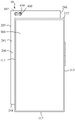
Referring to fig. 1 and 2, in one embodiment, the mobile terminal 10 is a handset. The mobile terminal 10 includes a first rear case 100, a second rear case 200, a display screen 300, and a camera module 400. The first rear case 100 includes a first surface (not shown) and a second surface 110 that are opposite to each other. The display screen 300 is disposed at a side where the first surface is located. The second rear case 200 is disposed at a side where the second surface 110 is located, and the second rear case 200 is slidably connected to the first rear case 100. The camera module 400 is disposed on the second rear case 200, and the camera module 400 has a light incident surface 410 facing the display screen 300. The second rear case 200 is slidable in a set direction with respect to the first rear case 100 and has a first position and a second position. The camera module 400 is shielded by the display screen 300 in the first position, and the light incident surface 410 is exposed from the side of the display screen 300 in the second position. Wherein, the angle between the set direction and the length direction of the mobile terminal 10 is an acute angle. In one embodiment, the first rear housing 100 has a substantially rectangular block shape, the second rear housing 200 has a substantially rectangular block shape, and the second rear housing 200 is slidably disposed on a side of the first rear housing 100 facing away from the display screen 300. The second rear case 200 is slidable on the first rear case 100 along a set direction, which is at an acute angle with respect to the length direction of the mobile terminal 10, and it is understood that the set direction may also be regarded as an acute angle with respect to the width direction of the mobile terminal 10.
Specifically, referring to fig. 3 and 4, in one embodiment, the mobile terminal 10 is generally rectangular in block shape when the second rear housing 200 is in the first position. The first rear case 100 further includes a side circumferential surface connected between the first surface and the second surface 110, the side circumferential surface being located at the outer circumference of the second surface 110. Specifically, the side circumferential surfaces include a first side circumferential surface 111 and a second side circumferential surface 113 which are oppositely arranged, and a third side circumferential surface 115 and a fourth side circumferential surface 117 which are oppositely arranged, the third side circumferential surface 115 is connected to one end of the first side circumferential surface 111 and the second side circumferential surface 113, and the fourth side circumferential surface 117 is connected to the other end of the first side circumferential surface 111 and the second side circumferential surface 113. In the embodiment in which the mobile terminal 10 has a rectangular block shape, the first side peripheral surface 111 and the second side peripheral surface 113 are respectively connected to two long sides of the rectangle, and the third side peripheral surface 115 and the fourth side peripheral surface 117 are respectively connected to two short sides of the rectangle, that is, the first side peripheral surface 111 and the second side peripheral surface 113 are respectively located at two sides of the width direction of the mobile terminal 10, and the third side peripheral surface 115 and the fourth side peripheral surface 117 are respectively located at two sides of the length direction of the mobile terminal 10. Further, in the embodiment where the mobile terminal 10 has a rectangular block shape, the third peripheral surface 115 is located at the top of the mobile terminal 10, and the fourth peripheral surface 117 is located at the bottom of the mobile terminal 10. A sound hole and a connector can be formed on the fourth peripheral surface 117, the sound hole can be used for transmitting sound of a speaker, and the connector can be used for correspondingly arranging an earphone seat or a USB seat and the like.
Above-mentioned mobile terminal 10, second backshell 200 can slide along setting for the direction relative first backshell 100, the module 400 of making a video recording is sheltered from by display screen 300 when the first position, go into plain noodles 410 and expose from the one side at display screen 300 place when the second position, the slip through second backshell 200 on first backshell 100 has realized hiding and exposing of the module 400 of making a video recording, the area of the one side at the display screen 300 place that the module 400 of making a video recording occupy mobile terminal 10 has been avoided, consequently, mobile terminal 10's high screen ratio of occupying can be realized. Since the included angle between the set direction and the length direction of the mobile terminal 10 is an acute angle, the second rear housing 200 slides obliquely on the first rear housing 100, which is beneficial for the user to apply force to the second rear housing 200 to push the second rear housing 200 to slide on the first rear housing 100. For example, the user can push the second rear case 200 from the first position to the second position by holding the first rear case 100 with one hand and pushing the second rear case 200 in the set direction with the other hand. Likewise, the user can also conveniently push the second rear case 200 back to the first position in the set direction.
In one embodiment, the angle between the predetermined direction and the longitudinal direction of the mobile terminal 10 is 10 to 80 degrees. Further, in an embodiment, the set direction of the second rear housing 200 sliding along the first rear housing 100 forms an angle of 30 to 60 degrees with the length direction of the mobile terminal 10. When the setting direction is within the above range, the second rear case 200 moves a short distance on the first rear case 100 along the setting direction to expose a relatively large area, thereby facilitating the setting of the camera module 400 and the sliding mechanism, allowing the sliding mechanism of the second rear case 200 to be easily set, and allowing the sliding distance to be easily controlled.
In an embodiment, the set direction of the sliding of the second rear case 200 on the first rear case 100 is parallel to the extension direction of the diagonal line of the first rear case 100. On one hand, the above structure allows the sliding direction of the second rear case 200 to be easily controlled due to the long length of the diagonal line of the first rear case 100, and facilitates the smooth sliding of the second rear case 200 at the first rear case 100 due to the long contact length that can be set between the second rear case 200 and the first rear case 100. On the other hand, when the second rear case 200 moves to the second position along the diagonal direction of the first rear case 100, a part of the area of the second rear case 200 can be exposed on both the length direction side and the width direction side of the mobile terminal 10, and the exposed part can be used for adding an auxiliary function, for example, a sub display screen or a receiver or a sound outlet or a fingerprint module can be arranged on the exposed part, or a decorative pattern can be arranged on the exposed part to beautify the appearance of the mobile terminal 10.
It is understood that the camera module 400 may include a camera, a distance sensor and an ambient light sensor, which are respectively in communication with the microprocessor of the mobile terminal 10. Specifically, in one embodiment, the camera can be used to provide video call, self-timer, and other functions. The distance sensor may be used to detect the distance between the display screen 300 and the user's face to enable the display screen 300 to be lit or extinguished while the user is receiving a call. The ambient light sensor may be used to detect the brightness of the ambient light, so that the display screen 300 can adjust the display brightness according to the brightness of the ambient light, so that the user can comfortably view the information on the display screen 300. In an embodiment, the camera module 400 may further include an infrared lens, a floodlight sensing element and an array projector, and the infrared lens, the floodlight sensing element and the array projector are respectively in communication connection with the microprocessor. The infrared lens, the dot matrix projector and the floodlight sensing element may be used in the face recognition process of the mobile terminal 10. One or more of these electronic components may be mounted on the second rear case 200. In an embodiment, the second rear case 200 may further be provided with electronic components such as a rear camera and a flash lamp, which are not described herein again.
In an embodiment, the first side circumferential surface 111 of the first rear shell 100 smoothly transitions with the third side circumferential surface 115 and the fourth side circumferential surface 117, respectively, and the second side circumferential surface 113 smoothly transitions with the third side circumferential surface 115 and the fourth side circumferential surface 117, respectively. Specifically, the connection portion of the first side circumferential surface 111 and the third side circumferential surface 115 may adopt a curved surface, such as a cambered transition, so that the first side circumferential surface 111 and the third side circumferential surface 115 are smoothly transited. The connecting portion of the first peripheral surface 111 and the fourth peripheral surface 117 may adopt a curved surface, such as a cambered surface transition, so as to make the first peripheral surface 111 and the fourth peripheral surface 117 smoothly transition. In an embodiment, the connecting portion between the second peripheral surface 113 and the third peripheral surface 115 or the fourth peripheral surface 117 may also adopt a curved surface, such as an arc surface transition, so as to make the second peripheral surface 113 smoothly transition with the third peripheral surface 115 or the fourth peripheral surface 117. With the above structure, the appearance of the mobile terminal 10 can be made more beautiful.
Referring also to fig. 5, in an embodiment, the second rear case 200 includes an inner surface 241, an outer surface 243 which are opposite to each other, and an outer circumferential surface connected between the inner surface 241 and the outer surface 243, and the outer circumferential surface is located at the periphery of the outer surface 243. In the first position, the side circumferential surface of the first rear case 100 can be aligned with the outer circumferential surface of the second rear case 200 to provide the mobile terminal 10 with better appearance integrity. Specifically, the outer peripheral surfaces include a first outer peripheral surface 245 and a second outer peripheral surface 246 which are arranged oppositely, and a third outer peripheral surface 247 and a fourth outer peripheral surface 248 which are arranged oppositely, wherein the third outer peripheral surface 247 is connected with one ends of the first outer peripheral surface 245 and the second outer peripheral surface 246, and the fourth outer peripheral surface 248 is connected with the other ends of the first outer peripheral surface 245 and the second outer peripheral surface 246. The inner surface 241 faces the display screen 300. Specifically, in the embodiment in which the second rear case 200 has a rectangular block shape, the first outer circumferential surface 245 and the second outer circumferential surface 246 are respectively located on both sides in the width direction of the second rear case 200, and the third outer circumferential surface 247 and the fourth outer circumferential surface 248 are respectively located on both sides in the length direction of the second rear case 200. In the first position, the first peripheral surface 245 is flush with the first side surface 111, the second peripheral surface 246 is flush with the second side surface 113, the third peripheral surface 247 is flush with the third side surface 115, and the fourth peripheral surface 248 is flush with the fourth side surface 117. When the second rear case 200 slides on the first rear case 100 to the second position along the setting direction, the first outer circumferential surface 245 is misaligned with the first side circumferential surface 111, the second outer circumferential surface 246 is misaligned with the second side circumferential surface 113, the third outer circumferential surface 247 is misaligned with the third side circumferential surface 115, and the fourth outer circumferential surface 248 is misaligned with the fourth side circumferential surface 117.
In one embodiment, outer surface 243 smoothly transitions with first outer circumferential surface 245, second outer circumferential surface 246, third outer circumferential surface 247, and fourth outer circumferential surface 248, respectively. For example, the connection portion between the outer surface 243 and the first outer circumferential surface 245 may be a curved surface, such as a smooth arc transition, and the connection portion between the outer surface 243 and the second outer circumferential surface 246, the third outer circumferential surface 247, or the fourth outer circumferential surface 248 may be a curved surface, such as a smooth arc transition. In one embodiment, first peripheral surface 245 smoothly transitions with third peripheral surface 247 or fourth peripheral surface 248, and second peripheral surface 246 smoothly transitions with third peripheral surface 247 and fourth peripheral surface 248. With the above structure, the second rear case 200 may not have a sharp protruding portion, so that the mobile terminal 10 may have an aesthetic appearance.
Referring to fig. 6, in an embodiment, the second surface 110 protrudes outward away from the display screen 300 to form a boss 116, and the boss 116 extends along a predetermined direction. The inner surface 241 is recessed toward the outer surface 243 to form a receiving groove 250, and the boss 116 is received in the receiving groove 250 at the first position. The second rear case 200 may be covered on the boss 116 by the receiving groove 250 and allow the second rear case 200 to slide in a set direction along the extending direction of the boss 116. The above structure is advantageous for assembling the second rear case with the first rear case 100, and is advantageous for simplifying the sliding structure of the second rear case 200 with the first rear case 100, so as to facilitate the sliding of the second rear case 200 on the first rear case 100.
Referring to fig. 7 and 8, in an embodiment, a plurality of catching grooves 260 are formed on a groove wall of the receiving groove 250 in a sliding direction of the second rear case 200, i.e., in a set direction. The mobile terminal 10 may further include a card ton assembly 500, wherein the card ton assembly 500 includes a first elastic member 510 and a thimble 520, and the first elastic member 510 is connected to the first rear housing 100 and the thimble 520, respectively. When the second rear case 200 moves between the first position and the second position, the thimble 520 can slide and extend in a direction perpendicular to the set direction to slide into or out of the catching groove 260. The arrangement of the chucking groove 260 and the chucking assembly 500 enables a user to feel a distinct pause feeling when pushing the second rear case 200 to slide, thereby giving the user a definite feedback to enhance the user's experience.
Specifically, referring to fig. 8 and 9, in one embodiment, the first elastic element 510 is a spring, and the thimble 520 is substantially cylindrical. The second surface 110 of the first rear housing 100 is provided with a mounting groove 600, the first elastic element 510 and the thimble 520 can be accommodated in the mounting groove 600, a baffle (not shown) can be disposed on a side of the mounting groove 600 facing away from the first surface, and the baffle is covered on the mounting groove 600. The blocking plate may be coupled to the first rear case 100 using a screw fastener, so that the blocking plate is fixedly coupled to the first rear case 100, and the first elastic member 510 and the thimble 520 are securely positioned on the first rear case 100. One end of the thimble 520 abuts against the first elastic element 510, and the other end of the thimble 520 is exposed out of the mounting groove 600 and protrudes out of the edge of the boss 116. When the second rear housing 200 slides along the set direction, the thimble 520 may compress the first elastic member 510, so that the first elastic member 510 generates an elastic force, and the thimble 520 slides and expands in a direction perpendicular to the set direction. The protruding portion of the thimble 520 can slide into the click groove 260 or slide out of the click groove 260, thereby generating a distinct click feeling.
Further, referring to fig. 8 and 9, in an embodiment, the thimble 520 includes a main body portion 521 and a flange 523, and the main body portion 521 and the flange 523 are integrally formed. The main body 521 has a substantially cylindrical shape, one end of the main body 521 is connected to the flange 523, and the other end of the main body 521 abuts against the second rear case 200. The flange 523 has a substantially cylindrical shape, one end of the flange 523 is connected to the main body 521, the other end of the flange 523 abuts against the first elastic member 510, and the maximum width of the flange 523 is greater than the maximum width of the main body 521. In one embodiment, the mounting groove 600 includes a first groove 610 and a second groove 620, the first groove 610 and the second groove 620 are communicated, and both the first groove 610 and the second groove 620 extend in a direction perpendicular to the set direction, and the maximum width of the first groove 610 is greater than the maximum width of the second groove 620. The first elastic member 510 is disposed in the first groove 610 and abuts against the first rear case 100. The flange 523 is received in the first slot 610 and the body 521 is received in the second slot 620. After the thimble 520 is mounted in the mounting groove 600, the flange 523 can abut against a wall of the first groove 610. The above structure can limit the moving range of the main body 521, and prevent the main body 521 from being removed from the mounting groove 600 under the elastic force of the first elastic member 510. It is understood that needle 520 may have other configurations. For example, thimble 520 may be prismatic. It is understood that the first elastic member 510 may also be a spring, a plastic, a silicone, a rubber, etc.
Referring to fig. 10 and 11, in an embodiment, the mobile terminal 10 may further include a secondary pop-up mechanism 700, where the secondary pop-up mechanism 700 includes a second elastic member 710, a movable block 720 and a pull rod 730, and the second elastic member 710 is connected with the movable block 720 and the first rear case 100, respectively. Specifically, in an embodiment, the second elastic member 710 is a spring, one end of the second elastic member 710 is fixedly connected to the first rear case 100, and the other end of the second elastic member 710 is fixedly connected to the movable block 720. One end of the pull rod 730 is rotatably connected to the first rear case 100, and the other end of the pull rod 730 is slidably connected to the movable block 720. It is understood that the end of the pull rod 730 slidably connected to the movable block 720 may be regarded as a free end of the pull rod 730. In one embodiment, the free end of the pull rod 730 is in the shape of a right angle hook. The movable block 720 is fixedly connected with the second rear case 200. The fixed connection may be implemented in various manners, for example, the movable block 720 may be fixedly connected to the second rear case 200 by a screw connection, welding, adhesion, or the like. In an embodiment, when the second rear housing 200 is located at the second position, the second rear housing 200 is pushed along the set direction, the pull rod 730 can be buckled with the movable block 720, so that the second rear housing 200 is buckled with the first rear housing 100, the second rear housing 200 returns to the first position, and the second elastic element 710 is compressed, as shown in fig. 10. Referring to fig. 12 and 13, after the second rear case 200 is engaged with the first rear case 100, the second rear case 200 is pushed in the set direction, the pull rod 730 can be disengaged from the movable block 720, and the second elastic member 710 releases the elastic potential energy to push the second rear case 200 to the second position, as shown in fig. 12.
Specifically, referring to fig. 11, in an embodiment, the movable block 720 is provided with a sliding groove 740, the sliding groove 740 includes an entry groove 741, an engagement groove 743 and an exit groove 745, the engagement groove 743 is respectively communicated with the entry groove 741 and the exit groove 745 is communicated with the entry groove 741. The bottom wall of the entry groove 741 is provided with a plurality of steps (not shown) so that the depth of the entry groove 741 increases from the entrance end of the entry groove 741 to the position of the engagement groove 743. The step is provided to enable the free end of the pulling rod 730 to move in one direction, for example, the step is provided to prevent the free end of the pulling rod 730 from sliding into the groove 741 from the engaging groove 743. The depth of the escape groove 745 is smaller than the depth of the engaging groove 743, and the bottom wall of the escape groove 745 and the bottom wall of the engaging groove 743 smoothly transition, so that the free end of the pull rod 730 can slide into the escape groove 745 from the engaging groove 743.
In an embodiment, when the second rear housing 200 is located at the second position, the second rear housing 200 is pushed in the set direction, the free end of the pull rod 730 slides into the entrance groove 741 from the entrance end of the entrance groove 741, and slides in one direction along the extending direction of the entrance groove 741 to slide into the engaging groove 743, and the second elastic member 710 is compressed. After the pull rod 730 enters the engaging groove 743, the free end of the pull rod 730 abuts against the sidewall of the engaging groove 743 due to the elastic force of the second elastic member 710, the pull rod 730 engages with the movable block 720, and the second rear housing 200 can engage with the first rear housing 100, as shown in fig. 10. When the second rear housing 200 is engaged with the first rear housing 100, the second rear housing 200 is pushed in the set direction, the pull rod 730 slides into the exit groove 745 from the engaging groove 743 and slides in the extending direction of the exit groove 745 to slide into the entry groove 741, the second elastic member 710 releases the elastic potential energy, and the second elastic member 710 pushes the second rear housing 200 to slide in the set direction to the second position, as shown in fig. 12.
In one embodiment, the exit slot 745 is substantially linear and extends in a set direction, and the exit slot 745 has a depth less than the depth of the entrance end of the entry slot 741. For example, the bottom wall of the exit slot 745 is protruded from the bottom wall of the entrance slot 741 at the position where the exit slot 745 is connected to the entrance slot 741, which facilitates the exit of the free end of the pull rod 730 from the exit slot 745 to eject the second rear housing 200 smoothly, and also facilitates the unidirectional movement of the free end of the pull rod 730 to prevent the free end of the pull rod 730 from entering the exit slot 745 from the entrance end of the entrance slot 741.
Referring to fig. 14, the mobile terminal 10 may include a front camera 810 and a mount 820, the mount 820 being connected with the front camera 810 and the second rear case 200, respectively. The front camera 810 has a light inlet surface 830, and light can be incident on the front camera 810 through the light inlet surface 830. The mobile terminal 10 further includes a receiver 900 disposed on the second rear housing 20, wherein the front camera 810 and the receiver 900 are shielded by the display 300 in the first position, and the receiver 900 is exposed from the side of the display 300 in the second position, and the length direction of the receiver 900 is parallel to the width direction of the display 300, and the length direction of the mounting seat 820 is parallel to the length direction of the display 300. Specifically, in the embodiment shown in fig. 11, the mounting seat 820 is substantially in a racetrack shape, a plurality of circular holes are formed in the mounting seat 820, the front camera 810, the distance sensor, and the ambient light sensor are respectively and fixedly connected with the mounting seat 820, and the front camera 810, the distance sensor, and the ambient light sensor can be exposed from the circular holes. In an embodiment, an extending direction of a line connecting centers of the circular holes is a length direction of the mounting seat 820. In the second position, when looking at the display 300, the mounting seat 820 is located at the left side of the display 300, and the receiver 900 is located above the display 300. Further, in the second position, the longitudinal direction of the receiver 900 is parallel to the width direction of the display 300, and the longitudinal direction of the mounting seat 820 is parallel to the longitudinal direction of the display 300. With the above arrangement, the arrangement of the front camera 810 and the receiver 900 can be coordinated with the position of the display screen 300 to prevent adverse effects on the user experience. Specifically, when the user is used to correct the position of the display 300 during the use of the mobile terminal 10, the positions of the receiver 900 and the front camera 810 can be coordinated with the position of the display 300 when the length direction of the receiver 900 is parallel to the width direction of the display 300 and the length direction of the mounting seat 820 is parallel to the length direction of the display 300, so as to improve the aesthetic property of the mobile terminal 10.
The technical features of the embodiments described above may be arbitrarily combined, and for the sake of brevity, all possible combinations of the technical features in the embodiments described above are not described, but should be considered as being within the scope of the present specification as long as there is no contradiction between the combinations of the technical features.
The above-mentioned embodiments only express several embodiments of the present application, and the description thereof is more specific and detailed, but not construed as limiting the claims. It should be noted that, for a person skilled in the art, several variations and modifications can be made without departing from the concept of the present application, which falls within the scope of protection of the present application. Therefore, the protection scope of the present patent shall be subject to the appended claims.