Disclosure of Invention
In view of the problems of the prior art, the present invention is directed to a plating apparatus and a quartz boat surface plating system, which can improve the robustness of a plated film on a quartz boat.
In order to achieve the above object, in a first aspect, the present invention provides a coating apparatus, which includes a nozzle head, the nozzle head is internally provided with a first channel, a second channel and a third channel which are sequentially arranged from outside to inside in a radial direction and are spaced apart from each other, the nozzle head is provided with a first end and a second end which are opposite to each other in the axial direction, the first end is provided with a first end surface which is intersected with the axial direction, the first end surface is provided with a first nozzle, a second nozzle and a third nozzle which are sequentially arranged from outside to inside in the radial direction and are spaced apart from each other, the first nozzle is in a closed continuous annular shape, the second nozzle is distributed along the circumferential whole circle, the first nozzle is communicated with the first channel, the second nozzle is communicated with the second channel, the third nozzle is communicated with the third channel, the first channel is used for being communicated with a protective gas source which provides protective gas with pressure and speed at the second end, the second channel is used for being communicated with an oxygen source, the third passage is in communication at a second end with a component source that provides a gas having a pressure and a velocity of the coating forming component.
In one embodiment, the first nozzle is annular.
In an embodiment, the second nozzle includes a plurality of through holes arranged at intervals from each other in a circle in a circumferential direction.
In an embodiment, the third nozzle orifice comprises a plurality of first perforations arranged in circles with the first perforations in each circle circumferentially spaced from each other, and one second perforation located radially inside the innermost circle of first perforations.
In one embodiment, the coating device further comprises a first tube, a second tube, and a third tube, the first tube, the second tube, and the third tube partially nested within one another in a radial direction, the first tube connecting the first passageway to the source of shielding gas, the second tube connecting the second passageway to the source of oxygen, and the third tube connecting the third passageway to the source of components.
In one embodiment, the second tube comprises a first portion and a second portion connected to each other, an end of the first portion of the second tube distal from the second portion of the second tube is connected to the second passage, and an end of the second portion of the second tube distal from the first portion of the second tube is connected to the oxygen source; the third pipe body comprises a first section and a second section which are connected with each other, one end of the first section of the third pipe body, which is far away from the second section of the third pipe body, is connected with the third channel, and one end of the second section of the third pipe body, which is far away from the first section of the third pipe body, is connected with the component source; the first part of the second pipe body is accommodated in the first pipe body, and the second part of the second pipe body is bent from the first part of the first pipe body and penetrates out of the first pipe body in a sealing manner; the first section of the third pipe body is contained in the first part of the second pipe body, and the second section of the third pipe body is bent from the second section of the third pipe body and penetrates out of the first part of the second pipe body and the first pipe body in a sealing mode.
In one embodiment, the coating apparatus further comprises: a shielding gas source providing a shielding gas having a pressure and a velocity; an oxygen source providing oxygen having a pressure and a velocity; a component source that provides a gas having a pressure and a velocity of a coating-forming component.
In order to achieve the above object, in a second aspect, the present invention provides a quartz boat surface coating system, which comprises the coating device of the first aspect of the present invention, wherein the coating device coats the surface of the quartz boat.
In one embodiment, the quartz boat surface coating system further comprises a horizontal movement mechanism, wherein the horizontal movement mechanism carries the quartz boat, the spray head of the coating device is fixed in position, and the horizontal movement mechanism carries the quartz boat and moves horizontally to pass below the spray head.
In one embodiment, the inner diameter of the first nozzle is not smaller than the outer diameter of the quartz boat.
In one embodiment, the outer diameter of the third nozzle is not smaller than the outer diameter of the quartz boat.
The invention has the following beneficial effects: in the coating device according to the invention, the first end face is provided with a first nozzle, a second nozzle and a third nozzle which are sequentially arranged from outside to inside along the radial direction and are spaced from each other, the first nozzle is in a closed continuous annular shape, the second nozzle is distributed along the circumferential direction, the first channel is communicated with a protective gas source for providing protective gas with pressure and speed at the second end, the second channel is communicated with an oxygen source for providing oxygen with pressure and speed at the second end, the third channel is communicated with a component source for providing component of the component forming coating with pressure and speed at the second end, and the coating material is formed in a small space in the continuous annular protective gas sprayed by the first nozzle by the component of the component forming coating with pressure and speed and the oxygen with pressure and speed, no matter whether the coating material forming mode is a thermal cracking mode or a coating material forming mode by reacting with the oxygen, the coating material is formed to have a pressure and a speed close to those of oxygen and a gas of a component forming the coating film and to have a high temperature, whereby the coating material having such a pressure and speed and a high temperature can improve the firmness of the coating film on the quartz boat when sprayed onto the surface of the quartz boat and form the coating film on the surface of the quartz boat. In other words, in the coating apparatus according to the present invention, the spray head is formed like a spray gun, and the formation of the coating substance is confined in a small space within the continuous annular shielding gas sprayed from the first spray nozzle, whereby the coating substance formed can maintain a pressure and a velocity close to those of oxygen and the gases of the coating film forming components, thereby enabling to improve the firmness of the coating film on the quartz boat.
Detailed Description
The accompanying drawings illustrate embodiments of the present invention and it is to be understood that the disclosed embodiments are merely exemplary of the invention, which can be embodied in various forms, and therefore, specific details disclosed herein are not to be interpreted as limiting, but merely as a basis for the claims and as a representative basis for teaching one skilled in the art to variously employ the present invention.
Further, expressions of directions indicated for explaining operations and configurations of respective members in the embodiment, such as upper, lower, left, right, front, and rear, are not absolute but relative, and although these indications are appropriate when the respective members are in the positions shown in the drawings, when the positions are changed, the directions should be interpreted differently to correspond to the changes.
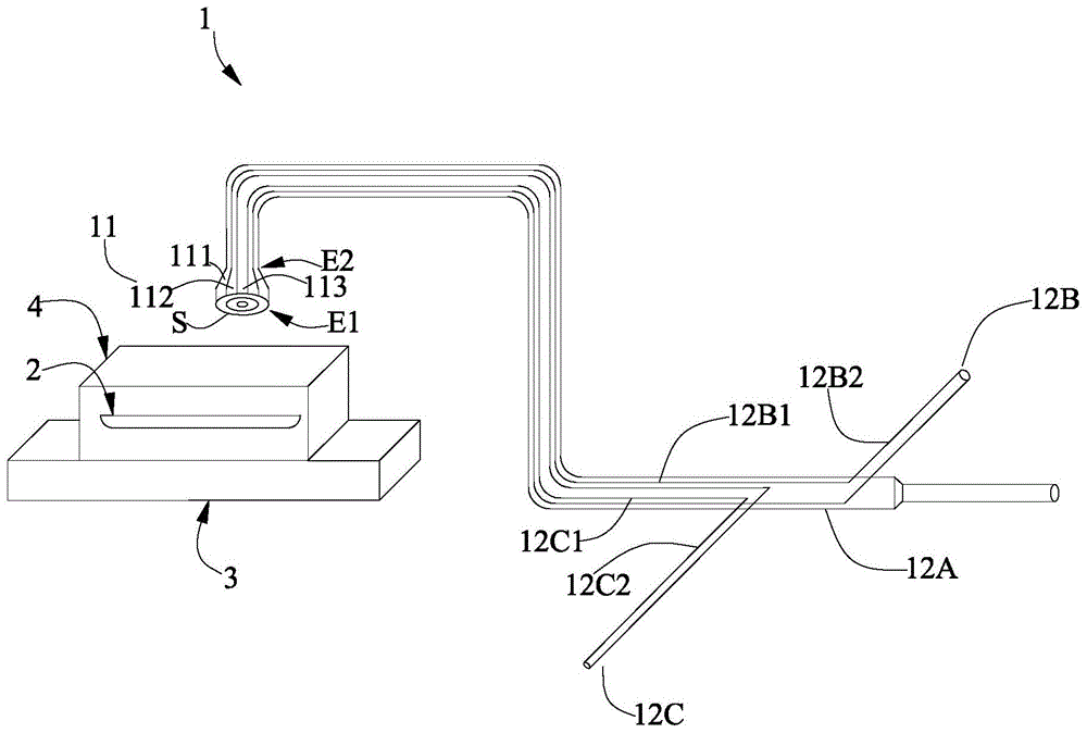
FIG. 1 is a schematic view of a portion of the components of a quartz boat surface coating system according to the present invention. FIG. 2 is an end view of the showerhead 11 of the coating apparatus 1 of the quartz boat surface coating system according to the present invention. FIG. 3 is a schematic diagram of other components of the coating device 1 of the quartz boat surface coating system according to the present invention.
As shown in FIG. 1, the quartz boat surface coating system according to the present invention comprises a coating device 1, wherein the coating device 1 coats the surface of a quartz boat 2. The quartz boat surface coating system may also include a horizontal motion mechanism 3, depending on the application.
The coating device 1 includes a shower head 11. According to the actual situation, the coating device 1 may further include a first tube 12A, a second tube 12B and a third tube 12C. The coating device 1 further includes a shielding gas source 13A, an oxygen gas source 13B, and a component source 13C. According to the actual situation, the coating device 1 may further include a first pipe 14A, a second pipe 14B, a third pipe 14C, a fourth pipe 14D and a fifth pipe 14E. Depending on the actual situation, the coating device 1 may further include a first gas switch 15A, a second gas switch 15B, and a third gas switch 15C. The plating device 1 may further include a second filter 16B and a third filter 16C depending on the actual situation. According to the actual situation, the coating device 1 may further include a first flow meter 17A, a second flow meter 17B, and a third flow meter 17C. According to the actual situation, the film coating device 1 can also comprise a three-way switch V3. According to the actual situation, the filming device 1 can further include a first check valve 18A, a second check valve 18B, a third check valve 18C and a fourth check valve 18D. According to the actual situation, the coating device 1 may further include a first pressure reducing valve 19A, a second pressure reducing valve 19B, a third pressure reducing valve 19C, and a fourth pressure reducing valve 19D. The coating device 1 may further include a vacuum pump 100 according to the actual situation. According to the actual situation, the coating device 1 may further include a pressure gauge 101. Depending on the actual situation, the filming device 1 may further include a pneumatic valve 102. The coating apparatus 1 may further include a component source gas switch 103 according to the actual situation. Depending on the actual situation, the film coating device 1 may further include a cabinet 104.
The spray head 11 is internally provided with a first passage 111, a second passage 112 and a third passage 113 which are arranged in this order from the outside to the inside in the radial direction and are spaced apart from each other (i.e., not communicated with each other). Spray head 11 has axially opposite first end E1 and second end E2. The first end E1 has a first end surface S intersecting the axial direction (preferably perpendicular, i.e., the first end surface S faces forward toward the quartz boat 2 at the time of plating). The first end surface S is provided with a first nozzle 114, a second nozzle 115 and a third nozzle 116 which are arranged in sequence from outside to inside in the radial direction and are spaced apart from each other, i.e. the second nozzle 115 is located radially inside the first nozzle 114 and the third nozzle 116 is located radially inside the second nozzle 115. The first nozzle 114 communicates with the first passage 111, the second nozzle 115 communicates with the second passage 112, and the third nozzle 116 communicates with the third passage 113.
The first end surface S is circular. In the example shown in fig. 1, the area of the first end surface S of the nozzle tip 11 is larger than the area of the cross-section intersecting the axial direction of the second end E2 of the nozzle tip 11. Compared with the injector 11 which is in a cylindrical shape with a uniform cross section, the injector 11 in the example shown in fig. 1 has an unequal cross section and the area of the first end surface S of the injector 11 is the largest, so that the first nozzle 114, the second nozzle 115 and the third nozzle 116 can be arranged in various matching manners in a larger area to meet the requirements such as flow rate, pressure and the like, thereby improving the production flexibility and expanding the adaptability of the injector 11 to quartz boats 2 with different outer diameter specifications.
The first passage 111 is at a second end E2 for communication with a shielding gas source 13A that provides shielding gas having a pressure and velocity. The second passage 112 is in communication at a second end E2 with an oxygen source 13B that provides oxygen gas having a pressure and velocity. The third passage 113 is provided at the second end E2 for communication with a component source 13C that supplies a gas having a pressure and a velocity of the plating film forming component. In one embodiment, the first channel 111 has an outer diameter of 45mm to 49mm, the second channel 112 has an outer diameter of 26mm to 30mm, and the third channel 113 has an outer diameter of 9mm to 11 mm.
The first nozzle 114 is in the form of a closed continuous loop. When the coating device 1 is in operation: since the first nozzle 114 is communicated with the first passage 111 and the first passage 111 is used to be communicated with the shielding gas source 13A at the second end E2, the first nozzle 114 will spray the continuous annular shielding gas, and since the second nozzle 115 and the third nozzle 116 are located radially inside the first nozzle 114, the continuous annular shielding gas sprayed from the first nozzle 114 isolates the gas radially outside the continuous annular shielding gas from the oxygen sprayed from the second nozzle 115 and the coating film forming component of the third nozzle 116 radially inside the continuous annular shielding gas, thereby preventing the gas radially outside the continuous annular shielding gas from affecting the coating film formed (for example, the gas radially outside the continuous annular shielding gas participates in the reaction, introduces external impurities, etc.), and ensuring the purity of the coating film. Preferably, the first nozzle 114 is annular in shape. Because the area in the first nozzle 114 is the area where the oxygen sprayed from the second nozzle 115 and the gas of the component forming the coating film of the third nozzle 116 react to form the coating film, the process of forming the coating film by the reaction is usually violent, the violent reaction shock wave can impact and rebound the continuous annular protective gas sprayed from the first nozzle 114 to generate a reverse shock wave, because the first nozzle 114 adopts a circular ring shape, the reverse shock waves at various positions along the whole circular ring shape can be offset with each other in the diameter direction of the circular ring shape, so that the shock wave and the reverse shock wave in the area in the first nozzle 114 form a good and uniformly distributed mixed wave, and the coating film formed by the reaction carried by the mixed wave is uniformly distributed in the area in the first nozzle 114, thereby improving the uniformity of the coating film. In one embodiment, the inner diameter of the first nozzle 114 is not smaller than the outer diameter of the quartz boat 2, in other words, the area within the inner diameter of the first nozzle 114 is the area where the oxygen gas ejected from the second nozzle 115 and the gas of the coating film forming component of the third nozzle 116 react to form a coating film. From this, when quartz boat 2 horizontal unidirectional movement placed in the middle under shower nozzle 11, the region that forms the coating film can cover quartz boat 2 on the direction vertically with the direction of horizontal motion to only need quartz boat 2 to once at 11 below horizontal unidirectional movement of shower nozzle, just can accomplish the coating film of whole quartz boat 2, improved coating film efficiency.
The second nozzle 115 is circumferentially distributed over the entire circumference. As shown in fig. 2, the second nozzle 115 includes a plurality of through holes 115A. The plurality of through holes 115A are arranged at intervals from one another in one turn in the circumferential direction. Of course, the arrangement of the second nozzle 115 is not limited to the example shown in fig. 2. For example, the second nozzle 115 may have a closed continuous loop shape, as may the closed continuous loop shape of the first nozzle 114. When the plurality of through holes 115A are arranged at intervals from each other in one turn in the circumferential direction, the oxygen flows jetted from the plurality of through holes 115A do not form a continuous ring shape, in other words, the oxygen flows jetted from the plurality of through holes 115A are spaced from each other in the circumferential direction, and the spaces spaced from each other in the circumferential direction allow the second nozzle 115 to communicate radially inward and outward, and the reaction forming the coating film can have a sufficient area for mixing and leveling of the shock wave and the anti-shock wave. When the second nozzle 115 has a closed continuous ring shape, the second nozzle 115 forms a continuous ring of oxygen as well as the isolation effect formed by the first nozzle 114, so that the reaction of forming the coating film is confined to the region within the second nozzle 115. Since the area inside the second nozzle 115 is smaller than the area inside the first nozzle 114, the effect of mixing and smoothing the shock wave and the anti-shock wave is inferior compared to the case where the plurality of through holes 115A are arranged at intervals from each other in one turn in the circumferential direction. The cross-sectional area of each through-hole 115A is smaller than the cross-sectional area of the second passage 112. Thereby increasing the pressure and speed of the oxygen ejected from each through hole 115A by the change of the cross-sectional area, and improving the firmness (or peeling property) of the coating film on the object to be coated (specifically, the quartz boat 2 in this case).
The third nozzle 116 includes a plurality of first perforations 116A and a second perforation 116B. The first perforations 116A are arranged in circles and the first perforations 116A in each circle are circumferentially spaced from each other. In fig. 2, the number of turns of the first perforation 116A is one, but is not limited thereto, and the number of turns of the first perforation 116A is plural. The second perforations 116B are radially inward of the innermost circle of first perforations 116A, preferably the second perforations 116B are centered over the innermost circle of the plurality of first perforations 116A. With the above arrangement of the plurality of first through holes 116A and the one second through hole 116B, the distribution uniformity of the components forming the coating film in the coating reaction in the area inside the second nozzle 115 is facilitated, and the coating material formed on the inner side of the innermost first through hole 116A is prevented from being uneven with the coating material formed at the portion at the innermost first through hole 116A. When the second through hole 116B is not disposed inside the first through hole 116A of the innermost ring, a cavity effect is formed inside the first through hole 116A of the innermost ring, and when the quartz boat 2 travels in the length direction thereof for coating, a coating material formed by reacting the inside of the first through hole 116A of the innermost ring and a coating material formed by reacting the part of the first through hole 116A of the innermost ring are overlapped in thickness due to the travel of the quartz boat 2 in the length direction thereof, thereby causing uneven coating of the quartz boat 2 at different positions in the length direction. The cross-sectional area of each of the first and second holes 116A and 116B is smaller than the cross-sectional area of the third channel 113, so that the gas ejected from each of the first and second holes 116A and 116B, which forms the coating composition, increases the pressure and speed by the change in the cross-sectional area, thereby improving the robustness (or peelability) of the coating on the object to be coated (specifically, the quartz boat 2 in this case). In the example shown in fig. 2, the cross-sectional area of each of the first through holes 116A and the second through holes 116B is smaller than the cross-sectional area of each of the through holes 115A of the second nozzle 115, and the cross-sectional interrelation is designed to ensure that the gases of the components forming the coating react sufficiently to ensure the purity of the coating formed, regardless of whether oxygen participates in the coating forming reaction or independently provides heat. In one embodiment, the third nozzle 116 has an outer diameter no smaller than the outer diameter of the quartz boat 2. Like the aforesaid condition that the internal diameter of first spout 114 is not less than the external diameter of quartz boat 2, when quartz boat 2 level unidirectional movement between two parties under shower nozzle 11, the region that forms the coating film can cover quartz boat 2 on the direction perpendicular with the direction of horizontal motion to only need quartz boat 2 to move in shower nozzle 11 below level unidirectional movement once, just can accomplish the coating film of whole quartz boat 2, improved coating film efficiency, and the purity of the coating film that forms can be better moreover.
As shown in fig. 1, the first, second, and third tubes 12A, 12B, 12C are partially nested within one another in the radial direction. The first pipe 12A connects the first passage 111 and the shielding gas source 13A. The second tube 12B connects the second passage 112 to the oxygen source 13B. The third tube 12C connects the third passage 113 and the component source 13C. The first tube 12A, the second tube 12B and the third tube 12C are configured such that the first passage 111, the second passage 112 and the third passage 113 of the showerhead 11 are connected to the shielding gas source 13A, the oxygen source 13B and the component source 13C, respectively. The first tube 12A, the second tube 12B, and the third tube 12C are partially nested with one another in the radial direction, which contributes to the improvement of the degree of integration and the operational convenience of the components of the plating device 1.
In one embodiment, the first tube 12A has an outer diameter of 27mm to 33mm, the second tube 12B has an outer diameter of 5mm to 20mm, and the third tube 12C has an outer diameter of 5mm to 7 mm. Of course, the size of the quartz boat 2 and the flow rate required for each may be adjusted.
As shown in fig. 1, the second tube 12B includes a first portion 12B1 and a second portion 12B2 connected to each other, an end of the first portion 12B1 of the second tube 12B distal from the second portion 12B2 of the second tube 12B is connected to the second channel 112, and an end of the second portion 12B2 of the second tube 12B distal from the first portion 12B1 of the second tube 12B is connected to the oxygen source 13B; the first portion 12B1 of the second tube 12B is received within the first tube 12A, and the second portion 12B2 of the second tube 12B is bent from the first portion 12B1 of the first tube 12A and sealed off from passing through the first tube 12A.
As shown in fig. 1, the third tube 12C includes a first segment 12C1 and a second segment 12C2 connected to each other, an end of the first segment 12C1 of the third tube 12C distal from the second segment 12C2 of the third tube 12C is connected to the third channel 113, and an end of the second segment 12C2 of the third tube 12C distal from the first segment 12C1 of the third tube 12C is connected to the component source 13C; the first section 12C1 of the third tube 12C is received within the first portion 12B1 of the second tube 12B, and the second section 12C2 of the third tube 12C is bent from the second section 12C2 of the third tube 12C and sealed through the first portion 12B1 of the second tube 12B and the first tube 12A.
The first tube 12A, the second tube 12B, and the third tube 12C adopt the structure shown in fig. 1, which contributes to improvement in the degree of integration of the components of the plating device 1 and convenience in operation. In manufacture, the third tube 12C is first formed (e.g., by injection molding or casting), then the second tube 12B is formed (e.g., by injection molding or casting) over the third tube 12C, and finally the first tube 12A is formed (e.g., by injection molding or casting) over the nested third tube 12C and second tube 12B. Further, the head 11 and the first, second, and third pipes 12A, 12B, and 12C may be integrally formed (for example, by injection molding or casting), the head 11 and the first, second, and third pipes 12A, 12B, and 12C may be separately formed (for example, by injection molding or casting), and then the head 11 is joined to the first, second, and third pipes 12A, 12B, and 12C by welding. The material of the nozzle 11, the first tube 12A, the second tube 12B, and the third tube 12C may be quartz or high temperature resistant metal.
The shielding gas source 13A provides shielding gas having a pressure and a velocity. The shielding gas provided by shielding gas source 13A is nitrogen or an inert gas, preferably argon. The oxygen source 13B provides oxygen having a pressure and a velocity. The component source 13C supplies a gas of a coating film-forming component having a pressure and a velocity. In one embodiment, the gas of the coating-forming component provided by the component source 13C is silane, whereby the oxygen provided by the oxygen source 13B reacts with the silane provided by the component source 13C to form a silicon dioxide coating. In one embodiment, the component source 13C supplies a coating-forming component gas of a mixture of 5% silane and 95% hydrogen. In another embodiment, the gas of the component forming the coating film supplied from the component source 13C is an alkane gas, whereby the oxygen supplied from the oxygen source 13B provides only heat generated by combustion, which causes the alkane gas to thermally crack and thereby form the carbon film. The alkane gas may be methane, butane, acetone, ethylene, etc. Note that, when the thermal cracking is performed by using the alkane gas to form the carbon film, the quartz boat 2 needs to be placed in an environment that is closed and protected by the aforementioned protective gas to perform the coating. When the silica coating film is formed by reacting silane gas with oxygen, it can be performed in an open environment (e.g., natural environment or production plant). The shielding gas source 13A, the oxygen source 13B, and the component source 13C are compressed gas cylinders. By using compressed gas cylinders, the shielding gas source 13A, the oxygen source 13B, and the component source 13C can each provide sufficient power to provide a corresponding gas having a pressure and velocity.
Referring to fig. 3, a first line 14A connects the shielding gas source 13A and the first passage 111. A second conduit 14B connects the oxygen source 13B to the second passage 112. A third conduit 14C connects the component source 13C and the third passage 113. The flow rate of the first pipeline 14A is 150-250sccm, the flow rate of the second pipeline 14B is 35-60sccm, and the flow rate of the third pipeline 14C is 60-90 sccm. These flows can be adjusted according to the actual needs.
The first gas switch 15A, the second gas switch 15B, and the third gas switch 15C are disposed on the first pipeline 14A, the second pipeline 14B, and the third pipeline 14C, respectively. The provision of the first gas switch 15A, the second gas switch 15B, and the third gas switch 15C contributes to the convenience and controllability of the operation of the film coating device 1.
The second filter 16B and the third filter 16C are provided in the second pipe line 14B and the third pipe line 14C, respectively. The second filter 16B is provided downstream of the second gas switch 15B, and the third filter 16C is provided downstream of the third gas switch 15C. Of course, the first line 14A may also be provided with a filter. The second filter 16B is used to filter particles in the oxygen gas supplied from the oxygen gas source 13B, and the third filter 16C is used to filter particles in the shielding gas supplied from the shielding gas source 13A, thereby improving the purity of the formed coating film.
The first flow meter 17A, the second flow meter 17B, and the third flow meter 17C are provided in the first line 14A, the second line 14B, and the third line 14C, respectively. A first flow meter 17A is located downstream of the first gas switch 15A, a second flow meter 17B is located between the second filter 16B and the second gas switch 15B, and a third flow meter 17C is located between the third filter 16C and the third gas switch 15C. The second flow meter 17B and the third flow meter 17C may be mass flow meters, whereby the mass of the respective gases required for the respective components forming the plating film can be accurately reflected. The first flow meter 17A may be a quantum flow meter. Note that quantum flow meters are typically float flow meters, which have less accurate flow control than mass flow meters. Since the flow rate of the shield gas does not need to be controlled as precisely as the flow rate of the gas of the plating film forming component and the oxygen gas, the first flow meter 17A may be selected from this flow meter, and of course, may be modified to a mass flow meter.
The three-way switch V3 is disposed on the first pipeline 14A. The three-way switch V3 has a first port V31, a second port V32, and a third port V33, the first port V31 and the second port V32 being located upstream of the first gas switch 15A, the first port V31 being connected to the shielding gas source 13A (e.g., via the first check valve 18A and the first pressure reducing valve 19A), the second port V32 being located between the first gas switch 15A and the first port V31.
One end of the fourth line 14D is connected to the third line 14C upstream of the third gas switch 15C and near the component source 13C, while the other end of the fourth line 14D is connected to the shielding gas source 13A.
One end of the fifth line 14E is connected to the third port V33 of the three-way switch V3, and the other end of the fifth line 14E is connected to the third line 14C upstream of and adjacent to the third gas switch 15C.
The first check valve 18A, the second check valve 18B, the third check valve 18C, and the fourth check valve 18D are disposed on the first line 14A, the second line 14B, the third line 14C, and the fourth line 14D, respectively. A first check valve 18A is located upstream of the first port V31 of the three-way switch V3, a second check valve 18B is located upstream of the second gas switch 15B, a third check valve 18C is located upstream of the third gas switch 15C, and a fourth check valve 18D is located between the connection of the fourth line 14D and the third line 14C and the shielding gas source 13A. These check valves are provided to prevent external air from flowing back to the upstream portion of the corresponding pipe line located at the corresponding check valve when the plating device 1 is not in operation.
The first, second, third, and fourth pressure reducing valves 19A, 19B, 19C, and 19D are provided in the first, second, third, and fourth pipelines 14A, 14B, 14C, and 14D, respectively. A first pressure reducing valve 19A is located upstream of the first check valve 18A, a second pressure reducing valve 19B is located upstream of the second check valve 18B, a third pressure reducing valve 19C is located upstream of the third check valve 18C, and a fourth pressure reducing valve 19D is located upstream of the fourth check valve 18D. The pressure and flow rate of the gas in the corresponding pipeline can be controlled by the aid of the pressure reducing valves, and accordingly, the required pressure, flow rate (or quality) requirement when the coating is formed can be guaranteed.
The vacuum pump 100 is connected to the third line 14C at a position between the third pressure reducing valve 19C and the third check valve 18C.
A pressure gauge 101 is connected to the third line 14C at a position between the vacuum pump 100 and the third check valve 18C.
The air-operated valve 102 is disposed at a position between the third pressure reducing valve 19C of the third line 14C and the component source 13C. The pneumatic valve 102 is a valve driven by compressed air to achieve flow regulation, which together with the third pressure reducing valve 19C precisely achieves the mass required for the third line 14C to deliver the gas of the film-forming component.
The component source gas switch 103 is connected at a position between the air-operated valve 102 of the third line 14C and the component source 13C. When the silicon dioxide coating film is formed by the reaction of the silane gas and the oxygen gas, the third line 14C is closed in a triple manner by the composition-source gas switch 103, the pneumatic valve 102, and the third gas switch 15C after the coating operation is completed, and the third line 14C is safe in operation.
The cabinet 104 houses the component source 13C and seals the third conduit 14C through the cabinet 104. By adopting the cabinet body 104, the condition that the gas of the components for forming the coating film is flammable and explosive gas can be applied, and the working safety is improved.
The quartz boat 2 has a length of 750mm and an outer diameter of 45 mm. Of course, the size of the quartz boat 2 can be adjusted according to actual needs. The vertical distance between the quartz boat 21 and the spray head 1 is 0.01 m-0.1 m. Of course, the vertical distance between the quartz boat 21 and the shower head 1 can be adjusted according to the actual requirement.
Note that the first gas switch 15A, the first pressure reducing valve 19A, the third gas switch 15C, the third pressure reducing valve 19C, the vacuum pump 100, the air-operated valve 102, the component source gas switch 103, the three-way switch V3, the fourth pressure reducing valve 19D, the fourth line 14D, and the shielding gas source 13A cooperate with each other to function as operations of evacuation and shielding gas purge processing for the first line 14A, the third line 14C, and the fifth line 14E, which will be described later.
The horizontal movement mechanism 3 bears the quartz boat 2, the spray head 11 of the coating device 1 is fixed in position, and the horizontal movement mechanism 3 bears the quartz boat 2 and moves horizontally to pass below the spray head 11. The horizontal movement mechanism 3 is an electric transmission device. Adopt electronic conveyer mode, can accurate settlement transfer rate to quartz boat 2 that horizontal movement mechanism 3 bore can accurately be with the horizontal migration of invariable speed, guarantees quartz boat 2's coating uniformity. The conveying speed of the horizontal movement mechanism 3 is 0.10m/min to 0.30 m/min. Of course, if not mass production, manual transfer (e.g., clamping the quartz boat 2 with clamps and moving the quartz boat 2) may be used.
Finally, the operation of the quartz boat surface plating system according to the present invention will be described with reference to fig. 1 and 3.
The operation of the quartz boat surface plating system includes the steps of: step one, placing a cleaned and preheated quartz boat 2 in a quartz container 4 above a horizontal movement mechanism 3; step two, carrying out vacuumizing and protective gas purging treatment on the first pipeline 14A, the third pipeline 14C and the fifth pipeline 14E; thirdly, the protective gas provided by the protective gas source 13A, the oxygen provided by the oxygen source 13B and the gas of the component for forming the coating film provided by the component source 13C respectively enter the first channel 111, the second channel 112 and the third channel 113 of the showerhead 11 through the first pipeline 14A, the second pipeline 14B and the third pipeline 14C and respectively enter the first pipe 12A, the second pipe 12B and the third pipe 13A, and are respectively sprayed out at the first nozzle 114, the second nozzle 115 and the third nozzle 116 of the showerhead 11 to ignite the oxygen (even the gas of the component (for example, when silane is used)); regulating the gas flow of the first pipeline 14A, the second pipeline 14B and the third pipeline 14C to meet the requirement, and waiting for combustion to a stable state; step five, starting the horizontal movement mechanism 3, conveying the quartz boat 2 to the position right below (and in the middle of) the spray head 11, and starting coating; the quartz boat 2 completely leaves the position right below the spray head 11, and the film coating is finished; sixthly, carrying out vacuumizing and protective gas purging treatment on the first pipeline 14A and the third pipeline 14C and the fifth pipeline 14E; and step seven, after cooling, taking out the quartz boat 2, and finishing the whole operation.
In the first step, the quartz boat cleaning and preheating is as follows: soaking the quartz boat 2 in HF for 3h, cleaning with deionized water, drying, placing in a heating furnace, heating at 400 deg.C for 1-2 hr, taking out, and placing in a transparent quartz container 4 on the horizontal movement mechanism 3.
The second step comprises the following steps: substep a, closing the component source 13C (i.e., the component source 13C itself is provided with a separate switch), closing the first gas switch 15A, the second gas switch 15B and the third gas switch 15C, closing the first pressure reducing valve 19A, the second pressure reducing valve 19B, closing the vacuum pump 100, the three-way switch V3 not communicating with the third line 14C (i.e., the first port V31 and the second port V32 communicating with the first line 14A, the third port V33 not communicating with the first port V31 so that the first line 14A and the third line 14C do not communicate), opening the pneumatic valve 102, the fourth pressure reducing valve 19D, the third pressure reducing valve 19C, the component source gas switch 103, so that the shielding gas of the shielding gas source 13A fills the entire fourth line 14D, the entire fifth line 14E, the portion of the third line 14C between the first gas switch 15A and the component source 13C, when the pressure gauge 101 indicates a pressure greater than 0MPa, closing the fourth pressure reducing valve 19D; substep b, starting the vacuum pump 100 to operate the vacuum pump 100, pumping away the gas (the shielding gas and other gases originally remaining) in the portion between the third check valve 18C of the third pipeline 14C and the component source 13C, and the shielding gas in the entire downstream of the fourth pressure reducing valve 19D of the fourth pipeline 14D, and forming a vacuum in the portion between the third check valve 18C of the third pipeline 14C and the component source 13C, and the entire downstream of the fourth pressure reducing valve 19D of the fourth pipeline 14D; and sub-step C, opening the first pressure reducing valve 19A and the first gas switch 15A to blow off the air in the first pipeline 14A with the shielding gas, then closing the first gas switch 15A, switching the three-way switch V3 to be communicated with the third pipeline 14C (i.e., the first port V31 is communicated with the first pipeline 14A, the third port V33 is communicated with the third pipeline 14C, the first port V31 is communicated with the third port V33, and the second port V32 is not communicated with the first port V31), opening the third gas switch 15C, and blowing off the air at the end of the third pipeline 14C (i.e., the entire downstream section of the third gas switch 15C of the third pipeline 14C) with the shielding gas.
The third step comprises: substep d, opening the gas source 13C, the gas switch 103 for the component source, and the third pressure reducing valve 19C, and then switching the three-way switch V3 to the first line 14A (i.e., the three-way switch V3 is not communicated with the third line 14C, i.e., the first port V31 and the second port V32 are communicated and are communicated with the first line 14A, and the third port V33 is not communicated with the first port V31 so that the first line 14A and the third line 14C are not communicated), at which time the gas (e.g., silane) of the component forming the coating film, supplied from the component source 13C, enters the showerhead 11 and starts the ignition combustion; substep e, opening the second pressure reducing valve 19B and the second gas switch 15B, at which time the oxygen and the silane are mixed and reacted at the showerhead 11; substep f, the first gas switch 15A is opened, and at this time, the three paths of gases at the showerhead 11 work together.
The fourth step comprises the following steps: adjusting a third flow meter of the third pipeline 14C to enable the flow rate to reach 60-90 sccm; adjusting a second flowmeter of the second pipeline 14B to enable the flow rate to reach 35-60 sccm; (ii) a The first flow meter 17A of the first pipe 14A is adjusted to have a flow rate of 150 sccm and 250sccm for 1-3 minutes.
In the fifth step, the horizontal movement mechanism 3 is started, the speed is set to be 0.1-0.3m/min, and the vertical distance between the quartz boat 2 and the spray head 11 is 0.01-0.1 m. When the head of the quartz boat 1 is conveyed to the position right below (centered) the spray head 11, the coating is started, and when the whole quartz boat 2 completely leaves the position right below the spray head 11, the coating is finished.
The sixth step comprises the substeps of: substep g, closing the third pressure reducing valve 19C, the gas switch 103 for the component source and the component source 13C (i.e. the component source 13C is provided with a separate switch), simultaneously switching the three-way switch V3 to the third pipeline 14C (i.e. the three-way switch V3 is communicated with the third pipeline 14C, i.e. the first port V31 and the second port V32 are not communicated, and the third port V33 is communicated with the first port V31 to communicate the first pipeline 14A and the third pipeline 14C), and after the flame is completely extinguished, closing the second pressure reducing valve 19B and the second gas switch 15B; substep h, closing the first pressure reducing valve 19A and the third gas switch 15C, the first gas switch 15A, and switching the three-way switch V3 to the first line 14A (i.e. the first port V31 and the second port V31 are in communication with the first line 14A, and the third port V31 is not in communication with the third line 14C); substep i, opening the fourth pressure reducing valve 19D, the third pressure reducing valve 19C, and the third gas switch 15C (at this time, the component source 13C and the component source gas switch 103 are in a closed state), blowing off the gas of the component for forming a coating film (ignition combustion process or exhaust) supplied from the component source 13C in the third line 14C with a shielding gas (note that the gas downstream of the fifth line 14E and the third check valve 18C is exhausted outward due to the opening of the third check valve 18C), closing the third gas switch 15C, opening the vacuum pump 100, pumping off the portion between the third check valve 18C and the component source 13C of the third line 14C and the residual gas in the entire downstream of the fourth pressure reducing valve 19D of the fourth line 14D, and simultaneously forming a vacuum in the portion from the third check valve 18C to the component source 13C of the third line 14C and the entire downstream of the fourth pressure reducing valve 19D of the fourth line 14D, finally, the vacuum pump 100, the third pressure reducing valve 19C, the fourth pressure reducing valve 19D, and the air-operated valve 102 are turned off.
In step seven, the cooling time is 2-4 hours.
Note that the coating apparatus 1 according to the present invention can be applied to any other suitable object to be coated than the quartz boat surface coating.
The above detailed description describes exemplary embodiments, but is not intended to limit the combinations explicitly disclosed herein. Thus, unless otherwise specified, various features disclosed herein can be combined together to form a number of additional combinations that are not shown for the sake of brevity.