CN110114030B - Device for laser thermal ablation by means of a diffusion catheter and apparatus comprising such a device - Google Patents
Device for laser thermal ablation by means of a diffusion catheter and apparatus comprising such a device Download PDFInfo
- Publication number
- CN110114030B CN110114030B CN201780080371.7A CN201780080371A CN110114030B CN 110114030 B CN110114030 B CN 110114030B CN 201780080371 A CN201780080371 A CN 201780080371A CN 110114030 B CN110114030 B CN 110114030B
- Authority
- CN
- China
- Prior art keywords
- tubular structure
- outer tubular
- coolant
- inner tubular
- electromagnetic radiation
- Prior art date
- Legal status (The legal status is an assumption and is not a legal conclusion. Google has not performed a legal analysis and makes no representation as to the accuracy of the status listed.)
- Active
Links
Images


Classifications
-
- A—HUMAN NECESSITIES
- A61—MEDICAL OR VETERINARY SCIENCE; HYGIENE
- A61B—DIAGNOSIS; SURGERY; IDENTIFICATION
- A61B18/00—Surgical instruments, devices or methods for transferring non-mechanical forms of energy to or from the body
- A61B18/18—Surgical instruments, devices or methods for transferring non-mechanical forms of energy to or from the body by applying electromagnetic radiation, e.g. microwaves
- A61B18/20—Surgical instruments, devices or methods for transferring non-mechanical forms of energy to or from the body by applying electromagnetic radiation, e.g. microwaves using laser
- A61B18/22—Surgical instruments, devices or methods for transferring non-mechanical forms of energy to or from the body by applying electromagnetic radiation, e.g. microwaves using laser the beam being directed along or through a flexible conduit, e.g. an optical fibre; Couplings or hand-pieces therefor
- A61B18/24—Surgical instruments, devices or methods for transferring non-mechanical forms of energy to or from the body by applying electromagnetic radiation, e.g. microwaves using laser the beam being directed along or through a flexible conduit, e.g. an optical fibre; Couplings or hand-pieces therefor with a catheter
-
- A—HUMAN NECESSITIES
- A61—MEDICAL OR VETERINARY SCIENCE; HYGIENE
- A61B—DIAGNOSIS; SURGERY; IDENTIFICATION
- A61B18/00—Surgical instruments, devices or methods for transferring non-mechanical forms of energy to or from the body
- A61B2018/00005—Cooling or heating of the probe or tissue immediately surrounding the probe
- A61B2018/00011—Cooling or heating of the probe or tissue immediately surrounding the probe with fluids
- A61B2018/00023—Cooling or heating of the probe or tissue immediately surrounding the probe with fluids closed, i.e. without wound contact by the fluid
-
- A—HUMAN NECESSITIES
- A61—MEDICAL OR VETERINARY SCIENCE; HYGIENE
- A61B—DIAGNOSIS; SURGERY; IDENTIFICATION
- A61B18/00—Surgical instruments, devices or methods for transferring non-mechanical forms of energy to or from the body
- A61B2018/00571—Surgical instruments, devices or methods for transferring non-mechanical forms of energy to or from the body for achieving a particular surgical effect
- A61B2018/00577—Ablation
-
- A—HUMAN NECESSITIES
- A61—MEDICAL OR VETERINARY SCIENCE; HYGIENE
- A61B—DIAGNOSIS; SURGERY; IDENTIFICATION
- A61B18/00—Surgical instruments, devices or methods for transferring non-mechanical forms of energy to or from the body
- A61B18/18—Surgical instruments, devices or methods for transferring non-mechanical forms of energy to or from the body by applying electromagnetic radiation, e.g. microwaves
- A61B18/20—Surgical instruments, devices or methods for transferring non-mechanical forms of energy to or from the body by applying electromagnetic radiation, e.g. microwaves using laser
- A61B2018/2005—Surgical instruments, devices or methods for transferring non-mechanical forms of energy to or from the body by applying electromagnetic radiation, e.g. microwaves using laser with beam delivery through an interstitially insertable device, e.g. needle
-
- A—HUMAN NECESSITIES
- A61—MEDICAL OR VETERINARY SCIENCE; HYGIENE
- A61B—DIAGNOSIS; SURGERY; IDENTIFICATION
- A61B18/00—Surgical instruments, devices or methods for transferring non-mechanical forms of energy to or from the body
- A61B18/18—Surgical instruments, devices or methods for transferring non-mechanical forms of energy to or from the body by applying electromagnetic radiation, e.g. microwaves
- A61B18/20—Surgical instruments, devices or methods for transferring non-mechanical forms of energy to or from the body by applying electromagnetic radiation, e.g. microwaves using laser
- A61B18/22—Surgical instruments, devices or methods for transferring non-mechanical forms of energy to or from the body by applying electromagnetic radiation, e.g. microwaves using laser the beam being directed along or through a flexible conduit, e.g. an optical fibre; Couplings or hand-pieces therefor
- A61B2018/2205—Characteristics of fibres
- A61B2018/2211—Plurality of fibres
- A61B2018/2216—Braided or helically wound
-
- A—HUMAN NECESSITIES
- A61—MEDICAL OR VETERINARY SCIENCE; HYGIENE
- A61B—DIAGNOSIS; SURGERY; IDENTIFICATION
- A61B18/00—Surgical instruments, devices or methods for transferring non-mechanical forms of energy to or from the body
- A61B18/18—Surgical instruments, devices or methods for transferring non-mechanical forms of energy to or from the body by applying electromagnetic radiation, e.g. microwaves
- A61B18/20—Surgical instruments, devices or methods for transferring non-mechanical forms of energy to or from the body by applying electromagnetic radiation, e.g. microwaves using laser
- A61B18/22—Surgical instruments, devices or methods for transferring non-mechanical forms of energy to or from the body by applying electromagnetic radiation, e.g. microwaves using laser the beam being directed along or through a flexible conduit, e.g. an optical fibre; Couplings or hand-pieces therefor
- A61B2018/2255—Optical elements at the distal end of probe tips
- A61B2018/2261—Optical elements at the distal end of probe tips with scattering, diffusion or dispersion of light
-
- A—HUMAN NECESSITIES
- A61—MEDICAL OR VETERINARY SCIENCE; HYGIENE
- A61B—DIAGNOSIS; SURGERY; IDENTIFICATION
- A61B18/00—Surgical instruments, devices or methods for transferring non-mechanical forms of energy to or from the body
- A61B18/18—Surgical instruments, devices or methods for transferring non-mechanical forms of energy to or from the body by applying electromagnetic radiation, e.g. microwaves
- A61B18/20—Surgical instruments, devices or methods for transferring non-mechanical forms of energy to or from the body by applying electromagnetic radiation, e.g. microwaves using laser
- A61B18/22—Surgical instruments, devices or methods for transferring non-mechanical forms of energy to or from the body by applying electromagnetic radiation, e.g. microwaves using laser the beam being directed along or through a flexible conduit, e.g. an optical fibre; Couplings or hand-pieces therefor
- A61B2018/2255—Optical elements at the distal end of probe tips
- A61B2018/2288—Optical elements at the distal end of probe tips the optical fibre cable having a curved distal end
Landscapes
- Health & Medical Sciences (AREA)
- Surgery (AREA)
- Physics & Mathematics (AREA)
- Life Sciences & Earth Sciences (AREA)
- Heart & Thoracic Surgery (AREA)
- Medical Informatics (AREA)
- Nuclear Medicine, Radiotherapy & Molecular Imaging (AREA)
- Electromagnetism (AREA)
- Engineering & Computer Science (AREA)
- Biomedical Technology (AREA)
- Optics & Photonics (AREA)
- Otolaryngology (AREA)
- Molecular Biology (AREA)
- Animal Behavior & Ethology (AREA)
- General Health & Medical Sciences (AREA)
- Public Health (AREA)
- Veterinary Medicine (AREA)
- Laser Surgery Devices (AREA)
- Lining Or Joining Of Plastics Or The Like (AREA)
- Laser Beam Processing (AREA)
Abstract
本发明涉及一种装置,所述装置包括:外部管状结构(21),其具有封闭的末端端部;‑内部管状结构(23),其被定位在所述外部管状结构中,并且所述内部管状结构具有侧壁并且限定内部容积,所述侧壁具有末端端部,所述内部管状结构被配置成接收光导(27);其中,在所述外部管状结构(21)和所述内部管状结构(23)之间形成用于冷却剂循环的第一间隙(25);所述外部管状结构(21)或所述内部管状结构(23)的至少一部分对在所述光导(27)中传播的电磁辐射是扩散的。

The invention relates to a device comprising: an outer tubular structure (21) having a closed terminal end; an inner tubular structure (23) positioned in said outer tubular structure and said inner a tubular structure having side walls having terminal ends and defining an inner volume, the inner tubular structure being configured to receive a light guide (27); wherein between the outer tubular structure (21) and the inner tubular structure ( 23 ) forming a first gap ( 25 ) for coolant circulation; at least a portion of said outer tubular structure ( 21 ) or said inner tubular structure ( 23 ) to Electromagnetic radiation is diffuse.
Description
技术领域technical field
本发明涉及用于热消融处理的医疗装置和设备。本文描述的实施例涉及激光热消融系统。The present invention relates to medical devices and apparatus for thermal ablation treatment. Embodiments described herein relate to laser thermal ablation systems.
背景技术Background technique
热消融经常用于医学中以经由微创方法去除组织,例如,实体癌组织。在本领域中已经使用了几种形式的能量,包括射频、微波和激光。其它方法使用冷冻消融,即,使用冷却循环破坏病理组织的部分;或不可逆的电穿孔,其施加电脉冲以不可逆的方式损伤细胞膜。Thermal ablation is often used in medicine to remove tissue, eg, solid cancer tissue, via minimally invasive methods. Several forms of energy have been used in the art, including radio frequency, microwaves and lasers. Other methods use cryoablation, ie, the use of cooling cycles to destroy parts of pathological tissue; or irreversible electroporation, which applies electrical pulses to irreversibly damage cell membranes.
在激光热消融的领域中,使用了这样的装置,即,所述装置包括形成插入针的导管,纤维通过所述插入针插入待处理的区域中。In the field of laser thermal ablation, devices are used which comprise a catheter forming an insertion needle through which fibers are inserted into the area to be treated.
实质上,为了破坏癌细胞,电磁辐射(通常是激光辐射)被带入癌性肿块中。为了到达癌性肿块,提供了这样一种装置,即,所述装置具有导管或可透过的针,光纤在所述导管或可透过的针内被引导。在一些情况下,光纤被定位在其中必须施加激光辐射且收回导管的点中。裸纤维与组织直接接触,所述组织用电磁辐射照射。在其它已知的实施例中,纤维在导管中被引导并且保持在其内部,所述导管由允许激光辐射通过的材料制成。冷却剂在导管中循环以去除热量和避免组织碳化现象。Essentially, electromagnetic radiation (usually laser radiation) is directed into the cancerous mass in order to destroy the cancer cells. To reach a cancerous mass, a device is provided that has a catheter or a permeable needle within which an optical fiber is guided. In some cases, the optical fiber is positioned in the point where the laser radiation must be applied and the catheter retracted. Bare fibers are in direct contact with tissue, which is irradiated with electromagnetic radiation. In other known embodiments, the fibers are guided and held inside a conduit made of a material that allows the passage of laser radiation. A coolant is circulated through the catheter to remove heat and avoid tissue carbonization.
为了处理更大体积的组织,使用多根光纤,每根光纤都使用插入针被引导到合适的位置中。目前,使用扁平尖端纤维的消融标准设想到使用5W和1200J至1800J的剂量。为了增大相对于纤维的轴线在横向方向上的体积,采用若干光纤的插入,而如果待增大在轴向方向上的消融体积,则这涉及收回光纤和依次释放多个剂量的能量的操纵。To address larger volumes of tissue, multiple optical fibers are used, each guided into place using an insertion needle. Currently, the standard of ablation using flat-tip fibers envisages the use of 5W and a dose of 1200J to 1800J. In order to increase the volume in the transverse direction with respect to the axis of the fiber, the insertion of several fibers is employed, whereas if the ablation volume in the axial direction is to be increased, this involves the manipulation of retracting the fibers and sequentially releasing multiple doses of energy .
借助裸纤维涂敷器获得较大体积的消融的主要限制之一是碳化层的形成以及在碳化后面的组织的第一部分中的严重脱水,所述碳化层在通过纤维近侧区域中的组织升华而留下的腔体的壁中产生。这些现象阻碍激光扩散到肿瘤的远侧部分,限制了该装置的效用。对在最靠近纤维的组织中发展的光和热的扩散的阻碍意味着在靠近纤维尖端的这些部分中温度升高,随后组织升华。这种相位变化消耗了激光能量,所述激光能量可能以其它方式导致远侧区域中的组织变性。结果,对于输送的等同总量的能量而言,经受所需处理的体积较小。能量的进一步施用基本上有助于增大最靠近纤维尖端的组织的升华,而不会有助于增大处理过的体积,所述最靠近纤维尖端的组织升高到更高的温度。One of the main limitations in obtaining larger volumes of ablation with bare fiber applicators is the formation of a carbonized layer that sublimates through the tissue in the proximal region of the fiber and severe dehydration in the first part of the tissue following the carbonization while leaving the walls of the cavity produced. These phenomena hinder the diffusion of laser light to the distal part of the tumor, limiting the utility of the device. The hindrance to the diffusion of light and heat that develops in the tissue closest to the fiber means that in these parts near the fiber tip the temperature rises, followed by sublimation of the tissue. This phase change consumes laser energy that might otherwise cause tissue degeneration in the distal region. As a result, the volume undergoing the required treatment is smaller for an equivalent total amount of energy delivered. Further application of energy substantially contributes to increasing the sublimation of the tissue closest to the fiber tip, which is raised to a higher temperature, without contributing to increasing the treated volume.
由于在纤维尖端上和在最靠近它的空间中的较高密度功率而发生了碳化,其中发生脱水并且发生组织的干燥和升华,产生了碳化腔体和凝结的周围组织的环。这产生了屏障以屏蔽朝向远离纤维尖端较远的组织的热扩散。不能增大输送的功率,以便将热能输送到碳化和凝结区域之外,如使用光纤的锋面发射产生长而窄的损伤,这与通常在肿瘤块中看到的圆形形状不相容。此外,激光功率增大超过最佳值而导致了由热消融试图实现的对细胞的不可逆损伤过程的恶化。实际上,在较高功率下,在最靠近纤维的区域中激发温度的快速升高,其快速脱水、干燥,这是因为它们没有由较远的区域供应流体。严重脱水的组织区域对激光的透射变得不透明并且阻碍了热量在周围体积中的传播。Carbonization occurs due to higher density power on the fiber tip and in the space closest to it, where dehydration occurs and drying and sublimation of the tissue occurs, creating a carbonized cavity and a ring of coagulated surrounding tissue. This creates a barrier to shield the heat from spreading towards the tissue further away from the fiber tip. The power delivered cannot be increased in order to deliver thermal energy beyond the area of carbonization and coagulation, as frontal emission using fiber optics produces long, narrow lesions that are incompatible with the circular shape typically seen in tumor masses. Furthermore, increasing the laser power beyond the optimal value leads to aggravation of the irreversible damage process to the cells that thermal ablation attempts to achieve. In fact, at higher powers a rapid increase in temperature is induced in the regions closest to the fibres, which dehydrate, dry quickly, since they are not supplied with fluid by the more distant regions. Severely dehydrated tissue regions become opaque to laser transmission and impede heat transfer in the surrounding volume.
为了解决这些问题,已经产生了冷却的热消融装置,在所述冷却的热消融装置中冷却剂在其中插入有纤维的导管中循环,并且去除热量。更具体地,已知类型的冷却装置包括具有封闭的远侧端部的外部导管,在所述封闭的远侧端部内布置有管道,所述管道容纳光导,通常地为光纤。在内部管道和外部导管之间限定有间隙,所述间隙与在内部导管和光纤之间限定的第二间隙流体连通。冷却剂在两个间隙中循环。冷却剂从处理区域去除热量,避免了在纤维周围的组织的过热和碳化。In order to solve these problems, cooled thermal ablation devices have been produced in which a coolant is circulated in a catheter in which fibers are inserted, and heat is removed. More specifically, a known type of cooling device comprises an external conduit having a closed distal end inside which a duct is arranged, said duct housing a light guide, usually an optical fiber. A gap is defined between the inner conduit and the outer conduit, the gap being in fluid communication with a second gap defined between the inner conduit and the optical fiber. Coolant circulates in both gaps. The coolant removes heat from the treatment area, avoiding overheating and carbonization of the tissue surrounding the fibers.
US-A-7.270.656描述了一种用于激光热消融的装置,所述装置包括:外部管状结构,其具有封闭的末端端部和内部纵向腔体;和内部管状结构,其具有侧壁,所述侧壁限定以末端端部终止的内部纵向容积。在内部管状结构内插入光导,以将激光辐射承载到末端端部。内部管状结构在外部管状结构的内部纵向腔体中纵向地延伸。在外部管状结构和内部管状结构之间形成第一冷却剂循环间隙。内部管状结构的末端端部是敞开的而使间隙和内部管状结构的内部容积流体连通,以从处理区域去除热量。这样,实现了该装置的效用的改进。US-A-7.270.656 describes a device for laser thermal ablation comprising: an outer tubular structure with a closed distal end and an inner longitudinal cavity; and an inner tubular structure with side walls , the side walls define an interior longitudinal volume terminating in a terminal end. A light guide is inserted within the inner tubular structure to carry the laser radiation to the distal end. The inner tubular structure extends longitudinally within the inner longitudinal cavity of the outer tubular structure. A first coolant circulation gap is formed between the outer tubular structure and the inner tubular structure. The distal end of the inner tubular structure is open to place the gap in fluid communication with the interior volume of the inner tubular structure to remove heat from the treatment zone. In this way, an improvement in the utility of the device is achieved.
然而,利用该解决方案实现的结果可以受到进一步改进,尤其为了获得组织照射的更好的扩散和均匀性。However, the results achieved with this solution can be further improved, especially in order to obtain better diffusion and homogeneity of tissue irradiation.
发明内容Contents of the invention
为此目的,根据本文描述的实施例,提供一种用于激光热消融的装置,所述装置包括:外部管状结构,其具有封闭的末端端部;和内部管状结构,其被定位在所述外部管状结构中,并且所述内部管状结构具有侧壁并且限定内部容积,所述侧壁具有末端端部,所述内部管状结构被配置成接收光导。在所述外部管状结构和所述内部管状结构之间形成第一冷却剂循环间隙。所述外部管状结构和/或所述内部管状结构的至少一部分对在所述光导中传播的电磁辐射是扩散的。所述外部管状结构和所述内部管状结构中的另一个对所述电磁辐射是透明的或扩散的。例如,可以设想到,所述内部管状结构和所述外部管状结构两者具有至少一个扩散部分。在其它实施例中,所述外部管状结构可以被设想为具有至少一个扩散部分,并且所述内部管状结构可以被设想为具有透明部分。在又一些其它实施例中,所述外部管状结构可以被设想为具有透明部分,并且所述内部管状结构可以被设想为具有至少一个扩散部分。To this end, according to embodiments described herein, there is provided a device for laser thermal ablation comprising: an outer tubular structure having a closed distal end; and an inner tubular structure positioned on the In an outer tubular structure, and the inner tubular structure has side walls and defines an inner volume, the side walls have terminal ends, the inner tubular structure being configured to receive a light guide. A first coolant circulation gap is formed between the outer tubular structure and the inner tubular structure. At least a portion of the outer tubular structure and/or the inner tubular structure is diffusive to electromagnetic radiation propagating in the light guide. The other of the outer tubular structure and the inner tubular structure is transparent or diffuse to the electromagnetic radiation. For example, it is conceivable that both the inner tubular structure and the outer tubular structure have at least one diverging portion. In other embodiments, the outer tubular structure may be conceived as having at least one diffuser portion and the inner tubular structure may be conceived as having a transparent portion. In yet other embodiments, the outer tubular structure may be conceived with a transparent portion and the inner tubular structure may be conceived with at least one diffuser portion.
在某些实施例中,所述内部管状结构和所述外部管状结构两者通过挤压形成,并且在它们的整个轴向延伸部上可以具有相同的光学特性。In some embodiments, both the inner tubular structure and the outer tubular structure are formed by extrusion and may have the same optical properties throughout their axial extension.
如果仅所述内部管状结构和所述外部管状结构的一部分是透明的和/或扩散的,则所述扩散部分或所述扩散部分和所述透明部分被定位成沿着所述装置的轴向发展至少部分地处于相同位置中,使得由所述光导在所述内部管状结构中承载的电磁辐射可以扩散在所述装置的外部上。If only a portion of the inner tubular structure and the outer tubular structure is transparent and/or diffuse, the diffuse portion or the diffuse portion and the transparent portion are positioned along the axial direction of the device The developments are at least partially in the same position so that electromagnetic radiation carried by the light guide in the inner tubular structure can be diffused on the exterior of the device.
可以在所述内部管状结构的内部容积中容纳有光导。所述光导可以包括光纤,并且任选地包括扩散器,所述扩散器位于所述光纤的尖端的前方并且从所述光纤的尖端朝向所述装置的尖端延伸。这样,在所述内部管状结构和所述光导之间形成用于冷却剂循环的第二间隙。A light guide may be housed within the interior volume of the inner tubular structure. The light guide may comprise an optical fiber and optionally a diffuser positioned forward of the tip of the optical fiber and extending from the tip of the optical fiber towards the tip of the device. In this way, a second gap for coolant circulation is formed between the inner tubular structure and the light guide.
所述扩散器可以包括芯部和包围所述芯部的护套;所述芯部和所述护套中的至少一个可以在所述光导中传播的电磁辐射的波长下是扩散的。例如,根据某些实施例,所述芯部使用在所述光导中传播的电磁辐射的波长下扩散的材料制成,并且所述护套使用在所述光导中传播的电磁辐射的波长下透明的材料制成。在其它实施例中,所述芯部使用在所述光导中传播的电磁辐射的波长下扩散的材料制成,并且所述护套使用在所述光导中传播的电磁辐射的波长下扩散的材料制成。在又一些其它目前优选的实施例中,所述芯部使用在所述光导中传播的电磁辐射的波长下透明的材料制成,并且所述护套使用在所述光导中传播的电磁辐射的波长下扩散的材料制成。The diffuser may include a core and a sheath surrounding the core; at least one of the core and the sheath may be diffuse at a wavelength of electromagnetic radiation propagating in the light guide. For example, according to some embodiments, the core is made of a material that diffuses at the wavelength of electromagnetic radiation propagating in the light guide, and the sheath is transparent at the wavelength of electromagnetic radiation propagating in the light guide. made of materials. In other embodiments, the core is made of a material that diffuses at the wavelength of electromagnetic radiation propagating in the light guide, and the sheath uses a material that diffuses at the wavelength of electromagnetic radiation propagating in the light guide production. In still other presently preferred embodiments, the core is made from a material that is transparent at the wavelength of the electromagnetic radiation propagating in the light guide, and the sheath uses a material that is transparent to the wavelength of the electromagnetic radiation propagating in the light guide. Made of materials that diffuse at wavelengths.
为了改进电磁辐射的扩散效果,在某些实施例中,所述光导的至少一部分被弯曲以形成相对于所述装置的轴向方向倾斜的侧表面。例如,所述光导可以包括扩散器,所述扩散器可以具有至少部分螺旋形的形状,围绕所述内部管状结构和/或所述外部管状结构的纵向轴线形成至少一个绕组。所述扩散器的螺旋形状促进电磁辐射的发射,并且因此允许所述辐射更好地朝向在使用期间插入有所述装置的组织扩散。In order to improve the diffusion effect of the electromagnetic radiation, in some embodiments at least a portion of the light guide is curved to form side surfaces inclined with respect to the axial direction of the device. For example, the light guide may comprise a diffuser, which may have an at least partially helical shape, forming at least one winding around the longitudinal axis of the inner tubular structure and/or the outer tubular structure. The helical shape of the diffuser facilitates the emission of electromagnetic radiation and thus allows better diffusion of said radiation towards the tissue into which the device is inserted during use.
整个所述扩散器不必具有螺旋形发展。在某些实施例中,所述扩散器可以被设想为具有直线部分和螺旋部分。优选地,所述直线部分是与所述光纤相邻,而所述螺旋部分相对于所述光纤位于远侧位置中。The entire diffuser does not have to have a helical development. In some embodiments, the diffuser may be conceived as having a straight portion and a helical portion. Preferably, said straight portion is adjacent to said optical fiber and said helical portion is in a distal position relative to said optical fiber.
为了实现所述装置的更好的操作,尤其为了获得电磁辐射的更均匀的侧向照射,通常是来自所述内部管状结构的内部的激光辐射,在所述外部管状结构和所述内部管状结构之间可以定位有第一间隔物,所述第一间隔物围绕所述外部管状结构的纵向轴线螺旋形地发展。所述间隔物的螺旋形发展降低了所述间隔物对所述冷却剂的流动的负面影响。已知的装置通常设想到与所述外部管状结构的轴线平行的至少三个直线间隔物,其目的是保持所述外部管状结构和所述内部管状结构彼此共轴。这种较多数量的间隔物的存在显著地减小了用于供冷却剂通过的截面。In order to achieve a better operation of the device, in particular to obtain a more uniform lateral irradiation of electromagnetic radiation, usually laser radiation from the inside of the inner tubular structure, between the outer tubular structure and the inner tubular structure There may be positioned therebetween a first spacer that develops helically around the longitudinal axis of the outer tubular structure. The helical development of the spacers reduces the negative influence of the spacers on the flow of the coolant. Known devices generally envisage at least three rectilinear spacers parallel to the axis of the outer tubular structure, the purpose of which is to keep the outer tubular structure and the inner tubular structure coaxial with each other. The presence of this higher number of spacers significantly reduces the cross-section for the passage of the coolant.
为了保持所述内部管状结构和位于所述内部管状结构内的光导基本彼此共轴,可以在所述内部管状结构和所述光导之间形成的间隙中放置有第二间隔物,所述第二间隔物围绕所述内部管状结构的纵向轴线螺旋形地发展。在其它实施例中,如果所述扩散器具有至少部分螺旋形的形状,则所述第二间隔物可以被省略,并且所述扩散器的形状保证相对于所述内部管状结构共轴定位。In order to keep the inner tubular structure and the light guide within the inner tubular structure substantially coaxial with each other, a second spacer may be placed in the gap formed between the inner tubular structure and the light guide, the second The spacer develops helically around the longitudinal axis of the inner tubular structure. In other embodiments, the second spacer may be omitted if the diffuser has an at least partially helical shape, and the shape of the diffuser ensures coaxial positioning relative to the inner tubular structure.
在某些实施例中,如果设想到两个间隔物,则它们可以具有沿相反方向的螺旋形绕组。In some embodiments, if two spacers are envisioned, they may have helical windings in opposite directions.
优选地,为了实现冷却剂的更高效循环,所述内部管状结构的侧壁可以包括用于供冷却剂通过的一个或多个孔口或开口。在有利的实施例中,提供多个侧向开口,使所述第一间隙与所述内部管状结构的内部容积流体连通。Preferably, in order to achieve more efficient circulation of the coolant, the side walls of the inner tubular structure may comprise one or more apertures or openings for passage of the coolant. In an advantageous embodiment, a plurality of lateral openings are provided for fluid communication of said first gap with the inner volume of said inner tubular structure.
为了获得均匀的流动,在所述内部管状结构的壁中形成的开口或孔口优选地布置在围绕所述内部管状结构的纵向轴线的交错位置中。In order to obtain a uniform flow, the openings or orifices formed in the wall of the inner tubular structure are preferably arranged in staggered positions around the longitudinal axis of the inner tubular structure.
在有利的实施例中,所述侧向开口沿着所述内部管状结构的纵向延伸部按顺序布置。In an advantageous embodiment, said lateral openings are arranged sequentially along the longitudinal extension of said inner tubular structure.
所述内部管状结构的末端端部可以是敞开的,使得冷却剂的流动既可以通过形成在所述内部管状结构的壁中的所述侧向开口,也可以通过所述内部管状结构的开口端部。然而,在优选的实施例中,如果所述内部管状结构的末端端部闭合,则获得改进的冷却剂循环。这样,冷却剂仅流过所述侧向开口。The terminal end of the inner tubular structure may be open such that the flow of coolant is either through the lateral opening formed in the wall of the inner tubular structure or through the open end of the inner tubular structure department. However, in a preferred embodiment, improved coolant circulation is obtained if the terminal ends of the inner tubular structure are closed. In this way, coolant flows only through said lateral openings.
可以借助合适的机械表面加工或借助表面化学处理而使得所述内部管状结构和/或所述外部管状结构扩散。在某些实施例中,可以通过在形成所述内部管状结构和/或外部管状结构的基础材料中添加合适的扩散颗粒或粉末而使得所述内部管状结构和/或所述外部管状结构扩散。基础材料可以是石英、玻璃、树脂或其它聚合物材料。The inner tubular structure and/or the outer tubular structure may be diffused by means of a suitable mechanical surface treatment or by means of a surface chemical treatment. In some embodiments, the inner tubular structure and/or the outer tubular structure may be made diffuse by adding suitable diffusing particles or powders to the base material from which the inner tubular structure and/or outer tubular structure is formed. The base material can be quartz, glass, resin or other polymeric materials.
所述装置可以包括与包含冷却回路和激光源的设备连接的光学液压连接部。所述光学液压连接部可以包括多个柔性管,形成用于供应冷却剂的第一冷却通道、用于从所述装置去除冷却剂的第二冷却通道以及光学通道,在所述光学通道中容纳有光导。The device may comprise an optohydraulic connection to a device comprising a cooling circuit and a laser source. The optical hydraulic connection may comprise a plurality of flexible tubes forming a first cooling channel for supplying coolant, a second cooling channel for removing coolant from the device, and an optical channel in which the There is a light guide.
根据另一方面,本文描述了一种用于激光热消融的设备,所述设备包括:如上所述的装置;激光源;冷却回路;控制单元。According to another aspect, an apparatus for laser thermal ablation is described herein, said apparatus comprising: a device as described above; a laser source; a cooling circuit; a control unit.
所述设备还可以包括以下元件、部件或装置中的一个或多个:用于冷却剂循环的泵;流量计,其被配置成检测冷却剂的流量;压力传感器,其被配置成检测冷却回路的至少一个点中的冷却剂的压力;用于将冷却剂进给到所述装置的罐;用于从所述装置收集冷却剂的罐;用于储存和再循环冷却剂的罐;用于从冷却剂去除热量的构件。The apparatus may also include one or more of the following elements, components or devices: a pump for circulation of the coolant; a flow meter configured to detect the flow of the coolant; a pressure sensor configured to detect the cooling circuit The pressure of the coolant in at least one point of the; a tank for feeding the coolant to the device; a tank for collecting the coolant from the device; a tank for storing and recirculating the coolant; A component that removes heat from the coolant.
附图说明Description of drawings
根据本说明书和附图,将更好地理解本发明,附图示出本发明的非限制性实际实施例。更具体地,附图示出:The invention will be better understood from the description and from the accompanying drawings, which show a non-limiting practical embodiment of the invention. More specifically, the accompanying drawings show:
图1是根据一个实施例的装置的整体视图;Figure 1 is an overall view of a device according to one embodiment;
图2是沿图1的线II-II截取的剖视图;Fig. 2 is a sectional view taken along line II-II of Fig. 1;
图3是根据包含有导管的纵向轴线的平面的剖视图,所述导管形成图1中所示的所述装置的远侧元件;Figure 3 is a cross-sectional view according to a plane containing the longitudinal axis of the catheter forming the distal element of the device shown in Figure 1;
图4是沿图1的线IV-IV截取的横向剖视图;Fig. 4 is a transverse sectional view taken along line IV-IV of Fig. 1;
图5是在不同实施例中的根据包含有导管的纵向轴线的平面的剖视图;Figure 5 is a cross-sectional view according to a plane containing the longitudinal axis of the catheter, in various embodiments;
图6是表示根据供应压力的冷却剂流量的图表。FIG. 6 is a graph showing coolant flow rate according to supply pressure.
图7是在又一个实施例中的根据包含有导管的纵向轴线的平面的剖视图。Figure 7 is a cross-sectional view according to a plane containing the longitudinal axis of the catheter in yet another embodiment.
图8是在又一个实施例中的根据包含有导管的纵向轴线的平面的剖视图。Figure 8 is a cross-sectional view according to a plane containing the longitudinal axis of the catheter in yet another embodiment.
图9、图10、图11示出导管的末端部分及其所包含的部件的实施例;Fig. 9, Fig. 10, Fig. 11 show the embodiment of the end part of catheter and the parts that it comprises;
图12的(A)至(H)是封闭导管的末端元件的实施例;(A) to (H) of Fig. 12 are the embodiment of the terminal element of closure catheter;
图13是具有可胀大元件的导管的实施例;Figure 13 is an embodiment of a catheter with expandable elements;
图14和图15示出使用本文描述的装置的设备的冷却回路的图解;Figures 14 and 15 show a diagram of a cooling circuit of a device using the device described herein;
图16和图17示出在两个实施例中的根据本发明的设备的图解;Figures 16 and 17 show diagrams of the device according to the invention in two embodiments;
图18是在可替代的实施例中插入内部管状结构中的光导的末端部分的轴测图。Figure 18 is an isometric view of an end portion of a light guide inserted into an inner tubular structure in an alternative embodiment.
图19、图20、图21是光导的可替代实施例并且尤其是光导的末端扩散器的可替代实施例;Figures 19, 20, 21 are alternative embodiments of the light guide and in particular of the end diffuser of the light guide;
图22A至图22I是在各种实施例中的光导扩散器的发射图;22A-22I are emission diagrams of light guide diffusers in various embodiments;
图23A至图23C是光导的末端元件的实施例。23A-23C are embodiments of end elements of a light guide.
具体实施方式Detailed ways
以下对示例性实施例的详细描述参考附图。不同附图中的相同附图标记指示相同或相似的元件。另外,附图不一定按比例绘制。而且,以下详细的描述不限制本发明。相反,本发明的范围由所附权利要求书限定。The following detailed description of the exemplary embodiments refers to the accompanying drawings. The same reference numbers in different drawings indicate the same or similar elements. Additionally, the drawings are not necessarily drawn to scale. Also, the following detailed description does not limit the invention. Rather, the scope of the invention is defined by the appended claims.
整个说明书中对“一个实施例”或“实施例”或“某些实施例”的引用意味着结合实施例描述的特定特征、结构或特性被包括在所公开的主旨的至少一个实施例中。因此,在整个说明书中在各处出现的短语“在一个实施例中”或“在实施例中”或“在某些实施例中”不一定是指相同的一个或多个实施例。此外,特定特征、结构或特性可以在一个或多个实施例中以任何合适的方式组合。首先参照图1,在第一实施例中,附图标记1指示根据本发明的装置。装置1包括远侧部分3和与下面描述的包含激光源的设备连接的光学液压连接部5。光学液压连接部5可以包括三个通道,其在图2的剖视图中更详细地示出。第一通道7和第二通道9用于允许冷却剂在如下所述的导管内循环,如下所述的导管形成装置1的远侧部分3的一部分。第三通道11用于允许光导通过,例如,光纤13。在某些实施例中,如下面更详细地描述的,在装置1的导管的远侧端部中发现的、与温度传感器连接的连接部也可以穿过通道11。Reference throughout this specification to "one embodiment" or "an embodiment" or "certain embodiments" means that a particular feature, structure, or characteristic described in connection with the embodiments is included in at least one embodiment of the disclosed subject matter. Thus, appearances of the phrase "in one embodiment" or "in an embodiment" or "in some embodiments" in various places throughout this specification are not necessarily referring to the same embodiment or embodiments. Furthermore, the particular features, structures or characteristics may be combined in any suitable manner in one or more embodiments. Referring first to Figure 1, in a first embodiment,
在图1和图2中所示的实施例中,通道7、通道9和通道11基本在同一平面上,并且通道11布置在通道7和通道9之间。这样,通道7和通道9彼此间隔开,以限制相互的热交换。通道7、通道9和通道11被封闭在柔性管10内,形成共用的护套,其将所有通道7、通道9和通道11保持在一起直到末端元件12,通道7、通道9和通道11分别从所述末端元件12离开,终止于相应的连接器15、17和19。这些连接器用于将装置1连接到包含激光源和冷却回路的设备,所述激光源将激光辐射注射到光纤13中,所述冷却回路促使冷却剂通过通道7和9循环。In the embodiment shown in FIGS. 1 and 2 , channel 7 ,
图3示出在根据包含纵向轴线的平面的横截面中的装置1的远侧部分2,并且图4示出沿图3的线IV-IV截取的所述远侧部分的横截面。Fig. 3 shows the
装置1的远侧部分包括外部管状结构21,其由例如导管或针构成。外部管状结构21的末端端部由封闭元件22封闭。在下文中,外部管状结构21也将简称为导管。The distal part of the
在外部管状结构21的内部,布置有内部管状结构23。在图3中所示的实施例中,内部管状结构23基本由较小直径管的侧壁构成,其终止于由封闭元件24封闭的末端端部。Inside the outer
在某些实施例中,外部管状结构或导管21和内部管状结构23可以具有圆形横截面,如图4的横截面中详细示出的。In some embodiments, the outer tubular structure or
外部管状结构或导管21包括具有外表面21.1和内表面21.2的管状壁。类似地,内部管状结构23包括具有外表面23.1和内表面23.2的侧壁。内表面23.2限定内部管状结构21的内部容积。在外部管状结构21的内表面21.2和内部管状结构23的内表面23.1之间限定具有环形横截面的间隙25。The outer tubular structure or
当组装时,光导或光学导管27被插入内部管状结构23中并且形成将电磁辐射朝向外部管状结构21的末端端部传送的元件。如在图4的横截面中可以详细地看到的,光导27与内部管状结构23大致共轴,并且在内表面23.2和光导27之间形成间隙29。光导光学地连接到激光源(下面描述),所述激光源产生适当的波长和功率的激光束,用于热消融处理。下面将更详细地描述光导27的实施例。When assembled, a light guide or
在图3和图4中所示的实施例中,内部管状结构23的管状壁包括形成在内部管状结构23的侧壁中的多个侧向开口或孔口31。侧向开口或孔口31使间隙25与内部管状结构23的内部容积流体连通,并且更具体地与间隙29流体连通。这样,进入间隙25的冷却剂可以到达外部管状结构21的和内部管状结构23的末端区域,并且在返回到与装置1有接口的设备之前进入内部管状结构23的内部。冷却剂的循环也可以反过来,冷却剂通过间隙29进给并且通过间隙25返回。In the embodiment shown in FIGS. 3 and 4 , the tubular wall of the inner
虽然理论上能够提供单个侧向开口31,但是为了冷却剂的更好流动,有利的是提供两个或优选地至少三个侧向开口或孔口31。有利地,在某些实施例中,侧向开口31布置成围绕内部管状结构23和外部管状结构21的纵向轴线A-A相对于彼此成角度地交错,彼此基本共轴。在某些实施例中,角度偏移可以是恒定的。例如,如果设想到三个侧向开口31,则它们可以布置成相对于彼此错开120°。此外,在有利的实施例中,侧向开口31沿着外部管状结构21和内部管状结构23的轴线A-A分配,即,它们沿着装置1的纵向发展相对于彼此间隔开。Although theoretically a single
侧向孔口或开口31可以具有任何合适的形状,例如,圆形或椭圆形。The lateral aperture or
已经发现,借助侧向开口31,在间隙25和间隙29之间实现冷却剂尤其冷却剂液体的更好流动,或者反之亦然。通过侧向开口31获得的流动倾向于是层流的,防止或限制在该装置的尖端中形成涡流。由于流动的层流性质,压头损失低于在根据现有技术的装置中的压头损失,其中外部间隙和内部间隙之间的流体连接通过内部管状结构的开口端部发生。通过提供侧向孔口或开口31,实现了冷却剂的更好循环,并且因此在相同的冷却剂推力(即,冷却剂压力)下实现更大的流动。It has been found that by means of the lateral opening 31 a better flow of the coolant, in particular coolant liquid, is achieved between the
借助图3中所示的类型的构型获得冷却剂流动的这种改进,其中内部管状结构23的末端端部由封闭元件24封闭,并且尽管程度较小,但是具有图5中所示的结构。该图示出与图3中所示的装置基本相同的装置,但是其与后者的不同之处基本仅在于内部管状结构23在前方打开,而不是由封闭元件24封闭。为了改进流动状态,内部管状结构23的末端端部被倾斜地切开,即,是相对于纵向轴线A-A的倾斜切口。This improvement of the coolant flow is obtained by means of a configuration of the type shown in FIG. 3 , in which the terminal end of the inner
冷却剂流量的增加使得该装置能够递送更大的功率并且获得更大的消融体积,从而即使在高级状态下也允许处理更大尺寸的肿瘤。图6示出根据在装置1内实现冷却剂的循环所施加的压力的冷却剂的流量(ml/min)的曲线图。在图6的图表中,示出通过实验获得的3条曲线,它们被标记为C1,C2,C3。曲线C1借助图3中所示的类型的装置获得,而曲线C3和曲线C2代表根据现有技术的装置的流量,根据现有技术的装置没有在内部管状结构的壁上形成的侧向开口或孔口,并且其中间隙25和间隙29之间的连接仅在前部开口中获得,即,通过内部管状结构23的末端开口获得。曲线C2和C3已经在内部管状结构分别以倾斜边缘和相对于纵向轴线成直角的边缘终止的情况下获得,所述倾斜边缘由倾斜切口形成。Increased coolant flow enables the device to deliver greater power and achieve larger ablation volumes, allowing treatment of larger sized tumors even in advanced states. FIG. 6 shows a graph of the flow rate (ml/min) of the coolant as a function of the pressure applied to effect the circulation of the coolant within the
根据本发明的实施例示出相对于根据现有技术的构型在相同压力下约15%至20%的流量的显著增大。The embodiment according to the invention shows a significant increase in the flow rate of about 15% to 20% at the same pressure relative to the configuration according to the prior art.
为了实现较高效的冷却,建议冷却剂的流动在由外部管状结构21、内部管状结构23和光导27所形成的间隙内尽可能均匀。还建议不要在装置的远侧部分中即在侧向开口或孔口31附近具有减小的流量的区域。另一方面,为了实现其中插入导管21的周围组织的均匀照射,建议光导27、内部管状结构23和外部管状结构21相对于彼此尽可能同心。传统上,在间隙25和29内通过挤压形成的间隔物的存在减小了用于流动的工作横截面,结果增加了压头损失并且降低了流量。此外,根据现有技术的间隔物使冷却剂的流动不均匀,随之缺乏冷却效果中的不均匀。In order to achieve a more efficient cooling, it is recommended that the flow of the coolant be as uniform as possible within the gap formed by the outer
根据本文描述的有利实施例,为了解决或减轻这些问题,使用创新形状的间隔物。参照图3和图4,第一间隔物33布置在外部管状结构21和内部管状结构23之间的间隙25中。该间隔物是具有线性发展的元件的形式,即,线状形式,其螺旋形地围绕内部管状结构23和外部管状结构21的纵向轴线A-A缠绕。第一间隔物33的螺旋形状在图3中详细可见。螺旋形发展的间隔物33可以具有圆形横截面,如在图4中所示。在其它实施例中,第一隔离物33可以具有不同形状的横截面,例如,椭圆形。对于所述间隔物33的横截面而言,不能排除规则或不规则的多边形形状,其会由改善流动条件的需要指示。在实际的实施例中,第一隔离物33被制造为相对于内部管状结构23和外部管状结构21两者物理上分离的部件,而不是通过与所述管状结构中的一个或另一个挤压成单个件而获得的。这允许第一间隔物33以围绕纵向轴线A-A的所需螺距而螺旋形地布置。According to advantageous embodiments described herein, in order to solve or alleviate these problems, innovatively shaped spacers are used. Referring to FIGS. 3 and 4 , the
具有螺旋形发展的第一间隔物33允许外部管状结构21和内部管状结构23保持彼此共轴,而没有对间隙25内的冷却剂的循环表现过多的障碍。实际上,在用于冷却剂流动的有用横截面上的减小是与各个间隔物33的横截面的区域相对应。螺旋形布置允许内部管状结构23借助单个间隔物与外部管状结构21保持共轴,而根据现有技术的解决方案,间隔物通过与外部或内部管状结构挤压而形成为单个件,所述间隔物将需要使用至少三个相对于外部管状结构的和内部管状结构的纵向轴线以120°的角度交错的间隔物。The
第一间隔物33允许内部管状结构23和外部管状结构21保持彼此同心。为了提高该装置的效率,还建议将内部管状结构23和光导27保持同心。在有利的实施例中,为了那个目的,再次参见图3和图4,第二间隔物35可以布置在间隙29中。第二间隔物35可以具有与第一间隔物33基本相同的形式,即,第二间隔物35可以由细长的线性元件构成,即,线状元件,例如,其具有圆形横截面。第二间隔物35可以围绕纵向轴线A-A螺旋形地布置,如在图3的纵向截面中所示。间隔物35允许光导27保持与内部管状结构23基本共轴,而没有显著地阻碍间隙29中的冷却剂的流动。The
使用线性螺旋形缠绕元件作为间隔物,而不是与管状结构一起挤压的直线间隔物,还给出了能够仅在外部管状结构21和内部管状结构23的末端区域中提供这些间隔物的优点,在管状结构21、23的近侧区域中完全自由地留出由间隙25和29限定的通过截面,如在图3的横截面中可以详细地看到的那样。The use of linear helically wound elements as spacers, rather than linear spacers extruded together with the tubular structure, also gives the advantage of being able to provide these spacers only in the end regions of the outer
在图3和图5的实施例中,内部管状结构21的末端端部由封闭元件22封闭,所述封闭元件22具有鼻锥形状,即,具有圆形外端部。如下面将更详细地阐明的那样,封闭元件22可以制成有各种光学特性,例如,它可以在由光导27所承载的电磁辐射的波长下是透明的、扩散的或反射的。在可替代的实施例中,外部管状结构21的封闭端部22可以具有不同的形状,例如,圆锥形或金字塔形,如被示出为在图7和图8的实施例中的示例。图7和图8的实施例对于剩余部分是基本类似于图3和图5的实施例,并且因此,不再被更详细地描述。相同的附图标记用于指示各种实施例中的相对应的元件。图7的实施例具有内部管状结构23,其具有敞开的远侧或末端端部,而图8的实施例具有内部管状结构23,其具有由封闭元件24封闭的末端端部。In the embodiment of FIGS. 3 and 5 , the terminal end of the inner
在图3和图5中所示的实施例中,光导27包括光纤28,所述光纤28在内部管状结构23的内部延伸,直到所述光纤28紧邻所述内部管状结构23的远侧端部为止。光纤28的末端部分可以被机械加工成是扩散的,即,允许由光导27承载的光学辐射通过光纤的侧壁流出。从光纤28的末端部分的侧壁扩散的光学辐射可以横过内部管状结构23和外部管状结构21,从而扩散到其中已经插入有由外部管状结构21形成的导管的组织中。为此目的,内部管状结构23的和外部管状结构21的至少一部分由在沿着光导27承载的电磁辐射的波长下透明的或扩散的材料制成。In the embodiment shown in FIGS. 3 and 5 , the
在其它实施例中,光纤28可以具有较短的纵向延伸部,并且可以终止于距内部管状结构23的远侧或末端端部一定距离处。在图7和图8的实施例中,光导27包括光纤28和扩散器30,所述扩散器30从光纤的尖端28P朝向内部管状结构23的末端端部延伸。扩散器30以这样的方式制成:由光导27传输的电磁辐射从扩散器30的侧表面传播。在这种情况下,内部管状结构23和外部管状结构21的至少一部分由在沿光导27承载的电磁辐射的波长下透明的或扩散的材料制成。In other embodiments, the
下面将参照图19、图20、图21描述扩散器28的具体实施例。Specific embodiments of the
在其它实施例中,光导27可以终止于距内部管状结构23的末端端部一定距离处。例如,光导27可以包括光纤28并且可以不具有扩散器30,光纤28的末端端部位于距内部管状结构23的末端端部一距离处,所述一距离与内部管状结构23的直径的倍数相等。在图9、图10和图11中示出了这种类型的装置1的示例性实施例。在这些实施例中,电磁辐射R主要从光纤28的尖端发射,所述光纤28保持完全容纳在内部管状结构23中。光纤28的尖端可以被适当地成形,以发射电磁辐射束,并且更具体地合适形式的激光辐射束,例如,发散的形式。制成内部管状结构23和外部管状结构21的材料被选择为实现电磁辐射朝向外部管状结构21的外部的扩散,以照射其中插入有由外部管状结构21形成的导管的周围组织。In other embodiments, the
为此目的,在某些实施例中,至少内部管状结构23的末端部件可以由对所使用的电磁辐射透明的材料制成,而至少外部管状结构21的末端部分由在该波长下扩散的材料制成。在其它实施例中,内部管状结构23的末端部分也可以由扩散材料制成,而不是在所使用的波长下透明的材料制成。在又一些其它实施例中,内部管状结构23可以至少在其末端部分中由在所使用的电磁辐射下扩散的材料制成,而至少外部管状结构21的末端部分可以由对电磁辐射透明的材料制成。一般而言,外部管状结构21和内部管状结构23中的至少一个由扩散材料制成,而另一个可以由对所使用的电磁辐射透明的材料制成,或者两者均可以由扩散材料制成。To this end, in some embodiments at least the end parts of the inner
在图9中,内部管状结构23的末端部件由扩散材料制成,并且从光纤28的远侧端部出来的电磁辐射束(例如激光束)通过内部管状结构23朝向外部管状结构21扩散并且通过外部管状结构21扩散,所述外部管状结构21由透明材料制成。在图9中所示的实施例中,封闭外部管状结构21的末端元件22由对所使用的电磁辐射透明或扩散的材料制成,使得所述辐射也可以前面地扩散。In FIG. 9, the end part of the inner
在图10的实施例中,内部管状结构23的末端部分是锥形的,从而增大入射在内部管状结构23的内表面上的电磁辐射的部分且促进其向外扩散即朝向外部管状结构21扩散。所述外部管状结构21可以被制成是透明的或扩散的。在图10的实施例中,外部管状结构21的末端端部的封闭元件22是反射的,并且具有面向外部管状结构21的内部的表面22.1,使得从内部管状结构23前面地离开的电磁辐射由表面22.1朝向外部管状结构21的内部反射。不排除该选项以向图10的实施例提供末端封闭元件22,所述末端封闭元件22是透明的或优选地如图9的实施例中所设想的是扩散的。In the embodiment of FIG. 10 , the end portion of the inner
图11示出又一个实施例,其中内部管状结构23可以对通过光导27承载的辐射是不透明的。电磁辐射束从内部管状结构23的远侧或末端端部出来并且通过扩散材料扩散,外部管状结构21的远侧部分至少由所述扩散材料制成。封闭外部管状结构21的末端元件22是反射的,如图10的实施例中那样。然而,如图9的实施例中所设想的,不排除以透明的或优选地扩散的材料提供所述封闭元件22的选择。FIG. 11 shows yet another embodiment wherein the inner
在各种实施例中,从光纤的尖端28P出来的光束通常是发散的。尤其是当光纤28的尖端28P是平坦的时候发生这种情况。发散度由光纤28的数值开口NA定义。典型的发散值为0.22mRad、0.27mRad、0.37mRad。然而,不排除在制造阶段期间通过改变光纤28的包层和芯部的折射率而产生不同值的选择。In various embodiments, the light beam emerging from the
来自光纤28的激光束的发散可以用于击中紧邻尖端的扩散结构,通常是内部管状结构23或外部管状结构21,并且获得强烈的横向发射。The divergence of the laser beam from the
而且,光纤28的尖端28P可以被机械加工以实现光束的增大的发散度。尤其,例如,具有抛光或粗糙表面的尖端的锥形几何形状可以作用在出射的光束上,从而获得具有增大的发散度的发射。如果光纤被浸没在液体中,则可以通过将斯奈尔定律应用于纤维-空气或纤维-液体界面来计算根据在尖端顶点处的角度获得的发散度,并且对折射光分量的方向评估。Also, the
可以使用不同的方法来获得在沿着光导27传送的电磁辐射的波长下扩散的材料。Different methods can be used to obtain a material that diffuses at the wavelength of the electromagnetic radiation transmitted along the
在某些实施例中,通过挤压而在基础材料中添加合适的着色剂或粉末来实现电磁辐射的扩散,由所述基础材料形成外部管状结构21和/或内部管状结构23。在其它实施例中,制成内部管状结构23或外部管状结构21的材料可以在挤压之后被施加在表面上。扩散特性可以仅在相关管状结构(内部23和外部21)的远侧部件中被设想到,或者可以涉及整个管状结构。In some embodiments, the diffusion of electromagnetic radiation is achieved by extrusion with the addition of suitable colorants or powders in the base material from which the outer
为了获得内部管状结构23和/或外部管状结构21的扩散能力,还能够使用其它方法,例如,机械磨蚀加工或化学蚀刻。这些方法实现了管状结构21和/或23的表面的粗糙化,这引起根据斯奈尔定律的光导条件中的局部变化。In order to obtain the diffusion capability of the inner
在又一些其它实施例中,为了获得扩散特性,能够在一个平面上或在彼此成直角的两个平面上产生具有起伏部(undulation)的内部管状结构23,本质上在内部管状结构23中产生螺旋形状。在内部管状结构23中的起伏部促使电磁辐射击中内部管状结构23的壁,产生扩散和/或折射-反射效应。在某些实施例中,如果外部管状结构21不妨碍装置插入待处理的组织中,则外部管状结构21也可以被给出起伏形状。In still other embodiments, in order to obtain diffusive properties, the inner
与上述用于实现电磁辐射朝向外部管状结构21的外部扩散的器件组合或其可替代物,能够使用在间隙25和间隙29中循环的冷却剂,所述冷却剂包含有扩散的颗粒或粉末的悬浮液。这些粉末可以具有介于例如约10纳米至约100微米之间的尺寸。可以选择扩散的颗粒或粉末,使得减少所使用的电磁辐射的吸收。例如,能够使用羟基磷灰石,TiO,TiO2,Al2O3的颗粒。另外,能够使用例如硫酸钡(BaSO4),其也具有射线不透性并且允许使用X射线成像技术观察该装置。不排除使用其它扩散和射线不透性物质的选择。在液体中任选添加的碘使得能够获得用于在X射线或断层摄影(TC)图像中检测该装置的扩散和射线不透性的液体。In combination with or as an alternative to the above-mentioned means for effecting the diffusion of electromagnetic radiation towards the outside of the outer
在其它实施例中,可以使用液体扩散颗粒代替固体扩散颗粒。例如,可以使用冷却剂,在所述冷却剂中已经混合了一定量的第二液体,所述一定量的第二液体与冷却剂不混溶并且具有扩散性质。In other embodiments, liquid diffusing particles may be used instead of solid diffusing particles. For example, a coolant may be used into which has been mixed an amount of a second liquid which is immiscible with the coolant and which has diffusive properties.
上述用于获得在外部管状结构21的外部的电磁辐射的扩散的各种技术方案可以彼此结合并且/或者与已经被机械加工成至少在远侧部分中扩散的光纤的使用结合,或者可以与轴向地位于光纤自身的前面的光学扩散器结合。The various technical solutions described above for obtaining diffusion of electromagnetic radiation outside the outer
在图9、图10和图11中所示的实施例中,位于外部管状结构21的末端端部处的封闭元件22具有部分圆柱形和部分圆锥形或金字塔形的形式。然而,对于所述封闭元件22也能够有不同的形式。图12示出用于封闭元件22的四种不同的可能几何形状。这些几何形状中的每个都可以用于产生扩散或反射的封闭元件22。在图12的(A)、(C)、(E)、(G)中,封闭元件22由扩散材料制成,使得从光导27出来的电磁辐射也在前方扩散到组织中,在所述组织中插入由外部管状结构21形成的导管。在图12的(B)、(D)、(F)、(H)的实施例中,封闭元件22具有反射内表面21.1,使得入射在其上的电磁辐射向后反射。In the embodiment shown in FIGS. 9 , 10 and 11 , the
关于面向外部管状结构21的内部的表面的部分以及关于面向外部管状结构21的外部的表面的部分,封闭元件22的各种构型彼此不同。例如,在图12的(A)、(B)中,内表面22.1是凸金字塔或锥形,而在图12的(C)、(D)中所述内表面是平坦的。反之亦然,外表面是图12的(A)、(B)中的截头金字塔形或截头圆锥形,并且在图12的(C)和(D)中是半球形。在下面的附图中,内表面是凹形的,并且外表面是部分圆柱形的和部分球形的、圆锥形的或金字塔形的。必须理解的是,图12中所示的内表面和外表面的不同形式可以以不同于所示的方式结合。The various configurations of the
在某些实施例中,外部管状结构21可以具有柔性部分,其例如由弹性膜形成。该材料允许在来自冷却剂的压力的作用下扩张。外部管状结构21的可弹性变形部分当膨胀时引起周围组织的压缩,并且因此引起由通过光导27传播的电磁辐射照射的表面的增大。In some embodiments, the outer
在图13中示意性地示出其中外部管状结构21部分地由可弹性变形的材料形成的实施例。在远侧端部附近,外部管状结构21具有由可弹性变形的膜20形成的部分,其在图13中示出为通过来自在间隙29中和在间隙25中循环的冷却剂的压力的作用而膨胀。在该实施例中,冷却剂的流动从内部管状结构23的内部朝向外部管状结构21的内部。有利地发现,使间隙29与间隙25流体连通的侧向开口31是与由可弹性变形的材料20形成的外部管状结构21的部分相对应,从而当冷却剂被泵入间隙29中时在冷却剂流入间隙25中并且沿着间隙25流动之前,冷却剂从侧向开口33出来并且使膜20胀大以形成扩张的球囊。作为示例,在图13中所示的实施例中,光导27以螺旋形式示出,其目的将在下面参考其它实施例更详细地阐明。在其它实施例中,光导27可以是直线的。内部管状结构23可以在所使用的电磁辐射的波长下是透明的或扩散的,从而允许电磁辐射通过由膜20形成的球囊的容积出来,所述膜20继而可以在所使用的电磁辐射的波长下是扩散的或透明的。悬浮在冷却剂中的任何颗粒可以促进或使得电磁辐射的扩散更均匀。An embodiment in which the outer
在装置1中循环的冷却剂可以是一次性流体,或者可以在闭合回路中循环。图14是在其中冷却剂是一次性的构型下连接到装置1的冷却回路的示意图。冷却剂可以是例如盐溶液或任何其它生物相容性流体,使得从装置1朝向处理过的组织的任何分散对患者都没有伤害。在图14中示意性地示出的溶液中,冷却回路(整体上用41表示)包括容纳有新鲜冷却剂的第一罐43和容纳有用过的冷却剂的第二罐45。借助管47,第一罐43连接到通道7或者连接到装置1的连接元件5的通道9(参见图1和图2)。用49指示泵,例如,蠕动泵,其促使冷却剂在冷却回路41中循环。来自装置1的用过的冷却剂经由管51被承载到罐45中。The coolant circulating in the
容纳在第一罐43中的冷却剂的体积可以足以保证在整个处理循环期间的冷却,从而避免有在操作期间更换罐43的需要。The volume of coolant contained in the
在图15中示意性示出的实施例中,再次标记为41的冷却回路是闭合回路,使得借助泵49循环的冷却剂从罐44取出并且返回到该罐44。罐44可以被适当地冷藏,从而将冷却剂保持在合适的温度处,以执行其从处理区域去除热量的功能。罐44实际上也可以通过形成热交换器的一部分的管的内部容积形成。In the embodiment shown schematically in FIG. 15 , the cooling circuit, again marked 41 , is a closed circuit, so that the coolant circulated by means of a
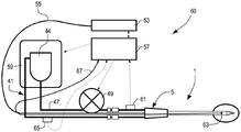
图16是使用上述实施例之一中的装置1的设备60的示意图。在图16的图解中,冷却回路41是闭合回路。由附图标记53指示的是发射激光辐射的激光源,所述激光辐射借助光纤55传送到装置1。光纤55可以通过连接器19(图1)借助连接元件5连接到装置1的光导27。光纤55可以任选地是上述光纤28的延伸部。Fig. 16 is a schematic diagram of a
由附图标记57指示的是控制单元,所述控制单元可以连接到激光源53以控制激光辐射的发射,发射到冷却回路41中的泵49,并且发射到冷却装置59以从冷却回路41去除冷却剂热量。控制单元57还可以在功能上连接到设备60中的其它传感器。例如,可以提供压力传感器61,其检测冷却回路41的输送分支中的压力,即,在泵49的下游在管47中的压力。在装置1的远侧端部处,即,优选地在外部管状结构21的内部并且与其末端端部相邻,可以定位有温度传感器63,以将由外部管状结构21形成的导管中且因此间接地在周围组织中的温度保持在控制下,在所述周围组织中已经插入有导管。在某些实施例中,还可以提供流量计65,其测量在冷却回路41中循环的冷却剂的流量。Indicated by
传感器61、63、65允许控制设备60的及与其有接口的装置1的所有操作。中央单元57和温度传感器63之间的电连接可以使用穿过连接元件5(图2)中的通道11的电缆67来获得。The
图17示出与参照图16描述的设备类似的设备60。相同的附图标记指示与已经参照图16描述的部件相同或相对应的部件。在图17的实施例中,代替用于冷却剂的罐,提供如由71指示的管,其形成热交换器并且具有足以容纳合适的量的冷却剂的总体内部容积。管71可以至少部分地位于冷却系统73内,例如,包括珀耳帖(Peltier)电池,以冷却在冷却回路中循环的冷却剂。FIG. 17 shows a
使用与装置1相关联的温度传感器可以允许监测使用该装置执行的处理。温度传感器可以向控制单元57提供信息,尤其提供关于冷却剂的温度的信息,并且因此间接地提供关于在处理期间在周围组织中发展的温度的信息。该温度取决于组织并且是其吸收系数、散射、所使用的辐射的波长、发射的功率和冷却剂的流量以及冷却剂的温度的函数。Using a temperature sensor associated with the
控制单元57可以对由源53输送的功率、冷却剂的流量以及冷却剂的温度起作用,以控制周围组织中的温度。The
温度传感器63还可以用于直接测量组织的温度。为此目的,温度传感器63足以阻止由源53发射激光辐射并且通过泵49使冷却剂循环。在几秒(4秒至5秒)内,在外部管状结构21内的冷却剂的温度达到周围组织的温度并且由温度传感器63直接测量。The
通过控制上述参数,当达到临界温度时,也能够停止由激活源53递送的功率,而同时借助泵49维持冷却剂的循环为活跃的。By controlling the above-mentioned parameters, it is also possible to stop the power delivered by the
在冷却回路41的返回分支上的流量计65和在冷却回路41的输送分支上的压力传感器61识别出与装置的正确操作不相容的流动中的异常。例如,能够检测冷却剂的任何泄漏。还能够提供两个流量计,一个流量计在输送分支上,并且一个流量计在返回分支上。The
在某些实施例中,控制单元57可以作用在冷却系统59、73上,所述冷却系统59、73调节冷却剂的温度,例如,以获得冷却剂的温度控制,从而提高组织冷却的效率。In some embodiments, the
使用的冷却剂可以是液体或气体。如上所述,就液体冷却剂而言,能够使用由水和0.9%NaCl构成的盐溶液或其它合适的浓度的盐溶液。作为气体冷却剂,可以使用氮气、二氧化碳或其它合适的气体。The coolant used can be liquid or gaseous. As mentioned above, as the liquid coolant, a saline solution consisting of water and 0.9% NaCl or other suitable concentration saline solution can be used. As gas coolant, nitrogen, carbon dioxide or other suitable gases can be used.
如上所述,光导27可以包括光纤28,所述光纤28延伸直到内部管状结构23的末端端部。光纤28可以在其末端区域中即靠近内部管状结构23和外部管状结构21的末端端部具有表面加工,所述表面加工通过由光纤28自身承载的电磁辐射的扩散而促进横向发射。在其它实施例中,光纤28可以与光学扩散器30(参见图7和图8)相关联。光学扩散器30可以具有形式或表面加工,或者光学扩散器30可以由合适的材料制成,以促进电磁辐射的横向扩散。As mentioned above, the
在尤其有利的实施例中,光学扩散器30在平面上和在彼此成直角的两个平面上具有起伏形式,例如,所述起伏形式呈现螺旋形式,如在图18图解地示出。该图仅示出内部管状结构23、光纤28的末端部分和扩散器30。扩散器30具有围绕内部管状结构23的纵向几何轴线的螺旋形延伸部。扩散器30的起伏形式促进电磁辐射向外部的传播。In a particularly advantageous embodiment, the
为了获得改进的光学扩散的分布,能够调节可以形成扩散器30的各种部件。图19、图20、图21示意性地示出包括光纤28和扩散器30的光导27的三个实施例。在所示的三个实施例中,扩散器30包括芯部30A和包围芯部30A的护套30。对于在光导27中传播的电磁辐射而言,形成扩散器30的两个元件可以是扩散的,或者一个可以是扩散的,并且另一个是透明的。在图19的实施例中,芯部30A和护套30B两者均由扩散材料制成的。在图20的实施例中,芯部30A由扩散材料制成,并且护套30B由透明材料制成。在图21的实施例中,芯部30A是透明的,并且护套30B是扩散的。图22A至图22I示出在扩散器30的各种实施例中的电磁辐射扩散的图解。图22A至图22D示出用于如图20中所示的制造的扩散器30的扩散图,即,所述扩散器30具有扩散芯部和具有直线形状的透明外部护套。针对扩散器30的不同长度,分别为15mm、20mm、25mm和30mm,获得四个图。通过增大扩散器30的长度,可以看出定向发射的损失更明显,而对径向和后向发射没有特定影响。为了改变径向发射,使用容纳在芯部30A中的不同浓度或不同粒度的扩散粉末。图22E中的图解示出由扩散芯部和扩散护套制成的且具有螺旋形状的扩散器30的发射,所述扩散器30具有单个绕组。图22F中的图解示出使用相同的扩散器获得的结果,但是具有直线形状。In order to obtain an improved distribution of optical diffusion, the various components that may form
图22G、图22H和图22I的图解示出具有透明芯部和具有以下几何特征的扩散护套的扩散器30的发射:关于图22G,扩散器20是直线的,就图22H而言,扩散器具有螺旋形发展(图18),其具有两个绕组,并且最后图22I的图解涉及具有直线截面和形成单个绕组的螺旋形截面的扩散器的发射。22G, 22H and 22I are diagrams showing the emission of a
可以注意到,图22G、图22H和图22I的辐射图解涉及具有螺旋形部分的扩散器30,其类似于借助扩散护套和扩散芯部获得的发射图(图22E、22F的图解),但是这在结构上显示出困难。在扩散器具有至少部分螺旋形状的情况下的具有透明芯部和扩散护套的实施例(图22I的图解)提供了最均匀的横向发射。It may be noted that the radiation diagrams of FIGS. 22G , 22H and 22I relate to a
扩散器30可以具有各种形状的尖端,如图23A,图23B和图23C中示意性地示出的。在图23A中,扩散器20终止于截头圆锥形或截头金字塔形的末端元件,在图23B中,提供了具有凸形半球形的末端元件的末端元件,在图23C中,末端元件具有凹形半球形形状。扩散器30的尖端的形状可以根据装置1的应用来选择,例如,以实现辐射到所处理的组织中的更大或更小地穿透。The
关于芯部和关于护套两者,扩散器可以由例如聚合物材料或石英制成。可以在构成扩散器的材料中引入射线不透性的粉末,或者可以插入尖端标记以用于具有X射线监测的应用。Both as regards the core and as regards the sheath, the diffuser may be made of, for example, a polymer material or quartz. Radiopaque powders can be incorporated into the material making up the diffuser, or tip markers can be inserted for applications with X-ray monitoring.
以上公开的各种实施例的若干特征可以以不同方式彼此结合,从而产生甚至可以没有第一间隔物和第二间隔物的装置。Several features of the various embodiments disclosed above may be combined with each other in different ways to create a device that may even be free of the first and second spacers.
Claims (12)
Applications Claiming Priority (3)
| Application Number | Priority Date | Filing Date | Title |
|---|---|---|---|
| IT102016000113583 | 2016-11-10 | ||
| IT102016000113583A IT201600113583A1 (en) | 2016-11-10 | 2016-11-10 | LASER THERMO-WELDING DEVICE WITH A DIFFUSER CATHETER AND EQUIPMENT INCLUDING THE DEVICE |
| PCT/EP2017/078233 WO2018087014A1 (en) | 2016-11-10 | 2017-11-03 | Device for laser thermal ablation with a diffusing catheter and equipment comprising said device |
Publications (2)
| Publication Number | Publication Date |
|---|---|
| CN110114030A CN110114030A (en) | 2019-08-09 |
| CN110114030B true CN110114030B (en) | 2022-11-15 |
Family
ID=58228447
Family Applications (1)
| Application Number | Title | Priority Date | Filing Date |
|---|---|---|---|
| CN201780080371.7A Active CN110114030B (en) | 2016-11-10 | 2017-11-03 | Device for laser thermal ablation by means of a diffusion catheter and apparatus comprising such a device |
Country Status (5)
| Country | Link |
|---|---|
| US (1) | US11331145B2 (en) |
| EP (1) | EP3538004B1 (en) |
| CN (1) | CN110114030B (en) |
| IT (1) | IT201600113583A1 (en) |
| WO (1) | WO2018087014A1 (en) |
Families Citing this family (13)
| Publication number | Priority date | Publication date | Assignee | Title |
|---|---|---|---|---|
| WO2019234623A1 (en) | 2018-06-05 | 2019-12-12 | Elesta S.R.L. | Optical fiber device for laser thermal ablation and thermal therapy |
| CN109946786A (en) * | 2019-03-25 | 2019-06-28 | 北京大学口腔医学院 | A kind of the multifunction laser scalpel and laser process equipment of controllable self-deformation optical fiber |
| US12402946B2 (en) | 2019-06-19 | 2025-09-02 | Boston Scientific Scimed, Inc. | Breakdown of laser pulse energy for breakup of vascular calcium |
| US12280223B2 (en) * | 2019-06-26 | 2025-04-22 | Boston Scientific Scimed, Inc. | Focusing element for plasma system to disrupt vascular lesions |
| AU2019458295B2 (en) | 2019-07-24 | 2025-02-27 | Medlogical Innovations Pty Ltd | System with cooling fluid for interstitial laser therapy |
| US12102384B2 (en) | 2019-11-13 | 2024-10-01 | Bolt Medical, Inc. | Dynamic intravascular lithotripsy device with movable energy guide |
| US12274497B2 (en) | 2019-12-18 | 2025-04-15 | Bolt Medical, Inc. | Multiplexer for laser-driven intravascular lithotripsy device |
| US12446961B2 (en) | 2020-02-10 | 2025-10-21 | Bolt Medical, Inc. | System and method for pressure monitoring within a catheter system |
| US12295654B2 (en) | 2020-06-03 | 2025-05-13 | Boston Scientific Scimed, Inc. | System and method for maintaining balloon integrity within intravascular lithotripsy device with plasma generator |
| US12016610B2 (en) | 2020-12-11 | 2024-06-25 | Bolt Medical, Inc. | Catheter system for valvuloplasty procedure |
| WO2022154954A1 (en) | 2021-01-12 | 2022-07-21 | Bolt Medical, Inc. | Balloon assembly for valvuloplasty catheter system |
| US11839391B2 (en) | 2021-12-14 | 2023-12-12 | Bolt Medical, Inc. | Optical emitter housing assembly for intravascular lithotripsy device |
| US12533184B2 (en) | 2022-04-02 | 2026-01-27 | Boston Scientific Scimed, Inc. | Optical connector assembly for intravascular lithotripsy device |
Family Cites Families (11)
| Publication number | Priority date | Publication date | Assignee | Title |
|---|---|---|---|---|
| US5042980A (en) | 1989-05-26 | 1991-08-27 | C. R. Bard, Inc. | Optical fiber diffusion tip for uniform illumination |
| DE3941705C2 (en) * | 1989-12-18 | 1994-10-13 | Gsf Forschungszentrum Umwelt | Device for the isotropic irradiation of cavities of spherical shape |
| JP3551996B2 (en) * | 1995-08-25 | 2004-08-11 | 松下電器産業株式会社 | Medical laser probe |
| EP1072231B1 (en) * | 1999-07-30 | 2005-12-28 | Terumo Kabushiki Kaisha | Laser irradiation apparatus |
| US7214223B2 (en) * | 2000-03-24 | 2007-05-08 | Boston Scientific Scimed, Inc. | Photoatherolytic catheter apparatus and method |
| DE10063029A1 (en) * | 2000-12-18 | 2002-07-04 | Dornier Medtech Holding Int Gmbh | Laser surgical applicator and method for its manufacture |
| US7270656B2 (en) * | 2003-11-07 | 2007-09-18 | Visualase, Inc. | Cooled laser fiber for improved thermal therapy |
| US20070282404A1 (en) * | 2006-04-10 | 2007-12-06 | University Of Rochester | Side-firing linear optic array for interstitial optical therapy and monitoring using compact helical geometry |
| EP2150194B1 (en) | 2007-04-27 | 2012-09-12 | Tyco Healthcare Group LP | System for treating hollow anatomical structures |
| US9283040B2 (en) * | 2013-03-13 | 2016-03-15 | The Spectranetics Corporation | Device and method of ablative cutting with helical tip |
| US10631930B1 (en) * | 2013-10-15 | 2020-04-28 | Nipro Corporation | Ablation system and ablation device |
-
2016
- 2016-11-10 IT IT102016000113583A patent/IT201600113583A1/en unknown
-
2017
- 2017-11-03 US US16/348,656 patent/US11331145B2/en active Active
- 2017-11-03 WO PCT/EP2017/078233 patent/WO2018087014A1/en not_active Ceased
- 2017-11-03 CN CN201780080371.7A patent/CN110114030B/en active Active
- 2017-11-03 EP EP17792094.9A patent/EP3538004B1/en active Active
Also Published As
| Publication number | Publication date |
|---|---|
| CN110114030A (en) | 2019-08-09 |
| EP3538004A1 (en) | 2019-09-18 |
| WO2018087014A1 (en) | 2018-05-17 |
| US20190321101A1 (en) | 2019-10-24 |
| EP3538004B1 (en) | 2021-06-23 |
| IT201600113583A1 (en) | 2018-05-10 |
| US11331145B2 (en) | 2022-05-17 |
Similar Documents
| Publication | Publication Date | Title |
|---|---|---|
| CN110114030B (en) | Device for laser thermal ablation by means of a diffusion catheter and apparatus comprising such a device | |
| CN110446472B (en) | Device for laser thermal ablation by means of a centering device and device comprising the device | |
| JP3675482B2 (en) | Phototherapy equipment | |
| EP0582686B1 (en) | Apparatus using a laser lucent needle | |
| CN110139618B (en) | Apparatus for laser thermal ablation with the aid of a helical diffuser and apparatus comprising the same | |
| US5957917A (en) | Transluminal hyperthermia catheter and method for use | |
| CN110290757A (en) | Device for ablation therapy and method of use | |
| CN111050682A (en) | Non-ablative photonic devices and related methods | |
| CN112399871B (en) | Fiber optic apparatus for laser thermal ablation and hyperthermia | |
| US10018784B2 (en) | Fiber-optic device and process for manufacturing the device | |
| WO2018087012A1 (en) | Device for laser thermal ablation and apparatus comprising said device | |
| RU2741236C1 (en) | Light guide instrument with microfocusing | |
| JP5001363B2 (en) | An ablation device that cauterizes biological tissue such as tumorous tissue locally by heat. | |
| EP1527798A2 (en) | Diffusive tip assembly | |
| Russo et al. | Optical fibres for medical applications: output beam shaping | |
| RUSSO | SHI./I69-20 | |
| JPS62292158A (en) | Laser heating apparatus |
Legal Events
| Date | Code | Title | Description |
|---|---|---|---|
| PB01 | Publication | ||
| PB01 | Publication | ||
| SE01 | Entry into force of request for substantive examination | ||
| SE01 | Entry into force of request for substantive examination | ||
| GR01 | Patent grant | ||
| GR01 | Patent grant |