CN110109162B - GNSS receiver self-adaptive Kalman filtering positioning resolving method - Google Patents
GNSS receiver self-adaptive Kalman filtering positioning resolving method Download PDFInfo
- Publication number
- CN110109162B CN110109162B CN201910233530.3A CN201910233530A CN110109162B CN 110109162 B CN110109162 B CN 110109162B CN 201910233530 A CN201910233530 A CN 201910233530A CN 110109162 B CN110109162 B CN 110109162B
- Authority
- CN
- China
- Prior art keywords
- receiver
- value
- representing
- covariance matrix
- matrix
- Prior art date
- Legal status (The legal status is an assumption and is not a legal conclusion. Google has not performed a legal analysis and makes no representation as to the accuracy of the status listed.)
- Active
Links
- 238000001914 filtration Methods 0.000 title claims abstract description 46
- 238000000034 method Methods 0.000 title claims abstract description 41
- 238000005259 measurement Methods 0.000 claims abstract description 38
- 239000011159 matrix material Substances 0.000 claims description 65
- 230000008569 process Effects 0.000 claims description 19
- 239000013598 vector Substances 0.000 claims description 18
- 230000003595 spectral effect Effects 0.000 claims description 9
- 230000003044 adaptive effect Effects 0.000 claims description 8
- 230000007704 transition Effects 0.000 claims description 8
- 230000008859 change Effects 0.000 claims description 6
- 238000004422 calculation algorithm Methods 0.000 abstract description 18
- 238000012545 processing Methods 0.000 abstract description 2
- 230000003068 static effect Effects 0.000 description 9
- 238000010586 diagram Methods 0.000 description 6
- 238000012360 testing method Methods 0.000 description 4
- 230000000694 effects Effects 0.000 description 3
- 238000004088 simulation Methods 0.000 description 3
- 230000008901 benefit Effects 0.000 description 2
- 238000004364 calculation method Methods 0.000 description 2
- 238000004458 analytical method Methods 0.000 description 1
- 230000009286 beneficial effect Effects 0.000 description 1
- 238000012937 correction Methods 0.000 description 1
- 230000007812 deficiency Effects 0.000 description 1
- 238000005516 engineering process Methods 0.000 description 1
- 230000006872 improvement Effects 0.000 description 1
- 238000012886 linear function Methods 0.000 description 1
- 230000004807 localization Effects 0.000 description 1
- 238000013507 mapping Methods 0.000 description 1
- 230000004048 modification Effects 0.000 description 1
- 238000012986 modification Methods 0.000 description 1
- 238000005070 sampling Methods 0.000 description 1
Images


Classifications
-
- G—PHYSICS
- G01—MEASURING; TESTING
- G01S—RADIO DIRECTION-FINDING; RADIO NAVIGATION; DETERMINING DISTANCE OR VELOCITY BY USE OF RADIO WAVES; LOCATING OR PRESENCE-DETECTING BY USE OF THE REFLECTION OR RERADIATION OF RADIO WAVES; ANALOGOUS ARRANGEMENTS USING OTHER WAVES
- G01S19/00—Satellite radio beacon positioning systems; Determining position, velocity or attitude using signals transmitted by such systems
- G01S19/38—Determining a navigation solution using signals transmitted by a satellite radio beacon positioning system
- G01S19/39—Determining a navigation solution using signals transmitted by a satellite radio beacon positioning system the satellite radio beacon positioning system transmitting time-stamped messages, e.g. GPS [Global Positioning System], GLONASS [Global Orbiting Navigation Satellite System] or GALILEO
- G01S19/42—Determining position
Landscapes
- Engineering & Computer Science (AREA)
- Radar, Positioning & Navigation (AREA)
- Remote Sensing (AREA)
- Computer Networks & Wireless Communication (AREA)
- Physics & Mathematics (AREA)
- General Physics & Mathematics (AREA)
- Position Fixing By Use Of Radio Waves (AREA)
- Navigation (AREA)
Abstract
The invention discloses a GNSS receiver self-adaptive Kalman filtering positioning resolving method, which adopts a self-adaptive Kalman filtering algorithm to perform positioning resolving according to the fact that a GNSS receiver receives baseband signal processing and outputs GNSS measured values. The self-adaptive Kalman filtering algorithm carries out real-time estimation on the system noise covariance and the measurement noise covariance according to the innovation quantity or the residual quantity on the basis of the conventional Kalman filtering algorithm, so that the receiver outputs a smoother and more accurate positioning result.
Description
Technical Field
The invention belongs to the technical field of satellite navigation, and particularly relates to a GNSS receiver self-adaptive Kalman filtering positioning resolving method which can improve the positioning precision of a vehicle-mounted navigation system.
Background
The GNSS positioning calculation algorithm is one of the key technologies to reduce the positioning accuracy error. The least square algorithm has been widely used for a long time with the advantages of its simple principle, etc., and its principle is to seek an optimal point between the error of each measurement value and its noise, so as to minimize the residual square sum of all measurement quantities, but because different measurement errors and noises at different times are converted into corresponding different positioning errors and noises after the least square calculation, the positioning result of the least square is rough and cluttered. In order to overcome the performance deficiency of least squares, a nonlinear filtering algorithm is introduced into the navigation field.
The nonlinear Kalman filtering algorithm generally comprises extended Kalman filtering and linearized Kalman filteringTwo forms. The basic idea of the extended kalman filtering is to assume that the estimated value of the current system state by the kalman filtering is very close to the true value, so that taylor expansion is performed on the nonlinear functions f and h at the estimated value of the current state and linearization is realized. The linear kalman filtering and the extended kalman filtering are mainly different in that: the former puts the nonlinear functions f and h in the filter pair current system state xkBecause the actual operating state x of the nonlinear system is known in advancekApproximately according to the desired trajectory xk, so that these non-linear functions are at xkThe value of a point can be expressed as being at xkTaylor expansion, thereby completing the linearization. Therefore, the linear kalman filter needs to know the operation track of the system state in advance, and this condition is unpredictable for the positioning navigation system, so the extended kalman filter is widely used. In order to reduce the real-time calculation amount of the system, the extended Kalman adopts a first-order Taylor series expansion linearization method to generate model errors, so that the filtering performance is reduced, and even the filter is diverged. Extended kalman filtering often fails to give optimal estimates due to the difficulty in adjusting the relevant filter parameters.
Disclosure of Invention
Aiming at the problem of large positioning error caused by unknown vehicle-mounted motion models and noise statistical characteristics in a GNSS navigation system, the application provides a receiver self-adaptive Kalman filtering positioning resolving method, and parameters are automatically predicted and adjusted through a set model, so that the receiver outputs a smoother and more accurate positioning result.
The invention is realized by the following technical scheme:
a GNSS receiver self-adaptive Kalman filtering positioning resolving method comprises the following steps;
s1, establishing a receiver state equation based on the GNSS positioning system, and setting a state variable X of the state equation;
X=[x,y,z,vx,vy,vz,δfu,δtu]
wherein x, y, z represent the corresponding seats of the receiverLocation information of the target system; v. ofx,vy,vzVelocity information respectively representing corresponding coordinates of the receiver; δ fuRepresenting a clock offset drift frequency of the receiver; δ tuRepresenting the clock difference of the receiver;
s2, establishing a system model for describing the motion state of the carrier receiver, wherein the expression of the system model is as follows;
xk=Axk-1+qk
wherein A represents the state transition matrix of the state variables, qkMeans representing a process noise vector;
s3, establishing a measurement equation y (n) of the receiver based on the GNSS positioning system;

ρ(n)the pseudo range from a receiver to an nth satellite at a certain observation time is represented by the following formula;

n is a satellite number participating in positioning; r is(n)Represents the geometric distance of the receiver from the satellite n; δ tuRepresenting the receiver clock error; δ t(n)Representing the satellite clock error; iono(n)Representing the corresponding satellite ionospheric delay; t is(n)Representing the corresponding satellite tropospheric delay; representing the pseudo-range measurement noise amount;


I(n)represents a unit observation vector of the nth satellite at the receiver;
v is the velocity of the receiver; δ fuA clock drift for the receiver; v(n)The speed of the nth satellite; δ f(n)Clock drift for the nth satellite; measuring a noise amount for the pseudo-range rate of change;
s4, measurement equation y for step S3(n)Solving to obtain an initial filter value at the initial 0 moment, wherein the initial filter value comprises an optimal estimation value X0And the posteriori estimated error covariance matrix P at the starting 0 time0;
S5, carrying out self-adaptive filtering on the system model in the step 2 according to the initial filtering value at the time 0 obtained in the step S4 to obtain the prior estimated value at the kth epoch Sum prior estimation error covariance matrix


Wherein, representing the process noise vector w at the kth epoch timekIs determined by the mean value of the average of the values,
 an estimate representing the covariance matrix of the noise during the kth epoch time, and
 and
and updating in real time, wherein A represents a state transition matrix of a state variable;
s6, comparing the prior estimated value obtained in step 5 Sum prior estimation error covariance matrix
 Calculating to obtain a measurement relation matrix C at the kth epochkGain matrix KkOptimal value of (e) and innovation sequence ek;


Wherein, representing the estimated value of the measurement noise covariance matrix at the kth epoch moment, and updating the estimated value in real time; ck TIs CkThe transposed matrix of (2);


wherein, ykA system observation for the kth epoch; for measuring noise vectors vkIs on the average value of
 Updating in real time;
s7, obtaining a measurement relation matrix C according to the step 6kGain matrix KkOptimal value of (e) and innovation sequence ekCalculating to obtain the optimal estimated value X at the k epochkSum a posteriori estimation error covariance matrix As the initial input value of the filter at the k +1 th epoch;


preferably, in step S4, a weighted least square method is used to calculate the measurement equation to obtain an optimal estimation value X of the receiver state variable X at the starting 0 moment0And the posteriori estimated error covariance matrix P at the starting 0 time0;


Wherein, varposTo measure the mean square error of the pseudorange, varvelIs the mean square error of the doppler velocity measurement.
Preferably, the process noise vector w in step S5kMean value q ofkThe initial value is 0, and the updating method is as the following formula;

wherein, XjN represents the length of the sliding window width, and the physical meaning of N represents the number of selected filtering times;
process noise covariance matrix The initial values of (a) are as follows:

wherein (S)vx,Sυy,Svz) Power spectral density of receiver velocity; sfPower spectral density of clock drift, StThe power spectral density of the clock;
taking the covariance matrix of the alpha filtering pair process noise according to the sum of the squares of the residual errors of the N-1 times and the squares of the residual errors of the N times Updating, wherein an updating formula is as follows;


wherein, Δ XjFor two adjacent calendarsSequence of state quantities of elements, ATA transpose matrix representing a state transition matrix.
Preferably, the noise covariance matrix is measured in step S6 Is a theoretical measurement noise vector vkMean of, measure noise covariance matrix
 The updating method is as follows;

preferably, the noise covariance matrix is measured in step S6 The initial values of (a) are set as:

measuring a noise covariance matrix The update formula is as follows;

wherein e isjIs the innovation sequence of the jth epoch.
Compared with the prior art, the invention has the following beneficial technical effects:
the invention provides a GNSS receiver self-adaptive Kalman filtering positioning resolving method. Secondly, the innovation sequence is used as a self-adaptive factor, so that the error between the estimated value and the measured value can be calculated more accurately, the measurement noise and the process noise matrix can be corrected more accurately, and the problem of positioning error of a system model caused by noise is reduced; compared with the existing positioning resolving method, the method has the advantage that the positioning accuracy is better improved aiming at the motion model and the noise statistical characteristic of the GNSS vehicle navigation system.
Drawings
FIG. 1 is a flow chart of a Kalman filtering algorithm for GNSS positioning according to the present invention;
FIG. 2 is a block diagram of a simulation platform;
FIG. 3 is an east position error comparison plot in a static scene;
FIG. 4 is a comparison graph of north position errors in a static scenario;
FIG. 5 is a diagram of comparing zenith errors in a static scene;
FIG. 6 is a diagram comparing east velocity errors in a static scene;
FIG. 7 is a comparison graph of northbound speed error in a static scenario;
FIG. 8 is a chart comparing zenith velocity errors in a static scene;
FIG. 9 is an east position error comparison plot in a dynamic scene;
FIG. 10 is a north position error comparison plot in a dynamic scenario;
FIG. 11 is a diagram of comparing zenith position errors in a dynamic scene;
FIG. 12 is a diagram comparing east speed error in a dynamic scene;
FIG. 13 is a comparison graph of north velocity errors in a dynamic scenario;
FIG. 14 is a diagram of comparing zenith velocity errors in a dynamic scene.
Detailed Description
The present invention will now be described in further detail with reference to the attached drawings, which are illustrative, but not limiting, of the present invention.
A GNSS receiver self-adaptive Kalman filtering positioning resolving method comprises the steps of processing a baseband signal received by the GNSS receiver and outputting a GNSS measured value, and performing positioning resolving by adopting a self-adaptive Kalman filtering algorithm. The self-adaptive Kalman filtering algorithm carries out real-time estimation on the system noise covariance and the measurement noise covariance according to the innovation quantity or the residual quantity on the basis of the conventional Kalman filtering algorithm, so that the receiver outputs a smoother and more accurate positioning result.
A GNSS receiver self-adaptive Kalman filtering positioning resolving method specifically comprises the following steps;
building system
S1, establishing a receiver state quantity equation based on the GNSS positioning system, and setting X as a state variable of the state equation;
X=[x,y,z,vx,vy,vz,δfu,δtu]
wherein x, y and z represent position information of a coordinate system corresponding to the receiver; vx, vy and vz respectively represent the speed information of the corresponding coordinates of the receiver; δ fuRepresenting a clock offset drift frequency of the receiver; δ tuRepresenting the clock difference of the receiver.
S2, establishing a system model for describing the motion state of the carrier receiver, wherein the expression of the system model is as follows;
xk=Axk-1+qk
wherein A represents the state transition matrix of the state variables, qkRepresenting the mean of the process noise vector.
S3, establishing a measurement equation y of the receiver based on the GNSS positioning system(n);

The measurement equation comprises a pseudo-range observation equation and a Doppler constant velocity equation, wherein the pseudo-range observation equation is rho(n)The state quantity corresponding to the position coordinates of the receiver is [ x, y, z, δ t ] as followsu];

N is a satellite number participating in positioning;
ρ(n)means for determining a pseudorange between the receiver and the nth satellite at a particular observation time;
δturepresenting the receiver clock error; δ t(n)Representing the satellite clock error; iono(n)Representing the corresponding satellite ionospheric delay; t is(n)Representing the corresponding satellite tropospheric delay; the pseudorange measures the amount of noise.
r(n)Representing the geometric distance of the receiver from the satellite n, the formula is as follows:

(x(n),y(n),z(n)) Corresponding to the three-dimensional coordinates under the positioning system for the nth satellite; (x, y, z) is the coordinate of the coordinate system corresponding to the receiver;


Wherein, I(n)Represents a unit observation vector of the nth satellite at the receiver;
v denotes the unknown receiver velocity;
δfuindicating an unknown receiver clock drift;
V(n)representing the velocity of the nth satellite;
δf(n)indicating the clock frequency drift of the nth satellite;

pseudorange and doppler measurement noise volume
The covariance matrix of the measurement noise, R ═ E (ε -T)。
S4, selection of 0 moment initial value of Kalman filter
To the measurement equation y according to a weighted least squares method(n)Resolving to obtain initial filter value at initial 0 moment, which comprises optimal estimated value X of state variable X of receiver0And the posteriori estimated error covariance matrix P at the starting 0 time0;


Wherein, varposTo measure the mean square error of the pseudorange, varvelIs the mean square error of the doppler velocity measurement.
S5, filtering the system model in the step 2 according to the initial filtering value at the time 0 obtained in the step S4 to obtain the prior estimation value at the kth epoch Sum prior estimation error covariance matrix


Wherein, representing the process noise vector w at the kth epoch timekIs initially taken to be 0, and is summed to the path noise vector wkMean value of
 Updating in real time;


wherein (S)vx,Svy,Svz) Power spectral density of receiver velocity; sfPower spectral density of clock drift, StThe power spectral density of the clock;
according to the square sum of the residual errors of the first N-1 times and the square of the residual errors of the N times, the estimation value of the alpha filtering to the process noise covariance matrix is obtained Updating is carried out, wherein N represents the length of the sliding window width, the physical meaning represents the selected filtering times, and the filtering times can be properly adjusted according to the length of the epoch time.
Process noise vector wkMean value estimate of Sum process noise covariance matrix estimate
 The update formula of (2) is as follows:


wherein A isTIs a transposed matrix of the state transition matrix a; the optimal estimation value corresponding to the jth epoch moment is obtained; Δ XjCan correct the state quantity residual error sequence of two adjacent epochs in real time
 And the matrix achieves the effect of self-adaption.
S6, obtaining the prior estimated value according to the step S5 Calculating to obtain a measurement relation matrix C at the kth epochkSee formula (6):

the prior estimation error covariance matrix obtained in step S5 And a measurement relation matrix CkCalculating the gain matrix K of the K epochkSee equation (7) for details of the optimal value of (d);

wherein a noise covariance matrix is measured Is set to
 And for the measurement noise covariance matrix
 Updating, wherein an updating formula is as follows;

wherein e isjMeaning the innovation sequence of the jth epoch.
A priori estimated value obtained according to step S5 Calculating an innovation sequence ekSee formula (9) for details;


wherein, ykRepresents a system observation for the kth epoch; is a theoretical measurementNoise vector vkIs on the average value of
 Updating in real time, wherein the updating formula is as follows:

innovation sequence ekIs the core of the adaptive filtering of the invention, and can carry out real-time noise covariance matrix QkAnd measure the noise covariance matrix RkReal-time estimation is performed.
S7, gain matrix K obtained according to the step S6kAnd an innovation sequence ekAnd obtaining the filter output value at the k epoch according to the formulas (11) and (12) as the optimal estimation value at the k +1 epoch.


Compared with the prior art, the adaptive filtering provided by the invention can better improve the positioning accuracy aiming at the motion model and the noise statistical characteristic of the GNSS vehicle navigation system. Firstly, updating a residual error sequence in real time by utilizing an estimated value of adjacent time, and adjusting the residual error sequence in real time as a key correction value of process noise. Second, the innovation sequence ekAs the adaptive factor, the error between the estimated value and the measured value can be calculated more accurately, the measurement noise and the process noise matrix can be corrected more accurately, and the problem of positioning error of a system model caused by noise is reduced. FIG. 1 is a schematic flow chart of the adaptive Kalman filtering of the present invention.
The effect of the present invention can be further illustrated by the following simulation results:
test scenario
The platform of the simulation data is set up as shown in fig. 2, the test scene data comes from an Agilent signal generator, the sampling interval is 50ms, and the total observation time is 45 min. The test mainly aims at the comparison analysis of a least square algorithm, extended Kalman filtering and the adaptive Kalman filtering algorithm of the invention aiming at the positioning precision. Two sets of test scenarios: static scenes and dynamic scenes.
The first row in FIGS. 3-14 represents the location result of WLS (weighted least squares algorithm) versus the theoretical difference of the signal generator;
the second row represents the positioning result of the EKF (extended kalman filter algorithm) and the theoretical difference of the signal generator;
the third row represents the difference between the positioning result of AKF (adaptive Filter algorithm of the invention) and the theoretical coordinate of the signal generator;
the fourth row shows the mapping of the WLS, EKF and AKF localization results against the signal generator theoretical coordinate differences.
The horizontal axis of each row in fig. 3-14 represents the UTC time axis and the vertical axis represents the difference in receiver station coordinates from the reference coordinates of the signal generator.
Static scene:
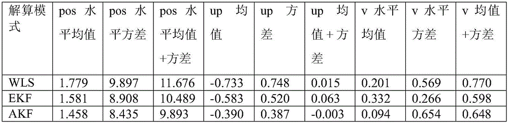
fig. 3 to 8 show the difference between the receiver station centre coordinates and the signal generator reference coordinates, fig. 3, 4 and 5 show the difference between the east, north and zenith directions of the position coordinates, respectively, and fig. 6, 7 and 8 show the difference between the east, north and zenith directions of the receiver velocity, respectively. It can be clearly seen from the figure that the algorithm of the present invention is smoother in positioning error and less in floating, so that the positioning position and speed are obviously improved in precision, which is detailed in the numerical statistical results in table 1.
The horizontal direction in this specification is the square and root of east and north.
 Wherein Δ Ni、ΔEi、ΔHiRespectively representing the N (north), E (east) and horizontal directions of the positioning dataDirectional positioning error.
TABLE 1 static scene position and velocity error comparison

Dynamic scene:
fig. 9 to 14 show the difference between the receiver station center coordinates and the reference coordinates of the signal generator, fig. 9, 10 and 11 show the difference between the east, north and zenith directions of the position coordinates, respectively, and fig. 12, 13 and 14 show the difference between the east, north and zenith directions of the receiver velocity, respectively. It can be clearly seen from the figure that the algorithm of the present invention has a significant improvement in positioning accuracy, which is detailed in the numerical statistics in table 2.
TABLE 2 dynamic scene position and velocity error comparison
The above-mentioned contents are only for illustrating the technical idea of the present invention, and the protection scope of the present invention is not limited thereby, and any modification made on the basis of the technical idea of the present invention falls within the protection scope of the claims of the present invention.
Claims (3)
1. A GNSS receiver self-adaptive Kalman filtering positioning resolving method is characterized by comprising the following steps;
s1, establishing a receiver state equation based on the GNSS positioning system, and setting a state variable X of the state equation;
X=[x,y,z,vx,vy,vz,δfu,δtu]
wherein x, y and z represent position information of a coordinate system corresponding to the receiver; vx, vy and vz respectively represent the speed information of the corresponding coordinates of the receiver; δ fuRepresenting a clock offset drift frequency of the receiver; δ tuRepresenting the clock difference of the receiver;
s2, establishing a system model for describing the motion state of the carrier receiver, wherein the expression of the system model is as follows;
xk=Axk-1+qk
wherein A represents the state transition matrix of the state variables, qkMeans representing a process noise vector;
s3, establishing a measurement equation y of the receiver based on the GNSS positioning system(n);

ρ(n)The pseudo range from a receiver to an nth satellite at a certain observation time is represented by the following formula;

n is a satellite number participating in positioning; r is(n)Represents the geometric distance of the receiver from the satellite n; δ tuRepresenting the receiver clock error; δ t(n)Representing the satellite clock error; iono(n)Representing the corresponding satellite ionospheric delay; t is(n)Representing the corresponding satellite tropospheric delay; representing the pseudo-range measurement noise amount;


I(n)represents a unit observation vector of the nth satellite at the receiver;
v is the velocity of the receiver; δ fuA clock drift for the receiver; v(n)The speed of the nth satellite; δ f(n)Clock drift for the nth satellite; measuring a noise amount for the pseudo-range rate of change;
s4, measurement equation y for step S3(n)Solving to obtain an initial filter value at the initial 0 moment, wherein the initial filter value comprises an optimal estimation value X0And the covariance matrix P of the A posteriori estimation errors at the starting 0 moment0;
S5, carrying out self-adaptive filtering on the system model in the step 2 according to the initial filtering value at the time 0 obtained in the step S4 to obtain the prior estimated value at the kth epoch Sum prior estimation error covariance matrix


Wherein, representing the process noise vector w at the kth epoch timekIs determined by the mean value of the average of the values,
 an estimate representing the covariance matrix of the noise during the kth epoch time, and
 and
and updating in real time, wherein A represents a state transition matrix of a state variable;
s6, comparing the prior estimated value obtained in step 5 Sum prior estimation error covariance matrix
 Calculating to obtain a measurement relation matrix C at the kth epochkGain matrix KkOptimal value of (e) and innovation sequence ek;


Wherein, representing the estimated value of the measurement noise covariance matrix at the kth epoch moment, and updating the estimated value in real time; ck TIs CkThe transposed matrix of (2);
measuring a noise covariance matrix The initial values of (a) are set as:

measuring a noise covariance matrix The update formula is as follows;

wherein e isjAn innovation sequence for the jth epoch;


wherein, ykA system observation for the kth epoch; for measuring noise vectors vkIs on the average value of
 Updating in real time;
measuring a noise covariance matrix Is a theoretical measurement noise vector vkMean of, measure noise covariance matrix
 The updating method is as followsFormula (I);

s7, obtaining a measurement relation matrix C according to the step 6kGain matrix KkOptimal value of (e) and innovation sequence ekCalculating to obtain the optimal estimated value X at the k epochkSum a posteriori estimation error covariance matrix As the initial input value of the filter at the k +1 th epoch;


2. the GNSS receiver adaptive Kalman filtering positioning solution method according to claim 1, characterized in that in step S4, a weighted least square method is adopted to calculate the measurement equation to obtain the optimal estimation value X of the receiver state variable X at the initial 0 moment0And the posteriori estimated error covariance matrix P at the starting 0 time0;


Wherein, varposTo measure the mean square error of the pseudorange, varvelMean square error for Doppler velocity measurement。
3. The GNSS receiver adaptive Kalman filtering positioning solution method according to claim 2, characterized in that in step S5, the process noise vector wkMean value q ofkThe initial value is 0, and the updating method is as the following formula;

wherein, XjN represents the length of the sliding window width, and the physical meaning of N represents the number of selected filtering times;
process noise covariance matrix The initial values of (a) are as follows:

wherein (S)vx,Svy,Svz) Power spectral density of receiver velocity; sfPower spectral density of clock drift, StThe power spectral density of the clock;
taking the covariance matrix of the alpha filtering pair process noise according to the sum of the squares of the residual errors of the N-1 times and the squares of the residual errors of the N times Updating, wherein an updating formula is as follows;


wherein, Delta XjIs a state quantity residual error sequence of two adjacent epochs, ATA transpose matrix representing a state transition matrix.
Priority Applications (1)
| Application Number | Priority Date | Filing Date | Title |
|---|---|---|---|
| CN201910233530.3A CN110109162B (en) | 2019-03-26 | 2019-03-26 | GNSS receiver self-adaptive Kalman filtering positioning resolving method |
Applications Claiming Priority (1)
| Application Number | Priority Date | Filing Date | Title |
|---|---|---|---|
| CN201910233530.3A CN110109162B (en) | 2019-03-26 | 2019-03-26 | GNSS receiver self-adaptive Kalman filtering positioning resolving method |
Publications (2)
| Publication Number | Publication Date |
|---|---|
| CN110109162A CN110109162A (en) | 2019-08-09 |
| CN110109162B true CN110109162B (en) | 2021-06-11 |
Family
ID=67484662
Family Applications (1)
| Application Number | Title | Priority Date | Filing Date |
|---|---|---|---|
| CN201910233530.3A Active CN110109162B (en) | 2019-03-26 | 2019-03-26 | GNSS receiver self-adaptive Kalman filtering positioning resolving method |
Country Status (1)
| Country | Link |
|---|---|
| CN (1) | CN110109162B (en) |
Families Citing this family (15)
| Publication number | Priority date | Publication date | Assignee | Title |
|---|---|---|---|---|
| CN110632629B (en) * | 2019-09-17 | 2023-12-08 | 成都国星通信有限公司 | Self-adaptive Kalman filtering method suitable for high-dynamic non-stationary system |
| CN112684481B (en) * | 2019-10-18 | 2022-10-11 | 千寻位置网络有限公司 | Positioning calculation method and device and storage medium |
| CN110850450A (en) * | 2019-12-03 | 2020-02-28 | 航天恒星科技有限公司 | Adaptive estimation method for satellite clock error parameters |
| CN111367160B (en) * | 2020-03-30 | 2021-07-06 | 武汉大学 | A GNSS timing receiver precision clock control method and system |
| CN111323793B (en) * | 2020-03-30 | 2021-02-05 | 中国矿业大学 | GNSS pseudo-range single-point positioning state domain integrity monitoring method |
| CN111855219A (en) * | 2020-07-20 | 2020-10-30 | 哈尔滨工程大学 | A method for predicting security parameters of diesel engine lubricating oil entering the engine based on grey theory |
| CN111736183B (en) * | 2020-07-28 | 2023-12-05 | 中国人民解放军战略支援部队信息工程大学 | A precision single-point positioning method and device combining BDS2/BDS3 |
| CN114252892A (en) * | 2020-09-10 | 2022-03-29 | 阿里巴巴集团控股有限公司 | Training method of machine learning model, interference detection method and device |
| CN112325882B (en) * | 2020-10-14 | 2023-03-10 | 南京航空航天大学 | Protection level calculation method for Kalman filtering innovation chi-square detection technology |
| CN112660144B (en) * | 2020-12-04 | 2022-06-24 | 上汽通用五菱汽车股份有限公司 | Yaw rate filtering method, control terminal, vehicle and storage medium |
| CN113109848B (en) * | 2021-04-14 | 2023-03-14 | 长沙学院 | Navigation positioning method under low-speed rotation condition of carrier |
| CN113204038B (en) * | 2021-04-16 | 2023-03-21 | 北方工业大学 | Kalman smoothing filtering method and smoothing filter based on time domain and frequency domain |
| CN114488227B (en) * | 2022-01-26 | 2023-10-20 | 西南交通大学 | Multipath error correction method based on spatial correlation |
| CN116009041B (en) * | 2023-03-27 | 2023-06-09 | 太原理工大学 | Robust self-adaptive GNSS high-precision positioning method based on chi-square test |
| CN116165690B (en) * | 2023-04-21 | 2023-07-07 | 山西省娄烦县皇姑山矿业有限责任公司 | GNSS/INS-based double-adaptive-factor combined navigation positioning method |
Citations (9)
| Publication number | Priority date | Publication date | Assignee | Title |
|---|---|---|---|---|
| CN102269819A (en) * | 2010-06-03 | 2011-12-07 | 武汉大学 | Estimation method for precise point positioning (PPP) method |
| US8525727B2 (en) * | 2009-12-29 | 2013-09-03 | Texas Instruments Incorporated | Position and velocity uncertainty metrics in GNSS receivers |
| CN104411013A (en) * | 2014-11-14 | 2015-03-11 | 苏州英菲泰尔电子科技有限公司 | GTS (Guaranteed Time Slot) allocation management method and equipment |
| CN108153259A (en) * | 2017-12-21 | 2018-06-12 | 北京工业大学 | A kind of multi-controller optimal State Estimation control strategy design method based on Kalman filtering |
| CN108717174A (en) * | 2018-04-03 | 2018-10-30 | 杭州电子科技大学 | The quick covariance of prediction based on information theory interacts combining passive co-located method |
| CN109000642A (en) * | 2018-05-25 | 2018-12-14 | 哈尔滨工程大学 | A kind of improved strong tracking volume Kalman filtering Combinated navigation method |
| CN109375248A (en) * | 2018-10-15 | 2019-02-22 | 北极星云空间技术股份有限公司 | A kind of Kalman's multimodality fusion location algorithm model and its method serially updated |
| CN109459040A (en) * | 2019-01-14 | 2019-03-12 | 哈尔滨工程大学 | More AUV co-located methods based on RBF neural auxiliary volume Kalman filtering |
| CN109472418A (en) * | 2018-11-16 | 2019-03-15 | 西安电子科技大学 | Prediction and optimization method of maneuvering target state based on Kalman filter |
Family Cites Families (4)
| Publication number | Priority date | Publication date | Assignee | Title |
|---|---|---|---|---|
| KR101514666B1 (en) * | 2013-10-25 | 2015-04-24 | 국방과학연구소 | STABILIZATION SYSTEM OF SATELLITE TRACKING ANTENNA BY USING Gyro AND Kalman FILTER, STABILIZATION CONTROL METHOD AND OF SATELLITE TRACKING ANTENNA |
| DE102014224911A1 (en) * | 2014-12-04 | 2016-06-09 | Robert Bosch Gmbh | Method and device for determining statistical properties of raw measured values |
| CN108388738A (en) * | 2018-03-01 | 2018-08-10 | 青岛科技大学 | A kind of Ship Dynamic Positioning Systems Based noise and state real-time estimation adaptive filter method |
| CN109490916B (en) * | 2019-01-21 | 2020-01-17 | 南京航空航天大学 | A GNSS receiver autonomous integrity monitoring method |
-
2019
- 2019-03-26 CN CN201910233530.3A patent/CN110109162B/en active Active
Patent Citations (9)
| Publication number | Priority date | Publication date | Assignee | Title |
|---|---|---|---|---|
| US8525727B2 (en) * | 2009-12-29 | 2013-09-03 | Texas Instruments Incorporated | Position and velocity uncertainty metrics in GNSS receivers |
| CN102269819A (en) * | 2010-06-03 | 2011-12-07 | 武汉大学 | Estimation method for precise point positioning (PPP) method |
| CN104411013A (en) * | 2014-11-14 | 2015-03-11 | 苏州英菲泰尔电子科技有限公司 | GTS (Guaranteed Time Slot) allocation management method and equipment |
| CN108153259A (en) * | 2017-12-21 | 2018-06-12 | 北京工业大学 | A kind of multi-controller optimal State Estimation control strategy design method based on Kalman filtering |
| CN108717174A (en) * | 2018-04-03 | 2018-10-30 | 杭州电子科技大学 | The quick covariance of prediction based on information theory interacts combining passive co-located method |
| CN109000642A (en) * | 2018-05-25 | 2018-12-14 | 哈尔滨工程大学 | A kind of improved strong tracking volume Kalman filtering Combinated navigation method |
| CN109375248A (en) * | 2018-10-15 | 2019-02-22 | 北极星云空间技术股份有限公司 | A kind of Kalman's multimodality fusion location algorithm model and its method serially updated |
| CN109472418A (en) * | 2018-11-16 | 2019-03-15 | 西安电子科技大学 | Prediction and optimization method of maneuvering target state based on Kalman filter |
| CN109459040A (en) * | 2019-01-14 | 2019-03-12 | 哈尔滨工程大学 | More AUV co-located methods based on RBF neural auxiliary volume Kalman filtering |
Non-Patent Citations (6)
| Title |
|---|
| Robust unscented Kalman filter with adaptation of process and measurement noise covariances;WenlingLi;《Digital Signal Processing》;20161231;93-103 * |
| 北斗接收机关键技术研究;柯腾伦;《中国优秀硕士学位论文全文数据库 信息科技辑》;20131215;11、41、58-63 * |
| 基于新息协方差的自适应渐消卡尔曼滤波器;徐定杰;《系统工程与电子技术》;20111231;第33卷(第12期);2696-2699 * |
| 新型自适应容积卡尔曼滤波算法及其在目标跟踪中的应用;黄硕;《现代信息科技》;20180228;第2卷(第2期);62-66 * |
| 陆基增强系统定位与完好性监测技术研究;李亮;《中国博士学位论文全文数据库 工程科技Ⅱ辑》;20130115;17-20 * |
| 高精度北斗车载差分定位装置的设计;李鹏;《科学技术与工程》;20151231;第15卷(第35期);213-217 * |
Also Published As
| Publication number | Publication date |
|---|---|
| CN110109162A (en) | 2019-08-09 |
Similar Documents
| Publication | Publication Date | Title |
|---|---|---|
| CN110109162B (en) | GNSS receiver self-adaptive Kalman filtering positioning resolving method | |
| Zhang et al. | An improved robust adaptive Kalman filter for GNSS precise point positioning | |
| CN109459778B (en) | Code pseudo range/Doppler joint velocity measurement method based on robust variance component estimation and application thereof | |
| CN111896977B (en) | Troposphere wet delay precision calculation method and system and positioning method and system thereof | |
| CN110455287A (en) | Adaptive Unscented Kalman Particle Filter Method | |
| CN108871179A (en) | Deformation monitoring localization method and device based on the fusion of carrier phase difference transfer static state | |
| KR101151782B1 (en) | Independent positioning device and independent positioning method | |
| CN104714244A (en) | Multi-system dynamic PPP resolving method based on robust self-adaption Kalman smoothing | |
| CN105891864B (en) | A kind of BDS is with mixing double difference fuzziness fixing means between GPS system | |
| CN102608631B (en) | Self-adaption strong tracking unscented kalman filter (UKF) positioning filter algorithm based on fuzzy logic | |
| CN108120994A (en) | A kind of GEO satellite orbit determination in real time method based on spaceborne GNSS | |
| CN108196267B (en) | An uninterrupted time transfer method based on GNSS CP technology | |
| CN114396941B (en) | A cascaded inertial/satellite deep combination method based on strong tracking Kalman filtering | |
| CN103529461A (en) | Receiver quick positioning method based on strong tracking filtering and Hermite interpolation method | |
| CN102749633A (en) | Solution method for dynamic positioning of satellite navigation receiver | |
| CN110061716A (en) | A kind of improvement kalman filtering method based on least square and the Multiple fading factor | |
| CN107607971A (en) | Temporal frequency transmission method and receiver based on GNSS common-view time alignment algorithms | |
| NGOC et al. | Evaluating process and measurement noise in extended Kalman filter for GNSS position accuracy | |
| CN115166804A (en) | A compact GNSS/INS combined positioning method for measurement noise prediction based on machine learning | |
| CN115421172B (en) | Beidou deformation monitoring method based on real-time and quasi-real-time combination | |
| CN113671551B (en) | RTK positioning calculation method | |
| CN106855626A (en) | Vector tracking method and wave filter | |
| JP7329980B2 (en) | Positioning Algorithm Configuration Parameter Determination Method | |
| CN109856624B (en) | Target state estimation method for single-radar linear flight path line | |
| CN110716219A (en) | Method for improving positioning resolving precision |
Legal Events
| Date | Code | Title | Description |
|---|---|---|---|
| PB01 | Publication | ||
| PB01 | Publication | ||
| SE01 | Entry into force of request for substantive examination | ||
| SE01 | Entry into force of request for substantive examination | ||
| GR01 | Patent grant | ||
| GR01 | Patent grant |