CN110087784B - Foreign matter removing device and foreign matter removing method - Google Patents
Foreign matter removing device and foreign matter removing method Download PDFInfo
- Publication number
- CN110087784B CN110087784B CN201780078289.0A CN201780078289A CN110087784B CN 110087784 B CN110087784 B CN 110087784B CN 201780078289 A CN201780078289 A CN 201780078289A CN 110087784 B CN110087784 B CN 110087784B
- Authority
- CN
- China
- Prior art keywords
- sheet
- cleaning head
- slit
- foreign matter
- film
- Prior art date
- Legal status (The legal status is an assumption and is not a legal conclusion. Google has not performed a legal analysis and makes no representation as to the accuracy of the status listed.)
- Active
Links
- 238000000034 method Methods 0.000 title claims description 33
- 238000004140 cleaning Methods 0.000 claims abstract description 195
- 230000007246 mechanism Effects 0.000 claims abstract description 46
- 238000007599 discharging Methods 0.000 claims description 23
- 238000009434 installation Methods 0.000 claims description 18
- 239000012530 fluid Substances 0.000 abstract description 37
- 238000005507 spraying Methods 0.000 abstract description 4
- 239000000126 substance Substances 0.000 description 86
- 239000000758 substrate Substances 0.000 description 11
- 230000000694 effects Effects 0.000 description 8
- 239000011521 glass Substances 0.000 description 8
- 239000000428 dust Substances 0.000 description 6
- 238000011144 upstream manufacturing Methods 0.000 description 5
- 238000007664 blowing Methods 0.000 description 3
- 238000012986 modification Methods 0.000 description 3
- 230000004048 modification Effects 0.000 description 3
- 238000001179 sorption measurement Methods 0.000 description 3
- 238000004891 communication Methods 0.000 description 2
- 239000007789 gas Substances 0.000 description 2
- 239000012212 insulator Substances 0.000 description 2
- 239000007788 liquid Substances 0.000 description 2
- 238000003825 pressing Methods 0.000 description 2
- 239000000463 material Substances 0.000 description 1
- 238000006467 substitution reaction Methods 0.000 description 1
- XLYOFNOQVPJJNP-UHFFFAOYSA-N water Substances O XLYOFNOQVPJJNP-UHFFFAOYSA-N 0.000 description 1
Images


Classifications
-
- B—PERFORMING OPERATIONS; TRANSPORTING
- B08—CLEANING
- B08B—CLEANING IN GENERAL; PREVENTION OF FOULING IN GENERAL
- B08B11/00—Cleaning flexible or delicate articles by methods or apparatus specially adapted thereto
-
- B—PERFORMING OPERATIONS; TRANSPORTING
- B08—CLEANING
- B08B—CLEANING IN GENERAL; PREVENTION OF FOULING IN GENERAL
- B08B5/00—Cleaning by methods involving the use of air flow or gas flow
-
- B—PERFORMING OPERATIONS; TRANSPORTING
- B08—CLEANING
- B08B—CLEANING IN GENERAL; PREVENTION OF FOULING IN GENERAL
- B08B5/00—Cleaning by methods involving the use of air flow or gas flow
- B08B5/02—Cleaning by the force of jets, e.g. blowing-out cavities
- B08B5/023—Cleaning travelling work
- B08B5/026—Cleaning moving webs
-
- B—PERFORMING OPERATIONS; TRANSPORTING
- B08—CLEANING
- B08B—CLEANING IN GENERAL; PREVENTION OF FOULING IN GENERAL
- B08B5/00—Cleaning by methods involving the use of air flow or gas flow
- B08B5/04—Cleaning by suction, with or without auxiliary action
- B08B5/043—Cleaning travelling work
- B08B5/046—Cleaning moving webs
Landscapes
- Cleaning In General (AREA)
- Cleaning Or Drying Semiconductors (AREA)
Abstract
The invention provides a foreign matter removing device which can stably remove foreign matters even if the film-shaped sheet-shaped body is provided. The foreign matter removing device comprises a cleaning head (10) with a spraying slit (112), and is used for spraying fluid sprayed from the spraying slit (112) at a specified operating flow speed to the surface of a sheet-shaped body (W) to remove foreign matters from the surface of the sheet-shaped body (W), and the foreign matter removing device is provided with: a head setting mechanism (20, 30a, 30b) which sets the cleaning head (10) at a predetermined operating position in a state where the flow rate of the fluid from the ejection slit (112) is smaller than the operating flow rate; and a rotation mechanism (21) which rotates the cleaning head (10) and the sheet-like body (W) relative to each other while maintaining a state in which the cleaning head (10) and the sheet-like body (W) face each other in a state in which the fluid is ejected from the ejection slit (112) at the operation flow rate after the cleaning head (10) is set at the operation position.
Description
Technical Field
The present invention relates to a foreign matter removing apparatus and a foreign matter removing method for removing foreign matter from a surface of a sheet-like body such as a single film, sheet, or plate by ejecting a fluid such as air onto the surface of the sheet-like body.
Background
Conventionally, a dust removing device (foreign matter removing device) described in patent document 1 is known. The dust removing device has a cleaning head 10 (dust removing head) of the structure shown in fig. 1A. The cleaning head 10 is provided with a 1 st air suction chamber 12, an air discharge chamber 11, and a 2 nd air suction chamber 13, and the 1 st air suction chamber 12 and the 2 nd air suction chamber 13 are formed in a row so as to sandwich the air discharge chamber 11. The 1 st air suction chamber 12 and the 2 nd air suction chamber 13 are connected to a suction pump, not shown, through communication holes 121 and 131, respectively. The suction action of the suction pump on the 1 st air suction chamber 12 and the 2 nd air suction chamber 13 causes the 1 st air suction chamber 12 and the 2 nd air suction chamber 13 to be depressurized. The air discharge chamber 11 is connected to an air pump (positive pressure pump), not shown, through a communication hole 111. The air pump sends air into the air ejection chamber 11, and the air ejection chamber 11 is pressurized.
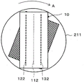
Referring to fig. 1A and 1B together, in the cleaning head 10, the ejection slit 112 having a predetermined length is formed in the air ejection chamber 11, and the suction slits 122 and 132 having a predetermined length are formed in the respective portions of the 1 st air suction chamber 121 and the 2 nd air suction chamber 13 so as to be parallel to the ejection slit 112. The air pump pressurizes the air discharge chamber 11 to discharge air from the discharge slit 112, and the suction pump depressurizes the 1 st air suction chamber 12 and the 2 nd air suction chamber 13 to introduce air into the 1 st suction chamber 12 and the 2 nd suction chamber 13 through the suction slits 122 and 132. The flow paths of the suction slits 122, 132 formed in the respective portions of the 1 st air suction chamber 12 and the 2 nd air suction chamber 13 are formed to be inclined toward the discharge slit 112 side toward the outer side. This makes it easy for the air flow discharged from the discharge slit 112 to be guided to the suction slits 122 and 132 on both sides. The flow paths of the suction slits 122 and 132 may be formed not obliquely as described above but vertically as in the case of the flow paths of the discharge slit 112.
In this foreign substance removal apparatus, one sheet (sheet-like body) of individual glass substrates W to be removed is placed on the conveyance table 15, and the conveyance table 15 is moved in the predetermined direction D, whereby one glass substrate W is moved in the direction D. The cleaning head 10 having the above-described configuration is disposed above the conveyance table 15 as follows: a predetermined gap is formed between the glass substrate W and the discharge slit 112 and the two suction slits 122 and 132 are opposed to the conveyance table 15 (see fig. 1A). In addition, the cleaning head 10 is configured in such a manner that: the discharge slit 112 and the two suction slits 122 and 132 are perpendicular to the moving direction D of the conveyance table 15 (the conveyance direction of the glass substrate W), and the 1 st air suction chamber 12 is located upstream of the 2 nd air suction chamber 13 in the conveyance direction D (see fig. 1B).
In the cleaning head 10, the air pump and the suction pump are operated to move the conveyance table 15 in the direction D while discharging air from the discharge slit 112 of the air discharge chamber 11 and sucking air into the air suction chambers 12 and 13 through the two suction slits 122 and 132. When the glass substrate W (sheet-like body) placed on the moving conveyance table 15 passes under the cleaning head 10, foreign substances (dust, dirt, etc.) on the surface of the glass substrate W are taken up by the air ejected from the ejection slit 112, and the taken-up foreign substances are sucked into the air suction chambers 12 and 13 by the introduction of the air passing through the air suction slits 122 and 132 (see fig. 1A). Thereby, the foreign matter on the surface of the glass substrate W is removed, and the surface is cleaned.
Prior art documents
Patent document
Patent document 1: japanese patent laid-open publication No. 2005-296809
Disclosure of Invention
Problems to be solved by the invention
In recent years, however, it has been desired to use the above-described cleaning head 10 for removing foreign matter from a film-like (sheet-like) substrate of a miniaturized flexible display, a film-like (sheet-like) electrode of a battery requiring a measure for mixing foreign matter, and a sheet-like film (sheet-like) insulator. In this case, since the sheet-like film (sheet-like sheet) to be subjected to the foreign matter removal is relatively thin and light, for example, as shown in fig. 2A and 2B, immediately before the downstream edge portion of the sheet-like film W passes below the ejection slit 112 provided in the air ejection chamber 11 of the cleaning head 10, the downstream edge portion may be curled up by the air ejected from the ejection slit 112. Further, the upstream edge portion of the sheet-like film W, the surface of which is moved by the air jet, may be curled up by the air jet from the jet slit 112 immediately after passing under the jet slit 112 of the cleaning head 10, as shown in fig. 3A and 3B, for example. If the downstream edge portion or the upstream edge portion of the sheet-like film W thus moved is wound up, there is a possibility that the sheet-like film cannot be appropriately conveyed and that appropriate foreign matter removal cannot be performed.
Therefore, it is conceivable to form a plurality of suction holes in the conveying table 15 and to cause the sheet-like film W placed on the conveying table 15 to be adsorbed on the conveying table 15 in advance. However, in this case, if the suction amount through each suction hole is increased in order to reliably suck the sheet-like film W onto the conveyance table 15, there is a new problem that suction marks corresponding to the suction holes or damage may occur on the sheet-like film W.
Further, it is conceivable to reduce the flow velocity of the air ejected from the ejection slit 112 by reducing the internal pressure of the air ejection chamber 11, and to reduce the pressure of the air blown onto the surface of the sheet-like film W by increasing the gap between the cleaning head 10 and the sheet-like film W. However, in these cases, a new problem arises in that the effect of removing foreign matter is reduced.
The present invention has been made in view of these circumstances, and provides a foreign substance removal apparatus and a foreign substance removal method that can remove foreign substances in a stable state without reducing the effect of foreign substance removal even when a sheet-like body to be removed is in the form of a film or a sheet and without requiring a strong adsorption and fixation structure.
Means for solving the problems
The foreign matter removing device of the present invention includes a cleaning head having a discharge slit of a predetermined length for discharging a fluid, and removes foreign matter from a surface of a sheet-like body by discharging the fluid discharged from the discharge slit at a predetermined operation flow rate to the surface of the sheet-like body while relatively moving the cleaning head and the sheet-like body, the foreign matter removing device including: a head installation mechanism that installs the cleaning head at a predetermined operation position facing the surface of the sheet-like body in a state where a flow velocity of the fluid ejected from the ejection slit is smaller than the operation flow velocity; and a rotation mechanism that rotates the cleaning head and the sheet-like body relative to each other while maintaining a state in which the cleaning head and the sheet-like body are opposed to each other in a state in which the fluid is ejected from the ejection slit at the operation flow rate after the cleaning head is set at the operation position.
According to this configuration, first, the cleaning head is set at the operation position facing the surface of the sheet-like body in a state where the flow velocity of the fluid discharged from the discharge slit is smaller than the predetermined operation flow velocity. Thus, when the cleaning head is set at the operating position, the force acting on the sheet-like body by the fluid discharged from the discharge slit can be made small. Then, the cleaning head and the sheet-like body are relatively rotated while maintaining a state in which the cleaning head and the surface of the sheet-like body are opposed to each other in a state in which the fluid is discharged from the discharge slit at a predetermined operation flow rate. In a state where the cleaning head and the sheet-like body are relatively rotated, the fluid ejected from the ejection slit of the cleaning head at the operation flow rate is ejected onto the surface of the sheet-like body. Thus, the sheet-like body can be removed of foreign matter from the surface thereof while receiving a pressing force by the ejected fluid.
In the foreign substance removal device according to the present invention, the head installation mechanism may be configured to set a flow velocity of the fluid ejected from the ejection slit to zero when the cleaning head is installed at the operation position.
According to such a configuration, the cleaning head is provided at an operation position facing the surface of the sheet-like body in a state where the flow velocity of the fluid from the ejection slit is zero, that is, the fluid is not ejected from the ejection slit. Therefore, when the cleaning head is set at the operating position, the force of the fluid ejected from the ejection slit acting on the sheet-like body can be eliminated.
In the foreign matter removal device according to the present invention, the head installation mechanism may be configured to move the cleaning head relative to the sheet-like body in a direction in which the discharge slit enters the sheet-like body from one end thereof while crossing the edge line of the sheet-like body in order, and to install the cleaning head at the operation position.
With this configuration, when the cleaning head is set at the operating position, the cleaning head moves relative to the sheet-like body in a direction in which the linear discharge slit enters the sheet-like body from one end thereof in sequence across the edge line of the sheet-like body, and therefore, the influence of the fluid discharged from the discharge slit on the edge line portion of the sheet-like body can be minimized. This can reduce the force for ejecting the edge line portion of the sheet-like body as much as possible.
The foreign matter removing device of the present invention includes a cleaning head having a discharge slit of a predetermined length for discharging a fluid, and removes foreign matter from a surface of a sheet-like body by discharging the fluid discharged from the discharge slit at a predetermined operation flow rate to the surface of the sheet-like body while relatively moving the cleaning head and the sheet-like body, the foreign matter removing device including: a head setting mechanism that moves the cleaning head relative to the sheet-like body in a direction in which the discharge slit enters the sheet-like body from one end thereof while the fluid is discharged from the discharge slit at the operating flow rate, the direction being transverse to an edge line of the sheet-like body in order, and is set at a predetermined operating position facing a surface of the sheet-like body; and a rotation mechanism that rotates the cleaning head and the sheet-like body relative to each other while maintaining a state in which the fluid is ejected from the ejection slit at the operation flow rate after the cleaning head is set at the operation position.
With this configuration, when the cleaning head is set at a predetermined operating position facing the surface of the sheet-like body in a state where the fluid is discharged from the discharge slit at a predetermined operating flow rate, the cleaning head moves relative to the sheet-like body in a direction in which the linear discharge slit enters the sheet-like body from one end thereof while sequentially crossing the edge line of the sheet-like body. This makes it possible to reduce as much as possible the influence of the fluid discharged from the discharge slit on the edge line portion of the sheet-like body, and as a result, the force with which the sheet-like body is ejected can be reduced as much as possible. Then, the cleaning head provided at the operating position facing the surface of the sheet-like body and the sheet-like body are relatively rotated while maintaining the state in which the fluid is ejected from the ejection slit at the operating flow rate. In a state where the cleaning head and the sheet-like body are relatively rotated, the fluid ejected from the ejection slit of the cleaning head at the operation flow rate is ejected onto the surface of the sheet-like body. Thus, the sheet-like body can be removed of foreign matter from the surface thereof while receiving a pressing force by the ejected fluid.
In the foreign substance removal apparatus according to the present invention, the head installation mechanism may move the cleaning head in a direction in which the discharge slit enters the sheet-like body while crossing the edge line of the sheet-like body at right angles in order from one end thereof.
With this configuration, the influence of the fluid discharged from the linear discharge slit on the edge line portion of the sheet-like body can be further reduced.
In each of the foreign substance removal apparatuses described above, the head installation mechanism may move the cleaning head, may move the sheet, or may move both the cleaning head and the sheet when the cleaning head is installed at the operating position facing the surface of the sheet.
The rotating mechanism may rotate the cleaning head while maintaining the state in which the cleaning head and the sheet-like body face each other, may rotate the sheet-like body, or may rotate both the cleaning head and the sheet-like body.
The foreign matter removing method of the present invention is a foreign matter removing method for removing foreign matter from a surface of a sheet-like body by ejecting a fluid ejected from an ejection slit at a predetermined operation flow rate to the surface of the sheet-like body while relatively moving the cleaning head having the ejection slit of a predetermined length that ejects the fluid and the sheet-like body, the foreign matter removing method including: a head setting step of setting the cleaning head at a predetermined operation position facing a surface of the sheet-like body in a state where a flow velocity of the fluid ejected from the ejection slit is smaller than the operation flow velocity; and a rotating step of relatively rotating the cleaning head and the sheet-like body while maintaining a state in which the cleaning head faces the surface of the sheet-like body and the fluid is ejected from the ejection slit at the operation flow rate after the cleaning head is set at the operation position.
Further, a foreign matter removal method according to the present invention is a foreign matter removal method for removing foreign matter from a surface of a sheet-like body by ejecting a fluid ejected from an ejection slit at a predetermined operation flow rate onto the surface of the sheet-like body while relatively moving a cleaning head having the ejection slit with a predetermined length for ejecting the fluid and the sheet-like body, the foreign matter removal method including: a head setting step of moving the cleaning head in a direction in which the discharge slit enters the sheet-like body while sequentially crossing the edge line of the sheet-like body from one end thereof in a state in which the fluid is discharged from the discharge slit at the operating flow rate, and setting the cleaning head at a predetermined operating position facing the surface of the sheet-like body; and a rotating step of rotating the cleaning head and the sheet-like body relative to each other while maintaining a state in which the fluid is ejected from the ejection slit at the operation flow rate after the cleaning head is set at the operation position.
Effects of the invention
According to the foreign substance removal apparatus and the foreign substance removal method of the present invention, even if the sheet-like body to be removed is in the form of a film or a sheet, the foreign substance removal effect is not lowered, and the foreign substance can be removed in a stable state without requiring a strong adsorption and fixation structure.
Drawings
Fig. 1A is a cross-sectional view showing a basic configuration of a cleaning head, and showing a relative positional relationship between the cleaning head and a sheet-like body conveyed by a conveying table in a conventional foreign substance removal apparatus.
Fig. 1B is a plan view showing a relative positional relationship between the cleaning head and the sheet-like body conveyed by the conveying table in the conventional foreign substance removal apparatus.
Fig. 2A is a cross-sectional view showing an example of a state in which the downstream edge portion of the sheet-like body passes below the ejection slit of the cleaning head.
Fig. 2B is a plan view showing an example of a state of the downstream side edge portion of the sheet-like body affected by air ejected from the ejection slit of the cleaning head.
Fig. 3A is a cross-sectional view showing an example of a state in which the upstream edge portion of the sheet-like body passes below the ejection slit of the cleaning head.
Fig. 3B is a plan view showing an example of a state of the upstream edge portion of the sheet-like body affected by the air ejected from the ejection slit of the cleaning head.
Fig. 4A is a side view showing the structure of a foreign substance removal apparatus according to embodiment 1 of the present invention.
Fig. 4B is a plan view showing the structure of the foreign substance removal device according to embodiment 1 of the present invention.
Fig. 5A is a side view showing a state in which the sheet-like film is conveyed by the conveying table in the foreign substance removal apparatus shown in fig. 4A and 4B.
Fig. 5B is a plan view showing a state in which the sheet-like film is conveyed by the conveying table in the foreign substance removal apparatus shown in fig. 4A and 4B.
Fig. 6A is a plan view showing (one of) the relative positional relationship between the moving sheet-like film and the cleaning head in the foreign substance removal device shown in fig. 4A and 4B.
Fig. 6B is a plan view showing the relative positional relationship (second) between the moving sheet-like film and the cleaning head in the foreign substance removal device shown in fig. 4A and 4B.
FIG. 6C is a plan view showing the relative positional relationship between the moving sheet-like film and the cleaning head (third: a state in which the cleaning head is set at the operation position) in the foreign substance removal apparatus shown in FIGS. 4A and 4B.
Fig. 7A is a side view showing a state in which the cleaning head is set at the action position in the foreign substance removal apparatus shown in fig. 4A and 4B.
Fig. 7B is a plan view showing a state in which the cleaning head is set at the operation position in the foreign substance removal apparatus shown in fig. 4A and 4B.
Fig. 8A is an enlarged plan view showing a relative positional relationship between the cleaning head and the sheet-like film in a state where the cleaning head is set at the operation position in the foreign substance removal device shown in fig. 4A and 4B.
Fig. 8B is a plan view showing a state in which the turntable on which the sheet-like film is placed is rotated in a state in which the cleaning head is set at the operating position in the foreign substance removal device shown in fig. 4A and 4B.
Fig. 9A is an enlarged plan view showing the relative positional relationship between the sheet-like film and the ejection slit and the 2 suction slits in a state where the cleaning head is set at the operation position in the foreign substance removal device shown in fig. 4A and 4B.
Fig. 9B is a plan view showing a relative positional relationship between the cleaning head provided at the operating position and the sheet-like film placed on the rotating turntable in the foreign substance removal device shown in fig. 4A and 4B.
Fig. 10 is a plan view showing a state where the sheet-like film from which the foreign substances have been removed is discharged from the turntable in the foreign substance removal device shown in fig. 4A and 4B.
Fig. 11A is a side view showing the structure of a foreign substance removal apparatus according to embodiment 2 of the present invention.
Fig. 11B is a plan view showing the structure of the foreign substance removal device according to embodiment 2 of the present invention.
Fig. 12 is a plan view showing a state in which the cleaning head is set at the operation position in the foreign substance removal apparatus shown in fig. 11A and 11B.
Fig. 13A is an enlarged plan view showing a relative positional relationship between the cleaning head and the sheet-like film in a state where the cleaning head is set at the operation position in the foreign substance removal device shown in fig. 11A and 11B.
Fig. 13B is a plan view showing a state in which the turntable on which the sheet-like film is placed is rotated in a state in which the cleaning head is set at the operating position in the foreign substance removal device shown in fig. 11A and 11B.
Fig. 14 is a plan view showing a state in which the sheet-like film from which the foreign substances have been removed is discharged from the turntable in the foreign substance removal device shown in fig. 11A and 11B.
Fig. 15A is a side view showing the structure of a foreign substance removal apparatus according to embodiment 3 of the present invention.
Fig. 15B is a plan view showing the structure of the foreign substance removal device according to embodiment 3 of the present invention.
Fig. 16A is a side view showing a state in which the cleaning head is set at the 1 st action position in the foreign substance removal apparatus shown in fig. 15A and 15B.
Fig. 16B is a plan view showing a state in which the cleaning head is set at the 1 st action position in the foreign substance removal device shown in fig. 15A and 15B.
Fig. 17 is a plan view showing a state where the 1 st turn table on which the sheet-like film is placed is rotated in a state where the cleaning head is set at the 1 st operating position in the foreign substance removal device shown in fig. 15A and 15B.
Fig. 18 is a plan view showing a state where the sheet-like film after the foreign matter is removed is discharged from the 1 st turntable in the foreign matter removal device shown in fig. 15A and 15B.
Fig. 19 is a plan view showing a state where the 2 nd turn table on which the sheet-like film is placed is rotated and a state where a new sheet-like film is thrown into the 2 nd state in the foreign substance removal device shown in fig. 15A and 15B in a state where the cleaning head is set at the 2 nd operation position.
Fig. 20 is a plan view showing a state where the cleaning head is set at the 1 st operation position and a state where the sheet-like film from which the foreign matter has been removed is discharged from the 2 nd turn table in the foreign matter removal device shown in fig. 15A and 15B.
Detailed Description
Hereinafter, embodiments of the present invention will be described with reference to the drawings.
The foreign matter removal device according to embodiment 1 of the present invention is configured as shown in fig. 4A and 4B. Fig. 4A is a side view showing the structure of the foreign substance removal device, and fig. 4B is a plan view showing the structure of the foreign substance removal device. The foreign substance removing device is a film-like substrate of a flexible display, a film-like electrode of a battery requiring a measure for mixing foreign substances, and a sheet-like film such as a film-like insulator, for example.
In fig. 4A and 4B, the foreign material transport apparatus has a cleaning head 10, a transport carriage 20, a rotation mechanism 21, and 2 guide rails 30a, 30B. The transport carriage 20 is provided on 2 guide rails 30a and 30b arranged in parallel to be capable of reciprocating. The conveyance carriage 20 is reciprocated by a conveyance drive mechanism (not shown) between a loading/unloading position (a position shown in fig. 4A and 4B) and a head installation position (a position shown in fig. 7A and 7B described later) on the two guide rails 30a and 30B. A rotating mechanism 21 is provided in the conveyance carriage 20. The rotation mechanism 21 includes: a disk-shaped turntable 211, the surface of which is exposed from the surface of the transport tray 20; and a driving unit 212 (including a motor and the like) that rotates the turntable 211 about the axis. A plurality of suction holes are formed in the surface of the turntable 211, and the sheet-like film W to be removed is placed on the turntable 211 and is sucked and fixed.
The cleaning head 10 has the same configuration as that shown in fig. 1A described above, and the 1 st air suction chamber 12, the air ejection chamber 11, and the 2 nd air suction chamber 13 are formed in a row so that the air ejection chamber 11 is sandwiched by the 1 st air suction chamber 12 and the 2 nd air suction chamber 13. The ejection slit 112 having a predetermined length is formed in the air ejection chamber 11, and the suction slits 122 and 132 are formed in parallel with the ejection slit 112 in the 1 st air suction chamber 12 and the 2 nd air suction chamber 13, respectively. The air pump pressurizes the inside of the air discharge chamber 11 to discharge air from the discharge slit 112, and the suction pump depressurizes the inside of the 1 st air suction chamber 12 and the 2 nd air suction chamber 13 to introduce the air into the 1 st suction chamber 12 and the 2 nd suction chamber 13 through the suction slits 122 and 132.
The positional relationship between the turntable 211 and the cleaning head 10 in the moving direction of the conveyance carriage 20 is as follows: when the transport tray 20 is located at the loading/discharging position, the turn table 211 and the cleaning head 10 are arranged at a predetermined interval in the moving direction, and when the transport tray 20 is located at the head installation position (see fig. 7A and 7B), the cleaning head 10 is located at a position directly above the turn table 211. The turntable 211 and the cleaning head 10 are respectively positioned at the center of the width direction (direction perpendicular to the moving direction) of the conveyance carriage 20. The cleaning head 10 makes the discharge slit 112 and the two suction slits 122 and 132 fly toward the surface of the conveyance carriage 20, and these discharge slit 112 and the two suction slits 122 and 132 are arranged parallel to the moving direction of the conveyance carriage 20. When the transport carriage 20 is located at the head installation position (see fig. 7A and 7B), the cleaning head 10 faces the transport carriage 20 so as to form a predetermined gap (for example, about 1mm to 5 mm) with the sheet-like film W placed on the turntable 211. Although not shown, a loading/discharging mechanism is provided to load the sheet-like film W to be subjected to foreign matter removal into the turntable 211 (see fig. 4B) and discharge the sheet-like film W from which the foreign matter has been removed from the turntable 211 (see fig. 10 described later) in a state where the conveyance carriage 20 is at the loading/discharging position.
The operations of the conveyance drive mechanism of the conveyance carriage 20, the drive portion 212 and the input/output mechanism of the rotation mechanism 21, the air pump for pressurizing the air discharge chamber 11 of the cleaning head 10, and the air suction pump for depressurizing the 1 st air suction chamber 12 and the 2 nd air suction chamber 13 are controlled by a control device, not shown.
The foreign substance removal device having the above-described structure operates as follows.
As shown in fig. 4A and 4B, when the conveyance carriage 20 is at the loading/discharging position, the sheet-like film W is loaded onto the turntable 211 in a predetermined posture by a loading/discharging mechanism (not shown). The sheet-like film W is placed on the center of the turntable 211 and is sucked and fixed. At this time, the cleaning head 10 separated from the turntable 211 is already in a state of ejecting air from the ejection slit 112 at a predetermined operation flow rate as in the case of removing the foreign matter. At this time, the cleaning head 10 is also in a state of sucking air through the two suction slits 122, 132. Further, the suction force of the air passing through the two suction slits 122 and 132 is controlled by controlling the pressure (pressurized state) in the air discharge chamber 11 of the cleaning head 10, controlling the flow rate of the air discharged from the discharge slit 112, and controlling the pressures (depressurized state) in the 1 st air suction chamber 12 and the 2 nd air suction chamber 13.
In the above state, the conveyance carriage 20 moves to the head installation position (see fig. 7A and 7B) on the two rails 30a and 30B.
As shown in fig. 5A and 5B, when the sheet-like film W moves in the direction D toward the head set position together with the conveyance carriage 20, the cleaning head 10 moves relatively above the sheet-like film W in a direction to enter the sheet-like film W. In this process, as shown in fig. 5B and 6A, and fig. 6B and 6C in an enlarged manner, the linear ejection slit 112 that ejects air at the operating flow velocity moves in the direction of entering the sheet-like film W from one end thereof in order to cross the edge line of the sheet-like film W at right angles. Then, when the conveyance carriage 20 moves to the head set position and stops, as shown in fig. 7A and 7B, the cleaning head 10 is positioned directly above the turntable 211 (sheet film W) and set at the action position (head set step). The conveyance carriage 20 that moves from the loading/discharging position to the head installation position on the guide rails 30a and 30b corresponds to a head installation mechanism that installs the cleaning head 10 in the operating position in a state where air is ejected from the ejection slit 112 at an operating flow rate.
In this foreign substance removal apparatus, when the cleaning head 10 is set at the operating position (see fig. 7A and 7B) as described above, the cleaning head 10 moves relative to the sheet-like film W in a direction in which the linear discharge slit 112 sequentially crosses the edge line of the sheet-like film W at right angles from one end thereof and enters the sheet-like film W (see fig. 6A, 6B, and 6C). At this time, the linear discharge slit 112 moves so as to intersect at one point Pe with respect to the edge line of the sheet-like film W as shown in fig. 6A, 6B, and 6C. Therefore, even if the air is ejected from the ejection slit 112 at the same operation flow rate as in the case of removing the foreign matter, the air ejected from the ejection slit 112 is ejected only within a limited range corresponding to the one point Pe of the edge line portion of the sheet-like film W, and the air ejected from the ejection slit 112 has little influence on the edge line portion of the sheet-like film W. As a result, when the cleaning head 10 is set at the operating position, the force for lifting the edge line portion of the sheet-like film W by the air ejected from the ejection slit 112 becomes small, and even if the suction fixing force of the sheet-like film W placed on the turntable 211 is small, the sheet-like film W does not curl up from the edge line portion, and the sheet-like film W maintains a stable posture on the turntable 211.
Next, as shown in fig. 8A in an enlarged manner together with fig. 7A and 7B, when the cleaning head 10 is set at the operating position directly above the turn table 211, the turn table 211 is rotated in a predetermined direction a as shown in fig. 8B by the operation of the driving unit 212 of the rotation mechanism 21 (rotation step). At this time, the air is ejected from the ejection slit 112 of the cleaning head 10 at the operating flow rate, and the state where the air is sucked from the two suction slits 122, 132 is maintained. In this way, during the relative rotation of the cleaning head 10 and the sheet-like film W sucked and fixed on the turntable 211, the air ejected from the ejection slit 112 of the cleaning head 10 at the above-described operation flow rate is blown to the surface of the sheet-like film W. Then, the discharged air winds up foreign matter (dust, dirt, etc.) on the surface of the sheet-like film W, and the air sucked through the two suction slits 122 and 132 sucks the wound-up foreign matter into the air suction chambers 12 and 13 (see the state of fig. 1A). Thereby, foreign matter on the surface of the sheet-like film W is removed, and the surface thereof is cleaned.
In this foreign matter removal device, as shown in fig. 9A, the cleaning head 10 disposed at the operating position is in the following state: the linear discharge slit 112 intersects with 1 edge line of the sheet-like film W sucked and fixed on the turntable 211 at a point Pe1, and intersects with an edge line of the sheet-like film W opposite to the edge line at a point Pe 2. Further, even when the cleaning head 10 and the sheet-like film W are relatively rotated by the rotation of the turntable 211, the cleaning head 10 maintains the state in which the linear discharge slit 112 intersects with 1 edge line of the sheet-like film W at one point Pe1 and intersects with an edge line of the sheet-like film W opposite to the edge line at one point Pe 2. Therefore, in the process of relative rotation between the cleaning head 10 and the sheet-like film W, the sheet-like film W is pressed by the air ejected from the ejection slit 112, and foreign matter is removed from the surface thereof. Further, since the edge line portions of the sheet-like film W eject air only in a limited range corresponding to one point Pe1 or Pe2, the air ejected from the ejection slit 112 has little influence on the edge line portions of the sheet-like film W, the sheet-like film W is not curled up from the edge line portions, and the sheet-like film W maintains a stable posture on the turntable 211.
When the turntable 211 rotates a predetermined number of times (half rotation or more) to eject air over the entire surface of the sheet-like film W in a state where air is ejected from the ejection slit 112 of the cleaning head 10 located at the operating position at an operating flow rate and air is sucked through the two suction slits 122, 132, the rotation of the turntable 211 is stopped. Then, the transport carriage 20 moves from the head installation position (see fig. 7A and 7B) to the original loading/discharging position. As shown in fig. 10, when the conveyance carriage 20 moves to the loading and unloading position and stops, the suction fixing of the sheet-like film W on the turntable 211 is released, and the sheet-like film W from which the foreign matter has been removed is discharged from the turntable 211 by the loading and discharging mechanism and stored in a predetermined case or the like. Thereafter, the foreign matter is removed from the surface of the sheet-like film W piece by piece in the same procedure (see fig. 4A, 4B, 5A, 5B, 7A, 7B, 8A, 8B, and 10).
According to the foreign substance removal apparatus according to embodiment 1 of the present invention as described above, even in a state where air is ejected from the ejection slit 112 of the cleaning head 10 at a predetermined operation flow rate, the influence of the air ejected from the ejection slit 112 on the edge line portion of the sheet-like film W is small in both cases of setting the cleaning head 10 at the operation position (see fig. 7A and 7B) and rotating the cleaning head 10 and the sheet-like film W relative to each other (see fig. 8B). Therefore, even if the force for attracting and fixing the sheet-like film W to the turntable 211 is set to be large, the foreign matter can be removed from the surface of the sheet-like film W in a stable state on the turntable 211 without reducing the effect of removing the foreign matter.
In the foreign substance removal device described above, when the cleaning head 112 is set at the operating position, the flow velocity of the air ejected from the ejection slit 112 is maintained at the operating flow velocity used for foreign substance removal, and therefore, it is not necessary to switch the flow velocity of the ejection slit 112, and the foreign substance removal process from the surface of the sheet-like film W can be performed efficiently.
When the cleaning head 112 is set at the operating position, the flow velocity of the air ejected from the ejection slit 112 can be made smaller than the operating flow velocity used for the foreign matter removal, or the air can be prevented from being ejected from the ejection slit 112 (the flow velocity is set to zero). In this case, the force with which the turntable 211 adsorbs and fixes the sheet-like film W can be further reduced, and the method is more suitable for removing foreign matter from a thin and soft sheet-like film W.
The foreign matter removal device according to embodiment 2 of the present invention is configured as shown in fig. 11A and 11B. Fig. 11A is a side view showing the structure of the foreign substance removal device, and fig. 11B is a plan view showing the structure of the foreign substance removal device.
As shown in fig. 11A and 11B, the foreign substance removal apparatus differs from the foreign substance removal apparatus of embodiment 1 (see fig. 4A and 4B) in that the cleaning head 10 is disposed so that the discharge slit 112 and the two suction slits 122 and 132 extend in a direction perpendicular to the moving direction of the transport carriage 20. The conveyance carriage 20 that reciprocates between the loading and unloading positions and the head installation position on the 2 guide rails 30a and 30b, and the rotation mechanism 21 (the turntable 211 and the drive unit 212) provided in the conveyance carriage 20 are similar to those of the foreign matter removal device according to embodiment 1.
In this foreign substance removal apparatus, the sheet-like film W from which the foreign substances are removed is fed to the turntable 211 of the transport carriage 20 located at the feeding and discharging position, and when the sheet-like film W is sucked and fixed to the turntable 211 (see fig. 11A and 11B), the transport carriage 20 moves from the feeding and discharging position to the head installation position. At this time, the cleaning head 10 does not eject air from the ejection slit 112 (the flow rate of the ejected air is zero), and suction through the suction slits 122, 132 is not performed. When the moving conveyance carriage 20 reaches the head set position while the cleaning head 10 is not operating, the cleaning head 10 is set at the operating position directly above the turntable 211 as shown in fig. 12 (head set step).
In this foreign matter removal device, when the cleaning head 10 is set at the operating position, the sheet-like film W sucked and fixed on the turntable 211 is not affected by the blown air because air is not blown out from the blowing slit 112. Therefore, even if the force for suction and fixation of the sheet-like film W is small, the edge portion is not curled up, and a stable posture can be maintained on the turntable 211.
Next, as shown in fig. 13A in an enlarged manner together with fig. 12, when the cleaning head 10 is set at the operating position directly above the turn table 211, the turn table 211 is rotated in a predetermined direction a as shown in fig. 13B by the operation of the driving unit 212 of the rotation mechanism 21 (rotation step). At this time, air is ejected from the ejection slit 112 of the cleaning head 10 at a predetermined operation flow rate, and air is sucked through the two suction slits 122, 132. Accordingly, similarly to the foreign substance removal device according to embodiment 1 (see fig. 8A, 8B, 9A, and 9B), the air ejected from the ejection slit 112 of the cleaning head 10 at the above-described operation flow rate is blown onto the surface of the sheet-like film W rotating together with the turntable 211. Then, the discharged air winds up foreign matter (dust, dirt, etc.) on the surface of the sheet-like film W, and the air sucked through the two suction slits 122 and 132 sucks the wound-up foreign matter into the air suction chambers 12 and 13 (see the state of fig. 1A). Thereby, foreign matter on the surface of the sheet-like film W is removed, and the surface thereof is cleaned.
In this way, in the process of ejecting the gas ejected at the operating flow rate from the ejection slit 112 of the cleaning head 10 toward the rotating sheet-like film W, since the edge line portions of the sheet-like film W eject the air only in a limited range corresponding to 1 point as in the foreign matter removal device of embodiment 1 described above, the influence of the air ejected from the ejection slit 112 on the edge line portions of the sheet-like film W is extremely small, the sheet-like film W does not curl up from the edge line portions, and the sheet-like film W maintains a stable posture on the turntable 211.
When the turntable 211 rotates a predetermined number of times and the process of removing foreign matter on the surface of the sheet-like film W is completed, the conveyance carriage 20 located at the head installation position returns to the loading/discharging position. Then, the suction fixing of the sheet-like film W on the turntable 211 is released, and as shown in fig. 14, the sheet-like film W from which the foreign matter has been removed is discharged from the turntable 211 by the loading and discharging mechanism and stored in a predetermined case or the like. Thereafter, the foreign matter is removed from the surface of the sheet-like film W piece by piece in the same procedure (see fig. 11A, 11B, 12, 13A, 13B, and 14).
According to the foreign substance removal apparatus according to embodiment 2 of the present invention, since the cleaning head 10 is set at the operating position without ejecting air from the ejection slit 112 of the cleaning head 10, when the edge line portion of the sheet-like film W sucked and fixed to the turn table 10 passes below the ejection slit 112 of the cleaning head 10, the edge line portion is not affected by the ejected air. Also when the cleaning head 10 and the sheet-like film W are relatively rotated (see fig. 13B), the influence of the air ejected from the ejection slit 112 on the edge line portion of the sheet-like film W is small, as in the case of the foreign substance removal device according to embodiment 1 described above. Therefore, even if the force for attracting and fixing the sheet-like film W to the turntable 211 is set to be large, the foreign matter can be removed from the surface of the sheet-like film W in a stable state on the turntable 211 without reducing the effect of removing the foreign matter.
In the foreign substance removal apparatus according to embodiment 2, when the cleaning head 10 is set at the operation position (see fig. 12 and 13A), air is not ejected from the ejection slit 112 (the flow velocity is zero), but the present invention is not limited to this. The air may be ejected from the ejection slit 112 at a predetermined flow rate smaller than the operating flow rate. Even in this case, when the cleaning head 10 is set at the operating position, the force with which the air ejected from the ejection slit 112 acts on the sheet-like film W can be made small, and therefore, the posture of the sheet-like film W can be stably maintained by appropriately adjusting the strength of the suction fixation on the turntable 211 within a range in which no suction mark is generated on the sheet-like film W.
The foreign matter removal device according to embodiment 3 of the present invention is configured as shown in fig. 15A and 15B. Fig. 15A is a side view showing the structure of the foreign substance removal device, and fig. 15B is a plan view showing the structure of the foreign substance removal device.
As shown in fig. 15A and 15B, the foreign substance removal apparatus is different from the foreign substance removal apparatus according to embodiment 1 (see fig. 4A and 4B) and the foreign substance removal apparatus according to embodiment 2 (see fig. 11A and 11B) in that two rotation mechanisms, i.e., a 1 st rotation mechanism 21 and a 2 nd rotation mechanism 22, are provided on the conveyance carriage 20. The configuration of the transport carriage 20 that reciprocates on the two guide rails 30a and 30b is the same as that of the foreign matter removal apparatuses according to embodiments 1 and 2, respectively.
In this foreign matter removal device, the 1 st turn table 211 of the 1 st rotation mechanism 21 and the 2 nd turn table 221 of the 2 nd rotation mechanism 22 are disposed at a predetermined interval on the conveyance tray 20 along the moving direction thereof. The 1 st turntable 211 is rotated by the 1 st driving part 212, and the 2 nd turntable 221 is rotated by the 2 nd driving part 222. These 1 st drive unit 212 and 2 nd drive unit 222 are controlled by the control device described above. The surface of the 1 st turn table 211 and the surface of the 2 nd turn table 221 are exposed from the surface of the conveyance holder 20.
The conveyance carriage 20 reciprocates between a 1 st position (a position shown in fig. 15A and 15B) and a 2 nd position (a position shown in fig. 16A and 16 described later) on the two guide rails 30a and 30B. The cleaning head 10 is disposed at a position directly above the 2 nd turn table 221 when the transport tray 20 is at the 1 st position (see fig. 15A and 15B), and at a position directly above the 1 st turn table 211 when the transport tray 20 is at the 2 nd position (see fig. 16A and 16B). Similarly to the foreign substance removal apparatus according to embodiment 1 (see fig. 4A and 4B), the cleaning head 10 is configured such that the linear discharge slit 112 and the two suction slits 122 and 132 extend parallel to the conveyance direction of the conveyance carriage 20. Further, a predetermined gap (for example, about 1mm to 5 mm) is formed between the cleaning head 10 provided above the transport carriage 20 and the sheet-like film W sucked and fixed to the turn tables 211 and 221.
The foreign substance removal device operates as follows while blowing air from the blowing slit 112 of the cleaning head 10 at an operation flow rate used for removing foreign substances and maintaining the state of sucking air through the two suction slits 122, 132.
As shown in fig. 15A and 15B, when the conveyance carriage 20 is at the 1 st position, the sheet-like film W1 to be removed is fed onto the 1 st turntable 211 by the feeding and discharging mechanism, and the sheet-like film W1 is placed on the 1 st turntable 211 and fixed by suction. In this way, the conveyance carriage 20 moves while the sheet-like film W1 is sucked and fixed to the 1 st turn table 211, and stops when it reaches the 2 nd position as shown in fig. 16A and 16B. When the conveyance carriage 20 is located at the 2 nd position, the cleaning head 10 is located directly above the 1 st turn table 211 and is set at the 1 st action position. At this time, another sheet-like film W2 to be removed of foreign matter is fed onto the 2 nd turntable 221 by another feeding and discharging mechanism, and each sheet-like film W2 is placed on the 2 nd turntable 221 and fixed by suction.
In this state, as shown in fig. 17, the 1 st turntable 211 rotates. By the rotation of the 1 st turn table 211, the cleaning head 10 disposed at the 1 st operating position and the sheet-like film W1 sucked and fixed to the 1 st turn table 211 are relatively rotated, and in this process, the air ejected from the ejection slit 112 of the cleaning head 10 at the operating flow rate is blown to the surface of the sheet-like film W1, and the foreign matter on the surface of the sheet-like film W1 is removed.
When the 1 st turn table 211 is rotated a predetermined number of times to complete the process of removing the foreign matter from the sheet film W1, the conveyance carriage 20 returns to the 1 st position. When the conveyance carriage 20 is located at the 1 st position, as shown in fig. 18, the sheet-like film W1 from which the foreign matter has been removed is discharged from the 1 st turntable 211 by the throw-in/discharge mechanism, and is stored in a predetermined case or the like. On the other hand, when the transport tray 20 returns to the 1 st position, the cleaning head 10 is positioned directly above the 2 nd turn table 221 and set at the 2 nd operating position.
When the cleaning head 10 is set at the 2 nd action position, as shown in fig. 19, the 2 nd turn table 221 rotates. By the rotation of the 2 nd turn table 221, the cleaning head 10 disposed at the 2 nd operation position and the sheet-like film W2 sucked and fixed to the 2 nd turn table 221 are relatively rotated, and in this process, the air ejected from the ejection slit 112 of the cleaning head 10 at the operation flow rate is blown to the surface of the sheet-like film W2, and the foreign matter on the surface of the sheet-like film W2 is removed.
As described above, after the sheet-like film W1 (see fig. 18) from which the foreign matter has been removed is discharged from the 1 st turntable 211, a new sheet-like film W3 is put into the 1 st turntable 211 and the new sheet-like film W3 is sucked and fixed on the 1 st turntable 211 at an appropriate timing before the foreign matter removal processing of the sheet-like film W2 sucked and fixed on the 2 nd turntable 221 which is rotated is finished by the cleaning head 10 provided at the 2 nd operating position, as shown in fig. 19.
After that, the conveyance carriage 20 moves from the 1 st position shown in fig. 19 to the 2 nd position shown in fig. 20. When the transport tray 20 is located at the 2 nd position in this way, as shown in fig. 20, the sheet-like film W2 from which the foreign matter has been removed is discharged from the 2 nd turn table 221 by the throw-in/discharge mechanism and is stored in a predetermined case or the like. The cleaning head 10 is positioned directly above the 1 st turn table 211 and is set at the 1 st operating position. Then, as described above, the foreign substances adsorbed and fixed to the surface of the sheet-like film W3 on the 1 st turn table 211 rotated by the cleaning head 10 are removed.
Thereafter, according to the same procedure (see fig. 16A, 16B, 17, 18, 19, and 20), the sheet-like films W alternately fed to the 1 st turntable 211 and the 2 nd turntable 221 are subjected to foreign matter removal by the single cleaning head 10 while the transport carriage 20 reciprocates between the 1 st position and the 2 nd position, and the sheet-like films W after the foreign matter removal are alternately discharged from the 1 st turntable 211 and the 2 nd turntable 221.
According to the foreign substance removal apparatus of embodiment 3 of the present invention, the sheet-like films W alternately put on the 1 st turntable 211 and the 2 nd turntable 221 are subjected to the foreign substance removal process by the single cleaning head 10, and the sheet-like films W from which the foreign substances have been removed are alternately discharged from the 1 st turntable 211 and the 2 nd turntable 221, so that the foreign substance removal process on the sheet-like films W can be more effectively performed.
Further, similarly to the foreign substance removal apparatus according to embodiment 1 of the present invention, even in a state where air is ejected from the ejection slit 112 of the cleaning head 10 at a predetermined operation flow rate, the influence of the air ejected from the ejection slit 112 on the edge line portion of the sheet-like film W is small in both cases where the cleaning head 10 is set at the 1 st operation position (see fig. 16A and 16B) and the 2 nd operation position (see fig. 18) and where the cleaning head 10 and the sheet-like film W are relatively rotated (see fig. 17 and 19). Therefore, even if the force for attracting and fixing the sheet-like film W to the respective turn tables 211 and 221 is set to be large, foreign matter can be removed from the surface of the sheet-like film W in a state where the sheet-like film W is stabilized on the respective turn tables 211 and 221 without reducing the effect of removing foreign matter.
The configuration in which two rotation mechanisms are provided in embodiment 3 is applied to the foreign substance removal apparatus of embodiment 1, and may also be applied to the foreign substance removal apparatus of embodiment 2.
In the foreign substance removal apparatuses according to the above embodiments, the sheet-like film W may be fixed and the cleaning head 10 may be reciprocated, or both the sheet-like film W and the cleaning head 10 may be reciprocated. Similarly, the sheet-like film W may be fixed and the cleaning head 10 may be rotated, or both the sheet-like film W and the cleaning head 10 may be rotated.
The sheet-like body to be a foreign object is not limited to a film-like structure (sheet-like film), and may be a sheet-like structure (sheet-like sheet) thicker than the film-like structure, or may be a plate-like structure (sheet-like plate) thicker than the sheet-like structure.
As long as at least the discharge slit 112 is formed in the cleaning head 10, a plurality of discharge slits may be formed, only one suction slit may be formed in addition to the discharge slit, or no suction slit may be formed. In addition, when one or more discharge slits and one or more suction slits are formed in the cleaning head 10, the arrangement thereof is not particularly limited. For example, in the cleaning head 10 described above, each slit may be formed so that one suction slit is sandwiched between two discharge slits.
The fluid ejected from the ejection slit 112 is not limited to air, and may be other gases, and may be a liquid such as water or a cleaning liquid in a cleaning apparatus or the like as a foreign substance removal apparatus for cleaning a sheet-like substrate such as a glass substrate.
While the embodiments and the modifications of the respective parts of the present invention have been described above, these embodiments and modifications of the respective parts are presented as examples and are not intended to limit the scope of the present invention. The above-described new embodiments can be implemented in various other forms, and various omissions, substitutions, and changes can be made without departing from the spirit of the present invention. These embodiments and modifications thereof are included in the scope and gist of the invention, and are included in the invention described in the claims.
Industrial applicability
As described above, the foreign substance removal apparatus and the foreign substance removal method of the present invention are useful as a foreign substance removal apparatus and a foreign substance removal method as follows: even if the sheet-like body to be subjected to foreign matter removal is in the form of a film or a sheet, the effect of foreign matter removal is not reduced, and the foreign matter can be removed in a stable state without requiring a strong adsorption and fixation structure.
Description of the reference symbols
10: a cleaning head; 11: an air ejection chamber; 12: 1 st air suction chamber; 13: a 2 nd air suction chamber; 111. 121, 131: a through hole; 112: spraying out the seam; 122. 132: a suction slot; 20: a carrying bracket; 21: a rotation mechanism; 211: a turntable; 212: a drive section; 30a, 30 b: a guide rail.
Claims (10)
1. A foreign matter removing device includes a cleaning head having a predetermined length of discharge slit for discharging gas and a predetermined length of suction slit, and removes foreign matter from the surface of a film-like or sheet-like body by discharging gas discharged from the discharge slit at a predetermined operation flow rate to the surface of the sheet-like body while relatively moving the cleaning head and the sheet-like body,
the foreign matter removing device comprises:
a head installation mechanism that installs the cleaning head at a predetermined operation position facing the surface of the sheet-like body in a state where a flow velocity of the gas ejected from the ejection slit is smaller than the operation flow velocity; and
and a rotation mechanism that rotates the cleaning head and the sheet-like body relative to each other while maintaining a state in which the cleaning head is opposed to the surface of the sheet-like body and the gas is ejected from the ejection slit at the operation flow rate and the gas is sucked through the suction slit after the cleaning head is set at the operation position.
2. The foreign matter removal apparatus according to claim 1,
when the head installation mechanism installs the cleaning head at the action position, the flow velocity of the gas ejected from the ejection slit is set to zero.
3. The foreign matter removal apparatus according to claim 1,
the head unit setting mechanism moves the cleaning head relative to the sheet-like member in a direction in which the discharge slit enters the sheet-like member while sequentially crossing the edge line of the sheet-like member from one end thereof, and sets the cleaning head at the operation position.
4. A foreign matter removing device includes a cleaning head having a predetermined length of discharge slit for discharging gas and a predetermined length of suction slit, and removes foreign matter from the surface of a film-like or sheet-like body by discharging gas discharged from the discharge slit at a predetermined operation flow rate to the surface of the sheet-like body while relatively moving the cleaning head and the sheet-like body,
the foreign matter removing device comprises:
a head installation mechanism that moves the cleaning head relative to the sheet-like body in a direction in which the discharge slit enters the sheet-like body from one end thereof while the gas is discharged from the discharge slit at the operating flow rate, the direction being such that the cleaning head crosses the edge line of the sheet-like body in order, and is installed at a predetermined operating position facing the surface of the sheet-like body; and
and a rotation mechanism that rotates the cleaning head and the sheet-like body relative to each other while maintaining a state in which the cleaning head is set at the operation position and the gas is ejected from the ejection slit at the operation flow rate and the gas is sucked through the suction slit.
5. The foreign matter removal apparatus according to claim 4,
the head setting mechanism moves the cleaning head in a direction in which the ejection slit enters the sheet-like body from one end thereof while sequentially crossing the edge line of the sheet-like body at right angles.
6. The foreign matter removal apparatus according to any one of claims 1 to 5,
the rotation mechanism has a sheet rotation mechanism that rotates the sheet relative to the stationary cleaning head.
7. A method for removing foreign matter, which removes foreign matter from the surface of a sheet-like body by ejecting gas ejected from an ejection slit at a predetermined operation flow rate to the surface of the sheet-like body while relatively moving a cleaning head having the ejection slit with a predetermined length for ejecting gas and a suction slit with a predetermined length to the sheet-like body in a film-like or sheet-like shape, and sucking the gas through the suction slit,
the foreign matter removal method comprises:
a head setting step of setting the cleaning head at a predetermined operation position facing a surface of the sheet-like body in a state where a flow velocity of the gas ejected from the ejection slit is smaller than the operation flow velocity; and
and a rotating step of relatively rotating the cleaning head and the sheet-like body while maintaining a state in which the cleaning head is opposed to the surface of the sheet-like body and the gas is ejected from the ejection slit at the operation flow rate and the gas is sucked through the suction slit after the cleaning head is set at the operation position.
8. The foreign matter removal method according to claim 7,
the flow rate of the gas ejected from the ejection slit is set to zero when the cleaning head is set at the operating position in the head setting step.
9. A method for removing foreign matter, which removes foreign matter from the surface of a sheet-like body by ejecting gas ejected from an ejection slit at a predetermined operation flow rate to the surface of the sheet-like body while relatively moving a cleaning head having the ejection slit with a predetermined length for ejecting gas and a suction slit with a predetermined length to the sheet-like body in a film-like or sheet-like shape, and sucking the gas through the suction slit,
the foreign matter removal method comprises:
a head setting step of moving the cleaning head in a direction in which the discharge slit enters the sheet-like body while sequentially crossing the edge line of the sheet-like body from one end thereof in a state in which the gas is discharged from the discharge slit at the operating flow rate, and setting the cleaning head at a predetermined operating position facing the surface of the sheet-like body; and
and a rotation step of rotating the cleaning head and the sheet-like body relative to each other while maintaining a state in which the cleaning head is set at the operation position and the gas is ejected from the ejection slit at the operation flow rate and the gas is sucked through the suction slit.
10. The foreign matter removal method according to claim 9,
in the head portion setting step, the cleaning head is moved in a direction in which the discharge slit enters the sheet-like body while sequentially crossing the edge line of the sheet-like body at right angles from one end thereof.
Applications Claiming Priority (3)
| Application Number | Priority Date | Filing Date | Title |
|---|---|---|---|
| JP2016255096A JP6975953B2 (en) | 2016-12-28 | 2016-12-28 | Foreign matter removal device and foreign matter removal method |
| JP2016-255096 | 2016-12-28 | ||
| PCT/JP2017/045465 WO2018123715A1 (en) | 2016-12-28 | 2017-12-19 | Foreign-matter removing device and foreign-matter removing method |
Publications (2)
| Publication Number | Publication Date |
|---|---|
| CN110087784A CN110087784A (en) | 2019-08-02 |
| CN110087784B true CN110087784B (en) | 2022-03-18 |
Family
ID=62708125
Family Applications (1)
| Application Number | Title | Priority Date | Filing Date |
|---|---|---|---|
| CN201780078289.0A Active CN110087784B (en) | 2016-12-28 | 2017-12-19 | Foreign matter removing device and foreign matter removing method |
Country Status (5)
| Country | Link |
|---|---|
| JP (1) | JP6975953B2 (en) |
| KR (1) | KR102157973B1 (en) |
| CN (1) | CN110087784B (en) |
| TW (1) | TWI668056B (en) |
| WO (1) | WO2018123715A1 (en) |
Families Citing this family (4)
| Publication number | Priority date | Publication date | Assignee | Title |
|---|---|---|---|---|
| US11318509B2 (en) * | 2017-11-06 | 2022-05-03 | Air Systems Design, Inc. | Dust hood |
| CN110963564B (en) * | 2019-12-19 | 2020-08-18 | 浙江海盐力源环保科技股份有限公司 | Treatment equipment for removing heavy metal ions in industrial wastewater |
| JP7347809B2 (en) * | 2020-03-10 | 2023-09-20 | ヒューグル開発株式会社 | Dust removal equipment and dust removal method |
| JP7436267B2 (en) * | 2020-04-03 | 2024-02-21 | 株式会社ディスコ | Cleaning nozzle and cleaning method |
Citations (12)
| Publication number | Priority date | Publication date | Assignee | Title |
|---|---|---|---|---|
| CN1575872A (en) * | 2003-07-17 | 2005-02-09 | 索尼株式会社 | A cleaning device and cleaning method |
| CN1883035A (en) * | 2003-11-18 | 2006-12-20 | 东京毅力科创株式会社 | Substrate cleaning method, substrate cleaning apparatus and computer-readable recording medium |
| CN101327572A (en) * | 2007-06-22 | 2008-12-24 | 中芯国际集成电路制造(上海)有限公司 | Technique for thinning back side of silicon wafer |
| CN100508159C (en) * | 2004-06-14 | 2009-07-01 | 大日本网目版制造株式会社 | Substrate processing apparatus and method |
| CN101551602A (en) * | 2008-04-03 | 2009-10-07 | 东京毅力科创株式会社 | Substrate cleaning method and substrate cleaning apparatus |
| JP2013051301A (en) * | 2011-08-31 | 2013-03-14 | Dainippon Screen Mfg Co Ltd | Substrate processing apparatus and substrate processing method |
| JP2014017466A (en) * | 2012-06-13 | 2014-01-30 | Dainippon Screen Mfg Co Ltd | Substrate processing apparatus and substrate processing method |
| CN103567188A (en) * | 2012-08-06 | 2014-02-12 | 修谷鲁开发股份有限公司 | Cleaning head |
| CN103817109A (en) * | 2012-11-16 | 2014-05-28 | 株式会社日藤工业 | Dust collector |
| CN103977973A (en) * | 2014-05-09 | 2014-08-13 | 欧蒙医学诊断(中国)有限公司 | Carrying sheet cleaning device and method |
| CN104051304A (en) * | 2013-03-15 | 2014-09-17 | 大日本网屏制造株式会社 | Substrate treatment apparatus and substrate treatment method |
| CN104205305A (en) * | 2012-03-23 | 2014-12-10 | 大日本网屏制造株式会社 | Substrate processing apparatus and heater cleaning method |
Family Cites Families (22)
| Publication number | Priority date | Publication date | Assignee | Title |
|---|---|---|---|---|
| JPS62119781A (en) * | 1985-11-20 | 1987-06-01 | Hitachi Ltd | surface cleaning equipment |
| GB2282463A (en) * | 1993-09-10 | 1995-04-05 | Manfred George Michelson | Cleaning photographic film |
| JPH1064868A (en) * | 1996-08-15 | 1998-03-06 | Dainippon Screen Mfg Co Ltd | Device and method for cleaning substrate |
| JPH11300301A (en) * | 1998-04-27 | 1999-11-02 | Dainippon Screen Mfg Co Ltd | Method of washing substrate and device therefor |
| JP2000262989A (en) * | 1999-01-13 | 2000-09-26 | Uct Kk | Substrate washing device |
| EP1091388A3 (en) * | 1999-10-06 | 2005-09-21 | Ebara Corporation | Method and apparatus for cleaning a substrate |
| JP2001156033A (en) * | 1999-11-25 | 2001-06-08 | Yokogawa Electric Corp | Method and apparatus for dry cleaning |
| JP3728406B2 (en) * | 2000-06-15 | 2005-12-21 | シャープ株式会社 | Substrate cleaning device |
| US6565711B1 (en) * | 2000-08-05 | 2003-05-20 | Kleissler Jr Edwin A | Method for controlling dust on paper machinery and the like |
| JP3625766B2 (en) * | 2000-12-27 | 2005-03-02 | 大日本スクリーン製造株式会社 | Substrate surface treatment apparatus and substrate surface treatment method |
| JP4179592B2 (en) * | 2002-08-21 | 2008-11-12 | 大日本スクリーン製造株式会社 | Substrate peripheral processing apparatus and substrate peripheral processing method |
| JP2005296809A (en) | 2004-04-12 | 2005-10-27 | Hugle Electronics Inc | Apparatus for detecting foreign matter for dust collector |
| JP2005349291A (en) * | 2004-06-10 | 2005-12-22 | Sharp Corp | Spin washing apparatus |
| JP4255459B2 (en) * | 2005-06-15 | 2009-04-15 | 大日本スクリーン製造株式会社 | Substrate cleaning apparatus and substrate cleaning method |
| JP4579071B2 (en) * | 2005-07-06 | 2010-11-10 | ヒューグルエレクトロニクス株式会社 | Substrate transport dust remover |
| JP5016351B2 (en) * | 2007-03-29 | 2012-09-05 | 東京エレクトロン株式会社 | Substrate processing system and substrate cleaning apparatus |
| JP5403407B2 (en) * | 2008-06-18 | 2014-01-29 | 株式会社リコー | Cleaning device |
| JP5889537B2 (en) * | 2011-03-23 | 2016-03-22 | ファスフォードテクノロジ株式会社 | Die bonder |
| JP6182347B2 (en) * | 2013-04-19 | 2017-08-16 | 株式会社荏原製作所 | Substrate processing equipment |
| KR101598360B1 (en) * | 2014-09-05 | 2016-02-29 | 지에스티 반도체장비(주) | Substrate position controller for cleaning thereof |
| JP6504890B2 (en) * | 2015-04-09 | 2019-04-24 | 東京エレクトロン株式会社 | Foreign matter removing device, foreign matter removing method and stripping device |
| CN105977547B (en) * | 2016-05-18 | 2018-09-18 | 合肥国轩高科动力能源有限公司 | Cleaning device and cleaning method for wound and laminated battery pole piece |
-
2016
- 2016-12-28 JP JP2016255096A patent/JP6975953B2/en active Active
-
2017
- 2017-12-19 WO PCT/JP2017/045465 patent/WO2018123715A1/en active Application Filing
- 2017-12-19 KR KR1020197018146A patent/KR102157973B1/en active Active
- 2017-12-19 CN CN201780078289.0A patent/CN110087784B/en active Active
- 2017-12-25 TW TW106145506A patent/TWI668056B/en active
Patent Citations (12)
| Publication number | Priority date | Publication date | Assignee | Title |
|---|---|---|---|---|
| CN1575872A (en) * | 2003-07-17 | 2005-02-09 | 索尼株式会社 | A cleaning device and cleaning method |
| CN1883035A (en) * | 2003-11-18 | 2006-12-20 | 东京毅力科创株式会社 | Substrate cleaning method, substrate cleaning apparatus and computer-readable recording medium |
| CN100508159C (en) * | 2004-06-14 | 2009-07-01 | 大日本网目版制造株式会社 | Substrate processing apparatus and method |
| CN101327572A (en) * | 2007-06-22 | 2008-12-24 | 中芯国际集成电路制造(上海)有限公司 | Technique for thinning back side of silicon wafer |
| CN101551602A (en) * | 2008-04-03 | 2009-10-07 | 东京毅力科创株式会社 | Substrate cleaning method and substrate cleaning apparatus |
| JP2013051301A (en) * | 2011-08-31 | 2013-03-14 | Dainippon Screen Mfg Co Ltd | Substrate processing apparatus and substrate processing method |
| CN104205305A (en) * | 2012-03-23 | 2014-12-10 | 大日本网屏制造株式会社 | Substrate processing apparatus and heater cleaning method |
| JP2014017466A (en) * | 2012-06-13 | 2014-01-30 | Dainippon Screen Mfg Co Ltd | Substrate processing apparatus and substrate processing method |
| CN103567188A (en) * | 2012-08-06 | 2014-02-12 | 修谷鲁开发股份有限公司 | Cleaning head |
| CN103817109A (en) * | 2012-11-16 | 2014-05-28 | 株式会社日藤工业 | Dust collector |
| CN104051304A (en) * | 2013-03-15 | 2014-09-17 | 大日本网屏制造株式会社 | Substrate treatment apparatus and substrate treatment method |
| CN103977973A (en) * | 2014-05-09 | 2014-08-13 | 欧蒙医学诊断(中国)有限公司 | Carrying sheet cleaning device and method |
Also Published As
| Publication number | Publication date |
|---|---|
| TW201829079A (en) | 2018-08-16 |
| JP2018103153A (en) | 2018-07-05 |
| WO2018123715A1 (en) | 2018-07-05 |
| JP6975953B2 (en) | 2021-12-01 |
| KR20190089182A (en) | 2019-07-30 |
| CN110087784A (en) | 2019-08-02 |
| KR102157973B1 (en) | 2020-09-18 |
| TWI668056B (en) | 2019-08-11 |
Similar Documents
| Publication | Publication Date | Title |
|---|---|---|
| CN110087784B (en) | Foreign matter removing device and foreign matter removing method | |
| CN107614404A (en) | Cleaning method of liquid ejection device and conveyor belt of liquid ejection device | |
| JP4644726B2 (en) | Coating device | |
| TWI577254B (en) | Chip separation method for circuit board and chip separation device for circuit board | |
| JP5254114B2 (en) | Wafer transfer method and wafer transfer apparatus | |
| KR101069600B1 (en) | Inline type substrate coater apparatus and method thereof | |
| CN103770013B (en) | Blasting apparatus and method for blasting | |
| GB2528052A (en) | Contact cleaning apparatus | |
| KR101081885B1 (en) | Substrate coater apparatus | |
| JP2007196094A (en) | Treatment liquid supply unit and substrate treatment apparatus equipped with the same | |
| JP5372363B2 (en) | Inkjet recording device | |
| JP2011194297A (en) | Suction device and droplet discharge device | |
| CN106183452A (en) | Liquid discharge device | |
| KR20170140567A (en) | Coating apparatus | |
| JP2005272113A (en) | Substrate carrying device and substrate carrying method | |
| CN106183410A (en) | Liquid discharge device | |
| KR20190013498A (en) | Device for preventing dust scattering and substrate machining apparatus having the same | |
| JP6544539B2 (en) | Injection processing apparatus and surface processing method of workpiece | |
| EP2204344B1 (en) | Nip device and nip method | |
| JP5848812B1 (en) | Adsorption device and control method of adsorption device | |
| JP2009289780A (en) | Substrate conveying device | |
| CN116457113A (en) | Dust removal device | |
| KR20240094671A (en) | Inkjet printing system | |
| CN111883454A (en) | Dummy portion removing unit and dummy portion removing method using the same | |
| JP2000094319A (en) | Separation method of platelike body and device thereof |
Legal Events
| Date | Code | Title | Description |
|---|---|---|---|
| PB01 | Publication | ||
| PB01 | Publication | ||
| SE01 | Entry into force of request for substantive examination | ||
| SE01 | Entry into force of request for substantive examination | ||
| GR01 | Patent grant | ||
| GR01 | Patent grant |