Disclosure of Invention
In order to solve the problems, the invention provides a magnetic suspension rotor vibration measuring method based on vision according to a phase-based computer theory under the existing vision measuring method. According to a motor vibration video sequence acquired by a high-speed camera, a direction-controllable pyramid is designed to convert an image from a spatial domain to a frequency domain, inter-frame displacement motion information is obtained by utilizing the phase change relation between a reference frame and a motion frame, a vibration acceleration signal is obtained and converted into a spectrogram, and a frequency signal of a magnetic suspension rotor is measured.
The specific technical scheme is as follows:
a magnetic suspension rotor vibration measurement method based on vision comprises the following steps:
s1, acquiring vibration videos of a magnetic suspension rotor in different working states through a high-speed camera provided with an optical lens;
s2, converting image space domain information contained in the vibration video by adopting a direction controllable pyramid constructed on the basis of a Gabor filter to obtain image frequency domain information with different scales and different directions, and extracting a vibration displacement signal of the magnetic suspension motor according to local phase change in the image frequency domain information;
s3, performing second-order derivation on the vibration displacement signal by adopting an LOG operator, and calculating to obtain an acceleration signal;
and S4, carrying out fast Fourier transform on the acceleration signal to obtain a target spectrogram.
Preferably, the step S2 specifically includes:
s21, designing a Gabor filter by using a two-dimensional Gabor wavelet as a convolution kernel function, and converting video image space domain information contained in the vibration video into frequency domain information through the Gabor filter; a low-pass sub-band part in the frequency domain information contains global information of the video image, and a high-pass sub-band part contains detail information of the video image; the two-dimensional Gabor function expression corresponding to the Gabor filter is as follows:
wherein x and y represent spatial pixel coordinates; theta epsilon (0 degrees, 360 degrees) represents the direction of the parallel strips in the Gabor filter kernel; λ is the wavelength of the sine function; ψ is the phase offset of the tuning function; γ is the spatial aspect ratio; σ represents the standard deviation of the Gaussian function; x is the number ofθAnd yθEach represents a spatial variable containing directional information, and the expression is as follows:
xθ=xcosθ+ysinθ,yθ=-xsinθ+ycosθ
s22, linearly combining a plurality of Gabor filters in different directions, and simultaneously carrying out scale transformation on the video image so as to construct a direction-controllable pyramid;
s23, decomposing the video image into a sub-band series with different scales and multiple directions containing the structure information and the edge information of the video image through the direction controllable pyramid, thereby completing the conversion of the video image information into frequency domain information with different scales and different directions; and calculating the phase difference of the two frames according to the phase angles of the two frames in the frequency domain information, thereby obtaining the displacement signals in the corresponding directions.
Preferably, the implementation process of the direction controllable pyramid is as follows:
the video image is first passed through a high pass filter H0(ω) and a low-pass filter L0(omega) is decomposed into two sub-bands of high pass and low pass; the low-pass subband image is then decomposed into K different directional band-pass subbands Bk-1(omega) and the low-pass sub-band L1(ω) for low-pass sub-band L simultaneously1The rows and columns of (omega) are respectively sampled again; and repeating the decomposition process after two samples, and circularly iterating until one dimension of the row and the column cannot be subjected to down sampling.
Preferably, the calculation method for calculating the phase difference between two frames according to the phase angles of the two frames in the frequency domain information to obtain the displacement signal in the corresponding direction is as follows:
assuming that the temporal interval between two successive frames of the video is Δ t, local motion (Δ x, Δ y) occurs at a spatial position (x, y), the first frame is defined as the image intensity I (x, y, t)0) The second frame is defined as the image intensity I (x + Deltax, y + Deltay, t)0Motion frame of +. DELTA.t);
the convolution operation is performed by using a two-dimensional Gabor function, and the image intensity I (x, y, t) is converted into frequency domain information F (x, y, t) as follows:
expressed in the form of an integral:
taking the example of extracting horizontal motion, let the spatial variable be represented as xθ=x、yθY, the reference frame is converted into:
the motion frame is converted into:
rearranging the above reference frame conversion formula and motion frame conversion formula, putting the phase term independent of the integration variable outside the integration, and then simplifying the equation:
expressing the phase part of the above expression as
The phase terms of the simplified reference frame conversion formula and the simplified motion frame conversion formula are
The final definite integral result is therefore the same, which is denoted as
The phase angles for the two frames are calculated as follows:
the phase difference of two frames in the horizontal direction is calculated as follows:
thereby obtaining a displacement signal in the corresponding direction.
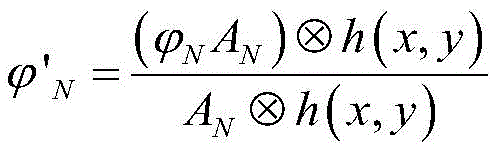
Preferably, step S23 further includes performing weighted spatial gaussian blurring on the phase angle to improve the signal-to-noise ratio, specifically including:
weighting the phase signals for the Nth frame
The calculation is as follows:
wherein A is
NWhich represents the amplitude of the nth frame,
indicating the phase of the nth frame; h (x, y) is a two-dimensional gaussian function, expressed as:
wherein the standard deviation ρ of the gaussian filter represents the width of the spatial domain filter.
Preferably, in step S1, the high-speed camera has a maximum resolution of 4096 × 3076, can continuously adjust the pixel size of the pixel range and the exposure time of the exposure time range, and uses an LED lamp as a light source.
Preferably, the step S1 specifically includes: setting the rotation speed of the magnetic suspension rotor at 6000rpm, 9000rpm, 12000rpm and 15000rpm, setting the frame rate of the high-speed camera at 300fps, 500fps, 600fps and 800fps, and recording and storing corresponding vibration video sequences.
Compared with the prior art, the magnetic suspension rotor vibration measuring method based on vision provided by the invention has the following beneficial effects:
(1) the invention adopts an optical flow method based on phase, which is not based on the original pixel intensity value, but extracts the motion by analyzing the phase change of the image; the image phase information is more robust than the image intensity with respect to image variations due to contrast and scale.
(2) The invention is different from the traditional contact measurement and laser interference measurement methods, can obtain information with different dimensions by only changing the algorithm without changing the configuration and installation conditions of the existing equipment, and has stronger adaptability.
Detailed Description
The invention provides a magnetic suspension rotor vibration measurement method based on vision, which comprises the steps of extracting a vibration displacement signal of a magnetic suspension motor by calculating local phase change of a frequency domain by adopting a phase-based optical flow method according to a motor vibration video acquired by a high-speed camera; then carrying out second-order derivation on the displacement signal to obtain an acceleration signal; finally, a Fast Fourier Transform (FFT) is used to obtain a spectrogram. The invention is described in detail below with reference to the figures and the specific implementation steps.
The invention discloses a method for measuring the vibration of a magnetic suspension rotor based on vision, which comprises the following specific implementation methods:
step one, collecting vibration videos of the magnetic suspension motor in different working states by using a high-speed camera.
As shown in fig. 1, a vision measurement platform is required to be constructed before acquisition, and the vision measurement platform mainly comprises a magnetic suspension rotor, a high-speed camera (provided with a high-quality optical lens), a light source, a tripod, an acceleration sensor, a magnetic suspension rotor control platform and a computer for data storage. The high-speed camera used by the invention is a high-speed video camera of IO industrial company, the highest resolution is 4096 multiplied by 3076, and the size of any pixel range can be adjusted. When the resolution is reduced, the minimum frame period (maximum frame rate) of the camera may be increased and the range of exposure times recalculated. The high speed camera is fixed and adjusted to the proper position by a tripod. The light source adopts an LED lamp as the light source. In the embodiment, the vertical distance between the camera and the magnetic suspension rotor is about 0.8 m, and the magnetic suspension rotor is illuminated by the LED lamp, so that a sufficient brightness condition is provided, and the quality of a shot image is improved. The probe of the acceleration sensor is vertically arranged on the surface of the motor according to the identification direction.
And controlling the rotation speed of the magnetic suspension rotor by using a magnetic suspension rotor control platform, wherein the rotation speed is set to be 6000rpm, 9000rpm, 12000rpm and 15000rpm (revolutions per minute) in sequence, correspondingly, the frame rate of the high-speed camera is set to be 300fps, 500fps, 600fps and 800fps (frames per second), and the vibration video sequence is recorded and stored in the computer in sequence. All videos were taken at a resolution of 1024 × 1024 pixels.
And secondly, extracting a vibration displacement signal of the magnetic suspension motor by adopting a phase-based optical flow method and calculating the local phase change of a frequency domain according to the acquired video.
The phase-based optical flow method is: and obtaining image frequency domain information by adopting a direction controllable pyramid constructed on the basis of a Gabor filter, and calculating corresponding motion information according to the phase change in the image frequency domain information. The specific process is as follows:
(1) designing a Gabor filter
The Gabor filter can convert the image space domain information into frequency domain information, wherein a low-pass sub-band part in the frequency domain information contains the global information of the image, and the detail information of the image can be embodied in a high-pass sub-band part. A Gabor filter is designed by adopting a two-dimensional Gabor wavelet as a convolution kernel function, and the corresponding two-dimensional Gabor function expression is as follows:
wherein the space variable xθAnd yθIncluding directional information, the expression is as follows:
xθ=xcosθ+ysinθ,yθ=-xsinθ+ycosθ (2)
wherein x and y represent spatial pixel coordinates; theta epsilon (0 degrees, 360 degrees) represents the direction of the parallel strips in the Gabor filter kernel; λ is the wavelength of the sine function; ψ is the phase offset of the tuning function; γ is the spatial aspect ratio, which determines the shape of the Gabor function; σ denotes the standard deviation of the gaussian function, which determines the size of the acceptable region of the Gabor filter kernel.
Fig. 2(a), (b) show real and imaginary pairs of a two-dimensional Gabor filter in the 0 °, 45 °, 90 ° and 135 ° directions, respectively. By using the characteristics of the Gabor filter, such as direction and frequency selectivity, theta can be changed, and displacement information in different directions can be extracted.
(2) Constructing a directionally controllable pyramid
And performing linear combination by using a plurality of Gabor filters in different directions, and performing scale transformation on the image at the same time, thereby constructing the direction-controllable pyramid. The direction-controllable pyramid can decompose a frame of image in a video into a series of subbands with different scales and multiple directions, wherein the subbands in all directions have no aliasing phenomenon and have the characteristics of translation invariance and rotation invariance, and can flexibly extract structure information and edge information of the image and convert the image information into frequency domain information with different scales and different directions.
The implementation of the direction controllable pyramid structure is shown in fig. 3. The left part of fig. 3 represents the decomposition process of the image-controllable pyramid, and the right part represents the reconstruction process. The image is first passed through a high pass filter H0(ω) and a low-pass filter L0The (omega) is decomposed into two sub-bands of high pass and low pass, which is a preprocessing process. The low-pass sub-band image is decomposed into K band-pass sub-bands B in different directionsk-1(omega) and the low-pass sub-band L1(ω) for low-pass sub-band L simultaneously1The rows and columns of (omega) are respectively resampledAnd repeating the decomposition process after two samples, and circularly iterating until one dimension of the row and the column cannot be subjected to down sampling. Therefore, the frequency domain information with different scales and different directions can be obtained by converting the vibration video image information through the direction controllable pyramid.
(3) Extracting a displacement signal
And frequency domain information of different scales and different directions is obtained through the direction controllable pyramid, and displacement signals of corresponding directions can be extracted according to phase information in the frequency domain.
The following takes the horizontal movement as an example to describe a specific method for extracting the displacement signal:
assuming that the time interval between two successive frame images of the video is Δ t, the position where local motion occurs at the spatial position (x, y) is changed to (Δ x, Δ y). Define the first frame as image intensity I (x, y, t)0) The second frame is defined as the image intensity I (x + Deltax, y + Deltay, t)0+. at). The convolution operation is performed by using a two-dimensional Gabor function to convert the image intensity I (x, y, t) into frequency domain information F (x, y, t) as follows:
substituting the independent variables x, y in the primitive function by u, v, and expressing equation (3) in the form of integral as follows:
taking the example of extracting horizontal motion, the spatial variable can be represented as xθ=x、yθY, so the reference frame can be converted to:
the motion frame can be converted into:
rearranging the above equation, putting the phase term independent of the integral variable outside the integral, and then simplifying the equation, we get:
expressing the phase part of the above expression as
The phase terms of the simplified reference frame conversion formula and the simplified motion frame conversion formula are
The final definite integral result is therefore the same, which is denoted as
The phase angles for the two frames are calculated as follows:
the phase angle for two frames is calculated:
the phase difference of the two frames is obtained:
the horizontal direction motion is proportional to the phase difference.
Similarly, the wavelet direction θ will be changed by pi/2, and the motion in the y direction can be measured; by changing the direction of the wavelet, the motion corresponding to the direction of the wavelet can be estimated. The phase difference, i.e., the displacement signal between two frames, can be calculated to extract the displacement signal between the two frames.
(4) Noise processing
Noise in the input image sequence causes noise in the phase signal, affecting the final displacement extraction result, and since noise is always a low-amplitude phase signal, in order to reduce these meaningless signals, the local amplitude is used to weight the phase and spatial gaussian blur is used to reduce the signal noise floor.
Before calculating the phase difference, the local amplitude can be used to weight the phase to spatially gaussian blur to improve the signal-to-noise ratio by:
weighting the phase signals for the Nth frame
Can be calculated as:
wherein A is
NAnd
respectively representing the amplitude and phase signals of the nth frame; h (x, y) is a two-dimensional gaussian function that can be expressed as:
the standard deviation rho of the Gaussian filter represents the width of the spatial domain filter, and the larger the standard deviation rho is, the wider the two-dimensional Gaussian image is, and the better the filtering effect is. The method has small calculation amount, improves the signal-to-noise ratio, reduces the lower limit of noise and better reflects actual signals.
And step three, carrying out second-order derivation on the displacement signal to obtain an acceleration signal.
And performing second-order derivation on the displacement signal by adopting an LOG operator, and calculating an acceleration signal. The LOG operator, i.e. the laplacian of gaussian function, is a combination of gaussian and laplacian, and the kernel function of the LOG operator is as follows:
and filtering the displacement signal through a Gaussian function, and performing second-order derivation on the filtered displacement signal through a Laplace function. And the second derivative result of the displacement signal is an acceleration signal.
And step four, obtaining a spectrogram by utilizing Fast Fourier Transform (FFT), and comparing the spectrogram with the measurement result of the accelerometer.
And performing Fast Fourier Transform (FFT) on the acceleration signal obtained in the step three to obtain a spectrogram of the acceleration signal, wherein the transform process is the prior art and is not an innovation point of the invention, and a specific transform process is not repeated herein.
In summary, based on the idea of visual guidance, the invention adopts a phase-based optical flow method to perform displacement extraction on the motor vibration image collected by the high-speed camera, converts the two-order derivation into an acceleration signal, and finally obtains the required spectrogram through fast fourier transform.
The above description is only a preferred embodiment of the present invention and is not intended to limit the present invention, and various modifications and changes may be made by those skilled in the art. Any modification, equivalent replacement, or improvement made within the spirit and principle of the present invention should be included in the protection scope of the present invention.