CN110077093B - Rapid manufacturing method and auxiliary manufacturing system for composite material structural plate - Google Patents
Rapid manufacturing method and auxiliary manufacturing system for composite material structural plate Download PDFInfo
- Publication number
- CN110077093B CN110077093B CN201910294597.8A CN201910294597A CN110077093B CN 110077093 B CN110077093 B CN 110077093B CN 201910294597 A CN201910294597 A CN 201910294597A CN 110077093 B CN110077093 B CN 110077093B
- Authority
- CN
- China
- Prior art keywords
- image
- structural
- real object
- plate
- lower skin
- Prior art date
- Legal status (The legal status is an assumption and is not a legal conclusion. Google has not performed a legal analysis and makes no representation as to the accuracy of the status listed.)
- Active
Links
Images


Classifications
-
- B—PERFORMING OPERATIONS; TRANSPORTING
- B32—LAYERED PRODUCTS
- B32B—LAYERED PRODUCTS, i.e. PRODUCTS BUILT-UP OF STRATA OF FLAT OR NON-FLAT, e.g. CELLULAR OR HONEYCOMB, FORM
- B32B37/00—Methods or apparatus for laminating, e.g. by curing or by ultrasonic bonding
- B32B37/12—Methods or apparatus for laminating, e.g. by curing or by ultrasonic bonding characterised by using adhesives
- B32B37/1284—Application of adhesive
-
- B—PERFORMING OPERATIONS; TRANSPORTING
- B32—LAYERED PRODUCTS
- B32B—LAYERED PRODUCTS, i.e. PRODUCTS BUILT-UP OF STRATA OF FLAT OR NON-FLAT, e.g. CELLULAR OR HONEYCOMB, FORM
- B32B37/00—Methods or apparatus for laminating, e.g. by curing or by ultrasonic bonding
- B32B37/14—Methods or apparatus for laminating, e.g. by curing or by ultrasonic bonding characterised by the properties of the layers
- B32B37/146—Methods or apparatus for laminating, e.g. by curing or by ultrasonic bonding characterised by the properties of the layers whereby one or more of the layers is a honeycomb structure
-
- B—PERFORMING OPERATIONS; TRANSPORTING
- B32—LAYERED PRODUCTS
- B32B—LAYERED PRODUCTS, i.e. PRODUCTS BUILT-UP OF STRATA OF FLAT OR NON-FLAT, e.g. CELLULAR OR HONEYCOMB, FORM
- B32B38/00—Ancillary operations in connection with laminating processes
- B32B38/18—Handling of layers or the laminate
- B32B38/1825—Handling of layers or the laminate characterised by the control or constructional features of devices for tensioning, stretching or registration
- B32B38/1833—Positioning, e.g. registration or centering
-
- G—PHYSICS
- G06—COMPUTING OR CALCULATING; COUNTING
- G06F—ELECTRIC DIGITAL DATA PROCESSING
- G06F30/00—Computer-aided design [CAD]
-
- G—PHYSICS
- G06—COMPUTING OR CALCULATING; COUNTING
- G06T—IMAGE DATA PROCESSING OR GENERATION, IN GENERAL
- G06T7/00—Image analysis
- G06T7/80—Analysis of captured images to determine intrinsic or extrinsic camera parameters, i.e. camera calibration
-
- G—PHYSICS
- G06—COMPUTING OR CALCULATING; COUNTING
- G06T—IMAGE DATA PROCESSING OR GENERATION, IN GENERAL
- G06T2207/00—Indexing scheme for image analysis or image enhancement
- G06T2207/30—Subject of image; Context of image processing
- G06T2207/30204—Marker
- G06T2207/30208—Marker matrix
Landscapes
- Engineering & Computer Science (AREA)
- Physics & Mathematics (AREA)
- Theoretical Computer Science (AREA)
- General Physics & Mathematics (AREA)
- Computer Hardware Design (AREA)
- Evolutionary Computation (AREA)
- Geometry (AREA)
- General Engineering & Computer Science (AREA)
- Computer Vision & Pattern Recognition (AREA)
- Image Processing (AREA)
Abstract
The invention discloses a method and an auxiliary system for rapidly manufacturing a composite material structural plate. The invention can simplify the acquisition of assembly information by field workers, and greatly improves the production efficiency, the accuracy and the one-time success rate.
Description
Technical Field
The invention relates to the technical field of composite material structural plates, in particular to a rapid manufacturing method and a manufacturing auxiliary system for a composite material structural plate.
Background
The composite material structural plate is formed by gluing an upper skin, a lower skin, a honeycomb core and an embedded part, wherein the skins are positioned on the outermost surfaces of the structural plate; the honeycomb core is positioned between the two skins, and the upper skin and the lower skin are connected by using a glue layer; the embedded part is embedded in the honeycomb core of the structural plate and is used for connecting an external object with the structural plate. The composite material structural plate has the characteristics of high strength and low density, and is widely applied to the field of spacecraft development.
Generally, spacecraft are different in configuration, different in layout and developed in a single piece, so that structural plates are different and produced in a single piece. The composite material structural plate skin is cut and perforated by using a machine, but the honeycomb core and the embedded part need to be placed manually. Thermal control measures are usually applied to the surface of the structural panel, such as paint spraying, heating plates, nylon pins, ORS sheets, and the like; each thermal control measure has strict position requirements, and is usually implemented by manual measurement, marking and thermal control. The current production mode has a plurality of defects and cannot meet the requirements of efficiency and progress increasingly; in order to meet the production expansion requirement of the structural slab, the development mode of the structural slab must be optimized. After the two-dimensional drawing of the structural slab is upgraded to the three-dimensional model, the process preparation efficiency is improved by more than one time; but the problem of insufficient means in the structural embedded part placing link based on the three-dimensional model is as follows: because the distance between the computer and the workbench cannot be eliminated, after a field worker uses the computer to check the three-dimensional model of the structural slab, as shown in fig. 1, the field worker needs to manually record or mentally memorize the type and the position of the embedded part of the structure and place the embedded part according to the record or the memory; in addition, due to the distance between the computer and the workbench, workers need to walk back and forth between the computer and the workbench to repeatedly confirm model information and real objects, and the embedded parts are correctly placed, the thermal control measure areas are correct, and the positions are correct. In the production mode, the problems of high labor intensity of field workers, low production efficiency, low one-time success rate of products, difficult product inspection and the like exist for a long time.
Disclosure of Invention
In view of the above, the invention provides a method and an auxiliary system for rapidly manufacturing a composite material structural plate, which can simplify the acquisition of assembly information by field workers and greatly improve the production efficiency, the accuracy and the one-time success rate.
The technical scheme adopted by the invention is as follows:
a method of rapid manufacturing of composite structural panels, the manufacturing method comprising the steps of:
firstly, placing a lower skin of a perforated structural slab in place on a workbench, then installing a target in place, and coating a glue layer on the lower skin;
acquiring a skin real object image under the structural plate by using an industrial camera, and identifying target information on the surface of the lower skin by using software;
opening the three-dimensional model of the structural slab by using software, and identifying target information in the structural slab model image; distortion processing is carried out on the lower skin object image and the structural plate model image, and target information in the structural plate model image and the lower skin object image is matched;
projecting the processed structural plate model image to the surface of a lower skin real object through a projector, ensuring that the target position of the projected structural plate model image is coincided with the target position of the lower skin real object, and the embedded part position is coincided with the lower skin hole opening position of the structural plate;
and step four, assembling the material object embedded part, the honeycomb core and the structural plate upper skin in sequence.
Further, the second step is further preceded by: and calibrating a transformation matrix among the industrial camera, the calibration plate and the projector through the calibration plate, so that the real object image information acquired by the industrial camera is completely coincided with the calibration plate after being transformed, and the calibration plate modeling image after being inversely transformed is coincided with the real object of the calibration plate after being released by the projector.
Further, the specific method of the distortion processing in the second step is as follows: the transformation matrix is used for transforming the lower skin real object image, so that the distortion of an industrial camera is eliminated; and calculating a distortion matrix between the structural plate model image and the lower skin real object image, and reprocessing the structural plate model image by using the distortion inverse matrix.
Further, the software is based on secondary development composite material structural plate aided manufacturing software, and comprises five modules, which are respectively: the system comprises a calibration module, a real object image acquisition module, a model image acquisition module, an image matching and transformation module and an image output module;
the calibration module is used for calibrating a transformation matrix among the industrial camera, the calibration plate and the projector based on the calibration plate, so as to ensure that the real object image information acquired by the industrial camera is completely coincided with the calibration plate after being transformed, and the calibration plate modeling image after being inversely transformed is coincided with the real object of the calibration plate after being put by the projector;
the object image acquisition module is used for identifying target information of the surface of the lower skin object;
the model image acquisition module is used for extracting image information in the three-dimensional model of the structural plate and identifying target information in the model image of the structural plate;
the image matching and converting module is used for carrying out distortion processing on the lower skin real object image and the structural plate model image and matching target information in the structural plate model image and the lower skin real object image;
the image output module is used for outputting the processed structural plate model image to the surface of the lower skin real object, so that the target position of the output structural plate model image is ensured to be coincident with the real object target position, and the embedded part position is coincident with the hole opening position of the lower skin of the structural plate.
A composite structural panel rapid manufacturing assistance system, the manufacturing assistance system comprising a computer, an industrial camera, and a projector;
the computer is used for displaying a composite material structural plate model, running software and connecting hardware, configuring Pro/E secondary development composite material structural plate auxiliary manufacturing software and connecting the Pro/E secondary development composite material structural plate auxiliary manufacturing software with an industrial camera and a projector in place;
the industrial camera is used for acquiring the object image information of the structural plate lower skin and the target on the field workbench;
the secondary development composite material structural plate auxiliary manufacturing software is used for extracting a real object image and a model image, matching the real object image and the model image by means of set target information, and outputting the model image to a projector;
the projector is used for outputting the model image to the surface of a real object and displaying the installation position of the embedded part on the real object of the structural plate.
Further, the secondary development composite material structural plate auxiliary manufacturing software comprises five modules, which are respectively: the system comprises a calibration module, a real object image acquisition module, a model image acquisition module, an image matching and transformation module and an image output module;
the calibration module is used for calibrating a transformation matrix among the industrial camera, the calibration plate and the projector based on the calibration plate, so as to ensure that the real object image information acquired by the industrial camera is completely coincided with the calibration plate after being transformed, and the calibration plate modeling image after being inversely transformed is coincided with the real object of the calibration plate after being put by the projector;
the object image acquisition module is used for identifying target information of the surface of an object;
the model image acquisition module is used for extracting image information in the three-dimensional model of the structural plate and identifying target information in the model image of the structural plate;
the image matching and converting module is used for carrying out distortion processing on the lower skin real object image and the model image and matching target information in the structural plate model image and the lower skin real object image;
the image output module is used for outputting the processed structural slab model image to the surface of a real object, so that the target position of the output structural slab model image is ensured to be coincident with the target position of the real object, and the position of the embedded part is coincident with the position of the lower skin opening of the structural slab.
Has the advantages that:
the method uses Pro/E software, a three-dimensional model of the structural plate and a structural plate skin object, breaks through an information link from the three-dimensional model to the object structural plate, and realizes 1:1 real lamination of the model image and the object through object image acquisition, model image acquisition, image matching and transformation and image output, and structural embedded parts are classified and displayed on the object structural plate, so that assembly information is visually displayed, the acquisition of assembly information by field workers is greatly simplified, and the production efficiency, the accuracy and the one-time success rate are greatly improved;
the position information of the thermal control facilities on the surface of the structural plate can be rapidly displayed on the surface of the structural plate object, the manual measurement and marking of field workers are avoided, and the efficiency and the accuracy of thermal control implementation are obviously improved; secondly, the inspection personnel can use this instrument can inspect the structural slab assembly condition fast, is showing and is improving inspection efficiency.
Drawings
FIG. 1 is a flow chart of a conventional composite structural panel fabrication;
FIG. 2 is a diagram showing the hardware and software components of the present invention;
FIG. 3 is a software module composition for the assisted manufacture of composite structural panels according to the present invention;
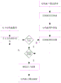
FIG. 4 is a flow chart of the composite structural panel of the present invention;
fig. 5 is a flow of information for a composite structural panel in accordance with the present invention.
Detailed Description
The invention is described in detail below by way of example with reference to the accompanying drawings.
The embodiment provides a method for rapidly manufacturing a composite material structural plate, as shown in fig. 2, hardware and software are adopted, the hardware comprises a computer, a calibration plate, an industrial camera and a projector, and the main body of the software adopts Pro/E.
And the computer on the production site is used for displaying the composite material structural plate model, running software and connecting hardware, configuring Pro/E secondary development composite material structural plate auxiliary manufacturing software and connecting the Pro/E secondary development composite material structural plate auxiliary manufacturing software with an industrial camera and a projector in place.
The industrial camera is used for acquiring the object image information of the structural plate lower skin and the target on the field workbench and processing the object image by using image recognition.
The projector is used for outputting the image processed in the computer to the surface of the real object.
As shown in fig. 3, the Pro/E based secondary development composite structural panel assisted manufacturing software comprises five modules: the system comprises a calibration module, a real object image acquisition module, a model image acquisition module, an image matching and transformation module and an image output module;
the calibration module is used for calibrating a transformation matrix among the industrial camera, the calibration plate and the projector based on the calibration plate, so as to ensure that the real object image information acquired by the industrial camera is completely coincided with the calibration plate after being transformed, and the calibration plate modeling image after being inversely transformed is coincided with the real object of the calibration plate after being put by the projector;
the object image acquisition module is used for identifying target information of the surface of an object;
the model image acquisition module is used for extracting image information in the three-dimensional model of the structural plate and identifying target information in the model image of the structural plate;
the image matching and converting module is used for carrying out distortion processing on the lower skin real object image and the structural plate model image and matching target information in the structural plate model image and the lower skin real object image;
the image output module is used for outputting the processed structural slab model image to the surface of a real object, so that the target position of the output structural slab model image is ensured to be coincident with the target position of the real object, and the position of the embedded part is coincident with the position of the lower skin opening of the structural slab.
As shown in fig. 4 and 5, the composite material structural panel is manufactured by the following steps:
firstly, placing a lower skin of a perforated structural slab in place on a workbench, and then installing a target in place;
secondly, coating a glue layer on the lower skin of the structural slab according to the process requirements;
and step three, according to the technological requirements, completely sleeving the embedded parts of the structural slab.
Acquiring a skin real object image under the structural plate by using an industrial camera, and identifying target information of the surface of the skin real object by using a real object image acquisition module;
opening the three-dimensional model of the structural slab by using Pro/E software, setting the background color to be white, improving the contrast, and identifying target information in the model image of the structural slab by using a model image acquisition module;
a calibration module is adopted to obtain a transformation matrix among the industrial camera, the calibration plate and the projector in advance, an image matching and transformation module carries out distortion processing on the lower skin object image and the structural plate model image by utilizing the transformation matrix, and then target information in the structural plate model image and the lower skin object image are matched;
fifthly, selecting embedded parts of the same type to be installed in batches by using a model tree or a filtering function;
step six, the image output module projects the processed model image of the structural plate to the surface of a real object through a projector, model information is displayed on the surface of the real object at a ratio of 1:1, the target position of the projected model image of the structural plate is ensured to coincide with the target position of the real object of the lower skin, and the position of an embedded part coincides with the hole opening position of the lower skin of the structural plate;
seventhly, placing the embedded parts of the structural slab according to the model information displayed on the surface of the structural slab; checking whether other types of embedded parts exist, if so, projecting the structural plate model image to the surface of the real object again through the projector, displaying model information on the surface of the real object in a ratio of 1:1, and installing other types of embedded parts according to the displayed model information; if not, carrying out the next operation;
step eight, after all embedded parts are placed, placing the honeycomb cores;
and step nine, assembling the skin on the structural slab according to the process requirements.
After the composite material structural plate is assembled, the method can be continuously adopted to implement or check the thermal control paint spraying, the pin sticking and the heating plate sticking.
In summary, the above description is only a preferred embodiment of the present invention, and is not intended to limit the scope of the present invention. Any modification, equivalent replacement, or improvement made within the spirit and principle of the present invention should be included in the protection scope of the present invention.
Claims (5)
1. A method for rapidly manufacturing a composite material structural panel, characterized in that the manufacturing method comprises the following steps:
firstly, placing a lower skin of a perforated structural slab in place on a workbench, then installing a target in place, and coating a glue layer on the lower skin;
calibrating a transformation matrix among the industrial camera, the calibration plate and the projector through the calibration plate to ensure that the real object image information acquired by the industrial camera is completely coincided with the calibration plate after being transformed, and the calibration plate modeling image after being inversely transformed is coincided with the real object of the calibration plate after being released by the projector;
acquiring a skin real object image under the structural plate by using an industrial camera, and identifying target information on the surface of the lower skin by using software;
opening the three-dimensional model of the structural slab by using software, and identifying target information in the structural slab model image; distortion processing is carried out on the lower skin object image and the structural plate model image, and target information in the structural plate model image and the lower skin object image is matched;
projecting the processed structural plate model image to the surface of a lower skin real object through a projector, ensuring that the target position of the projected structural plate model image is coincided with the target position of the lower skin real object, and the embedded part position is coincided with the lower skin hole opening position of the structural plate;
and step four, assembling the material object embedded part, the honeycomb core and the structural plate upper skin in sequence.
2. The method for rapidly manufacturing the composite material structural plate as claimed in claim 1, wherein the specific method of the distortion treatment in the second step is as follows: the transformation matrix is used for transforming the lower skin real object image, so that the distortion of an industrial camera is eliminated; and calculating a distortion matrix between the structural plate model image and the lower skin real object image, and reprocessing the structural plate model image by using the distortion inverse matrix.
3. The method for rapidly manufacturing the composite material structural panel according to claim 1, wherein the software is based on secondary development composite material structural panel auxiliary manufacturing software, and comprises five modules, which are respectively: the system comprises a calibration module, a real object image acquisition module, a model image acquisition module, an image matching and transformation module and an image output module;
the calibration module is used for calibrating a transformation matrix among the industrial camera, the calibration plate and the projector based on the calibration plate, so as to ensure that the real object image information acquired by the industrial camera is completely coincided with the calibration plate after being transformed, and the calibration plate modeling image after being inversely transformed is coincided with the real object of the calibration plate after being put by the projector;
the object image acquisition module is used for identifying target information of the surface of the lower skin object;
the model image acquisition module is used for extracting image information in the three-dimensional model of the structural plate and identifying target information in the model image of the structural plate;
the image matching and converting module is used for carrying out distortion processing on the lower skin real object image and the structural plate model image and matching target information in the structural plate model image and the lower skin real object image;
the image output module is used for outputting the processed structural plate model image to the surface of the lower skin real object, so that the target position of the output structural plate model image is ensured to be coincident with the real object target position, and the embedded part position is coincident with the hole opening position of the lower skin of the structural plate.
4. A composite structural panel rapid manufacturing assistance system, the manufacturing assistance system comprising a computer, an industrial camera, and a projector;
the computer is used for displaying a composite material structural plate model, running software and connecting hardware, configuring Pro/E secondary development composite material structural plate auxiliary manufacturing software and connecting the Pro/E secondary development composite material structural plate auxiliary manufacturing software with an industrial camera and a projector in place;
the industrial camera is used for acquiring the object image information of the structural plate lower skin and the target on the field workbench;
the secondary development composite material structural plate auxiliary manufacturing software is used for extracting a real object image and a model image, matching the real object image and the model image by means of set target information, and outputting the model image to a projector; calibrating a transformation matrix among the industrial camera, the calibration plate and the projector based on the calibration plate to ensure that the real object image information acquired by the industrial camera is completely coincided with the calibration plate after being transformed, and the calibration plate modeling image after being inversely transformed is coincided with the real object of the calibration plate after being released by the projector;
the projector is used for outputting the model image to the surface of a real object and displaying the installation position of the embedded part on the real object of the structural plate.
5. The composite structural panel rapid manufacturing auxiliary system of claim 4, wherein the secondary development composite structural panel auxiliary manufacturing software comprises five modules, respectively: the system comprises a calibration module, a real object image acquisition module, a model image acquisition module, an image matching and transformation module and an image output module;
the calibration module is used for calibrating a transformation matrix among the industrial camera, the calibration plate and the projector based on the calibration plate, so as to ensure that the real object image information acquired by the industrial camera is completely coincided with the calibration plate after being transformed, and the calibration plate modeling image after being inversely transformed is coincided with the real object of the calibration plate after being put by the projector;
the object image acquisition module is used for identifying target information of the surface of an object;
the model image acquisition module is used for extracting image information in the three-dimensional model of the structural plate and identifying target information in the model image of the structural plate;
the image matching and converting module is used for carrying out distortion processing on the lower skin real object image and the model image and matching target information in the structural plate model image and the lower skin real object image;
the image output module is used for outputting the processed structural slab model image to the surface of a real object, so that the target position of the output structural slab model image is ensured to be coincident with the target position of the real object, and the position of the embedded part is coincident with the position of the lower skin opening of the structural slab.
Priority Applications (1)
| Application Number | Priority Date | Filing Date | Title |
|---|---|---|---|
| CN201910294597.8A CN110077093B (en) | 2019-04-12 | 2019-04-12 | Rapid manufacturing method and auxiliary manufacturing system for composite material structural plate |
Applications Claiming Priority (1)
| Application Number | Priority Date | Filing Date | Title |
|---|---|---|---|
| CN201910294597.8A CN110077093B (en) | 2019-04-12 | 2019-04-12 | Rapid manufacturing method and auxiliary manufacturing system for composite material structural plate |
Publications (2)
| Publication Number | Publication Date |
|---|---|
| CN110077093A CN110077093A (en) | 2019-08-02 |
| CN110077093B true CN110077093B (en) | 2021-02-12 |
Family
ID=67414986
Family Applications (1)
| Application Number | Title | Priority Date | Filing Date |
|---|---|---|---|
| CN201910294597.8A Active CN110077093B (en) | 2019-04-12 | 2019-04-12 | Rapid manufacturing method and auxiliary manufacturing system for composite material structural plate |
Country Status (1)
| Country | Link |
|---|---|
| CN (1) | CN110077093B (en) |
Families Citing this family (1)
| Publication number | Priority date | Publication date | Assignee | Title |
|---|---|---|---|---|
| CN111774616B (en) * | 2020-06-30 | 2023-09-12 | 中航成飞民用飞机有限责任公司 | Three-dimensional projection auxiliary assembly fixture |
Family Cites Families (12)
| Publication number | Priority date | Publication date | Assignee | Title |
|---|---|---|---|---|
| CN101468533B (en) * | 2007-12-25 | 2012-11-28 | 上海卫星工程研究所 | Spacecraft magnesium alloy insert board |
| CN102649376B (en) * | 2011-06-21 | 2014-04-02 | 北京京东方光电科技有限公司 | Titling method and equipment |
| JP5806013B2 (en) * | 2011-06-28 | 2015-11-10 | 旭化成ホームズ株式会社 | Design system |
| KR101288069B1 (en) * | 2011-11-14 | 2013-07-18 | 현대모비스 주식회사 | Parking assistance system using projector and method thereof |
| CN102801994B (en) * | 2012-06-19 | 2014-08-20 | 西北工业大学 | Physical image information fusion device and method |
| CN102810205B (en) * | 2012-07-09 | 2015-08-05 | 深圳泰山在线科技有限公司 | The scaling method of a kind of shooting or photographic means |
| DE102013113075A1 (en) * | 2013-11-26 | 2015-05-28 | Denso Corporation | Fuel filter for ECU cooling |
| CN106777498B (en) * | 2016-11-18 | 2020-10-09 | 上海卫星工程研究所 | Method for quickly creating three-dimensional model of honeycomb sandwich plate |
| CN106503403A (en) * | 2016-11-29 | 2017-03-15 | 上海卫星工程研究所 | A 3D labeling method for satellite honeycomb sandwich panels |
| CN107230250B (en) * | 2017-04-14 | 2024-03-19 | 郭中献 | Forming method for direct three-dimensional modeling by referring to solid specimen |
| CN107609209B (en) * | 2017-07-27 | 2020-07-14 | 上海卫星工程研究所 | Rapid design method for satellite honeycomb sandwich plate connection embedded part |
| CN108489381A (en) * | 2017-12-28 | 2018-09-04 | 渤海造船厂集团有限公司 | A kind of ship fast accurate trepanning localization method |
-
2019
- 2019-04-12 CN CN201910294597.8A patent/CN110077093B/en active Active
Also Published As
| Publication number | Publication date |
|---|---|
| CN110077093A (en) | 2019-08-02 |
Similar Documents
| Publication | Publication Date | Title |
|---|---|---|
| EP2524329B1 (en) | Assembly and method for verifying a real model using a virtual model and use in aircraft construction | |
| US12505758B2 (en) | Method for testing a connectorized electrical equipment in an environment | |
| EP2575147B1 (en) | Workbench for manufacturing or checking electrical wiring harnesses | |
| CN109676280A (en) | Auto-body manufacturing generalization system and Auto-body manufacturing generalization intelligent plant system | |
| CN106777498B (en) | Method for quickly creating three-dimensional model of honeycomb sandwich plate | |
| JP7060475B2 (en) | Automatic rivet measurement system | |
| US20060155402A1 (en) | 3d virtual manufacturing process | |
| CN107133876A (en) | Car damage identification method and setting loss client | |
| CN102147607A (en) | Flexible general production line and production method of electronic product | |
| US4961148A (en) | Method for preparing automotive assembly operations documents | |
| CN104123412A (en) | Method for detecting collision of curtain wall through BIM technology | |
| CN110717212B (en) | BIM (building information modeling) model checking method | |
| CN109919512B (en) | A spacecraft final assembly management system | |
| CN109657376B (en) | Full-vehicle automatic modeling method for CAE simulation | |
| CN107330178A (en) | Based on Pro/E spacecraft technique digital prototype automatic build systems | |
| CN107992670A (en) | The simulation matching process of auto parts and components | |
| CN110077093B (en) | Rapid manufacturing method and auxiliary manufacturing system for composite material structural plate | |
| CN106503403A (en) | A 3D labeling method for satellite honeycomb sandwich panels | |
| EP3382654B1 (en) | Method for virtually inspecting an actual produced part | |
| CN118153365A (en) | Assembled concrete structure forward design method based on BIM technology | |
| Ma et al. | Efficient and effective dimension control in automotive applications | |
| CN106354943A (en) | Engineering modularized manufacturing system and engineering modularized manufacturing method | |
| US20020122581A1 (en) | Method and apparatus for utilizing representational images in commercial and other activities | |
| Toriya | 3D manufacturing innovation: revolutionary change in Japanese manufacturing with digital data | |
| US9982986B2 (en) | System and method for creating and utilizing a construction aid |
Legal Events
| Date | Code | Title | Description |
|---|---|---|---|
| PB01 | Publication | ||
| PB01 | Publication | ||
| SE01 | Entry into force of request for substantive examination | ||
| SE01 | Entry into force of request for substantive examination | ||
| GR01 | Patent grant | ||
| GR01 | Patent grant |