CN110035789B - patient interface - Google Patents
patient interface Download PDFInfo
- Publication number
- CN110035789B CN110035789B CN201780073731.0A CN201780073731A CN110035789B CN 110035789 B CN110035789 B CN 110035789B CN 201780073731 A CN201780073731 A CN 201780073731A CN 110035789 B CN110035789 B CN 110035789B
- Authority
- CN
- China
- Prior art keywords
- frame
- mask
- configurations
- headgear
- seal
- Prior art date
- Legal status (The legal status is an assumption and is not a legal conclusion. Google has not performed a legal analysis and makes no representation as to the accuracy of the status listed.)
- Active
Links
Images


Classifications
-
- A—HUMAN NECESSITIES
- A61—MEDICAL OR VETERINARY SCIENCE; HYGIENE
- A61M—DEVICES FOR INTRODUCING MEDIA INTO, OR ONTO, THE BODY; DEVICES FOR TRANSDUCING BODY MEDIA OR FOR TAKING MEDIA FROM THE BODY; DEVICES FOR PRODUCING OR ENDING SLEEP OR STUPOR
- A61M16/00—Devices for influencing the respiratory system of patients by gas treatment, e.g. ventilators; Tracheal tubes
- A61M16/06—Respiratory or anaesthetic masks
- A61M16/0605—Means for improving the adaptation of the mask to the patient
- A61M16/0616—Means for improving the adaptation of the mask to the patient with face sealing means comprising a flap or membrane projecting inwards, such that sealing increases with increasing inhalation gas pressure
-
- A—HUMAN NECESSITIES
- A61—MEDICAL OR VETERINARY SCIENCE; HYGIENE
- A61M—DEVICES FOR INTRODUCING MEDIA INTO, OR ONTO, THE BODY; DEVICES FOR TRANSDUCING BODY MEDIA OR FOR TAKING MEDIA FROM THE BODY; DEVICES FOR PRODUCING OR ENDING SLEEP OR STUPOR
- A61M16/00—Devices for influencing the respiratory system of patients by gas treatment, e.g. ventilators; Tracheal tubes
- A61M16/06—Respiratory or anaesthetic masks
- A61M16/0605—Means for improving the adaptation of the mask to the patient
- A61M16/0611—Means for improving the adaptation of the mask to the patient with a gusset portion
-
- A—HUMAN NECESSITIES
- A61—MEDICAL OR VETERINARY SCIENCE; HYGIENE
- A61M—DEVICES FOR INTRODUCING MEDIA INTO, OR ONTO, THE BODY; DEVICES FOR TRANSDUCING BODY MEDIA OR FOR TAKING MEDIA FROM THE BODY; DEVICES FOR PRODUCING OR ENDING SLEEP OR STUPOR
- A61M16/00—Devices for influencing the respiratory system of patients by gas treatment, e.g. ventilators; Tracheal tubes
- A61M16/06—Respiratory or anaesthetic masks
- A61M16/0683—Holding devices therefor
-
- A—HUMAN NECESSITIES
- A61—MEDICAL OR VETERINARY SCIENCE; HYGIENE
- A61M—DEVICES FOR INTRODUCING MEDIA INTO, OR ONTO, THE BODY; DEVICES FOR TRANSDUCING BODY MEDIA OR FOR TAKING MEDIA FROM THE BODY; DEVICES FOR PRODUCING OR ENDING SLEEP OR STUPOR
- A61M16/00—Devices for influencing the respiratory system of patients by gas treatment, e.g. ventilators; Tracheal tubes
- A61M16/08—Bellows; Connecting tubes ; Water traps; Patient circuits
- A61M16/0816—Joints or connectors
-
- A—HUMAN NECESSITIES
- A61—MEDICAL OR VETERINARY SCIENCE; HYGIENE
- A61M—DEVICES FOR INTRODUCING MEDIA INTO, OR ONTO, THE BODY; DEVICES FOR TRANSDUCING BODY MEDIA OR FOR TAKING MEDIA FROM THE BODY; DEVICES FOR PRODUCING OR ENDING SLEEP OR STUPOR
- A61M16/00—Devices for influencing the respiratory system of patients by gas treatment, e.g. ventilators; Tracheal tubes
- A61M16/20—Valves specially adapted to medical respiratory devices
- A61M16/208—Non-controlled one-way valves, e.g. exhalation, check, pop-off non-rebreathing valves
-
- A—HUMAN NECESSITIES
- A61—MEDICAL OR VETERINARY SCIENCE; HYGIENE
- A61M—DEVICES FOR INTRODUCING MEDIA INTO, OR ONTO, THE BODY; DEVICES FOR TRANSDUCING BODY MEDIA OR FOR TAKING MEDIA FROM THE BODY; DEVICES FOR PRODUCING OR ENDING SLEEP OR STUPOR
- A61M2210/00—Anatomical parts of the body
- A61M2210/06—Head
- A61M2210/0618—Nose
-
- A—HUMAN NECESSITIES
- A61—MEDICAL OR VETERINARY SCIENCE; HYGIENE
- A61M—DEVICES FOR INTRODUCING MEDIA INTO, OR ONTO, THE BODY; DEVICES FOR TRANSDUCING BODY MEDIA OR FOR TAKING MEDIA FROM THE BODY; DEVICES FOR PRODUCING OR ENDING SLEEP OR STUPOR
- A61M2210/00—Anatomical parts of the body
- A61M2210/06—Head
- A61M2210/0625—Mouth
Landscapes
- Health & Medical Sciences (AREA)
- Pulmonology (AREA)
- Emergency Medicine (AREA)
- Engineering & Computer Science (AREA)
- Anesthesiology (AREA)
- Biomedical Technology (AREA)
- Heart & Thoracic Surgery (AREA)
- Hematology (AREA)
- Life Sciences & Earth Sciences (AREA)
- Animal Behavior & Ethology (AREA)
- General Health & Medical Sciences (AREA)
- Public Health (AREA)
- Veterinary Medicine (AREA)
- Respiratory Apparatuses And Protective Means (AREA)
- Percussion Or Vibration Massage (AREA)
- Pharmaceuticals Containing Other Organic And Inorganic Compounds (AREA)
- Ultra Sonic Daignosis Equipment (AREA)
Abstract
一种面罩组件可以包括面罩密封件。在一些构型中,所述面罩组件可以被构造成完全低于使用者面部的鼻梁定位并且使所述使用者的所述鼻梁外露。所述面罩密封件可以包括鼻部区域,所述鼻部区域包括至少一个鼻部开口;第一翼片,所述第一翼片位于所述鼻部区域的第一侧上;以及第二翼片,所述第二翼片位于所述鼻部区域的第二侧上。所述第一翼片被构造成接触所述使用者的所述鼻部的一侧并且所述第二翼片被构造成接触所述使用者的所述鼻部的另一侧。
A mask assembly may include a mask seal. In some configurations, the mask assembly may be configured to be positioned well below the bridge of the nose of the user's face and to expose the bridge of the nose of the user. The mask seal may include a nasal region including at least one nasal opening; a first fin on a first side of the nasal region; and a second fin the second fin is located on the second side of the nose region. The first fin is configured to contact one side of the user's nose and the second fin is configured to contact the other side of the user's nose.
Description
通过援引并入任何优先权申请Incorporate by reference any priority application
本申请要求2016年10月5日提交的美国临时申请号62/413,604、2017年10月26日提交的美国临时申请号62/413,280、和2016年10月27日提交的美国临时申请号62/404,341的优先权,所述申请中的每一个通过援引以其全文并入本文。This application claims US Provisional Application No. 62/413,604, filed October 5, 2016, US Provisional Application No. 62/413,280, filed October 26, 2017, and US Provisional Application No. 62/, filed October 27, 2016 404,341, each of which is hereby incorporated by reference in its entirety.
发明背景Background of the Invention
技术领域technical field
本披露内容涉及用于呼吸疗法的接口组件。具体地,本披露内容涉及不覆盖使用者鼻梁的鼻下接口组件。The present disclosure relates to interface assemblies for respiratory therapy. In particular, the present disclosure relates to sub-nasal interface assemblies that do not cover the bridge of a user's nose.
背景技术Background technique
在患有阻塞性睡眠呼吸暂停(OSA)的患者中,正常保持上呼吸道打开的肌肉在睡眠过程中松弛达到使气道受到约束或完全封闭的程度,即自身通常以打鼾的形式表现的现象。当这种情况发生持续一段时间时,患者的大脑典型地意识到缺氧威胁并且不完全地唤醒患者以便打开气道,使得可以恢复正常呼吸。患者可能没有意识到这些唤醒事件,这些唤醒事件在每个睡眠期间可能发生多达数百次。这种不完全唤醒会显著地降低患者的睡眠质量,从而随着时间的推移而潜在地导致多种症状,包括日间过度嗜睡、慢性疲劳、心率升高、血压升高、体重增加、头痛、易怒、抑郁以及焦虑。In patients with obstructive sleep apnea (OSA), the muscles that normally keep the upper airway open relax during sleep to the point that the airway becomes constrained or completely closed, a phenomenon that itself often manifests itself in the form of snoring. When this occurs for a period of time, the patient's brain typically becomes aware of the hypoxia threat and does not fully awaken the patient to open the airway so that normal breathing can resume. Patients may be unaware of these arousal events, which can occur as many as hundreds of times during each sleep period. This incomplete arousal can significantly reduce a patient's sleep quality, potentially leading to a variety of symptoms over time, including excessive daytime sleepiness, chronic fatigue, increased heart rate, increased blood pressure, weight gain, headaches, Irritability, depression, and anxiety.
阻塞性睡眠呼吸暂停常常通过应用气道正压通气(PAP)疗法加以治疗。PAP疗法涉及在高于大气压的治疗压力下向患者递送气体流,这将会降低呼吸暂停、呼吸不足、和/或流动受限的频率和/或持续时间。该疗法通常通过以下方式来实现:使用气道正压通气装置通过导管递送加压空气流以穿过定位在患者面部上的患者接口或面罩而到达患者。Obstructive sleep apnea is often treated with the use of positive airway pressure (PAP) therapy. PAP therapy involves delivering a flow of gas to the patient at a therapeutic pressure above atmospheric pressure, which will reduce the frequency and/or duration of apnea, hypopnea, and/or flow restriction. This therapy is typically accomplished by delivering a flow of pressurized air through a catheter using a positive airway pressure device to reach the patient through a patient interface or mask positioned on the patient's face.
一种用于与PAP疗法或者涉及气体给予的其他呼吸疗法一起使用的常见类型的患者接口组件包括密封件,该密封件接触接口组件的使用者的鼻梁。鼻梁对由接口组件的密封件施加的压力敏感。最近,不接触鼻梁的接口组件已经可供使用。此类接口组件可以被称为“鼻下”接口组件。需要提供具有改善舒适度和/或密封性能的改进的鼻下接口组件,或者需要向公众提供有用的选择。One common type of patient interface assembly for use with PAP therapy or other respiratory therapy involving gas administration includes a seal that contacts the bridge of the nose of a user of the interface assembly. The bridge of the nose is sensitive to pressure applied by the seals of the interface assembly. More recently, interface assemblies that do not touch the bridge of the nose have become available. Such interface assemblies may be referred to as "under the nose" interface assemblies. There is a need to provide improved subnasal interface assemblies with improved comfort and/or sealing properties, or to provide the public with a useful choice.
发明内容SUMMARY OF THE INVENTION
本文所描述的系统、方法、和设备具有创新方面,其中没有单一方面是必不可少的或单独地能获得其期望属性。在不限制权利要求的范围的情况下,现在将概述有利特征中的一些有利特征。The systems, methods, and devices described herein have innovative aspects, no single one of which is essential or alone achieves its desired attributes. Without limiting the scope of the claims, some of the advantageous features will now be summarized.
在一些构型中,一种用于在提供正压呼吸疗法过程中使用的接口包括面罩组件,所述面罩组件具有面罩密封件。面罩组件被构造成完全低于使用者面部的鼻梁定位并且使得使用者的鼻梁外露。面罩密封件包括鼻部区域,所述鼻部区域包括至少一个鼻部开口。面罩密封件包括位于鼻部区域的第一侧上的第一翼片以及位于鼻部区域的第二侧上的第二翼片。第一翼片被构造成接触使用者鼻部的一侧并且第二翼片被构造成接触使用者鼻部的另一侧。第一翼片包括从第一翼片的前侧延伸到第一翼片的后侧的第一切口区域。第二翼片包括从第二翼片的前侧延伸到第二翼片的后侧的第二切口区域。In some configurations, an interface for use in providing positive pressure breathing therapy includes a mask assembly having a mask seal. The mask assembly is configured to be positioned well below the nasal bridge of the user's face and to expose the user's nasal bridge. The mask seal includes a nasal region including at least one nasal opening. The mask seal includes a first fin on a first side of the nasal region and a second fin on a second side of the nasal region. The first flap is configured to contact one side of the user's nose and the second flap is configured to contact the other side of the user's nose. The first flap includes a first cutout region extending from the front side of the first flap to the rear side of the first flap. The second flap includes a second cutout region extending from the front side of the second flap to the rear side of the second flap.
在一些构型中,面罩密封件进一步包括支撑结构,所述支撑结构被构造成支撑面罩密封件的鼻部区域。In some configurations, the mask seal further includes a support structure configured to support the nasal region of the mask seal.
在一些构型中,面罩密封件包括凹入前表面,所述凹入前表面包括被构造成接收框架翼片的上部凹入前表面。In some configurations, the mask seal includes a concave front surface including an upper concave front surface configured to receive a frame flap.
在一些构型中,第一切口区域包括减小的壁厚度。In some configurations, the first cutout region includes a reduced wall thickness.
在一些构型中,第一切口区域包括沿着第一切口区域的长度定位的第一凹面部分,并且第二切口区域包括沿着第二切口区域的长度定位的第二凹面部分。In some configurations, the first cutout region includes a first concave portion positioned along the length of the first cutout region, and the second cutout region includes a second concave portion positioned along the length of the second cutout region.
在一些构型中,第一凹面部分被构造成当向第一翼片施加力时允许第一切口区域向内折叠,并且第二凹面部分被构造成当向第二翼片施加力时允许第二切口区域向内折叠。In some configurations, the first concave portion is configured to allow the first cutout region to fold inward when a force is applied to the first flap, and the second concave portion is configured to allow the second flap to be applied with a force The second cut area is folded inward.
在一些构型中,面罩密封件包括沿着面罩密封件的外周侧定位的凹面区域。In some configurations, the mask seal includes a concave region located along a peripheral side of the mask seal.
在一些构型中,第一切口区域包括第一内部区域和第一外部区域。第一内部区域被构造成当向第一内部区域施加力时朝向第一外部区域压缩。第二切口区域包括第二内部区域和第二外部区域。第二内部区域被构造成当向第二外部区域施加力时朝向第二外部区域压缩。In some configurations, the first cutout region includes a first inner region and a first outer region. The first inner region is configured to compress toward the first outer region when a force is applied to the first inner region. The second cutout region includes a second inner region and a second outer region. The second inner region is configured to compress toward the second outer region when a force is applied to the second outer region.
在一些构型中,第一切口区域跨过第一翼片的后侧的一部分至少延伸到鼻部开口的第一侧。In some configurations, the first cutout region extends across a portion of the rear side of the first flap to at least the first side of the nasal opening.
在一些构型中,一种用于在提供正压呼吸疗法过程中使用的接口包括面罩组件,所述面罩组件具有面罩密封件。面罩组件被构造成完全低于使用者面部的鼻梁定位并且使得使用者的鼻梁外露。面罩密封件包括鼻部区域,所述鼻部区域包括至少一个鼻部开口。面罩密封件包括位于鼻部区域的第一侧上的第一翼片以及位于鼻部区域的第二侧上的第二翼片。第一翼片被构造成接触使用者鼻部的一侧并且第二翼片被构造成接触使用者鼻部的另一侧。面罩组件进一步包括前上部分。前上部分包括前凹入部分。在一些构型中,面罩组件进一步包括在前上部分的上周边与前凹入部分之间的台阶式过渡。In some configurations, an interface for use in providing positive pressure breathing therapy includes a mask assembly having a mask seal. The mask assembly is configured to be positioned well below the nasal bridge of the user's face and to expose the user's nasal bridge. The mask seal includes a nasal region including at least one nasal opening. The mask seal includes a first fin on a first side of the nasal region and a second fin on a second side of the nasal region. The first flap is configured to contact one side of the user's nose and the second flap is configured to contact the other side of the user's nose. The mask assembly further includes an upper front portion. The front upper portion includes a front concave portion. In some configurations, the mask assembly further includes a stepped transition between the upper perimeter of the upper front portion and the front recessed portion.
在一些构型中,台阶式过渡遵循第一翼片和第二翼片的周边的曲率。In some configurations, the stepped transition follows the curvature of the perimeter of the first and second fins.
在一些构型中,台阶式过渡在深度上变化。In some configurations, the stepped transition varies in depth.
在一些构型中,台阶式过渡是渐缩的,使得深度在台阶式过渡的下部末端处最小。In some configurations, the stepped transition is tapered such that the depth is minimal at the lower end of the stepped transition.
在一些构型中,台阶式过渡的深度取决于面罩密封件的大小。In some configurations, the depth of the stepped transition depends on the size of the mask seal.
在一些构型中,面罩组件进一步包括框架。前凹入部分被构造成接收框架的至少一部分。In some configurations, the mask assembly further includes a frame. The front recessed portion is configured to receive at least a portion of the frame.
在一些构型中,台阶式过渡的最大深度大于或等于框架的厚度。In some configurations, the maximum depth of the stepped transition is greater than or equal to the thickness of the frame.
在一些构型中,前上部分进一步包括在第一翼片和第二翼片的前侧上形成的第一上部拐角和第二上部拐角。In some configurations, the upper front portion further includes first and second upper corners formed on the front sides of the first and second fins.
在一些构型中,台阶式过渡包括变化的深度,使得台阶式过渡的深度在第一上部拐角和第二上部拐角处比在第一上部拐角与第二上部拐角之间的中间部分处更大。In some configurations, the stepped transition includes varying depths such that the depth of the stepped transition is greater at the first and second upper corners than at an intermediate portion between the first and second upper corners .
在一些构型中,接口包括可移除地连接至面罩组件的框架。In some configurations, the interface includes a frame that is removably connected to the mask assembly.
在一些构型中,框架包括框架翼片。In some configurations, the frame includes frame tabs.
在一些构型中,当组装到面罩组件时,框架翼片定位成插入和/或在前凹入表面内。In some configurations, the frame flaps are positioned to be inserted and/or within the front concave surface when assembled to the mask assembly.
在一些构型中,框架翼片的外表面与上凹入表面齐平。In some configurations, the outer surface of the frame tab is flush with the upper concave surface.
在一些构型中,框架为密封件的鼻部区域提供额外的支撑。In some configurations, the frame provides additional support for the nose region of the seal.
在一些构型中,框架为密封件的前侧鼻部区域提供额外的刚性。In some configurations, the frame provides additional rigidity to the front nose region of the seal.
在一些构型中,框架翼片为鼻部区域提供支撑。In some configurations, the frame flaps provide support for the nasal region.
在一些构型中,框架翼片有助于防止密封翼片在使用中远离使用者的鼻部偏转。In some configurations, the frame flaps help prevent the sealing flaps from deflecting away from the user's nose in use.
在一些构型中,框架翼片可以有助于在面罩密封件变得过度变形的情况下防止框架翼片接触或挖入使用者的面部中。In some configurations, the frame flaps may help prevent the frame flaps from contacting or digging into the user's face if the mask seal becomes excessively deformed.
在一些构型中,凹入的前表面允许单一大小的框架与具有不同大小的面罩组件一起实施的用途。In some configurations, the concave front surface allows the use of a single sized frame to be implemented with mask assemblies having different sizes.
根据一些实施例,一种用于在提供正压呼吸疗法过程中使用的接口可以包括面罩组件和框架。面罩组件可以包括面罩密封件。面罩组件可以完全低于使用者面部的鼻梁定位并且使得使用者的鼻梁外露。面罩密封件可以包括鼻部区域。鼻部区域可以包括至少一个鼻部开口。面罩密封件可以包括位于鼻部区域的第一侧上的第一翼片以及位于鼻部区域的第二侧上的第二翼片。第一翼片可以接触使用者鼻部的一侧,并且第二翼片可以接触使用者鼻部的另一侧。框架可以可移除地联接至面罩组件。面罩组件可以包括外壳。外壳可以包括入口和围绕入口的凹面前表面。入口可以限定通向面罩组件的内部腔室的流动路径。According to some embodiments, an interface for use in providing positive pressure breathing therapy may include a mask assembly and a frame. The mask assembly may include a mask seal. The mask assembly may be positioned well below the bridge of the nose of the user's face and expose the bridge of the user's nose. The mask seal may include the nasal region. The nasal region may include at least one nasal opening. The mask seal may include a first fin on a first side of the nasal region and a second fin on a second side of the nasal region. The first flap may contact one side of the user's nose and the second flap may contact the other side of the user's nose. The frame may be removably coupled to the mask assembly. The mask assembly can include a housing. The housing may include an inlet and a concave front surface surrounding the inlet. The inlet may define a flow path to the interior chamber of the mask assembly.
在一些构型中,接口包括通过连接特征连接至框架的弯管。In some configurations, the interface includes an elbow connected to the frame by a connection feature.
在一些构型中,连接特征包括卡扣配合安排,使得框架可以卡入弯管的狭槽中。In some configurations, the connection feature includes a snap fit arrangement such that the frame can snap into the slot of the elbow.
在一些构型中,连接特征包括卡扣配合安排,使得弯管包括从弯管向外延伸的多个肋。多个肋可以形成狭槽以接收框架。In some configurations, the connection feature includes a snap fit arrangement such that the elbow includes a plurality of ribs extending outwardly from the elbow. The plurality of ribs may form slots to receive the frame.
在一些构型中,框架被成形为至少部分地接收弯管。In some configurations, the frame is shaped to at least partially receive the elbow.
在一些构型中,弯管包括阀口,所述阀口被构造成提供从大气到弯管的内部空间的流动路径。In some configurations, the elbow includes a valve port configured to provide a flow path from the atmosphere to the interior space of the elbow.
在一些构型中,阀口面向凹面前表面,并且阀口和凹面前表面限定流动路径,使得阀口的区域形成流动路径的最小区域。In some configurations, the valve port faces the concave front surface, and the valve port and the concave front surface define the flow path such that the area of the valve port forms the smallest area of the flow path.
在一些构型中,面罩组件可以包括偏置通气口,所述偏置通气口被构造成排出使用者呼出的空气。In some configurations, the mask assembly may include an offset vent configured to expel air exhaled by the user.
在一些构型中,一种用于在提供正压呼吸疗法过程中使用的接口包括面罩组件,所述面罩组件具有面罩密封件。面罩组件被构造成完全低于使用者面部的鼻梁定位并且使得使用者的鼻梁外露。面罩密封件包括鼻部区域,所述鼻部区域包括至少一个鼻部开口。面罩密封件包括位于鼻部区域的第一侧上的第一翼片以及位于鼻部区域的第二侧上的第二翼片。第一翼片被构造成接触使用者鼻部的一侧并且第二翼片被构造成接触使用者鼻部的另一侧。面罩组件进一步包括框架,所述框架可移除地联接至面罩组件,其中框架包括夹具保持特征,所述夹具保持特征被构造成连接至头戴具夹具。头戴具夹具包括:上绑带狭槽;下绑带狭槽;拉片;以及孔口,所述孔口定位在上绑带狭槽和下绑带狭槽的横向侧与拉片之间。In some configurations, an interface for use in providing positive pressure breathing therapy includes a mask assembly having a mask seal. The mask assembly is configured to be positioned well below the nasal bridge of the user's face and to expose the user's nasal bridge. The mask seal includes a nasal region including at least one nasal opening. The mask seal includes a first fin on a first side of the nasal region and a second fin on a second side of the nasal region. The first flap is configured to contact one side of the user's nose and the second flap is configured to contact the other side of the user's nose. The mask assembly further includes a frame removably coupled to the mask assembly, wherein the frame includes a clip retention feature configured to connect to the headgear clip. The headgear clip includes: an upper strap slot; a lower strap slot; a pull tab; and an aperture positioned between lateral sides of the upper and lower strap slots and the pull tab .
在一些构型中,夹具保持特征提供开口,所述开口被构造成排出使用者呼出的空气。In some configurations, the clip retention feature provides an opening configured to expel air exhaled by the user.
在一些构型中,头戴具夹具包括插入件,使得拉片形成包覆模制安排的至少一部分。In some configurations, the headgear clip includes an insert such that the pull tab forms at least part of an overmolded arrangement.
在一些构型中,框架包括键合凸起,所述键合凸起被构造成接合头戴具夹具的相应的键合凹口。In some configurations, the frame includes keying protrusions configured to engage corresponding keying recesses of the headgear clip.
在一些构型中,键合凸起定位在第一夹具保持特征的一侧上,并且键合凸起被构造成指示用于连接头戴具夹具的正确取向。In some configurations, the keying protrusions are positioned on one side of the first clip retention feature, and the keying protrusions are configured to indicate the correct orientation for connecting the headgear clip.
在一些构型中,框架包括至少两个开口。In some configurations, the frame includes at least two openings.
在一些构型中,头戴具夹具包括手指抓握部和拇指抓握部,手指抓握部和拇指抓握部形成提供给使用者的包覆模制的抓握部,其中手指抓握部沿着头戴具夹具的外凹表面与拇指抓握部横向相对地定位。In some configurations, the headgear clip includes a finger grip and a thumb grip that form an overmolded grip provided to the user, wherein the finger grip Positioned laterally opposite the thumb grip along the outer concave surface of the headgear clip.
在一些构型中,头戴具夹具邻近面罩密封件的前上部分定位,使得头戴具夹具防止面罩密封件膨胀。In some configurations, the headgear clip is positioned adjacent the upper front portion of the mask seal such that the headgear clip prevents expansion of the mask seal.
根据一些实施例,一种呼吸面罩可以包括面罩组件和框架。面罩组件可以包括密封件和外壳。密封件可以包括鼻部密封部分和口部密封部分。密封件可以为使用者的鼻部和嘴部提供气体流。外壳和密封件可以形成呼吸腔室。框架可以可移除地联接至面罩组件。框架可以包括:主体;入口开口,通过所述入口开口向面罩组件提供加压空气供应;以及防窒息阀,所述防窒息阀与入口开口流体连通。框架的主体可以限定防窒息阀的气体流动通道的至少一部分。According to some embodiments, a respiratory mask may include a mask assembly and a frame. The mask assembly may include a seal and a housing. The seal may include a nasal sealing portion and an oral sealing portion. The seal may provide a flow of gas to the nose and mouth of the user. The housing and seal may form a breathing chamber. The frame may be removably coupled to the mask assembly. The frame may include: a body; an inlet opening through which a supply of pressurized air is provided to the mask assembly; and an anti-asphyxia valve in fluid communication with the inlet opening. The body of the frame may define at least a portion of the gas flow passage of the anti-asphyxia valve.
在一些构型中,框架包括联接至框架的主体的管连接器。框架可以连接至呼吸管。管连接器可以限定入口开口。In some configurations, the frame includes a tube connector coupled to the body of the frame. The frame can be connected to a breathing tube. The tube connector may define an inlet opening.
在一些构型中,管连接器可以将防窒息阀的阀构件固定至框架的主体。In some configurations, a tube connector may secure the valve member of the anti-asphyxia valve to the body of the frame.
在一些构型中,框架可以限定面罩连接器。面罩连接器可以将面罩组件固定至框架。面罩连接器可以限定气体流动通道的一部分。面罩连接器可以接收来自入口开口和防窒息阀的气体流。面罩连接器可以将气体流输送到面罩组件。In some configurations, the frame may define a mask connector. The mask connector can secure the mask assembly to the frame. The mask connector may define a portion of the gas flow channel. The mask connector can receive gas flow from the inlet opening and the anti-asphyxia valve. The mask connector can deliver the flow of gas to the mask assembly.
在一些构型中,框架的前壁可以限定呼吸面罩的气体流动通道的一部分。In some configurations, the front wall of the frame may define a portion of the gas flow channel of the respirator.
在一些构型中,外壳可以限定凹陷部,所述凹陷部容纳框架的包括防窒息阀的至少一部分。In some configurations, the housing can define a recess that accommodates at least a portion of the frame that includes the anti-asphyxia valve.
在一些构型中,鼻部密封部分可以包括左鼻部密封表面和右鼻部密封表面。最靠近密封件的鼻部开口的每个密封表面的内部部分可以是大致平坦的。In some configurations, the nasal sealing portion may include a left nasal sealing surface and a right nasal sealing surface. The inner portion of each sealing surface closest to the nose opening of the seal may be substantially flat.
在一些构型中,密封表面中的每一者的外部部分可以是弯曲的。外部部分的曲率半径可以在外部部分中的每一者内在后到前的方向上减小。In some configurations, the outer portion of each of the sealing surfaces may be curved. The radius of curvature of the outer portions may decrease in a rear-to-front direction within each of the outer portions.
在一些构型中,在左密封表面与右密封表面之间限定的角度可以在后到前的方向上增加。In some configurations, the angle defined between the left and right sealing surfaces may increase in a rear-to-front direction.
在一些构型中,面罩包括入口管,所述入口管限定气体流动通道的一部分并且相对于框架的主体固定。In some configurations, the mask includes an inlet tube that defines a portion of the gas flow channel and is fixed relative to the body of the frame.
在一些构型中,入口开口与框架的主体一体形成。In some configurations, the inlet opening is integrally formed with the body of the frame.
在一些构型中,入口管从前壁的底部区域向下延伸。In some configurations, the inlet tube extends downwardly from the bottom region of the front wall.
在一些构型中,入口管包括前表面,所述前表面与前壁的前表面限定连续表面。In some configurations, the inlet tube includes a front surface that defines a continuous surface with the front surface of the front wall.
在一些构型中,入口管至少部分地定位在前壁的后方。In some configurations, the inlet tube is positioned at least partially behind the front wall.
在一些构型中,入口管包括后内表面和前内表面。后内表面可以远离入口延伸并且可以朝向前内表面成角度。In some configurations, the inlet tube includes a rear inner surface and a front inner surface. The rear inner surface may extend away from the inlet and may be angled toward the front inner surface.
在一些构型中,凹陷部容纳入口管。In some configurations, the recess accommodates the inlet tube.
在一些构型中,外壳包括偏置通气口,所述偏置通气口定位在入口孔口的相反两侧上并且在外壳的前表面上位于框架的下方。偏置通气口可以在框架的下边缘下方排出空气。In some configurations, the housing includes offset vents positioned on opposite sides of the inlet aperture and below the frame on the front surface of the housing. Offset vents allow air to escape under the lower edge of the frame.
根据一些实施例,一种呼吸面罩可以包括面罩组件和框架。面罩组件可以包括全面罩密封件和外壳。外壳可以包括偏置通气口。框架可以将面罩组件连接至加压空气供应,并且可以包括限定至少一个头戴具连接器的主体。偏置通气口可以定位在入口孔口的相反两侧上并且在外壳的前表面上位于框架的下方,并且偏置通气口可以在框架的下边缘下方排出空气。框架可以限定防窒息阀的气体流动通道的至少一部分。According to some embodiments, a respiratory mask may include a mask assembly and a frame. The mask assembly may include a full face mask seal and a shell. The housing may include offset vents. The frame can connect the mask assembly to the pressurized air supply and can include a body defining at least one headgear connector. The offset vent can be positioned on opposite sides of the inlet aperture and below the frame on the front surface of the housing, and the offset vent can vent air below the lower edge of the frame. The frame may define at least a portion of the gas flow passage of the anti-asphyxia valve.
在一些构型中,框架可以限定防窒息阀的至少一个阀出口。In some configurations, the frame may define at least one valve outlet of the anti-asphyxia valve.
在一些构型中,框架包括联接至框架的主体的管连接器。框架可以连接至呼吸管。管连接器可以限定入口开口。In some configurations, the frame includes a tube connector coupled to the body of the frame. The frame can be connected to a breathing tube. The tube connector may define an inlet opening.
在一些构型中,管连接器可以将防窒息阀的阀构件固定至框架的主体。In some configurations, a tube connector may secure the valve member of the anti-asphyxia valve to the body of the frame.
在一些构型中,框架可以限定面罩连接器。面罩连接器可以将面罩组件固定至框架。面罩连接器可以限定气体流动通道的一部分。面罩连接器可以接收来自入口开口和防窒息阀的气体流。面罩连接器可以将气体流输送到面罩组件。In some configurations, the frame may define a mask connector. The mask connector can secure the mask assembly to the frame. The mask connector may define a portion of the gas flow channel. The mask connector can receive gas flow from the inlet opening and the anti-asphyxia valve. The mask connector can deliver the flow of gas to the mask assembly.
在一些构型中,框架的前壁可以限定呼吸面罩的气体流动通道的一部分。In some configurations, the front wall of the frame may define a portion of the gas flow channel of the respirator.
在一些构型中,外壳可以限定凹陷部,所述凹陷部容纳框架的包括防窒息阀的至少一部分。In some configurations, the housing can define a recess that accommodates at least a portion of the frame that includes the anti-asphyxia valve.
在一些构型中,鼻部密封部分可以包括左鼻部密封表面和右鼻部密封表面。最靠近密封件的鼻部开口的每个密封表面的内部部分可以是大致平坦的。In some configurations, the nasal sealing portion may include a left nasal sealing surface and a right nasal sealing surface. The inner portion of each sealing surface closest to the nose opening of the seal may be substantially flat.
在一些构型中,密封表面中的每一者的外部部分可以是弯曲的。外部部分的曲率半径可以在外部部分中的每一者内在后到前的方向上减小。In some configurations, the outer portion of each of the sealing surfaces may be curved. The radius of curvature of the outer portions may decrease in a rear-to-front direction within each of the outer portions.
在一些构型中,在左密封表面与右密封表面之间限定的角度可以在后到前的方向上增加。In some configurations, the angle defined between the left and right sealing surfaces may increase in a rear-to-front direction.
在一些构型中,面罩包括入口管,所述入口管限定气体流动通道的一部分并且相对于框架的主体固定。In some configurations, the mask includes an inlet tube that defines a portion of the gas flow channel and is fixed relative to the body of the frame.
在一些构型中,入口开口与框架的主体一体形成。In some configurations, the inlet opening is integrally formed with the body of the frame.
在一些构型中,入口管从前壁的底部区域向下延伸。In some configurations, the inlet tube extends downwardly from the bottom region of the front wall.
在一些构型中,入口管包括前表面,所述前表面与前壁的前表面限定连续表面。In some configurations, the inlet tube includes a front surface that defines a continuous surface with the front surface of the front wall.
在一些构型中,入口管至少部分地定位在前壁的后方。In some configurations, the inlet tube is positioned at least partially behind the front wall.
在一些构型中,入口管包括后内表面和前内表面。后内表面可以远离入口延伸并且可以朝向前内表面成角度。In some configurations, the inlet tube includes a rear inner surface and a front inner surface. The rear inner surface may extend away from the inlet and may be angled toward the front inner surface.
在一些构型中,凹陷部容纳入口管。In some configurations, the recess accommodates the inlet tube.
在一些构型中,外壳包括偏置通气口,所述偏置通气口定位在入口孔口的相反两侧上并且在外壳的前表面上位于框架的下方。偏置通气口可以在框架的下边缘下方排出空气。In some configurations, the housing includes offset vents positioned on opposite sides of the inlet aperture and below the frame on the front surface of the housing. Offset vents allow air to escape under the lower edge of the frame.
根据一些实施例,一种呼吸面罩可以包括面罩组件和框架。面罩组件可以包括密封件和外壳。框架可以可移除地联接至面罩组件。框架可以包括:入口开口,通过所述入口开口向面罩组件提供加压空气供应;以及防窒息阀,所述防窒息阀与入口开口流体连通。外壳可以包括阀凹陷部,所述阀凹陷部容纳框架的包括防窒息阀的至少一部分。According to some embodiments, a respiratory mask may include a mask assembly and a frame. The mask assembly may include a seal and a housing. The frame may be removably coupled to the mask assembly. The frame may include: an inlet opening through which a supply of pressurized air is provided to the mask assembly; and an anti-asphyxia valve in fluid communication with the inlet opening. The housing may include a valve recess that accommodates at least a portion of the frame that includes the anti-asphyxia valve.
在一些构型中,阀凹陷部限定凹面区域。In some configurations, the valve recess defines a concave area.
在一些构型中,凹面区域定位在入口下方。In some configurations, the concave area is positioned below the inlet.
在一些构型中,凹面区域邻近入口定位。In some configurations, the concave region is positioned adjacent to the inlet.
在一些构型中,阀凹陷部的宽度小于入口的最大宽度。In some configurations, the width of the valve recess is less than the maximum width of the inlet.
在一些构型中,阀凹陷部可以接收阀的至少一部分。In some configurations, the valve recess may receive at least a portion of the valve.
在一些构型中,阀凹陷部可以至少接收阀的后部部分。In some configurations, the valve recess may receive at least a rear portion of the valve.
在一些构型中,阀凹陷部可以接收阀的一个或多个阀出口的至少一部分。In some configurations, the valve recess may receive at least a portion of one or more valve outlets of the valve.
在一些构型中,阀凹陷部具有弯曲表面,所述弯曲表面对应于阀的后表面的曲率。In some configurations, the valve recess has a curved surface that corresponds to the curvature of the rear surface of the valve.
在一些构型中,阀凹陷部被构造成允许阀定位成凹入密封件中。In some configurations, the valve recess is configured to allow the valve to be positioned recessed into the seal.
在一些构型中,阀凹陷部和阀被构造成减小面罩组件的整体深度并且减少面罩组件对使用者的强迫性。In some configurations, the valve recess and valve are configured to reduce the overall depth of the mask assembly and reduce the obsessiveness of the mask assembly to the user.
在一些构型中,阀凹陷部和阀被构造成允许阀相对于密封件的底部边缘定位得更高。In some configurations, the valve recess and valve are configured to allow the valve to be positioned higher relative to the bottom edge of the seal.
在一些构型中,阀凹陷部和阀被构造成减小入口孔口的长度。In some configurations, the valve recess and valve are configured to reduce the length of the inlet orifice.
附图说明Description of drawings
贯穿附图,可以重复使用附图标记以指示参考元件之间的一般对应关系。提供附图来说明本文描述的示例实施例并且不旨在限制本披露内容的范围。Throughout the drawings, reference numerals may be repeated to indicate general correspondence between referenced elements. The figures are provided to illustrate the example embodiments described herein and are not intended to limit the scope of the present disclosure.
图1是定位在使用者头部上的具有本披露内容的某些特征、方面和优点的接口组件的前透视图。1 is a front perspective view of an interface assembly having certain features, aspects and advantages of the present disclosure positioned on a user's head.
图2是定位在使用者头部上的图1的接口组件的顶视图。Figure 2 is a top view of the interface assembly of Figure 1 positioned on a user's head.
图3是与使用者分离并且没有头戴具的图1的接口组件的接口部分的后视透视图。3 is a rear perspective view of the interface portion of the interface assembly of FIG. 1 separated from the user and without the headgear.
图4是图1的接口组件的面罩组件的前视透视图。FIG. 4 is a front perspective view of the mask assembly of the interface assembly of FIG. 1 .
图5是图4的面罩组件的后视图,示出了面罩组件的面罩密封件的加厚区域。5 is a rear view of the mask assembly of FIG. 4 showing a thickened area of a mask seal of the mask assembly.
图6是图4的面罩组件的侧视图,示出了面罩密封件的加厚区域。6 is a side view of the mask assembly of FIG. 4 showing a thickened area of the mask seal.
图7是面罩组件的后视图,示出了面罩组件的面罩密封件的切口区域。7 is a rear view of the mask assembly showing the cutout area of the mask seal of the mask assembly.
图8是图7的面罩组件的顶视图,示出了面罩密封件的切口区域。8 is a top view of the mask assembly of FIG. 7 showing the cutout area of the mask seal.
图9A是面罩组件的前视图,示出了面罩密封件的切口区域。9A is a front view of the mask assembly showing the cutout area of the mask seal.
图9B是沿着图9A的线A-A截取的面罩组件的截面图,示出了面罩密封件的切口区域。9B is a cross-sectional view of the mask assembly taken along line A-A of FIG. 9A showing the cutout area of the mask seal.
图9C是图9A的面罩组件的近距离视图,示出了图9B的切口区域。Figure 9C is a close-up view of the mask assembly of Figure 9A showing the cutout area of Figure 9B.
图9D是图9A的面罩组件的后视图,示出了面罩密封件的切口区域。9D is a rear view of the mask assembly of FIG. 9A showing the cutout area of the mask seal.
图10A是面罩组件的局部顶视图,示出了总体上未被压缩的面罩组件的面罩密封件的切口区域。10A is a partial top view of a mask assembly showing a cutout area of a mask seal of a generally uncompressed mask assembly.
图10B是图10A的面罩组件的顶视图,示出了部分被压缩的面罩密封件的切口区域。10B is a top view of the mask assembly of FIG. 10A showing the cutout area of the partially compressed mask seal.
图10C是图10A的面罩组件的顶视图,示出了部分被压缩的面罩密封件的切口区域。10C is a top view of the mask assembly of FIG. 10A showing the cutout area of the partially compressed mask seal.
图11A是图10A的面罩组件的顶视透视图,示出了总体上未被压缩的面罩密封件的切口区域。11A is a top perspective view of the mask assembly of FIG. 10A showing the cutout area of the mask seal generally uncompressed.
图11B是图10A的面罩组件的顶视图,示出了部分被压缩的面罩密封件的切口区域。11B is a top view of the mask assembly of FIG. 10A showing the cutout area of the partially compressed mask seal.
图12是面罩组件的面罩密封件的后视图,示出了面罩密封件的切口区域。12 is a rear view of the mask seal of the mask assembly showing the cutout area of the mask seal.
图13是图12的面罩组件的局部后视图,示出了面罩密封件的切口区域。13 is a partial rear view of the mask assembly of FIG. 12 showing the cutout area of the mask seal.
图14是图12的面罩组件的顶视和后视透视图,示出了面罩密封件的切口区域。Figure 14 is a top and rear perspective view of the mask assembly of Figure 12 showing the cutout area of the mask seal.
图15是图12的面罩组件的顶视图,示出了面罩密封件的切口区域。Figure 15 is a top view of the mask assembly of Figure 12 showing the cutout area of the mask seal.
图16是面罩组件的前透视图,示出了面罩组件的凹入表面。16 is a front perspective view of the mask assembly showing the concave surface of the mask assembly.
图17是图16的面罩组件的前视和侧视透视图,示出了面罩组件的凹入表面和框架。Figure 17 is a front and side perspective view of the mask assembly of Figure 16 showing the concave surface and frame of the mask assembly.
图18A是图16的面罩组件的后视图,示出了面罩组件的凹入表面。18A is a rear view of the mask assembly of FIG. 16 showing the concave surface of the mask assembly.
图18B是图16的面罩组件的前视图,示出了面罩组件的凹入表面。18B is a front view of the mask assembly of FIG. 16 showing the concave surface of the mask assembly.
图19A是面罩组件的前视图,示出了面罩组件的凹入表面。19A is a front view of the mask assembly showing the concave surface of the mask assembly.
图19B是图19A的面罩组件的前视和侧视透视图,示出了面罩组件的凹入表面。Figure 19B is a front and side perspective view of the mask assembly of Figure 19A showing the concave surface of the mask assembly.
图20是图19A的面罩组件的框架的前视和侧视透视图。Figure 20 is a front and side perspective view of the frame of the mask assembly of Figure 19A.
图21A是图19A的面罩组件的分解图,示出了面罩组件的组件。Figure 21A is an exploded view of the mask assembly of Figure 19A showing components of the mask assembly.
图21B是图19A的面罩组件的分解图,示出了面罩组件的组件。Figure 21B is an exploded view of the mask assembly of Figure 19A showing components of the mask assembly.
图22A是面罩组件的前视图,示出了面罩框架的组件。22A is a front view of the mask assembly showing the components of the mask frame.
图22B是图22A的面罩组件的后视图,示出了面罩框架的组件。Figure 22B is a rear view of the mask assembly of Figure 22A showing the components of the mask frame.
图23A是面罩组件的后视和侧视透视图,示出了面罩框架的组件。23A is a rear and side perspective view of the mask assembly showing the components of the mask frame.
图23B是图23A的面罩组件的后视和侧视透视图,示出了面罩框架的组件。Figure 23B is a rear and side perspective view of the mask assembly of Figure 23A showing the components of the mask frame.
图24是面罩组件的前视图,示出了面罩组件的凹入表面。24 is a front view of the mask assembly showing the concave surface of the mask assembly.
图25是图24的面罩组件的截面侧视图,示出了面罩组件的凹入表面。25 is a cross-sectional side view of the mask assembly of FIG. 24 showing the concave surface of the mask assembly.
图26是面罩组件的局部截面侧视图,示出了面罩组件的凹入表面。26 is a partial cross-sectional side view of the mask assembly showing the concave surface of the mask assembly.
图27是面罩组件的底视图,示出了面罩组件的凹入表面。27 is a bottom view of the mask assembly showing the concave surface of the mask assembly.
图28是面罩组件的分解图,示出了图26的弯管设计。FIG. 28 is an exploded view of the mask assembly showing the elbow design of FIG. 26 .
图29是面罩组件的前视和侧视透视图,示出了头戴具夹具和夹具保持特征。29 is a front and side perspective view of the mask assembly showing the headgear clip and clip retention features.
图30A是图29的面罩组件的前视和侧视透视图,示出了夹具保持特征。30A is a front and side perspective view of the mask assembly of FIG. 29 showing clip retention features.
图30B是图29的面罩组件的头戴具夹具的前视和侧视透视图。30B are front and side perspective views of the headgear clip of the mask assembly of FIG. 29 .
图31A是图29的面罩组件的顶视图,示出了夹具保持特征。31A is a top view of the mask assembly of FIG. 29 showing the clip retention feature.
图31B是图29的面罩组件的前视和侧视透视图,示出了夹具保持特征。31B is a front and side perspective view of the mask assembly of FIG. 29 showing clip retention features.
图32A是图29的面罩组件的框架的前视图。32A is a front view of the frame of the mask assembly of FIG. 29. FIG.
图32B是图29的面罩组件的框架的后视图。32B is a rear view of the frame of the mask assembly of FIG. 29 .
图33A是图29的面罩组件的头戴具夹具的前视图。33A is a front view of the headgear clip of the mask assembly of FIG. 29. FIG.
图33B是图29的面罩组件的头戴具夹具的后视和侧视透视图。33B is a rear and side perspective view of the headgear clip of the mask assembly of FIG. 29 .
图33C是图29的面罩组件的头戴具夹具的侧视图,其中夹具的一部分被制成透明的以显示出下面的结构。33C is a side view of the headgear clip of the mask assembly of FIG. 29 with a portion of the clip made transparent to reveal the underlying structure.
图33D是图29的面罩组件的头戴具夹具的前视图,其中夹具的一部分被制成透明的以显示出下面的结构。33D is a front view of the headgear clip of the mask assembly of FIG. 29 with a portion of the clip made transparent to reveal the underlying structure.
图33E是图29的面罩组件的头戴具夹具的侧视和后视透视图,其中夹具的一部分被制成透明的以显示出下面的结构。33E are side and rear perspective views of the headgear clip of the mask assembly of FIG. 29, with a portion of the clip made transparent to reveal the underlying structure.
图34A是面罩组件的框架组件的前视和侧视透视图。34A is a front and side perspective view of the frame assembly of the mask assembly.
图34B是图34A的面罩组件的框架组件的前视图。Figure 34B is a front view of the frame assembly of the mask assembly of Figure 34A.
图35A是图34A的面罩组件的框架的前视图。Figure 35A is a front view of the frame of the mask assembly of Figure 34A.
图35B是图34A的面罩组件的框架的后视图。Figure 35B is a rear view of the frame of the mask assembly of Figure 34A.
图36A是图34A的面罩组件的第一头戴具夹具的前视图。Figure 36A is a front view of the first headgear clip of the mask assembly of Figure 34A.
图36B是图34A的面罩组件的第二头戴具夹具的前视图。Figure 36B is a front view of the second headgear clip of the mask assembly of Figure 34A.
图37A是图34A的面罩组件的第一头戴具夹具的侧视图。Figure 37A is a side view of the first headgear clip of the mask assembly of Figure 34A.
图37B是图34A的面罩组件的第二头戴具夹具的侧视图。37B is a side view of the second headgear clip of the mask assembly of FIG. 34A.
图37C是图34A的面罩组件的第二头戴具夹具的后视图。Figure 37C is a rear view of the second headgear clip of the mask assembly of Figure 34A.
图37D是图34A的面罩组件的第一头戴具夹具的后视图。Figure 37D is a rear view of the first headgear clip of the mask assembly of Figure 34A.
图38A是图34A的面罩组件的第一夹具保持特征的侧视图。Figure 38A is a side view of the first clip retention feature of the mask assembly of Figure 34A.
图38B是图34A的面罩组件的第一头戴具夹具组件的侧视图。38B is a side view of the first headgear clip assembly of the mask assembly of FIG. 34A.
图39A是图34A的面罩组件的第二头戴具夹具组件的侧视图。Figure 39A is a side view of a second headgear clip assembly of the mask assembly of Figure 34A.
图39B是图34A的面罩组件的第二夹具保持特征的外部侧视图。39B is an exterior side view of the second clip retention feature of the mask assembly of FIG. 34A.
图39C是图34A的面罩组件的第二夹具保持特征的内部侧视图。Figure 39C is an interior side view of the second clip retention feature of the mask assembly of Figure 34A.
图40是图34A的面罩组件的框架组件的顶视截面图。40 is a top cross-sectional view of the frame assembly of the mask assembly of FIG. 34A.
图41是图34A的面罩组件的框架组件的后视图。Figure 41 is a rear view of the frame assembly of the mask assembly of Figure 34A.
图42是图34A的面罩组件的框架组件的顶视和前视透视图。Figure 42 is a top and front perspective view of the frame assembly of the mask assembly of Figure 34A.
图43是图34A的面罩组件的框架组件的底视和前视透视图。Figure 43 is a bottom and front perspective view of the frame assembly of the mask assembly of Figure 34A.
图44是接口组件的前视图,示出了夹具保持特征和通气口特征。44 is a front view of the interface assembly showing the clip retention feature and the vent feature.
图45是图44的接口组件的前视和侧视透视图,示出了夹具保持特征和通气口特征。Fig. 45 is a front and side perspective view of the interface assembly of Fig. 44 showing the clip retention feature and the vent feature.
图46是图44的接口组件的前视图,示出了夹具保持特征和通气口特征。Fig. 46 is a front view of the interface assembly of Fig. 44 showing the clamp retention feature and the vent feature.
图47是图44的接口组件的头戴具夹具的截面图。47 is a cross-sectional view of the headgear clip of the interface assembly of FIG. 44 .
图48是图44的接口组件的头戴具夹具的截面图。48 is a cross-sectional view of the headgear clip of the interface assembly of FIG. 44 .
图49是接口组件的前视和顶视透视图。Figure 49 is a front and top perspective view of the interface assembly.
图50A是包括空气供应导管的面罩组件的前视、顶视和侧视透视图。Figure 50A is a front, top and side perspective view of a mask assembly including an air supply conduit.
图50B是图50A的面罩组件的后视、顶视和侧视近距离透视图。Figure 50B is a rear, top and side close-up perspective view of the mask assembly of Figure 50A.
图51A是图50A的面罩组件的框架的前视图。Figure 51A is a front view of the frame of the mask assembly of Figure 50A.
图51B是图50A的面罩组件的框架的后视图。Figure 51B is a rear view of the frame of the mask assembly of Figure 50A.
图52是图50A的面罩组件的框架的侧视图。Figure 52 is a side view of the frame of the mask assembly of Figure 50A.
图53是图50A的面罩组件的框架沿着图51A的线53-53截取的侧视截面图。53 is a side cross-sectional view of the frame of the mask assembly of FIG. 50A taken along line 53-53 of FIG. 51A.
图54是图50A的面罩组件的框架沿着图51A的线54-54截取的侧视截面图。54 is a side cross-sectional view of the frame of the mask assembly of FIG. 50A taken along line 54-54 of FIG. 51A.
图55是图50A的面罩组件的框架沿着图52的线55-55截取的前视截面图。55 is a front cross-sectional view of the frame of the mask assembly of FIG. 50A taken along line 55-55 of FIG. 52 .
图56是图50A的面罩组件的框架的底视图。Figure 56 is a bottom view of the frame of the mask assembly of Figure 50A.
图57是图50A的面罩组件的框架的前视、底视和侧视分解透视图。Figure 57 is a front, bottom and side exploded perspective view of the frame of the mask assembly of Figure 50A.
图58是图50A的面罩组件的框架的后视、底视和侧视分解透视图。Figure 58 is a rear, bottom and side exploded perspective view of the frame of the mask assembly of Figure 50A.
图59是图50A的面罩组件的框架的侧视截面图,示出了入口轴线和缓冲垫连接器轴线。59 is a side cross-sectional view of the frame of the mask assembly of FIG. 50A showing the inlet axis and the cushion connector axis.
图60是图50A的面罩组件的面罩密封件的前视、顶视和侧视透视图。Figure 60 is a front, top and side perspective view of the mask seal of the mask assembly of Figure 50A.
图61是图50A的面罩组件的面罩密封件的后视图。Figure 61 is a rear view of the mask seal of the mask assembly of Figure 50A.
图62是图50A的面罩组件的面罩密封件的前视图。Figure 62 is a front view of the mask seal of the mask assembly of Figure 50A.
图63是图50A的面罩组件的面罩密封件的侧视图。Figure 63 is a side view of the mask seal of the mask assembly of Figure 50A.
图64是图50A的面罩组件的面罩密封件的侧视截面图。64 is a side cross-sectional view of the mask seal of the mask assembly of FIG. 50A.
图65是图50A的面罩组件的面罩密封件的一部分的近距离后视图。65 is a close-up rear view of a portion of the mask seal of the mask assembly of FIG. 50A.
图66是图50A的面罩组件的面罩密封件的顶视图。Figure 66 is a top view of the mask seal of the mask assembly of Figure 50A.
图67A是图50A的面罩组件的面罩密封件的沿着图66的线67A-67A截取的后视截面图。67A is a rear cross-sectional view of the mask seal of the mask assembly of FIG. 50A taken along
图67B是图50A的面罩组件的面罩密封件的沿着图66的线67B-67B截取的后视截面图。67B is a rear cross-sectional view of the mask seal of the mask assembly of FIG. 50A taken along
图67C是图50A的面罩组件的面罩密封件的沿着图66的线67C-67C截取的后视截面图。67C is a rear cross-sectional view of the mask seal of the mask assembly of FIG. 50A taken along
图67D是图50A的面罩组件的面罩密封件的沿着图66的线67D-67D截取的后视截面图。67D is a rear cross-sectional view of the mask seal of the mask assembly of FIG. 50A taken along line 67D-67D of FIG. 66 .
图67E是图50A的面罩组件的面罩密封件的沿着图66的线67E-67E截取的后视截面图。67E is a rear cross-sectional view of the mask seal of the mask assembly of FIG. 50A taken along
图67F是图50A的面罩组件的面罩密封件的沿着图66的线67F-67F截取的后视截面图。67F is a rear cross-sectional view of the mask seal of the mask assembly of FIG. 50A taken along line 67F-67F of FIG. 66 .
图68是图50A的面罩组件的侧视图。Figure 68 is a side view of the mask assembly of Figure 50A.
图69是图50A的面罩组件的侧视截面图。69 is a side cross-sectional view of the mask assembly of FIG. 50A.
图70是图50A的面罩组件的前视图。Figure 70 is a front view of the mask assembly of Figure 50A.
图71是图50A的面罩组件的底视图。Figure 71 is a bottom view of the mask assembly of Figure 50A.
图72A是图50A的面罩组件的顶视截面图。Figure 72A is a top cross-sectional view of the mask assembly of Figure 50A.
图72B是图50A的面罩组件的底视图。Figure 72B is a bottom view of the mask assembly of Figure 50A.
图73是接口组件的侧视图,示出了头戴具组件。73 is a side view of the interface assembly showing the headgear assembly.
图74是处于平放取向的头戴具组件的外表面视图。74 is an exterior surface view of the headgear assembly in a lay-flat orientation.
图75是处于平放取向的图74的头戴具组件的内表面视图。75 is an interior surface view of the headgear assembly of FIG. 74 in a lay-flat orientation.
具体实施方式Detailed ways
现在将参考附图描述系统、部件以及组装和制造方法的实施例,其中相似数字自始至终指代相似或类似元件。尽管以下披露了若干实施例、实例和图示,但是本领域的普通技术人员应当理解,本文所描述的本发明延伸到具体披露的实施例、实例和图示之外,并且可以包括本发明的其他用途及其明显的修改和等效物。本文呈现的描述中所使用的术语并不旨在仅仅因为术语是与本发明的某些特定实施例的详细描述结合使用而以任何限制或约束方式来解释。此外,本发明的实施例可以包括若干新颖特征,并且没有单一特征单独地能获得其期望属性或是实践本文所描述的本发明所必不可少的。Embodiments of systems, components, and methods of assembly and manufacture will now be described with reference to the accompanying drawings, wherein like numerals refer to like or similar elements throughout. Although several embodiments, examples, and illustrations are disclosed below, those of ordinary skill in the art will appreciate that the invention described herein extends beyond the specifically disclosed embodiments, examples, and illustrations and may include aspects of the invention. Other uses and their obvious modifications and equivalents. The terminology used in the description presented herein is not intended to be interpreted in any limiting or restrictive manner merely because the terminology is used in conjunction with the detailed description of certain specific embodiments of the invention. Furthermore, embodiments of the invention may include several novel features, and no single feature alone achieves its desirable attributes or is essential to the practice of the invention described herein.
某些术语在以下描述中可能仅仅是用于参考的目的,并且因此不旨在进行限制。例如,诸如“上方”和“下方”等术语是指附图中参考的方向。诸如“前部”、“背面”、“左”、“右”、“后部”和“侧面”等术语描述部件或元件的部分在一致但任意参考系内的取向和/或位置,该参考系通过参考描述讨论中的部件或元件的文本和相关联附图而变清楚。例如,如上下文可以指示,术语“前”和/或向前可以相对于当使用者佩戴如本文所述的面罩组件时本文所述的相对或完全远离使用者的面部定位的部件来使用。如上下文可以指示,术语“后”和/或“背面”可以相对于当使用者佩戴如本文所述的面罩组件时本文所述的相对或完全靠近使用者的面部定位的部件和/或从面罩组件向前或在其前部的部件来使用。此外,诸如“第一”、“第二”、“第三”等术语可以用于描述单独的部件。这种术语可以包括以上确切地提及的词语、它们的派生词以及类似意义的词语。Certain terms may be used in the following description for reference purposes only and are therefore not intended to be limiting. For example, terms such as "above" and "below" refer to the directions referenced in the drawings. Terms such as "front," "back," "left," "right," "rear," and "side" describe the orientation and/or position of portions of a component or element within a consistent but arbitrary frame of reference that This will become apparent by reference to the text and associated drawings describing the part or element in question. For example, as the context may dictate, the terms "front" and/or forward may be used with respect to components described herein that are positioned relative or entirely away from a user's face when the user wears a mask assembly as described herein. As the context may dictate, the terms "rear" and/or "back" may be relative to components described herein positioned opposite or fully proximate to a user's face and/or from a mask when the user wears a mask assembly as described herein. The component is used forward or with the component in front of it. Additionally, terms such as "first," "second," "third," etc. may be used to describe separate components. Such terms may include the words exactly mentioned above, their derivatives, and words of similar import.
本文描述的一个或多个实施例解决了密封和配合面罩可能经历的各种面部(例如,鼻部)几何形状的问题。具体地,这些实施例中的至少一些是针对在使用者的鼻梁下方并在鼻孔周围进行密封的患者接口,诸如面罩。然而,本文披露的实施例也可以被适配成其他全面罩(例如,部分地覆盖和/或密封在使用者的鼻梁上的那些)。One or more embodiments described herein address the problems of sealing and fitting various facial (eg, nasal) geometries that may be experienced by a mask. Specifically, at least some of these embodiments are directed to patient interfaces, such as face masks, that seal under the bridge of the user's nose and around the nostrils. However, the embodiments disclosed herein may also be adapted to other full face masks (eg, those that partially cover and/or seal over the bridge of the user's nose).
本文描述的一个或多个实施例解决了用鼻下密封件在各种面部几何形状上产生令人满意的密封的问题。与接触鼻梁的常规鼻罩或全面罩相比,鼻下鼻部面罩或者组合式鼻部口部面罩在使用者面部上的减小的覆盖区可能使得更难与使用者的面部保持密封并被构造成适应各种面部几何形状。围绕鼻部且在其下方进行密封可能由于各个使用者之间可见的面部几何形状的变化而存在挑战。本文示出的一个或多个实施例可以允许例如响应于配合在特定使用者身上或者响应于面罩密封件内的压力而展开面罩密封件的鼻部部分。在一些构型中,面罩密封件的鼻部部分可以被构造成允许对宽度增加的相对低阻力。这种安排可以允许单个面罩密封件与具有相对较窄鼻部的使用者和具有相对较宽鼻部的使用者形成令人满意的密封。例如,当与具有相对较窄鼻部的使用者一起使用时,鼻部部分的宽度可以不展开或增加宽度,或者可以仅略微展开或增加宽度。当与具有相对较宽鼻部的使用者一起使用时,鼻部部分的宽度可以显著地或最大程度地展开或增加宽度。然而,在至少一些构型中,即使在展开时,鼻部部分也不会在使用者的鼻部上施加不舒适的力水平。这种安排有利地可以在使用者的面部与面罩密封件之间保持令人满意的密封。One or more embodiments described herein address the problem of creating a satisfactory seal with a sub-nasal seal on various facial geometries. The reduced footprint of a sub-nasal nasal mask or a combined nasal-oral mask on the user's face may make it more difficult to maintain a seal with and be Constructed to accommodate various facial geometries. Sealing around and below the nose can be challenging due to visible variations in facial geometry between individual users. One or more embodiments shown herein may allow the nasal portion of the mask seal to deploy, for example, in response to fitting on a particular user or in response to pressure within the mask seal. In some configurations, the nose portion of the mask seal may be configured to allow relatively low resistance to increased width. This arrangement may allow a single mask seal to form a satisfactory seal for users with relatively narrow noses and users with relatively wide noses. For example, when used with a user having a relatively narrow nose, the width of the nose portion may not expand or increase in width, or may expand or increase in width only slightly. When used with users with relatively wide noses, the width of the nose portion can be significantly or maximally expanded or increased in width. However, in at least some configurations, even when deployed, the nose portion does not exert an uncomfortable level of force on the user's nose. This arrangement advantageously maintains a satisfactory seal between the user's face and the mask seal.
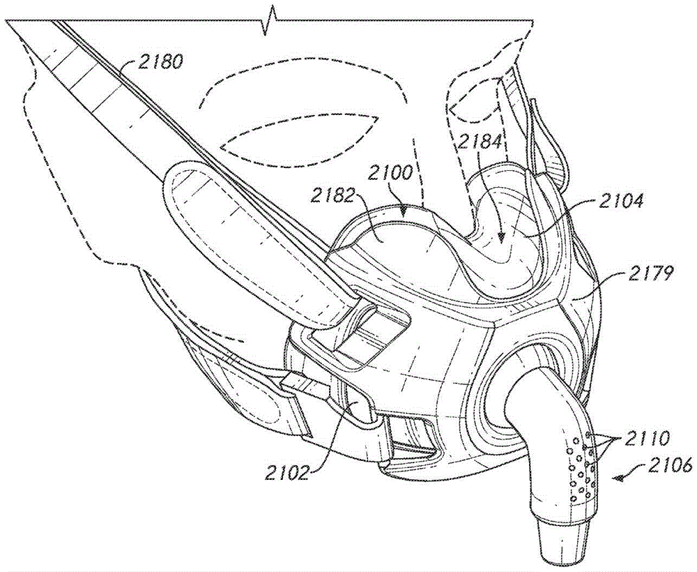
图1至图75展示了在使用者面部上处于适当位置以及与使用者面部分离的面罩组件2100及其部件。所示面罩组件2100是组合式鼻部和口部面罩,在本文可以被称为鼻部-口部面罩。所示面罩组件2100被设计成在使用者的鼻部下方、沿着横向于鼻部延伸的面部部分并且围绕使用者的嘴部进行密封。面罩组件2100有利地不需要与使用者的鼻梁接触。在所示构型中,面罩组件2100不延伸超过使用者的鼻梁。更具体地说,所示面罩组件2100不接触使用者的鼻梁。甚至更具体地说,所示组件2100不接触使用者的鼻梁的向前部分。在一些构型中,组件2100不在竖直地高于沿着使用者眼睛的下缘延伸的总体水平平面的区域中接触面部。面罩组件2100可以或可以不延伸超过使用者的鼻尖。因此,在一些构型中,面罩组件2100覆盖鼻尖。在一些构型中,面罩组件2100的密封件覆盖鼻尖。在一些构型中,所示面罩组件2100优选地不掩盖使用者的鼻尖。在一些构型中或在一些面部几何形状的情况下,使用者的鼻尖延伸超过面罩组件2100的邻接部分。Figures 1-75 illustrate the
如图所示,面罩组件2100优选地被适配成围绕鼻翼或鼻部的翼部延伸并在其上进行密封,鼻翼或鼻部的翼部张开以便围绕鼻孔形成圆形隆起。所示面罩组件2100被适配成围绕限定鼻孔开口的表面进行密封,所述表面可以包括鼻中隔(有时被称为小柱)的肉质外部末端的一部分或整体。在一些构型中,面罩组件2100被适配成向上延伸以便沿着使用者鼻部的左背侧壁和右背侧壁的至少一部分进行密封。在一些构型中,面罩组件2100被适配成沿着左背侧壁和右背侧壁的至少一部分向上延伸但不向上延伸到使用者的鼻梁区域。在一些构型中,面罩组件2100的主密封表面接触使用者鼻部的下侧,可能还接触上唇和/或鼻部的下侧与上唇之间的过渡区域。面罩的辅密封表面可以接触使用者鼻部的侧表面,可能还在鼻部附近的某个位置处接触面颊。这样的主密封表面和辅密封表面可能不会与所有使用者的面部发生接触;然而,这种安排却可以提供与相对较大范围的面部几何形状的合适密封。面罩组件2100优选地还围绕使用者嘴部的至少一部分进行密封。面罩组件2100可以或可以不被适配成在使用者的嘴部与鼻部之间进行密封。As shown, the
如图所示,面罩组件2100包括面罩支撑件,诸如像底座、外壳或面罩壳体2102(参见例如图4)。面罩密封件或缓冲垫2104可以附接至外壳2102,使得外壳2102为面罩密封件2104提供一定量的支撑。然而,在其他构型中,面罩密封件2104可以不包括支撑件并且可以被适配成用于直接组装到相关联接口组件的另一个部件。在一些构型中,外壳2102可以基本上小于所示的外壳。例如,外壳2102可以限定开口,所述开口允许面罩组件2100附接至另一个部件,诸如框架和/或导管连接器(例如,弯管),并且外壳2102可以局限于所述开口而不向面罩组件2100的其他部分提供直接支撑。As shown, the
面罩组件2100可以与框架2178接合或以其他方式由框架支撑,所述框架允许连接至具有任何适合的安排的头部绑带或头戴具2180。面罩组件2100可以被锁到框架2178以便容许仅在正确的取向上进行组装。在一些构型中,头部绑带或头戴具2180可以直接联接至面罩组件2100并且框架2178可以用于其他目的或者省略掉。导管连接器2106也可以附接至外壳2102、框架2178、或者以其他方式相对于面罩组件2100支撑并且被适配成与面罩组件的内部空间连通。共同地,框架2178和头戴具2180可以将面罩组件2100支撑在使用者面部上的适当位置。集体地,面罩组件2100、框架2178以及头戴具2180可以被称为接口组件。面罩组件2100或面罩组件2100结合框架2178可以被称为接口。The
所示导管连接器2106可以以任何适合的方式(包括但不限于本申请内在别处所论述的任何方式)连接至框架2178和/或外壳2102。例如,但非限制地,连接器2106可以连接至外壳2102,使得连接器2106可以相对于外壳2102围绕单个轴线或围绕多个轴线进行转动、枢转或旋转。在一些构型中,连接器2106可以限定与框架2178和/或面罩外壳2102的球接头的一部分,例如但不限于限定另一个部分。所述球接头可以具有任何适合的构型。连接器2106有助于连接至用于向面罩组件2100的内部供应加压呼吸气体的气体导管,诸如供应导管等。可以使用任何适合的连接器2106,在一些情况下,所述连接器可以包括容许连接器2106与气体导管之间的相对旋转的转动或旋转联接。The illustrated
在所示构型中,连接器2106包括含有通气口的弯管,诸如例如但不限于聚碳酸酯弯管。在所示安排中,所述通气口包括偏流孔2110。然而,所述通气口可以包括其他几何形状或安排,例如像位于部件之间的狭槽或受控漏洞。所述通气孔还可以包含扩散材料以减少噪声和/或小股气流。偏流孔2110是被构造成排出空气并且清除CO2以便降低使用者再吸入所呼出二氧化碳的可能性的一群孔眼。虽然偏流孔2110被示出为唯一地位于连接器2106上,但在一些构型中,偏流孔2110可以被设置在外壳2102上、在面罩密封件2104上、或在连接器2106、外壳2102与密封件2104的任意组合上、或者在接口组件或相关联呼吸回路的任何其他部件上。偏流孔2110可以具有任何适合的截面并且可以是圆柱形、砂漏形、在任一方向上呈锥形、完全或部分呈锥形、完全或部分为圆柱形、轮廓被设定成在截面上有变化或诸如此类。In the configuration shown, the
外壳2102总体上为面罩组件2100并且更确切地为面罩密封件2104提供各种各样的支撑结构。外壳2102可以由任何适合的材料形成。在一些构型中,外壳2102由相当刚性的材料形成。在一些构型中,外壳2102由塑料材料形成,诸如聚碳酸酯材料。在一些构型中,面罩组件2100可以包括面罩密封件,所述面罩密封件包括与外壳分离但可附接至外壳的面罩密封件夹具。在这种构型中,面罩密封件夹具将面罩密封件2104连接至外壳2102。在此类构型中,面罩密封件和面罩密封件夹具可以单独形成并且固定在一起,或者面罩密封件和面罩密封件夹具可以集成到单个部件中。在一些构型中,面罩密封件可以包覆模制到面罩密封件夹具上,并且在一些构型中,面罩密封件2104可以直接包覆模制到外壳2102上,所述包覆模制可以包括例如化学和/或机械包覆模制。
在一些构型中,外壳2102包括面罩组件2100的前壁的大部分。这种安排向面罩封密件2104提供有利水平的支撑。例如,外壳2102包括面罩组件2100的前壁的口部部分的大部分。在一些构型中,外壳2102总体上被限制于面罩组件2100的口部部分并且至少在任何明显的程度上不延伸到面罩组件2100的鼻部部分中。这种安排可以向面罩密封件2104提供支撑,同时有利地容许面罩密封件2104的鼻部部分的移动或变形。在其他安排中,如果需要,外壳2102可以延伸到鼻部部分中以便向鼻部部分提供额外的支撑。在所示构型中,外壳2102从中央部分2112朝向相反的侧面部分2116向后张开。中央部分2112包含用于接收连接器2106的孔口2114。外壳2102可以具有遍及中央部分2112和相反的侧面部分2116的总体上或基本上不变的高度。在其他安排中,外壳2102的高度可以改变,诸如通过形成总体上模拟面罩密封件2104的前面形状的形状。外壳2102的高度可以基本上等于面罩密封件2104的口部部分的高度。外壳2102的宽度可以构成面罩组件2100的口部部分的总宽度的显著部分,诸如面罩组件2100的口部部分的总宽度的至少大约四分之三。外壳2102的这种安排可以向面罩密封件2104的中央部分和横向部分提供加强。在一些构型中,外壳2102可以是极小的,诸如像环形支撑圈或框架。In some configurations, the
面罩密封件2104被设计成抵靠使用者的面部进行密封。面罩密封件2104优选地由柔软材料形成,例如像但不限于硅树脂。在一些构型中,面罩密封件2104的至少一部分可以被纹理化以便提高使用者舒适度。例如,在一些构型中,用于形成所示面罩密封件2104的模具的至少多个部分可以被喷砂处理,以便在至少面罩密封件2104将接触使用者皮肤的区域中提供表面纹理。可以使用用于使面罩密封件2104的一个或多个表面纹理化的其他技术。在一些构型中,可能期望的是避免表面纹理化并且为面罩密封件2104的至少面部接触表面提供光滑的表面纹理,这可以增强面罩密封件2104在使用者面部上的抓持并且改进密封特性。The
如上所述,所示面罩密封件2104包括鼻部-口部面罩密封件,并且因此包括至少一个口部开口2122和至少一个鼻部开口2124。在一些构型中,面罩密封件2104可以包括组合式口部-鼻部开口。在一些构型中,面罩密封件2104可以包括多于一个鼻部开口2124。在一些构型中,面罩密封件2104可以包括限定在诸如鼻枕、鼻叉等等上层结构内的鼻部开口2124。在一些构型中,鼻部开口2124可以由鼻部缓冲垫或插入件限定,所述鼻部缓冲垫或插入件可以包覆模制或以其他方式紧固到面罩密封件2104的底座结构。申请人公开号WO2014/062070中披露了这种安排的实例,该公开通过援引以其全文并入本文。As described above, the illustrated
至少一个口部开口2122和至少一个鼻部开口2124优选地与限定在面罩组件2100内的单个腔室2125连通。所示面罩组件2100的腔室2125至少部分地由外壳2102和面罩密封件2104限定。至少一个口部开口2122基本上与接收连接器2106或与所述连接器连通的孔口2114相对。至少一个鼻部开口2124可以竖直地在至少一个口部开口2122上方。至少一个鼻部开口2124可以在面罩组件2100的前后方向上定位在用于连接器2106的孔口2114与至少一个口部开口2122之间。至少一个鼻部开口可以具有轴线,所述轴线相对于竖直线是倾斜的,并且在一些安排中,可以总体上延伸穿过用于连接器2106的孔口2114。The at least one
面罩密封件2104优选地包括一对翼片2126,所述一对翼片在面罩密封件2104的中央部分的上表面2130(例如,参见图7)上方向上延伸。上表面2130可以限定在前后方向上沿着面罩密封件2104的鼻部表面的中央表面延伸的线。这样的线总体上在远离使用者面部的方向上沿着鼻中隔延伸。翼片2126被构造成沿鼻孔旁侧向上延伸、并且在一些构型中在鼻孔上方向上延伸。翼片2126可以接触鼻孔的边缘和/或鼻部的侧面。翼片2126或面罩密封件2104在翼片2126之间的部分可以或可以不覆盖使用者的鼻尖。如本文所述,优选地面罩密封件2104不接触使用者的鼻梁。The
在一些构型中,翼片2126各自包括空气袋,所述空气袋穿过面罩组件2100与从连接器2106到至少一个鼻部开口2124和至少一个口部开口2122的空气路径直接流体连通。翼片2126可以被构造成其体积响应于面罩密封件2104内的升高压力而展开和/或向内挠曲以便适应各种面部和鼻部几何形状并且有助于与使用者的面部形成密封接触。翼片2126的展开可以有助于抵靠使用者面部进行密封,尤其是在使用者的鼻部上和周围沿着变化的轮廓进行密封。翼片2126的向内挠曲允许中央部分(例如,上表面2130)不太受约束地或在面罩密封件2104的材料拉伸较小的情况下向下移动,使得面罩密封件2104可以更好地符合各种鼻部几何形状。类似地,如以下更详细地描述,支撑结构2163的切口区域2202可以有利地允许面罩密封件响应于面罩密封件2104内的升高压力而保持与使用者面部的密封接触。In some configurations, the
翼片2126在上表面2130上方的高度可以被选择以便提供面罩密封件2104在使用者面部上的稳定性(例如,竖直稳定性)与能够适应一定范围的鼻部几何形状或减少由翼片2126造成的视觉干扰之间的期望平衡。总体上,较高的翼片2126倾向于为面罩组件2100提供另外的竖直稳定性,而较低的翼片2126倾向于为更广泛的使用者提供更好的配合并且导致较少的视觉干扰。在一些构型中,翼片高度2126在约10mm与约30mm之间,或者在约15mm与约25mm之间。在一些构型中,翼片高度2126在约15mm与大约22mm之间,或者在约18mm与约20mm之间,包括上述范围内的任何值或子范围。在一些构型中,翼片高度是约18.5mm。The height of the
面罩密封件2104还可以包括用于翼片2126的可以呈悬置构件或弹簧形式的支撑结构或支撑件2163,所述支撑结构或支撑件提供机械刚度和结构以便在面罩密封件2104被使用者佩戴时保持翼片2126的形状。支撑件2163可以包括密封材料的加厚区域。支撑件2163优选地被设定大小、形状和/或以其他方式被构造成将力从翼片2126的后表面或使用者接触表面朝向或向翼片2126的前表面转移。在一些构型中,接口可以包括用于翼片2126的支撑部分或覆盖物,并且支撑件2163可以将力从翼片2126的后表面转移到翼片2126或面罩密封件2104的前表面或者接触或面向支撑部分或覆盖物的其他部分。在一些构型中,支撑件2163可以将力从翼片2126的后表面朝向或向面罩密封件2104或接口的另一支撑部分(例如,外壳2102)转移。支撑件2163可以抵抗或防止翼片2126或者面罩密封件2104的其他相关或邻近部分的塌缩,从而有助于配合到使用者并且诸如响应于所施加的力(例如,头戴具力)而向使用者提供反馈。在一些构型中,支撑件2163可以抵抗或防止翼片2126或者面罩密封件2104的其他相关或邻近部分在不存在显著内部气体压力的情况下塌缩。The
支撑件2163可以有助于维持面罩密封件2104的翼片2126的形状和/或有助于至少响应于正常使用过程中经历的力而维持面罩密封件2104的后壁(其限定面部接触表面)与面罩密封件2104的前壁之间的分离。另外,支撑件2163可以向鼻部区域或鼻部密封部分2168提供支撑。具体地,支撑件2163可以向鼻部区域2168和/或前上部分2150提供结构并且抑制或防止其皱折、起皱或塌缩。如上所述,鼻部区域2168和/或前上部分2150优选地相对较薄,以便允许面罩密封件2104的这些部分贴合使用者的鼻部。相对较薄的鼻部区域2168和/或前上部分2150可以展开并且围绕使用者的鼻部进行密封。支撑件2163邻近或靠近相对较薄的鼻部区域2168和/或前上部分2150提供密封件2104的刚性部分或元件,以便抑制或防止在使用者使他或她的鼻部接合到面罩组件2100中时塌缩。后上部分2156可以有助于防止鼻部区域2168和/或前上部分2150塌缩。The
在一些构型中,支撑件2163有助于降低翼片2126的面部接触部分在使用过程中起皱或皱折的可能性,同时允许横向内部部分如实际限制内所期望的那样薄,诸如以上所描述的那些。支撑件2163可以有助于抑制或防止翼片2126塌缩或者维持翼片2126的所期望的形状。例如,支撑件2163可以有助于维持翼片2126的所期望的前后形状和/或翼片2126的横向或侧向形状。所提供的支撑水平可以在不同方向上改变。在一些构型中,支撑件2163可以被形成为与密封材料分离的部分或与其分离的部件,并且可以是相同材料或不同材料。此类单独支撑件2163可以在需要时联接至翼片2126或面罩密封件2104的其他部分。在鼻下类型的面罩组件(包括鼻罩和组合式鼻部-口部面罩)中,本文披露的支撑件2163可以是特别有用的。然而,支撑件2163还可以用于其他类型的面罩组件或接口,包括例如但不限于覆盖、接触或抵靠使用者的鼻梁进行密封和/或包括T形件或其他类型的前额支撑件的那些。支撑件2163可以用于或被改造以用于接口的可能期望支撑以抵抗塌缩和/或支撑以抵抗过度展开的任何位置。此类位置可以是在密封件的接触使用者鼻部或在使用者鼻部旁侧延伸的部分处或附近,或者可以是在其他位置处。In some configurations, the
在所示安排中,支撑件2163的至少一部分总体上沿着翼片2126在前后方向上延伸。具体地,支撑件2163可以沿着翼片2126的上缘或者沿着翼片2126的上缘连结横向外表面部分和横向内表面部分的区域或凸脊延伸。支撑件2163可以沿着鼻部区域2168的侧面的一部分延伸。支撑件2163可以包括总体上薄的细长形状。从上方观察时,支撑件2163可以包括总体上三角形的形状,其中三角形的底边定位在三角形的顶部或顶点后方。为了实现所期望的支撑水平或出于其他设计考虑(诸如邻近或附近结构的所期望的形状),其他形状是可能的。支撑件2163可以具有另外的部分以便提供其他支撑水平或在其他方向上提供支撑。例如,支撑件2163可以诸如沿着鼻部开口2124的前侧或后侧中的一者或两者彼此连接。在一些构型中,支撑件2163可以完全地延伸穿过翼片2126,例如像延伸到外壳2102。In the arrangement shown, at least a portion of the
如图7至图18B所示,翼片2126(或例如,支撑件2163)可各自包括变薄和/或切口区域2202。切口区域2202可以向后延伸并且定位在翼片2126中的每一者的鼻部区域下方。在一些构型中,切口区域2202向后延伸并且邻近翼片2126中的每一者的鼻部区域定位。然而,在其他构型中,切口区域2202向后延伸并且定位成从翼片2126中的每一者的鼻部区域横向偏移。切口区域2202可以从面罩密封件2104的前上部分2150延伸到面罩密封件2104的后上部分2151,使得切口区域2202缠绕在翼片2126中的每一者的横向侧部分2210周围。因此,在一些构型中,切口区域2202通常是弯曲的、笔直的和/或具有可变曲率。在一些构型中,切口区域2202可以从前上部分2150倾斜到后上部分2151和/或从后上部分2151倾斜到前上部分2150。在一些其他构型中,切口区域2202基本上是平坦的或者具有最小的倾斜。As shown in FIGS. 7-18B , the tabs 2126 (or, for example, the supports 2163 ) may each include thinned and/or
如示出的构型所示,切口区域2202延伸跨过前上部分2150的至少一部分和后部部分2151的至少一部分。例如,切口区域2202可以围绕面罩密封件2104的横向侧部分2110并且跨过后部部分2151朝向口部开口2122上方的后上部分的大致中心延伸。在一些构型中,切口区域2202延伸跨过后上部分和/或前上部分的大约1/16、1/8、1/4和/或1/2或更多。在一些构型中,切口区域2202跨过后上部分2151延伸一段距离,所述距离未达到鼻部区域2200的鼻部开口2124的横向侧的位置。As shown in the configuration shown, the
在所示构型中,切口区域2202定位在翼片2126的鼻部区域下方。然而,在其他构型中,切口区域2202可以定位在翼片2126的鼻部区域上方和/或定位在与鼻部区域相同的平面中。例如,切口区域2202可以定位在翼片2126的鼻部区域下方大约0.1mm至0.5mm、0.5mm至1mm、1mm至10mm、10mm至50mm、50mm至1cm、1cm至2cm和/或2cm至3cm或更多。在一些构型中,切口区域2202几乎邻近口部开口2122的上侧定位。在其他构型中,切口区域2202定位在鼻部开口2124的上方、下方和/或与其成平面。然而,在一些构型中,切口区域2202沿着翼片2126的横向侧延伸。在此类构型中,切口区域2202可以不延伸跨过前上部分2150的一部分和/或后上部分2151的一部分延伸,并且可以限制到翼片2126或终止于鼻部区域2200内。In the configuration shown, the
面罩组件2100的所示面罩密封件2104包括厚度范围和厚度构型,如图7至图18B所示。所述厚度是不同的以便利用所示面罩密封件2104的不同区域中的不同特性或在不同区域中提供不同特性。例如,不同区域中的厚度可以进行选择以便实现所述区域和/或整个面罩密封件2104的期望特性。此类特性可以包括例如:允许面罩密封件2104符合使用者的面部几何形状以便增强密封性质或舒适度;在不具有大量内部气体压力的情况下支撑面罩密封件的形状以便促进配合,和/或响应于内部气体压力和/或外部压力(例如,由头戴具力引起的)而支撑面罩密封件的形状;或者提供强度或耐久性。The illustrated
如上所述,面罩密封件2104可以包括不同厚度的各种区域。本申请人的公开号WO2015/193821 A1中披露了这种安排的实例,该公开通过援引以其全文并入本文。总体上,面罩密封件2104的外表面限定在方向上没有突然变化的相对平滑的成形或弯曲表面。不同厚度是由在面罩密封件2104的内表面上明显的壁厚变化产生或者由所述面罩密封件的内表面的形状变化产生。As mentioned above, the
支撑件2163可以具有与翼片2126的其他部分不同的厚度,并且可以具有比翼片2126的其他部分大的厚度。在一些构型中,支撑件2163可以具有面罩密封件2104的最大厚度或在最大厚度之中。在一些构型中,支撑件2163的一部分或整体可以具有在约1.5mm与约3.5mm之间的厚度。在所示构型中,支撑件2163的一部分或整体可以具有约2.5mm的厚度。支撑件2163的厚度可以是恒定的或可变的。The
在一些构型中,用于翼片的支撑结构2163比鼻部区域2168和前上部分2150厚。在一些构型中,在鼻部区域2168和前上部分2150与翼片2126之间存在相对突然的厚度过渡。相比之下,在外周边部分2162、翼片2126与后上部分2151之间的厚度过渡是更渐进的。此外,在至少一些构型中,外周边部分2162、后上部分2151与口部开口2122之间的厚度过渡是相对渐进的。以下进一步描述面罩密封件2104的不同部分。In some configurations, the
为了降低面罩密封件2104的面部接触区域中的至少一些在使用过程中皱折的发生率,已经发现,面罩密封件2104的外周边部分2162(其总体上邻近面罩密封件2104的面部接触部分中的一些或全部)在外周边部分2162相当刚性或相较于面罩密封件2104的邻近部分或其他部分相对刚性时提供令人期望的性能。在所示安排中,外周边部分2162沿着面罩密封件2104的后部上的总体竖直延伸的部分延伸并且在面罩密封件2104的后部的底部处稍微向内卷起。另外,外周边部分2162从面罩密封件2104的后向侧向所述面罩密封件的横向侧的至少一部分卷起。In order to reduce the incidence of wrinkling during use of at least some of the face-contacting areas of the
在所示安排中,外周边部分2162位于口部开口2122的每个横向侧上。在一些构型中,外周边部分2162沿着口部开口2122的整个高度延伸。外周边部分2162的上端可以至少延伸到口部开口2122的上端附近。外周边部分2162的下端可以在口部开口2122的下端下方延伸。如上所述,在一些构型中,外周边部分2162在口部开口2122下方向内卷起,使得外周边部分2162的部分竖直定位在口部开口2122的部分的下方。In the arrangement shown, an outer
外周边部分2162的相对增大的厚度可以有助于抵抗或防止面罩密封件2104在不存在大量内部气体压力的情况下塌缩,从而有助于配合到使用者并且诸如响应于所施加的力(例如,头戴具力)而向使用者提供反馈。外周边部分2162可以帮助维持面罩密封件2104的横向侧的弯曲形状和/或帮助至少响应于正常使用过程中经历的力而维持面罩密封件2104的后壁(其限定面部接触内表面)与面罩密封件2104的前壁之间的分离。在一些构型中,外周边部分2162的一部分或整体的厚度可以是在约1.0mm与约2.0mm之间。在所示构型中,外周部分2162的一部分或整体优选地具有约1.5mm的厚度。外周边部分2162的厚度在外周边部分2162的边界内可以是恒定的或变化的。The relatively increased thickness of the outer
在一些构型中,与周围的密封表面(例如,支撑结构2163)相比,切口区域2202具有减小的壁厚度。例如,在至少一些实施例中,切口区域2202中的一些或全部可以具有与周围密封表面相比减小的壁厚度,所述周围密封表面的全部或一部分可以由支撑结构2163的全部或一部分限定。在一些构型中,周围密封表面包括大约3mm的壁厚度。如上所述,包括外周边部分2162的周围密封表面中的一些或全部可以具有在约1.0mm与约2.0mm之间的厚度。然而,例如,支撑结构2163的切口区域2202可以具有在约0.1mm至0.2mm之间、0.2mm至0.3mm之间、0.3mm至0.4mm之间、0.4mm至0.5mm之间、0.5mm至0.6mm之间、0.6mm至0.7mm之间、0.7mm至0.8mm之间、0.8mm至0.9mm之间和/或0.9mm至1.0mm之间或更大的壁厚度。在所示构型中,切口区域2202的一部分或全部优选地具有约.3mm的壁厚度。切口区域2202的厚度在切口区域2202的边界内可以是恒定的或变化的。In some configurations, the
与周围密封表面相比,切口区域2202的减小的壁厚度可以合意地提供比周围密封表面更可变形和/或可压缩的区域。例如,切口区域可以不如周围密封表面刚性和/或比周围密封表面更可展开。这在例如向翼片2126施加横向力(诸如由较宽的鼻部施加)时可能是期望的。因此,与没有切口区域2202和/或有或没有支撑结构2163的翼片2126相比,切口区域2202可以能够更容易地压缩,以便更好地适应施加到翼片2126的鼻部区域的横向力。代替保持刚性,切口区域2202将允许翼片2126压缩,同时保持面罩密封组件的结构完整性(参见例如图10A至图10C、图11A至图11B)。这种构型对于佩戴面罩密封组件的患者可能更舒适。The reduced wall thickness of the
在一些构型中,面罩密封件2104的支撑结构2163的切口区域2202包括凹轮廓2204。例如,图8展示了切口区域2202在切口区域2202的后部部分2160处包括凹轮廓2204。在所示构型中,凹轮廓2204的相对低点定位在每个切口区域2202的后部部分2160的大致中心处。然而,在其他构型中,凹轮廓更靠近一侧定位。在其他构型中,切口区域2202的凹轮廓2204被定位成更靠近翼片2126的鼻部区域。In some configurations, the
在一些构型中,切口区域2202沿着切口区域2202的一部分或整个长度包括凹轮廓2204。在所示构型中,凹轮廓2204的相对低点定位在每个切口区域2202的宽度的大致中心处。然而,在其他构型中,凹轮廓更靠近一侧定位。在其他构型中,切口区域2202的凹轮廓2204被定位成更靠近翼片2126的鼻部区域。如图8所示,凹轮廓2204沿着切口区域2202的后部部分2160平滑地向内过渡。在一些构型中,凹轮廓2204向内朝向面罩密封件2104的前上部分2150延伸相对短的距离。在一些构型中,凹轮廓2204向内朝向面罩密封件2104的前上部分2150延伸更大量的距离。在一些构型中,凹轮廓2204沿着切口区域2202的后部部分2160向下延伸。In some configurations, the
通常,翼片2126的展开可以有助于抵靠使用者面部进行密封,尤其是在使用者的鼻部上和周围沿着变化的表面轮廓2206进行密封。例如,如图8所示,鼻部区域2168包括表面轮廓2206。表面轮廓2206可以沿着鼻部区域2168的内侧延伸。表面轮廓2206可以从面罩密封件2104的后上部分大体向内朝向面罩密封件2104的前上部分2150的中心延伸。表面轮廓2206可以合意地增加患者的舒适度并且有助于确保与使用者的面部形成密封,同时在需要适应特定使用者时允许鼻部区域2168向外移动。In general, the deployment of the
图9A至图9D示出了支撑结构2163的切口区域2202的凹轮廓2204的近距离视图。如示出的构型中所示,凹轮廓2204可以竖直地向下延伸(相对于图9A至图9D中所示的取向)并且向内朝向面罩密封件2104的内部延伸。因此,当向翼片2126施加足够的力时,凹轮廓2204可以允许切口区域2202向内朝向面罩密封件2104的内部折叠。9A-9D show close-up views of the
通常,凹轮廓2204、表面轮廓2206和/或切口区域2202的壁的减小的厚度度可以有助于减少材料。这可以合意地减小体积并且增加患者的舒适度。在一些构型中,凹轮廓2204可以促使切口区域2202的壁向内朝向面罩密封组件的内部腔室2125折叠。在面罩密封件2104抵靠患者的面部折叠时,这可以有利地减小体积。类似地,当使用者佩戴面罩密封件2104时,切口区域2202的凹轮廓2204可以通过与使用者的面部形成更好的密封来帮助最小化泄漏。例如,代替在面罩密封件2104横向展开时向外展开和或向外凸出,切口部分2202可以有利地向内折叠以便保持与使用者面部接合并且防止面罩密封件2104移动到不期望的位置。In general, the reduced thickness of the
在一些构型中,当向翼片2126施加力时,凹轮廓2204允许切口区域2202更好地压缩。如上所述,当向翼片2126施加横向力时,凹轮廓2204可以允许切口区域2202横向地和/或竖直地且向内地折叠。In some configurations, the
例如,图10A至图10C和11A至图11B展示了面罩组件的顶视图,示出了面罩密封件2104的切口区域2202。在这个实例中,向翼片2126的鼻部区域2402施加恒定的横向力2400。在一些构型中,横向力2400由比鼻部区域2402的中性宽度更宽的使用者鼻部产生(例如,当不向鼻部区域2402施加横向力或施加最小的横向力时)。然而,在未示出的其他构型中,可以在任何方向上施加力和/或力可以改变。如示出的实例中所示,当向翼片2126施加力2400时,切口区域2202可以压缩。图10A展示了当不施加力或施加很小的力时的示例性构型。如图所示,支撑结构2163包括内部区域2404和外部区域2406,它们配合以限定切口区域2202。在此类构型中,切口区域2202将内部区域2404与外部区域2406分开。当不向翼片2126施加力或施加很小的力时,内部区域2404和外部区域2406的外端以间隙2408间隔开。图10B展示了当向翼片2126的鼻部区域施加横向力2400时的面罩密封件2104的构型。如示出的构型中所示,内部区域2404朝向切口区域2202的外部区域2406压缩。在所示构型中,当向翼片2126的鼻部区域施加横向力2400时,外部区域2406保持相对固定。如图10B所示,在切口区域2202的内部区域2404被压缩时,间隙2408的大小减小。在翼片2126被压缩时,内部区域2404朝向外部区域2406移动。在一些构型中,取决于向鼻部区域施加的力的量,切口区域2202的内部区域2404不与外部区域2406接触和/或重叠。然而,如图10C所示,内部区域2404可以与外部区域2406接触和/或至少部分地重叠。For example, FIGS. 10A-10C and 11A-11B illustrate top views of the mask assembly showing the
在一些构型中,面罩密封件2104在鼻部密封表面中提供柔性,以便适应使用者的各种鼻部几何形状和不同大小的鼻部区域,特别是各种鼻部宽度。在一些此类构型中,本文所述的密封件2104通过在使用者鼻部的外侧上向内夹紧来改善与使用者的下鼻部表面的密封。In some configurations, the
如图12至图15所示,与其他面罩密封件相比,所述面罩密封件可以包括减小的鼻部区域宽度2410。减小的鼻部区域宽度2410可以合意地提供增加与使用者鼻部的侧面可靠接合的感觉。例如,鼻部区域宽度2410可以是面罩密封件2104的上部部分的宽度的大约二分之一。在一些构型中,鼻部区域宽度2410是面罩密封件2104的上部部分的宽度的约1/4。在一些构型中,鼻部区域宽度2410可以从面罩密封件2104的中心向外朝向面罩密封件2104的外周边部分2162延伸小于口部开口2122的横向宽度的距离。在一些构型中,鼻部区域宽度2410从面罩密封件2104的中心向外朝向面罩密封件2104的外周边部分2162延伸与口部开口2122的横向宽度大约相同和/或更大的距离。在一些构型中,鼻部区域宽度2410从面罩密封件2104的中心向外延伸到切口区域2202。As shown in Figures 12-15, the mask seal may include a reduced
在一些构型中,总鼻部区域宽度2412是大约20mm至25mm宽、25mm至30mm宽、30mm至35mm宽、35mm至40mm宽、40mm至45mm宽、45mm至50mm宽和/或50mm或更宽。优选地,总鼻部区域宽度2412是大约40mm宽。In some configurations, the total
在一些构型中,减小的总鼻部区域宽度2412导致在佩戴时增加与使用者鼻部的侧面的接合。因此,如上所述,面罩密封件2104可以为使用者的面部提供更好的密封。此类构型可以允许使用者感觉到面罩密封件2104正确地定位和/或与使用者的鼻部适当地密封。在一些构型中,面罩密封件2104的翼片2126可以通过增加向使用者鼻部施加的密封力而向内夹紧在使用者的鼻部上。In some configurations, the reduced overall
在一些构型中,面罩组件包括前部部分2420。前部部分2420可以包括凹入前表面2430以及一个或多个扇形横向侧2440。例如,图16展示了面罩组件2100的实例,所述面罩组件包括由外壳或面罩壳体2102形成的凹入前表面2430。凹入表面2430可以定位在面罩密封件2104的前部上,并且可以被构造成接收框架2178。凹入前表面2430可以沿着外壳或面罩壳体2102的周边的一部分或全部形成,其中它接合到密封件2104。在所示实例中,凹入前表面2430在前部部分2420的表面中形成台阶。凹入前表面2430通常沿着外壳2102的周边的侧面和下边缘延伸。在一些构型中,台阶的深度沿着其长度渐缩,使得沿着外壳2102的周边的上边缘没有台阶或有很小的台阶,并且密封件2104沿着外壳2102的周边的上边缘与外壳2102齐平。In some configurations, the mask assembly includes a
台阶的深度可以取决于密封件2104的大小。例如,密封件2104可以提供一系列大小,以便适应具有一系列面部大小和面部几何形状的使用者。在一些构型中,密封件2104接合至单一大小的外壳2102。在一些构型中,密封件2104相对于外壳2102的大小差异决定了台阶的深度。在一些构型中,凹入前表面2430以恒定深度或变化深度凹入。例如,凹入前表面2430的深度可以在凹入前表面2430的整个表面上是恒定的。然而,在一些构型中,上凹入表面2432(下文更详细地描述)凹入的深度小于和/或大于凹入前表面2430的其余区域的深度。The depth of the steps may depend on the size of the
在一些构型中,前部部分2420包括形成在密封件2104内的上凹入表面2432。上凹入表面2432可以定位在前上部分2150处。在所示构型中,上凹入表面2432沿着翼片2126的前侧定位。上凹入表面2432可以沿着面罩密封件2104的前侧2422的外周部分2162延伸。上凹入表面2432可以围绕面罩密封件2104的侧面向后延伸。在一些构型中,上凹入表面2432基本上围绕面罩密封件2104的外周边部分2162缠绕。在一些构型中,上凹入表面2432仅定位在外周边部分2162的一部分上。例如,上凹入表面2432可以在密封件2104的每侧上向下延伸前侧2422的高度的大约一半。在一些构型中,上凹入表面2432向下延伸小于前侧2422的一半,并且在一些情况下,向下延伸前侧2422的大约1/3。In some configurations, the
在一些构型中,上凹入表面2432在前上部分2420的上周边之间形成沿着翼片2126的周边或上边缘的曲率延伸的台阶式过渡。在一些构型中,台阶式过渡以恒定深度或变化深度延伸。例如,台阶式过渡的深度在前上部分2420的上周边与凹入前表面2430之间的整个台阶式过渡中可以是恒定的。然而,在一些构型中,台阶式过渡变化。例如,台阶式过渡可以是渐缩的。在这种安排中,深度可以在台阶式过渡的下部或横向末端处最小。然而,在一些实施例中,深度在台阶式过渡的上部末端处最小。In some configurations, the upper
台阶式过渡的深度可以取决于许多因素,包括面罩密封件的大小。例如,台阶式过渡的渐缩的深度对于更大尺寸的面罩密封件可以更大或者对于更小尺寸的面罩密封件可以更小。在一些构型中,前上部分2420包括多个上部拐角。例如,前上部分2420可以包括第一上部拐角和/或第二上部拐角。多个上部拐角可以形成在翼片2126的前部部分上。多个上部拐角可以限定沿着前上部分2420的周边延伸的上凹入表面2432的周边的全部或一部分。The depth of the stepped transition can depend on many factors, including the size of the mask seal. For example, the tapered depth of the stepped transition may be greater for larger size mask seals or smaller for smaller size mask seals. In some configurations, the
在一些构型中,与通常位于上部拐角(例如,第一上部拐角与第二上部拐角)之间的上部中心部分相比,台阶式过渡的深度和/或台阶式过渡的渐缩在多个拐角处更大。In some configurations, the depth of the stepped transition and/or the taper of the stepped transition may be more than The corners are bigger.
在一些构型中,凹入前表面2430和/或上凹入表面允许框架2178插入到面罩密封件2104中。例如,上凹入表面2432可以接收框架2178的全部或一部分。因此,在一些构型中,上凹入表面2432的台阶式过渡具有大于或等于框架的厚度的最大深度。类似地,凹入前表面2430可以接收框架2178的全部或一部分。这些构型可以有利地提供稍微齐平的表面光洁度,这对使用者来说更美观。在一些构型中,可以减小面罩密封件2104的视觉大小和/或可以减少面罩密封件中使用的材料的量。因此,在一些构型中,面罩密封件2104对于使用者而言体积较小和/或不太突兀(例如,参见图17)。In some configurations, the concave
在一些构型中,上凹入表面2432可以仅按某些密封件缓冲垫大小来提供。例如,上凹入表面2432可以仅设置在某些中型或大型面罩密封件2104上。在一些构型中,上凹入表面2432设置在某些小型或中型面罩密封件2104中。在一些构型中,上凹入表面2432可以存在于所有尺寸的面罩密封件2104中。上凹入表面2432的深度可以根据面罩密封件2104的大小而变化。在一些构型中,上凹入部分的深度可以与用于小型和/或中型面罩密封件2104的框架2178的厚度基本上相同,并且深度可以大于用于大型面罩密封件2104(例如,尺寸大于小型和/或中型面罩密封件2104)的框架2178的厚度。在此类构型中,这可能导致面罩密封件2104悬挂在框架2178上和/或延伸超过所述框架。在一些构型中,上凹入表面2432被构造成允许单一大小的框架与多个不同大小的面罩密封件2104一起使用,而框架2178对于多个面罩密封件2104来说不会太大或太小。In some configurations, the upper
在一些构型中,上凹入表面2432为鼻部密封表面提供更好的支撑。例如,图17示出了插入和/或在上凹入表面2432内定位的框架2178和框架翼片2179。如示出的构型中所示,框架翼片2179可以定位在上凹入表面2432内。在这种构型中,框架翼片2179的外表面与上凹入表面2432齐平。这种安排可以通过为面罩密封件2104的前侧2422和翼片2126提供额外刚性来为鼻部密封表面提供额外支撑。在一些构型中,框架翼片2179合意地为密封翼片2126提供支撑。在此类构型中,框架翼片2179可以帮助防止密封翼片2126在使用中远离使用者的鼻部偏转。在一些构型中,这种安排可以有助于在面罩密封件2104变得过度变形的情况下防止框架翼片2179接触或挖入使用者的面部中。因此,在一些构型中,凹入前表面2430可以有利地允许面罩密封件2104随时间推移而维持其结构并且可以增加面罩密封件2104的耐久性。在一些构型中,凹入前表面2430允许单一大小的框架2178与具有不同尺寸的面罩密封件2104一起实施的用途。因此,在一些构型中,凹入前表面2430降低了面罩组件的制造成本。In some configurations, the upper
图18A和图18B展示了包括扇形横向侧2440的面罩密封件2104的实例。扇形横向侧2440可以有利地减少面罩密封件2104的材料量,并且可以提供更美观或视觉上更小的面罩密封件2104。如示出的构型中所示,面罩密封件2104的外壁沿着面罩密封件2104的外周边部分2162平滑地过渡。然而,在其他构型中,外周边部分2162可以包括至少三个不同的区段(例如,上部部分、中心部分和下部部分),并且外周边部分2162可以不在每个区段之间平滑地过渡。18A and 18B illustrate an example of a
在所示构型中,扇形横向侧2440沿着面罩密封件2104的侧面形成凹面部分。扇形横向侧2440可以沿着面罩密封件2104的外周边部分2162定位在翼片2126下方。在一些构型中,扇形横向侧2440定位成至少部分地与翼片2126的底部重叠。在一些构型中,扇形横向侧2440完全定位在翼片2126下方。在一些构型中,扇形横向侧2440的凹面部分的中心2442大致与口部开口2122的顶部对齐。在一些构型中,凹面部分的中心2442定位在口部开口2122上方,但在鼻部区域2168下方。在一些构型中,凹面部分的中心2442定位在鼻部区域2168上方。In the configuration shown, the scalloped
在一些构型中,扇形横向侧2440沿着面罩密封件2104的外周边部分2162的大约一半延伸。在一些构型中,扇形横向侧2440沿着面罩密封件2104的外周边部分2162的大约1/8、1/4、1/3、3/4或更多延伸。In some configurations, the scalloped
如示出的构型中所示,扇形横向侧2440可以为鼻部区域2168提供额外的竖直支撑。例如,当向鼻部区域施加横向力时和/或当面罩密封件2104内的压力增加时,扇形横向侧2440可以提供额外的支撑。例如,扇形横向侧2440在面罩密封件2104的其他部分中可以有利地有助于将载荷从面颊传递到面罩密封件2104的侧面上的框架2178,这有助于保持与使用者面部的接合。因此,扇形横向侧2440可以在使用者的鼻部与面罩密封件2104之间提供改进的密封。As shown in the configuration shown, the scalloped
图19A和图19B展示了面罩组件2100的实例,所述面罩组件包括由外壳或面罩壳体2102形成的凹入前表面2430。凹入前表面2430可以定位在面罩密封件2104的前部上,并且可以接收框架2178的各种构型。例如,如图19A和图19B所示,框架2178和框架翼片2179定位成插入和/或在上凹入表面2432内,所述上凹入表面可以全部或部分地由密封件2104限定。19A and 19B illustrate an example of a
在一些构型中,外壳2102可以包括偏置通气口2502。偏置通气口2502可以包括被构造成排出空气并且清除CO2以便降低使用者再吸入所呼出二氧化碳的可能性的多个孔。虽然仅在外壳2102上示出偏置通气口2502的孔,但是在一些构型中,偏置通气口2502可以设置在面罩密封件2104、弯管2520或其他导管连接器上,或者设置在外壳2102、面罩密封件2104、弯管2520的任何组合上,或者设置在接口组件或相关联的呼吸回路的任何其他部件上。孔可以具有任何适合的截面并且可以是圆柱形、砂漏形、在任一方向上呈锥形、完全或部分呈锥形、完全或部分为圆柱形、轮廓被设定成在截面上有变化或诸如此类。孔的截面可以增加或减少通过孔排出的空气。In some configurations, the
在一些构型中,框架2178可以附接和/或以其他方式包括弯管2520。虽然图19A和图19B示出了具有附接至框架2178的弯管2520的面罩组件2100的实例,但是在一些构型中,弯管直接附接至面罩外壳2102和/或面罩密封件2104以及其他面罩部件。弯管可以是可移除的和/或永久地附接至框架2178和/或外壳2102。弯管2520可以形成非水平连接器。例如,弯管2520可以包括弯曲部。在一些构型中,弯管2520以大约10度至20度、20度至30度、30度至40度、40度至50度、50度至60度、60度至70度、70度至80度和/或80度至90度以及其他范围的角度弯曲。这种构型可以合意地减小面罩组件的体积、减少材料和/或在期望方向上重新引导气流。在一些构型中,弯管2520是水平的、竖直的或笔直的。In some configurations,
弯管2520可以包括上部部分和下部部分。上部部分和下部部分可以通过弯曲部分离,如上文论述。弯管2520可以包括各种连接特征,诸如框架连接狭槽2532、保持凹口2534以及入口连接器2530等等。入口连接器2530可以形成弯管2520的上部部分,使得入口连接器2530可以与面罩外壳2102的入口2510连接。入口连接器2530可以通过卡扣配合、压配合、过盈配合和/或其他配合构型来将弯管2520可移除地连接至入口2510。因此,在一些构型中,弯管2520可以在一端(例如,下部部分)处连接至气体供应导管(未示出),并且定位在弯管2520的另一端(例如,上部部分)处的入口连接器2530提供流动路径,通过所述流动路径,加压气体流通过面罩密封件2104的内部腔室2125而提供至使用者。
框架连接狭槽2532可以由弯管2520中的狭槽或切口形成。在一些构型中,框架连接狭槽2532可以由多个突起形成,诸如从弯管2520的相邻表面部分向外延伸的肋。例如,如图26和图28所示,弯管2520包括从弯管2520向外延伸以便接收和/或保持框架2178的弯管连接器2516的两个肋。如图21A和图21B所示,框架连接狭槽2532可以定位成从弯管2520的上部部分的端部偏移。在一些构型中,框架连接狭槽2532在弯曲部的一侧上定位在弯管2520的下部部分上。框架连接狭槽2532可以完全缠绕在弯管2520周围。在一些构型中,如图所示,框架连接狭槽2532仅围绕弯管2520的一部分延伸。
在一些构型中,弯管2520可以包括防窒息(A-A)阀2522。A-A阀2522可以提供流动路径,环境空气可以通过所述流动路径进入面罩2100。例如,在某些情况下,如果流发生器未能向面罩提供气体供应,那么阀2522使得使用者能够使用环境空气。In some configurations,
A-A阀2522可以包括阀瓣2524、阀座或保持器2526和阀口2536以及其他部件。阀口2536可以包括一个或多个开口,以便提供空气从大气流到面罩密封件2104的内部腔室2125的路径。阀口2536可以定位在弯管2520的一端处。例如,阀口2536可以定位在弯管2520的下部部分的后侧2540上,使得阀口2536形成大致面向面罩密封件2104或者面罩密封件2104的前凹表面2508的开口(如下所述)。在一些构型中,阀口2536定位在弯管2520的入口连接器2530的下方。在一些构型中,阀口2536大致平行于面罩密封件2104的前凹表面2508。在一些构型中,阀口2536朝向面罩密封件2104的前凹表面2508向下成角度。The
阀瓣2524可以定位成配合在弯管2520内和/或在阀座2526的至少一部分内。阀瓣2524可以打开和关闭阀口2536以便允许空气流过阀口2536。例如,当流发生器通过面罩密封件2104向使用者提供气流时,阀瓣2524相对于阀座2526打开,从而关闭阀口2536。当流量发生器不向面罩密封件2104提供气流时,阀瓣2524相对于阀座2526关闭,并且阀口2536打开以便允许使用者通过阀口2536吸入环境空气。阀座2526可以将阀瓣2524支撑在可操作位置。在一些构型中,阀座2526限定止动件,所述止动件防止阀瓣2524反转或向下延伸出弯管2520。如以下更详细地描述,在一些构型中包括阀2522的弯管2520可以定位在面罩密封件2104的凹前表面的前方。The
图20展示了可以在面罩组件2100中实施并且可以连接至本文所述的外壳2102的实施例的示例性框架2178。框架2178可以通过各种安排附接至外壳2102。例如,框架2178可以滑动到面罩密封件2104中,和/或通过卡扣配合或压配合以及其他合适的附接安排附接至面罩密封件2104。如上所述,框架2178可以装配到面罩密封件2104的前凹入表面2430中,包括上凹入表面2432。在一些构型中,框架2178被构造成可从面罩密封件2104重复地移除,以便允许面罩密封件2104和框架2178中的一者或两者可互换。然而,在一些构型中,框架2178可以永久地附接至面罩密封件2104。20 illustrates an
在一些构型中,框架2178可以包括至少一个头戴具连接器2512、通气孔口2514和/或弯管连接器2516以及其他特征或部件。至少一个头戴具连接器2512可以连接至头戴具和/或接收头戴具。在一些构型中,头戴具连接器2512可以形成在框架2178中。例如,框架2178可以包括一个、两个、三个、四个、五个和/或六个或更多个头戴具连接器2512。如图20所示,所示的框架2178包括一对相对的头戴具连接器2512,它们形成用于各自接收头戴具的至少一部分(诸如头戴具的连接器夹具)的狭槽。In some configurations, the
至少一个头戴具连接器2512可以沿着框架2178的前侧定位。例如,至少一个头戴具连接器2512可以从框架2178的前侧向外(例如,向前和/或横向向外)延伸,并且至少部分地限定框架2178中的用于连接头戴具的孔口的边界。如图20所示,头戴具连接器2512可以在高度和/或宽度方向上仅沿着框架2178的前侧的一部分延伸。头戴具连接器2512可以竖直地延伸,或者可以在框架2178的顶侧与框架2178的下侧之间成角度。在所示安排中,头戴具连接器2512的上端相对于头戴具连接器2512的下端向前和/或向内定位。头戴具连接器2512可以至少部分地定位在每个翼片2126和/或框架2178的鼻部区域下方。在一些构型中,头戴具连接器2512可以定位在外壳2102或面罩组件2100的其他部件上。At least one
如图20所示,框架2178可以包括通气孔口2514,所述通气孔口的形状被确定为容纳或接收偏置通气口2502。因此,在一些构型中,通气孔口2514与偏置通气口2502对准。如上所述,一些安排可以有利地允许排出的空气穿过框架2178到达大气。例如,偏置通气口2502可以优选地设置在外壳2102中并且与框架2178和/或头戴具中的任何开口连通或对准。在一些构型中,偏置通气口2502位于外壳2102的未被框架2178覆盖的至少一部分内,或者位于在框架2178与外壳2102之间限定的空间内。在一些构型中,偏置通气口2502至少部分地被框架2178覆盖。如果排出的空气接触框架2178,那么此类安排可能会影响流率。As shown in FIG. 20 , the
在一些构型中,当框架2178连接至面罩密封件2104时,偏置通气口2502可以至少部分地延伸穿过框架2178的通气孔口2514(参见例如图19A和图19B)。在一些构型中,当偏置通气口2502定位在通气孔口2514内时,偏置通气口2502定位成与框架2178齐平。In some configurations, the offset
在一些构型中,框架2178可以包括弯管连接器2516。弯管连接器2516可以接收和/或连接至弯管2520,如图22A至图23B所示。弯管连接器2516可以由位于框架2178的下边缘上的切口限定或者包括所述切口,所述切口可以被构造成接收弯管2520的至少一部分。例如,弯管连接器2516的切口可以连接至弯管2520,使得框架2178装配到弯管2520的框架连接狭槽2532中。In some configurations,
在一些构型中,弯管连接器2516可以通过卡扣配合、压配合、过盈配合和/或其他配合构型连接至弯管2520。例如,弯管连接器2516可以优选地包括一对保持凸起2518。保持凸起2518可以在弯管连接器2516的下部拐角上彼此相对地定位。保持凸起2518可以与弯管2520的相应连接特征接合,诸如保持凹口2534。保持凹口2534可以定位在弯管2520的框架连接狭槽2532的下端处。在一些构型中,框架2178可以通过诸如焊接、包覆模制和/或粘合剂等连接手段永久地连接至弯管2520。In some configurations,
如上所述,弯管2520可以连接至框架2178。在一些构型中,如图22A至图23B所示,在框架2178连接至面罩密封件2104之前,弯管2520可以连接至框架2178。例如,弯管可以滑入弯管连接器2516的切口中,使得弯管连接器2516与框架连接狭槽2532对齐。当弯管连接器2516滑入框架连接狭槽2532中时,保持凸起2518可以与相应的保持凹口2534对齐。因此,弯管2520可以由框架2178保持以便形成子组件,所述子组件随后联接至面罩密封件2104。
在一些构型中,如图21A和图21B所示,例如,弯管2520经由弯管2520的入口连接器2530直接连接至外壳2102的入口2510。在一些构型中,弯管2520可以在框架2178连接至弯管2520之前或之后连接至外壳2102。然而,在其他构型中,弯管2520必须首先连接至框架2178,并且随后弯管2520/框架2178子组件可以连接至外壳2102。在一些构型中,弯管2520可以在外壳2102与框架2178之间提供连接。例如,在此类构型中,框架2178在没有由弯管2520提供的连接的情况下可以不连接至外壳2102。在一些构型中,弯管在从平面2506向下成角度的方向上与外壳2102连接和/或断开,所述平面大致垂直于面罩密封件2104的密封表面2504。例如,平面2506可以基本上垂直于弯管2520连接至框架2178的方向。在一些构型中,平面2506可以基本上垂直于框架2178连接至弯管2520的方向。弯管2520可以通过多个连接安排(诸如卡扣配合安排)可移除地附接至外壳2102。In some configurations, as shown in FIGS. 21A and 21B , for example,
当弯管2520连接至外壳2102时,弯管2520可以是不可旋转的。例如,当框架2178、弯管2520和外壳2102组装时,框架2178也许不能相对于外壳2102旋转。在一些构型中,外壳2102与弯管2520之间的连接安排有利地允许由CPAP软管产生的软管拖曳力与面罩隔离。在此类构型中,柔性导管(未示出)可以形成将CPAP软管连接至弯管2520的中间部件。在一些构型中,外壳2102与弯管2520之间的连接安排合意地成角度,以便提供对于使用者佩戴来说不太突兀的低轮廓面罩组件2100。因此,与传统面罩组件相比,弯管2520在佩戴时可以不从使用者的面部延伸那么远。此类构型可以减小由弯管2520产生的力矩臂和面罩组件2100上的潜在软管拖曳力。When the
在一些构型中,外壳2102包括前凹表面2508,所述前凹表面至少部分地围绕入口2510(例如,参见图21B和图24)。例如,前凹表面2508可以相对于入口2510偏移,使得前凹表面2508在入口2510下方的一部分大于前凹表面2508在入口2510上方的一部分。在一些构型中,前凹表面2508在入口2510的最低点下方的部分的面积比前凹表面2508在入口2510的中心上方的部分的面积大至少两倍、三倍、四倍和/或五倍。在一些构型中,前凹表面在入口2510下方的部分的面积大于前凹表面在入口2510侧面的部分。In some configurations, the
前凹表面可以有利地帮助对准面罩组件2100,使得前凹表面在组装期间将弯管2520和/或框架2178引导到外壳2102的入口2510中。The front concave surface can advantageously aid in aligning the
当组装时,如图26至图28所示,例如,凹表面2508与弯管2520的后侧2540间隔开。因此,在一侧上的弯管2520的后侧2540或框架2178的内表面与在另一侧上的外壳2102之间形成间隙。在一些构型中,当阀口2536处于打开位置时,所述间隙提供空气流入和流出内部面罩呼吸腔室的流动路径。如图26和图27所示,例如,间隙的截面积大于阀口2536的面积。因此,在一些构型中,通过阀口2536的流动路径限定流动路径从环境空气通过间隙、阀口2536并进入弯管2520内部的最小面积。这种安排可以合意地确保通过A-A阀的气流不受约束。因此,这种安排可以允许充足的环境空气流入内部面罩呼吸腔室,并且允许CO2从内部面罩呼吸腔室充分地冲洗,从而防止约束气流。When assembled, as shown in FIGS. 26-28 , for example, the
在一些构型中,前凹表面2508可以合意地使来自阀口2536的气流远离使用者扩散。例如,空气可以通过阀口2536流向前凹表面2508,使得空气沿着前凹表面2508横向分散和/或从前凹表面2508反射并离开在弯管与外壳2102之间形成的间隙、远离使用者而到达大气。In some configurations, the forward
在一些构型中,这种安排允许弯管2520在使用中比典型的面罩组件更靠近使用者的面部。例如,前凹表面2508可以减小外壳2102的深度并且使入口2510更靠近面罩密封件2104的密封表面2504定位。同时,这种安排可以允许足够量的气流通过阀口2536。In some configurations, this arrangement allows
类似地,弯管2520可以至少部分地定位在由外壳2102的前凹表面2508限定的空间内。本文描述的安排可以允许弯管包括壁(例如,后侧2540)以便相对于与外壳2102连接的弯管2520的一部分(例如,入口连接器2530)向下地成角度。因此,此类安排可以减小弯管2520远离外壳2102向外延伸的距离。Similarly,
通过相对于没有前凹表面2508的安排减小或者最小化弯管2520远离外壳2102向外延伸的距离,本文所述的安排可以合意地减小由CPAP软管产生的面罩组件2100上的软管拖曳力,如上所述。过量的软管拖曳力可能会不合期望地导致面罩密封件2104在佩戴时从使用者的面部脱离,从而导致治疗的部分或完全损失。通常,软管拖曳力可以通过头戴具来抵消,所述头戴具包括头戴具绑带以便用足够的力量保持面罩组件2100与使用者面部之间的接合。然而,如果由过多材料并且由远离面罩外壳2102延伸得太远的弯管产生更大的软管拖曳力,那么由头戴具绑带施加的力可能引起使用者的不适。因此,本文所述的安排可以有利地通过限制由头戴具绑带施加到使用者的过度力和/或通过减小或最小化软管拖曳力来减轻使用者的不适。Arrangements described herein may desirably reduce the hose on
在一些构型中,本文所述的安排可以减小施加到弯管2520的力矩臂,如上所述。类似地,前凹表面2508可以通过提供不太突兀的面罩组件来最小化外壳2102或面罩组件2100的整体尺寸。In some configurations, the arrangements described herein may reduce the moment arm applied to
如至少图21B至图23B和图27所示,框架2178包括防护表面2181。防护表面2181围绕弯管连接器2518并且形成在框架2178与外壳2102的前凹表面2508之间形成的流动路径的前边界。防护表面2181可以由框架2178的前表面上的截短部分或凹面部分形成。在一些构型中,当框架2178连接至外壳2102时,防护表面2181从外壳2102的前凹表面2508偏移。例如,当组装框架2178和外壳2102时,防护表面2181可以是平面的并且基本上平行于外壳2102的凹表面2508定位。这种安排可以有利地减小面罩组件2100的整体尺寸,以便允许面罩组件2100对使用者来说不太突兀,并且为弯管2520提供足够的支撑。这种安排可以有助于扩散和/或引导气流通过和/或离开阀口2536。As shown at least in FIGS. 21B-23B and 27 , the
图29至图33E展示了面罩组件2100的构型。例如,面罩组件2100可以包括全面罩,所述全面罩在使用者鼻部的至少一部分下方和/或在使用者嘴部的至少一部分周围形成密封。如图29至图33E所示,面罩组件2100可以包括面罩密封件2104、外壳2102、框架2178、至少一个头戴具夹具2600、以及弯管2520或者其他类型的入口导管连接器。29-33E illustrate the configuration of the
在一些构型中,面罩密封件2104可以例如通过包覆模制而永久地接合或联接至外壳2102。外壳2102可以定位在面罩密封件2104的前方,并且单独地或与密封件2104一起可以围绕使用者嘴部和/或鼻部(例如,使用者鼻孔)的至少一部分限定呼吸腔室。在一些构型中,外壳2102可以包括如本文所述的偏置通气口2502。In some configurations, the
如上所述,面罩组件2100可以与框架2178接合或以其他方式由框架支撑,所述框架允许连接至具有任何适合的安排的头部绑带或头戴具2180(参见图1)。在一些构型中,头部绑带或头戴具2180可以直接联接至面罩组件2100和/或框架2178的至少一部分。例如,框架2178可以包括至少一个夹具保持特征2550。优选地,框架2178可以包括定位在框架2178的相对横向侧上的一对夹具保持特征2550。例如,夹具保持特征2550可以定位在框架2178的中心部分的侧面。框架2178可以包括框架翼片2179以便支撑面罩密封件2104的翼片2126。在一些构型中,框架2178可以包括通气孔口2514,偏置通气口2502可以通过所述通气孔口排出来自内部腔室2125(参见图5)的废气。As described above, the
在一些构型中,面罩组件2100包括至少一个头戴具夹具2600。优选地,面罩组件2100可以包括一对头戴具夹具2600。头戴具夹具2600可以连接至面罩框架2178的相反两侧上的夹具保持特征2550。如以下更详细地描述,头戴具夹具2600可以在头戴具2180的至少一部分(诸如头戴具绑带)与框架2178之间提供连接。In some configurations, the
在一些构型中,弯管2520可以附接至外壳2102、框架2178或者以其他方式支撑并适配成与面罩组件2100的内部腔室2125连通。如本文所述,弯管2520可以连接至空气供应导管以便将加压空气供应例如输送至内部腔室2125。共同地,框架2178和头戴具2180可以将面罩组件2100支撑在使用者面部上的适当位置。In some configurations,
图30A和图30B展示了面罩组件2100的构型,示出了夹具保持特征2550和头戴具夹具2600。在一些构型中,如图30A和图30B所示,头戴具夹具2600可以可移除地连接至框架2178。例如,头戴具夹具2600可以可移除地夹紧和/或卡扣或以其他方式附接至框架2178的夹具保持特征2550。在一些构型中,头戴具夹具2600可以可调节地附接至头戴具2180。例如,头戴具夹具2600可以包括孔口2606,所述孔口可以配合在框架2178的相应保持特征2550上和/或在佩戴时在向后方向上或者朝向使用者的面部滑动,使得夹具保持特征2550抓住头戴具夹具2600。30A and 30B illustrate the configuration of the
例如,图30B展示了头戴具夹具2600的实例。头戴具夹具2600可以包括至少一个绑带狭槽,诸如上绑带狭槽2602和下绑带狭槽2604。头戴具2180可以包括至少一个头戴具绑带,以便连接至上绑带狭槽2602和下绑带狭槽2604中的每一者。例如,头戴具2180(如图1所示)可以包括连接至上绑带狭槽2602的上绑带和连接至下绑带狭槽2604的下绑带。在一些构型中,头戴具绑带可以可调节地附接至头戴具夹具2600的上绑带狭槽2602和下绑带狭槽2604。For example, FIG. 30B shows an example of a
图31A和图31B示出了面罩组件2100的附加实例,所述面罩组件包括连接至面罩框架2178和弯管2520的面罩密封件2104。有利地,面罩组件2100的头戴具夹具2600可以在单个动作中连接至少一个和/或优选地两个头戴具绑带。这种构型可以允许容易组装和/或拆卸接口组件的各种部件,诸如框架2178、头戴具夹具2600和头戴具2180。在此类构型中,在组装和/或拆卸接口组件时,使用者可能具有受限和/或受约束的可见性。在一些构型中,本文所述的安排可以允许使用者用一只手组装和/或拆卸接口组件。如本文所述,头戴具夹具2600和/或框架2178可以提供各种特征以便将头戴具2180引导至框架2178,使得头戴具2180和/或头戴具夹具2600在组装期间适当地定位在接口组件内和/或接口组件在使用中不会无意中断开。31A and 31B illustrate additional examples of
图32A和图32B展示了面罩组件2100的框架2178的各种构型。如图32A和图32B所示,框架2178可以包括多个夹具保持特征2550和通气孔口2514。夹具保持特征2550可以沿着框架2178的横向侧定位。例如,夹具保持特征2550可以从框架2178的中心部分横向偏移地定位。在一些构型中,夹具保持特征2550沿着框架2178的横向最外侧定位和/或从横向最外侧延伸。如示出的构型中所示,夹具保持特征2550可以至少部分地定位在框架2178的翼片2179的下方。32A and 32B illustrate various configurations of the
在一些构型中,如图32A和图32B所示,夹具保持特征2550可以包括凸起壁2554和至少一个支撑件2552。凸起壁2554可以从面罩框架2178的相邻部分向前或横向偏移。例如,凸起壁2554可以提供夹具保持特征2600的前面,使得凸起壁2554从框架2178的前表面2560的相邻部分向前定位。在一些构型中,凸起壁2554可以遵循框架2178的前表面2560的轮廓。例如,凸起壁2554可以基本上是平坦和/或弯曲的,以便贴合框架2178的形状。在此类构型中,凸起壁2554可以基本上平行于面罩框架2178延伸,并且可以从框架2178的横向侧朝向面罩框架2178的中心部分延伸。在一些构型中,凸起壁2554从翼片2179的底部区域朝向或向面罩框架2178的下部区域延伸。例如,在一些构型中,凸起壁2554沿着翼片2179下方的面罩框架2178的整个横向侧延伸。如果需要,凸起壁2554可以沿着面罩框架2178的整个横向侧或基本上整个横向侧延伸。In some configurations, as shown in FIGS. 32A and 32B , the
在一些构型中,凸起壁2554通过至少一个支撑件2552连接至框架2178。优选地,每个夹具保持特征2550可以包括在例如凸起壁2554的上边缘和下边缘上彼此间隔开的至少两个支撑件2552。支撑件2552可以沿着凸起壁2554的上侧、下侧和/或横向侧将凸起壁2554连接至框架2178。在一些构型中,支撑件2552从面罩框架2178向外延伸,以便在基本垂直于框架2178的前表面2560的方向上连接至凸起壁2554。因此,支撑件2552可以在框架2178的前表面2560的前方偏移的位置处支撑凸起壁2554。因此,可以在夹具保持特征2550和框架2178内形成间隙2558。间隙2558可以在框架2178中提供孔口以便接收头戴具2180的至少一部分和/或头戴具夹具2600的至少一部分。如示出的构型中所示,间隙2558可以由凸起壁2554的前边缘2556、支撑件2552和框架2178的前表面2560限定。在一些构型中,凸起壁2554的前边缘2556从支撑件2552向前延伸以便形成唇缘。在使用中,唇缘可以合意地接合和/或保持头戴具夹具2600。In some configurations, raised
图33A至图33E展示了头戴具夹具2600的示例性构型。头戴具夹具2600可以包括上绑带狭槽2602、下绑带狭槽2604、孔口2606、台阶2608、拉片2630和前表面2620。在一些构型中,头戴具夹具2600可以形成大致“D”形状。例如,孔口2606可以在头戴具夹具2606内居中定位。在一些构型中,孔口2606可以横向定位在拉片2630与上绑带狭槽2602和下绑带狭槽2604之间。在一些构型中,孔口2606的最大高度可以大于孔口2606的最大宽度。33A-33E illustrate an exemplary configuration of a
在此类构型中,夹具保持特征2550可以在面罩组件2100的组装期间完全延伸穿过孔口2606。例如,孔口2606可以形成在头戴具夹具2600的至少一部分中。在一些构型中,孔口2606穿过头戴具夹具2600的插入件2614形成(以下更详细地描述)。在一些构型中,头戴具夹具2600可以夹紧、附接和/或卡扣到框架2178的相应夹具保持特征2550上。例如,孔口2606可以接收夹具保持特征2550的至少一部分。当组装时,孔口2606可以越过框架2178的夹具保持特征2550并且可以向后滑动到在夹具保持特征2550的前部形成的间隙2558中。在此类构型中,由孔口2606形成的周边的向前部分可以位于夹具保持特征2550的凸起壁2554与框架2178的前表面2560之间。因此,孔口2606的周边的向前部分可以保持在形成于夹具保持特征2550的前边缘2556处的唇缘下方。In such a configuration, the
如图33C至图33E所示,头戴具连接器2600可以包括包覆模制安排。例如,头戴具连接器2600可以包括插入件2614。在一些构型中,插入件2614可以由塑料形成。例如,插入件2614的塑料可以基本上是刚性的。插入件2614可以用诸如硅树脂或TPE的相对柔性和/或柔软的材料进行包覆模制。在一些构型中,包覆模制部可以形成拉片2630。As shown in Figures 33C-33E, the
在一些构型中,孔口2606和/或上绑带狭槽2602和下绑带狭槽2604可以穿过插入件2614形成和/或在插入件内形成。在一些构型中,插入件2614可以为头戴具夹具2600提供结构。例如,插入件2614可以在头戴具2180的头戴具绑带与框架2178之间提供基本上刚性的连接。如示出的实例中所示,上绑带狭槽2602和下绑带狭槽2604可以间隔开以便允许上头戴具绑带和下头戴具绑带连接至框架2178。例如,上绑带狭槽2602可以定位成在下绑带狭槽2604上方偏移。当佩戴时,这种安排可以允许头戴具2180的上绑带越过使用者的耳朵并且头戴具2180的下绑带在使用者的耳朵下方经过。当接口组件佩戴在使用者面部上时,此类构型可以合意地改善面罩的稳定性。In some configurations, the
如所示安排中所示,包覆模制部可以围绕插入件2614的至少一部分。在一些构型中,包覆模制部围绕基本上整个插入件2614或整个插入件2614形成周边。包覆模制安排可以合意地提供可以柔软以便由使用者触摸和/或容易抓握的表面。例如,包覆模制安排可以为头戴具夹具2600的至少一部分(例如,拉片2030)提供柔性。包覆模制安排可以提供至少一些刚性以便支撑框架2178与头戴具2180之间的连接。As shown in the illustrated arrangement, the overmolded portion can surround at least a portion of the
在一些构型中,包覆模制部可以形成拉片2630和旋转锁2616。在一些构型中,旋转锁2616可以包括从头戴具夹具2600的后表面2624向后延伸的突起。在一些构型中,突起可以是大致L形的。然而,在一些构型中,突起可以形成各种形状。突起可以沿着头戴具夹具2600的后边缘和/或下边缘的至少一部分延伸。例如,突起可以沿着插入件2614的下部部分的至少一部分延伸。突起可以横向延伸超过插入件2614的下部部分的横向边缘。在一些构型中,突起沿着头戴具夹具2600的后表面竖直地延伸。在一些构型中,突起的后表面大致平行于头戴具夹具2600的后表面2624延伸。In some configurations, the overmolded portion may form the
旋转锁2616可以邻接框架2178的下边缘和/或邻近所述下边缘定位。在一些构型中,旋转锁2616可以邻接夹具保持特征2550的支撑件2552和/或邻近所述支撑件定位。在本文所述的构型中,旋转锁2616可以合意地防止头戴具夹具2600围绕大致垂直于夹具保持特征2550的凸起壁2554延伸的轴线旋转。
在一些构型中,头戴具夹具2600的旋转锁2616的竖直部分可以包括上绑带狭槽2602和下绑带狭槽2604,它们形成穿过突起的孔口。如图33B所示,上绑带狭槽2602和下绑带狭槽2604可以包括绑带引导件2612。绑带引导件2612可以在旋转锁2616的后边缘2622中形成切口。在一些构型中,绑带引导件2612可以提供光滑表面。例如,绑带引导件2612可以合意地将头戴具绑带对准和/或引导到头戴具连接器2600的上绑带狭槽2602和下绑带狭槽2604内的适当安排中。此类构型可以有利地帮助减小在组装时由头戴具绑带连接至头戴具连接器2600和/或头戴具绑带的深度产生的体积。例如,绑带引导件2612可以允许头戴具绑带基本上平放在头戴具夹具2600上。In some configurations, the vertical portion of the
在一些构型中,旋转锁2616包括带键部分以便指示连接至面罩框架2178的适当位置。例如,旋转锁2616可以防止左头戴具连接器2600连接至右夹具保持特征2550和/或防止右头戴具连接器2600连接至左夹具保持特征2550。类似地,旋转锁2616可以防止头戴具连接器2600定位在错误的竖直安排中。In some configurations, the
在一些构型中,拉片2630包括前表面,所述前表面可以具有在头戴具夹具2600中形成的孔口2606上方和/或下方延伸的部分。拉片2630的前表面可以相对于头戴具夹具2600的至少一部分的前表面向外凸起和/或延伸。例如,拉片2630的前表面可以相对于头戴具夹具2600的围绕孔口2616和/或邻近孔口2616的一部分的前表面向外凸起和/或延伸。In some configurations, the
如图33A所示,例如,拉片2630的凸起前表面2620可以形成台阶2608。台阶2608可以形成前表面并且可以形成围绕孔口2616的周边的至少一部分。在面罩组件2100的组装期间,台阶2608可以合意地防止头戴具夹具2600与框架2178错误地附接和/或对准。例如,通过提供从孔口2616偏移的表面,台阶2608可以防止头戴具夹具2600以错误的从后到前取向附接至框架2178。也就是说,当前侧(在图33A中可见)向内抵靠或邻近框架2178定位而不是在正确的面向外取向上时,台阶2608可以防止夹具2600接合夹具保持特征2550。此类构型可以防止孔口2616在框架2178的相应夹具保持特征2550下方滑动和/或接收相应夹具保持特征。As shown in FIG. 33A, for example, the raised
在一些构型中,拉片2630可以略微弹性和/或柔性。例如,拉片2630可以由基本上柔性的材料形成,当向拉片2630施加力时,所述材料允许拉片2630伸展和/或屈曲。例如,拉片2630可以在被拉动时伸展以便将头戴具夹具2600与相应的夹具保持特征2550断开。这种安排可以支持用于将头戴具夹具2600与夹具保持特征2550断开的剥离型动作。此类安排可以确保使用者适当地将夹具2600与夹具保持特征2550断开。例如,此类安排可以确保使用者不会无意中将夹具2600从夹具保持特征2550移除和/或断开和/或可以最小化使用者这样做的风险。在一些构型中,拉片2630可以提供足够的张力以便仅允许头戴具夹具2600的一部分横向屈曲。In some configurations, the
如图33C至图33E所示,例如,包覆模制部可以不形成上绑带狭槽2602和下绑带狭槽2604。例如,在一些构型中,上绑带狭槽2602和下绑带狭槽2604可以由具有比周围表面(可以是插入件2614)更大的厚度和/或刚度的材料形成。此类安排可以提供低摩擦表面光洁度,以允许头戴具绑带穿过上绑带狭槽2602和下绑带狭槽2604,以便容易在上绑带狭槽2602和下绑带狭槽2604内调节和/或滑动。As shown in FIGS. 33C-33E , for example, the overmolded portion may not form the
图34A至图35B展示了面罩组件2100的构型。面罩组件2100可以包括框架2178以及第一头戴具夹具2600A和第二头戴具夹具2600B。从面罩组件2100的佩戴者的角度来看,第一头戴具夹具2600A和第二头戴具夹具2600B可以被限定为右头戴具夹具2600A和左头戴具夹具2600B。图34A和图34B展示了连接至框架2178的第一头戴具夹具2600A和第二头戴具夹具2600B的示例性构型。34A-35B illustrate the configuration of the
如图35A和图35B所示,框架2178可以包括至少一个夹具保持特征2550和至少一个通气孔口2514。例如,框架2178可以包括至少两个通气孔口。在一些构型中,框架2178可以包括至少三个开口。夹具保持特征2550可以至少部分地形成延伸穿过框架2178的通气孔口2514。通气孔口2514可以在框架2178中提供开口以便接收头戴具夹具2600的至少一部分。通气孔口2514可以是大致矩形、圆形和/或椭圆形的。例如,通气孔口2514可以包括顶侧、底侧和至少一个横向侧。如图35A和图35B所示,通气孔口2514的顶侧和底侧可以是弯曲的。在一些构型中,通气孔口2514的顶侧和底侧可以是凹面的并且可以面向框架2178的中心部分。例如,通气孔口2514的凹面顶侧和底侧通常可以面向弯管连接器2516的顶点。As shown in FIGS. 35A and 35B , the
在一些实施例中,连接特征2550可以包括凸起边缘2572。凸起边缘2572可以由靠近框架2178的横向最外侧定位的连接特征2550的孔口的最横向侧形成。例如,凸起边缘2572可以从框架2178的成型前表面2560向外延伸。凸起边缘2572可以包括相对于框架2178的围绕凸起边缘2572的部分的增加厚度。In some embodiments, attachment features 2550 may include raised
在一些构型中,凸起边缘2572沿着通气孔口2514的横向边缘的长度延伸,从而形成用于头戴具夹具2600的连接点。例如,凸起边缘2572可以形成柱2576以便连接至头戴具夹具2600的钩2654(参见例如图40)。此类安排可以为头戴具夹具2600的钩2654提供间隙以便穿过孔口。此类构型可以允许头戴具夹具2600容易与框架2178对准和/或连接至框架。In some configurations, raised
例如,凸起边缘2572可以形成对准特征2574,所述对准特征使头戴具夹具2600与框架2178适当地对准(参见例如图35B)。因此,凸起边缘2572可以在框架2178的后表面上形成台阶状区域和/或凹陷部。在一些构型中,对准特征2574可以接收头戴具夹具2600的钩2654的至少一部分。在一些构型中,对准特征2574可以具有变化的壁厚度。例如,与周围表面(包括邻近柱2576的表面和框架2178的后表面的周围横向表面)相比,壁厚度在凸起边缘2572处可以更大,诸如在柱2576处更大。在此类构型中,对准特征2574可以与头戴具夹具2600的钩2654邻接,以便合意地最小化和/或防止围绕基本上垂直于框架2178的前表面2560的轴线在夹具保持特征2550附近旋转。此类安排可以在头戴具被拉动向上、向下和/或远离面罩组件2100时防止夹具从夹具保持特征2550分离。对准特征2574可以合意地提供防滑或防打滑表面。因此,对准特征2574可以防止头戴具夹具2600沿着夹具保持特征2550的柱2576滑动。此类安排可以在头戴具2180与面罩组件2100之间提供更牢固的连接。类似地,此类安排可以为头戴具2180与面罩组件2100之间的连接提供更大的稳定性。For example, raised
如图34A至图35B所示,框架2178可以包括键合凸起2570。在一些构型中,键合凸起2570可以在框架2178中形成、仅邻近夹具保持特征2550中的一个。在一些构型中,键合凸起2570可以在框架2178中形成、邻近多个夹具保持特征2550定位。例如,键合凸起2570可以允许头戴具夹具2600键合到框架2178以便允许仅在适当的取向上进行组装。在一些构型中,键合凸起2570可以从框架2178的左横向侧的前表面2560向外延伸。键合凸起2570可以优选地定位成从左夹具保持特征2550朝向框架2178的横向最外边缘横向偏移。例如,键合凸起2570可以与第二和/或左头戴具夹具2600B上的相应键合凹口2650对准。在一些构型中,键合凸起2570可以合意地防止错误的头戴具夹具2600(在这个实例中,右头戴具夹具2600A)连接至框架2178的左侧。在一些构型中,键合凸起2570合意地防止头戴具2180在错误的水平对齐取向、竖直对齐取向和/或前后取向上附接至框架2178。因此,键合凸起2570可以增强面罩组件2100的可用性和/或允许容易地组装和/或拆卸面罩组件2100。As shown in FIGS. 34A-35B , the
图36A至图43展示了第一头戴具夹具2600A和第二头戴具夹具2600B和/或连接至框架2178的第一头戴具夹具2600A和第二头戴具夹具2600B的构型。第一头戴具夹具2600A和第二头戴具夹具2600B在许多方面与以上讨论的头戴具夹具2600的其他实例相似或相同。如示出的构型中所示,第一头戴具夹具2600A和第二头戴具夹具2600B包括孔口,所述孔口可以夹紧在框架2178的相应夹具保持特征2550的至少一部分(例如,柱2576)上和/或接收所述至少一部分。在一些构型中,第一头戴具夹具2600A和第二头戴具夹具2600B由基本上刚性的材料形成,诸如尼龙、聚碳酸酯和/或聚丙烯以及其他材料。因此,第一头戴具夹具2600A和第二头戴具夹具2600B可以合意地为头戴具2180提供支撑和/或保持头戴具2180与框架2178之间的连接。FIGS. 36A-43 illustrate the configuration of the
第一头戴具夹具2600A和第二头戴具夹具2600B可以包括孔口2606、拇指抓握部2640、手指抓握部2642、上绑带狭槽2602、下绑带狭槽2604、包覆模制的抓握部2644、钩2654以及键合凹口2650。例如,第一头戴具夹具2600A和第二头戴具夹具2600B可以形成围绕孔口2606的基本上弓形环。因此,孔口2606可以在第一头戴具夹具2600A和第二头戴具夹具2600B内居中定位。在一些构型中,孔口2606可以接收框架2178的夹具保持特征2550的至少一部分(例如,凸起的唇缘2652)。例如,当第一头戴具夹具2600A和第二头戴具夹具2600B经由夹具保持特征2550连接至框架2178时,第一头戴具夹具2600A和第二头戴具夹具2600B可以基本上与框架2178的前表面2560齐平。The
在一些构型中,第一头戴具夹具2600A和第二头戴具夹具2600B可以包括拇指抓握部2640。拇指抓握部2640可以由沿着第一头戴具夹具2600A和第二头戴具夹具2600B的横向外边缘相对于在第一头戴具夹具2600A与第二头戴具夹具2600B之间竖直地延伸的中心平面定位的凸起凸片限定。此类构型可以合意地为使用者的拇指提供抓握部。例如,使用者可以将他们的拇指抵靠拇指抓握部2640搁置。在一些构型中,拇指抓握部2640可以具有比拇指抓握部2640的周围部分更大的厚度。此类构型可以合意地为使用者拇指进行抓握提供增加的接触区域,从而允许使用者容易将第一头戴具夹具2600A和第二头戴具夹具2600B与相应的夹具保持特征2550连接和/或断开。In some configurations, the
如至少图36A和图36B所示,第一头戴具夹具2600A和第二头戴具夹具2600B沿着第一头戴具夹具2600A和第二头戴具夹具2600B的至少一部分(例如,沿着第一头戴具夹具2600A和第二头戴具夹具2600B的横向外边缘的一部分)形成凹表面。例如,拇指抓握部可以沿着第一头戴具夹具2600A和第二头戴具夹具2600B的横向外边缘居中定位。拇指抓握部2640的凹表面可以为使用者提供舒适的抓握表面。在一些构型中,凹表面可以提供视觉指示器,所述视觉指示器可以向使用者指示拇指抓握部2640的表面应当由使用者抓握。As shown at least in FIGS. 36A and 36B , the
在一些构型中,第一头戴具夹具2600A和第二头戴具夹具2600B包括手指抓握部2642。手指抓握部2642可以由沿着第一头戴具夹具2600A和第二头戴具夹具2600B的横向内边缘定位的凸起凸片限定。此类构型可以合意地为使用者的一根或多根手指提供抓握。例如,使用者可以将他们的手指抵靠手指抓握部2642搁置。在一些构型中,手指抓握部2642可以具有比手指抓握部2642的周围部分更大的厚度。这种构型可以合意地为使用者的手指进行抓握提供增加的接触区域,从而允许使用者容易将第一头戴具夹具2600A和第二头戴具夹具2600B与相应的夹具保持特征2550连接和/或断开。In some configurations, the
如至少图36A和图36B所示,第一头戴具夹具2600A和第二头戴具夹具2600B的手指抓握部2642沿着第一头戴具夹具2600A和第二头戴具夹具2600B的至少一部分(例如,沿着第一头戴具夹具2600A和第二头戴具夹具2600B的横向内边缘的一部分)形成凹表面。例如,手指抓握部2642可以沿着第一头戴具夹具2600A和第二头戴具夹具2600B的横向内边缘居中定位。手指抓握部2642的凹表面可以为使用者提供舒适的抓握表面。在一些构型中,凹表面可以提供视觉指示器,所述视觉指示器可以向使用者指示手指抓握部2642的表面应当由使用者抓握。As shown at least in FIGS. 36A and 36B , the finger grips 2642 of the
在一些构型中,手指抓握部2642可以沿着第一头戴具夹具2600A和第二头戴具夹具2600B的与拇指抓握部2640相对的横向边缘定位。例如,手指抓握部2642和拇指抓握部2640可以定位在孔口2606的相反两侧上。此类构型可以促使使用者用他们的手指朝向夹具的前边缘抓握第一头戴具夹具2600A和第二头戴具夹具2600B。此类构型可以改善使用者在组装和/或拆卸期间对第一头戴具夹具2600A和第二头戴具夹具2600B的角度的控制,从而允许第一头戴具夹具2600A和第二头戴具夹具2600B容易连接至夹具保持特征2550。例如,第一头戴具夹具2600A和第二头戴具夹具2600B可以更容易与夹具保持特征2550对准。在一些构型中,手指抓握部2642相对于拇指抓握部2640的定位和/或形状可以促使使用者抓握第一头戴具夹具2600A和第二头戴具夹具2600B的第一外侧和第二外侧。In some configurations, the finger grips 2642 may be positioned along lateral edges of the
在一些构型中,第一头戴具夹具2600A和第二头戴具夹具2600B可以包括上绑带狭槽2602和下绑带狭槽2604。上绑带狭槽2602和下绑带狭槽2604在许多方面可以与以上讨论的上绑带狭槽2602和下绑带狭槽2604的其他实例相似或相同。因此,上绑带狭槽2602和下绑带狭槽2604可以接收头戴具2180的相应的上头戴具绑带和下头戴具绑带。In some configurations, the
在一些构型中,第一头戴具夹具2600A和第二头戴具夹具2600B的包覆模制的抓握部2644可以围绕第一头戴具夹具2600A和第二头戴具夹具2600B的至少一部分延伸。例如,包覆模制的抓握部2644可以围绕第一头戴具夹具2600A和第二头戴具夹具2600B的周边延伸。如图36A和图36B所示,包覆模制的抓握部2644可以形成拇指抓握部2640和/或手指抓握部2642的凹表面的至少一部分。在一些构型中,包覆模制的抓握部2644可以形成拇指抓握部2640和/或手指抓握部2642的凹表面。In some configurations, the
在一些构型中,包覆模制的抓握部2644可以包括各种材料,诸如弹性体材料。例如,包覆模制的抓握部2644可以包括硅树脂和/或TPE以及其他材料。包覆模制的抓握部2644可以提供柔软的触摸光洁度,从而在第一头戴具夹具2600A和第二头戴具夹具2600B上提供更舒适的抓握。在一些构型中,包覆模制的抓握部2644可以为使用者提供抓握。在此类构型中,包覆模制的抓握部2644可以具有比第一头戴具夹具2600A和第二头戴具夹具2600B的周围部分更大的摩擦系数。In some configurations, the
如图37A和图37B所示,第一头戴具夹具2600A和第二头戴具夹具2600B可以包括钩2654。钩2654可以形成舌部,所述舌部从手指抓握部2642的后部部分朝向孔口2606的中心向后和横向地突出。例如,钩2654可以向内延伸到孔口2606中。在一些构型中,在组装期间,钩2654可以在夹具保持特征2550的至少一部分(例如,凸起边缘2572)下方滑动。在一些构型中,钩2654可以包括凸起唇缘2652。凸起唇缘2652可以沿着钩2654的内边缘延伸。凸起唇缘2652可以与夹具保持特征2550的至少一部分(例如,柱2576)接合。因此,钩2654可以将第一头戴具夹具2600A和第二头戴具夹具2600B固定到框架2178。As shown in FIGS. 37A and 37B , the
在一些构型中,第一头戴具夹具2600A和第二头戴具夹具2600B中的至少一者包括键合凹口2650。键合凹口2650可以例如沿着第一头戴具夹具2600A和第二头戴具夹具2600B中的至少一者的边缘形成凹陷部。例如,键合凹口2650可以沿着第一头戴具夹具2600A和第二头戴具夹具2600B中的至少一者的后表面定位。键合凹口2654可以对应于和/或接收框架2178的键合凸起2570,使得当头戴具夹具连接至框架2178时,头戴具夹具基本上与框架2178的前表面齐平。例如,如图36B所示,左头戴具夹具可以包括键合凹口2650。键合凹口2650可以对应于定位在框架2178的横向左侧上的键合凸起2570。例如,键合凹口2650可以向使用者指示头戴具夹具2600是左头戴具夹具2600B或右头戴具夹具2600A。在此类构型中,键合凹口2650可以合意地防止头戴具夹具2600连接至错误的夹具保持特征2550。In some configurations, at least one of the
图44至图45展示了接口组件的实施例。如图44至图45所示,接口可以包括头戴具组件2180和面罩组件2100。面罩组件2100可以包括面罩密封件2104、框架2178和空气供应导管2520A。如示出的实例中所示,框架2178可以包括导管连接件2700。导管连接件2700可以在框架2178与空气供应导管2520A之间提供直接连接。例如,导管连接件2700可以形成外壳2102的下部区域的相当大部分。例如,导管连接件2700可以在相对的夹具保持特征2550之间基本上横向地延伸。在一些构型中,导管连接件2700可以远离框架2178向下成角度。44-45 illustrate an embodiment of an interface assembly. As shown in FIGS. 44-45 , the interface may include a
如图44至图45所示,框架可以包括至少一个通气孔口2514。例如,通气孔口2514可以优选地设置在面罩组件2100内,使得通气孔口2514与框架2178中的开口对准和/或在面罩组件2100的各种部件之间对准。例如,通气孔口2514可以设置在框架2178与头戴具夹具2600A、2600B之间。在一些构型中,通气孔口2514限定设置在框架2178与头戴具夹具2600A、2600B之间的开口。在一些构型中,通气孔口2514可以形成夹具保持特征2550的至少一部分(例如,夹具保持特征2550的孔口的至少一部分)。例如,通气孔口2514可以限定夹具保持特征2550的孔口的当头戴具夹具2600连接至框架2178时未被头戴具夹具2600覆盖的一部分。此类构型可以合意地将排出的空气分散在更大的区域上并且在远离使用者面部的至少两个方向上,以便减少在佩戴时抵靠使用者面部的小股气流。As shown in FIGS. 44-45 , the frame may include at least one
在一些安排中,如上所述,通气孔口2514可以有利地允许排出的空气穿过框架2178到达大气。在一些构型中,通气孔口2514可以沿着面罩框架2178的横向侧定位并且可以远离框架2178的中心部分面向外。例如,如图45所示,当使用者佩戴面罩组件2100时,排出的空气可以穿过框架2178并且横向远离使用者。如上所述,此类构型可以合意地将排出的空气分散在更大的区域上并且在远离使用者面部的至少两个方向上,以便减少在佩戴时抵靠使用者面部的小股气流。In some arrangements, as discussed above,
图46至图48展示了接口组件的实施例,所述接口组件包括在许多方面与以上讨论的接口组件相似或相同的特征和/或部件。如图46至图48所示,通气孔口2514可以在框架2178中居中地定位,如上所述。在一些构型中,通气孔口2514可以形成在导管连接件2700的至少一部分中。例如,通气孔口2514可以形成在导管连接件2700的上部部分中。如图46所示,例如,导管连接件2700可以与框架2178一体形成。在一些构型中,导管连接件2700可以直接形成在外壳2102中。46-48 illustrate embodiments of interface assemblies that include features and/or components that are similar or identical in many respects to the interface assemblies discussed above. As shown in Figures 46-48, the
在一些构型中,如图46所示,头戴具夹具2600可以为面罩密封件2104提供支撑。在此类构型中,框架2178可以不提供对面罩密封件2104的翼片2126的支撑。例如,头戴具夹具2600可以设置到面罩密封件2104的前表面,使得头戴具夹具2600提供足够的机械刚性和结构,以便在使用者佩戴面罩密封件2104时保持面罩密封件2104的形状。例如,头戴具夹具2600可以有助于防止面罩密封件2104膨胀。如图46所示,头戴具夹具可以沿着面罩密封件2104的横向侧竖直地延伸。例如,头戴具夹具2600可以沿着面罩密封件2104的横向侧的相当大部分延伸。当连接至框架2178时,头戴具夹具2600可以沿着面罩密封件2104的前表面向上延伸并且可以覆盖面罩密封件2104的至少一部分。此类构型可以合意地支撑面罩密封件2104并且可以减小框架2178的整体尺寸。因此,此类构型可以减小面罩组件2100的体积。In some configurations, as shown in FIG. 46 , the
图47和图48展示了头戴具夹具2600的各种构型。在一些构型中,头戴具夹具2600可以具有圆形和/或椭圆形截面(参见图48)。在此类构型中,头戴具夹具2600的圆形表面可以提供对使用者来说更美观的外观。例如,头戴具夹具2600的圆形表面可以允许头戴具夹具2600对于使用者来说看起来更小和/或减小头戴具夹具2600的整体体积。在一些构型中,头戴具夹具2600可以包括方形和/或基本上矩形的截面(参见图47)。在此类构型中,头戴具夹具2600的方形表面可以提供与其他形状的截面相比更容易抓握的表面。47 and 48 illustrate various configurations of the
图49至图75展示了接口组件的实施例。如图49所示,接口组件可以包括头戴具组件2180、框架2178、面罩组件2100和空气供应导管2520A以及其他可能的部件。头戴具组件2180可以包括绑带,诸如一个或多个上侧绑带2804、一个或多个下侧绑带2802、和/或头顶绑带2808,以及其他部件(参见图73至图75)。面罩组件2100可以包括形成呼吸腔室的面罩外壳2012和面罩密封件2104以及其他可能的部件。如示出的实例中所示并且如以下更详细地解释,框架2178可以包括防窒息(A-A)阀组件2522B。在一些构型中,阀组件2522B可以由阀凹陷部2726接收,如下所述。如以下更详细地描述,阀组件2522B可以包括阀外壳2522(在本文中称为“阀2522”)。阀2522可以与框架2178一体形成。如下所述,阀组件2522B可以包括框架2178、阀2522、阀元件或阀构件(诸如阀瓣2524)和/或管连接器2711以及其他可能部件的至少一部分。阀2522可以位于框架2178内、与气体供应导管2520A相邻。在一些实施例中,阀组件2522B的阀2522可以包括入口管2522A。入口管2522A可以定位在框架2178的前壁的后方。在一些实施例中,入口管2522A可以限定气流通道的至少一部分。在一些构型中,阀2522与框架2178的集成可以允许空气供应导管2520A从框架2178的前下部分在大致向下的方向上延伸。此类构型可以减小患者接口的整体体积。例如,在此类构型中,导管2520A可以在使用中更靠近使用者定位。气体流动通道由气体供应导管2520A、阀组件2522B和缓冲垫连接器2708提供。气体流动通道提供通道,加压气体通过所述通道而经由面罩组件2100输送到使用者的鼻部和/或嘴部。49-75 illustrate embodiments of interface assemblies. As shown in Figure 49, the interface assembly may include a
图50A至图50B展示了面罩组件2100的实例。如上所述,面罩组件2100可以包括面罩密封件2104和外壳2012,并且被组装到框架2178和/或空气供应导管2520A以及其他部件。框架2178通常可以在横向和/或竖直方向上弯曲。50A-50B illustrate an example of a
在一些实施例中,框架2178可以设置到面罩密封件2104的前侧。在一些实施例中,框架2178可以覆盖面罩密封件2104的前侧的相当大部分,诸如面罩密封件2104的外壳2102的相当大部分。在一些实施例中,框架2178沿着面罩密封件2104的前表面在横向方向上居中。例如,框架2178的整个前表面可以定位在面罩密封件2104的前方。In some embodiments,
图51A至图59展示了框架2178的实施例。在一些实施例中,框架2178可以包括缓冲垫连接器2708、入口或入口开口2706、阀2522、至少一个上绑带连接器2702、至少一个下绑带连接器2704和/或翼片2179。51A-59 illustrate an embodiment of a
在一些实施例中,缓冲垫连接器2708可以定位在框架2178的后侧上。在一些实施例中,缓冲垫连接器2708与框架2178是整体的,并且从框架2178的前壁的后表面向后延伸。缓冲垫连接器2708可以在入口2706与面罩组件2100之间提供流体连接。In some embodiments,
在一些实施例中,缓冲垫连接器2708可以被成形以装配到面罩组件2100的至少一部分中,以便将框架2178连接至面罩组件2100。例如,缓冲垫连接器2708可以至少装配到面罩组件2100的面罩外壳2102部分的接收部分中。缓冲垫连接器2708可以包括略微圆形的‘D’形、圆形梯形形状、圆形形状、椭圆形形状和/或卵形形状以及其他可能的形状。In some embodiments, the
在一些实施例中,缓冲垫连接器2708呈突起壁的形式,所述突起壁形成套囊或套环。突起壁可以从框架2178的前壁部分2701的后侧向后和/或向上延伸。缓冲垫连接器2708可以沿着框架2178的后侧定位在A-A阀2522上方。缓冲垫连接器2708可以沿着框架2178的后侧邻近A-A阀2522定位。在一些构型中,入口2706、A-A阀2522和缓冲垫连接器2708协作以便形成由框架2178限定的气体流动通道。在所示安排中,入口2706、A-A阀2522和缓冲垫连接器2708中的每一者包括限定了整个气体流动通道的一部分的基本上封闭的空间(除了特定和故意的开口以外)。在一些构型中,框架2178的前壁部分2701限定气体流动通道的至少一部分。在所示安排中,框架2178的前壁部分2701限定A-A阀2522和缓冲垫连接器2708中的一者或两者中的气体流动通道的一部分。与其中整个气体流动通道由专用结构限定的设计相比,这种安排允许框架2178具有减小的深度。In some embodiments, the
在一些实施例中,缓冲垫连接器2708可以包括对准特征,诸如对准凹口2710。对准凹口2710可以形成在缓冲垫连接器2710的一部分中。例如,对准凹口2710可以形成在缓冲垫连接器2708的上壁部分中。对准凹口2710可以引导框架2178与面罩组件2100之间的连接。例如,对准凹口2710可以对应于面罩组件2100上的特征,以便允许框架2178和面罩组件2100以适当的取向连接。在一些实施例中,对准凹口2710具有大致梯形形状、矩形形状和/或方形形状以及其他可能的形状。在一些实施例中,对准凹口2710可以在缓冲垫连接器2708的上壁的外边缘处具有宽度,所述宽度比对准凹口2710在更靠近框架2178的后侧的位置处的宽度更宽。In some embodiments,
在一些实施例中,框架2178可以包括入口2706。入口2706可以由管连接器2711限定,所述管连接器可以是联接至框架2178的单独结构。在一些实施例中,入口2706可以提供加压空气可以通过其提供至面罩组件2100的流体流动路径或气体流动通道。在一些实施例中,加压空气可以通过入口2706经由A-A阀2522或经过A-A阀2522提供至面罩组件2100。如以下更详细地解释,A-A阀2522可以使得在没有加压空气源时或者在面罩组件2100内的压力以其他方式降至低于大气压时能够使用大气。In some embodiments,
在一些实施例中,框架2178可以包括至少一个上绑带连接器2702和至少一个下绑带连接器2704。在所示安排中,框架2178包括一对上绑带连接器2702和一对下绑带连接器2704,所述一对上绑带连接器2702和所述一对下绑带连接器2704中的每一者可以定位在框架2178的相对横向侧上。在一些实施例中,上绑带连接器2702可以可滑动地接收头戴具2180的相应上头戴具绑带2802(例如,参见图49)。上头戴具连接器2702可以包括柱2703A和孔口2703B。柱2703A可以与框架2178的前表面间隔开。柱2703A可以定位在孔口2703B的大致中心处。在一些实施例中,柱2703A可以从孔口2703B的中心偏移地定位。在一些实施例中,柱2703A可以在框架2178的前壁的前方偏移地定位。In some embodiments,
如至少图49和图73所示,柱2703A可以有助于将上侧绑带2802固定到上头戴具连接器2702。在一些实施例中,柱2703A与框架2178的前表面一起可以限定狭槽,相应的上侧绑带2802可以穿过所述狭槽。例如,上侧绑带2802可以穿过在柱2703A与孔口2703B之间形成的狭槽。例如,一旦上侧绑带2802穿过狭槽,上侧绑带2802就可以围绕柱2703A的外侧缠绕并且自身折叠。在一些实施例中,孔口2703B可以提供额外的空间以便允许上侧绑带2802在柱2703A的后方经过。在一些构型中,孔口2703B可以有助于减小柱2703A与框架2178的前表面之间的适应绑带2802的厚度所必需的距离。在一些实施例中,上绑带连接器2702可以固定(诸如可移除地固定)头戴具夹具,所述头戴具夹具可以附接至上侧绑带2802。As shown at least in FIGS. 49 and 73 , post 2703A may help secure
在一些实施例中,下绑带连接器2704可以接收和/或固定下侧绑带2802和/或下头戴具夹具2600(参见图49)。如至少图51A至图54所示,下绑带连接器2704可以包括下柱2705A。下柱2705A可以沿着框架2178的侧边缘定位。下柱2705A可以与框架2178的一部分间隔开以便限定孔口2705B。在一些实施例中,下柱2705A形成框架2178的横向下边缘。在一些实施例中,孔口2705B可以被成形以接收下头戴具夹具2600的至少一部分。在一些实施例中,孔口2705B可以基本上呈D-形以及其他可能的形状。在一些实施例中,柱2705A可以被接收在相应的下头戴具夹具2600的一部分(诸如夹具2600的钩部分)内和/或保持所述部分。下柱2705A可以在下侧绑带2802与框架2178和/或下头戴具夹具2600与框架2178之间提供可移除的连接。In some embodiments, the
在一些实施例中,框架2178可以包括框架翼片2179。如上所述,翼片2179可以限定上部支撑构件,所述上部支撑构件在组装时为面罩密封件2104的鼻部区域2168的面向前的横向侧(密封翼片2126)提供支撑。翼片2179可以有助于最小化面罩密封件2104的偏转。在一些实施例中,翼片2179可以有助于保持鼻部区域2168与使用者鼻部之间的接触。例如,翼片2179可以有助于防止面罩密封件2104的鼻部区域2168和密封翼片2126膨胀远离和/或脱离使用者鼻部。In some embodiments,
图52至图58更详细地展示了阀2522的某些部分。如至少图52至图54所示,阀2522可以包括阀元件或阀构件,诸如阀瓣2524。阀2522还可以包括管连接器2711以及其他可能的部件。在一些实施例中,阀2522可以包括通气路径2722和/或出口2720。如图所示,阀2522的至少一部分或一些部件可以与框架2178一体形成。例如,限定阀2522的气体流动通道的主体部分与框架2178一体形成。一些构型可以合意地减少组装时间和/或减少用于制造、清洁和/或更换所需的部件的数量。一些此类构型可以合意地降低加压空气将从组件泄漏的可能性。52-58 show certain portions of
图53和图54分别展示了沿着图51A所示的线53-53和线54-54得到的框架2178的侧视截面图。图55展示了图52所示的框架2178的前视截面图。如图所示,框架2178可以容纳阀瓣2524。在一些实施例中,框架2178完全围绕阀瓣2524。因此,阀瓣2524可以被定位成装配在框架2178的阀2522的气体流动通道内。Figures 53 and 54 show side cross-sectional views of
在一些实施例中,管连接器2711可以限定入口开口2706,所述入口开口将加压空气引导通过阀2522以通过面罩组件2100到达使用者。在一些实施例中,管连接器2711可以是椭圆形、圆形和/或卵形以及其他形状。优选地,入口2706在前后方向上的尺寸小于入口2706在横向方向上的尺寸。因此,与其中入口2706是圆形的设计相比,提供额外的空间以便在前后方向上容纳阀2522,而不增加框架2178的前后尺寸或者使入口2706进一步移动远离使用者面部。管连接器2711可以包括由相应的凹形连接器接收的凸形部件。凹形连接器可以附接至导管2520A。在一些实施例中,管连接器2711可以允许通过相对于框架2178和/或管连接器2711扭转导管2520A来断开导管2520A。在一些实施例中,导管2520A通过卡扣配合构型以及其他可能的构型连接至管连接器2711。例如,管连接器2711可以包括一个或多个管连接器凹口2712。管连接器凹口2712可以经由卡扣配合构型来接合导管2520A上的相应特征。In some embodiments, the
在一些实施例中,阀瓣2524可以通过管连接器2711固定在框架2178内。在一些实施例中,管连接器2711可以通过诸如焊接、粘合剂和/或卡扣配合构型以及其他可能的构型等各种构型永久地连接至框架2178的限定阀2522的下端。在一些实施例中,管连接器2711可以在框架2178的下端与管连接器2711的凸缘之间包围和/或固定阀瓣2524的凸片。在一些实施例中,阀瓣2524可以邻近框架2178内的管连接器2711的内端2711A定位。在一些实施例中,阀瓣2524可以全部或部分地由诸如硅树脂的柔性弹性体以及其他材料来构造。In some embodiments,
阀瓣2524可以打开和关闭阀2522内的不同流动路径,以便允许空气流过阀2522的不同流动路径中的期望的一者。例如,当流发生器通过面罩组件2100向使用者供应正压空气时,阀瓣2524可以围绕铰链枢转或者以其他方式响应于加压空气进入入口2706而移动。在这个位置,阀瓣2524相对于管连接器2711的入口2706打开,并且相对于阀2522和/或阀2522的通气路径2722关闭。一些构型可以有助于确保所有或基本上所有的正压气流被引导至使用者,而很少或没有气流从阀2522的通气路径2722泄漏。当流发生器不向面罩组件2100提供气流或者面罩组件2100内的压力以其他方式降至低于大气压时,阀瓣2524相对于管连接器2711的入口2706关闭,并且A-A阀2522的通气路径2722打开以便允许使用者通过阀2522吸入环境空气。The
管连接器2711可以将阀瓣2524支撑在相对于框架2178的阀2522部分的可操作位置。在一些构型中,管连接器2711限定止动件,所述止动件防止阀瓣2524反转或向下延伸出框架2178的入口2706(参见例如图53)。在一些构型中,管连接器2711可以包括瓣支撑件2724。在一些实施例中,管连接器2711可以包括至少三个瓣支撑件2724(参见图56)。在一些实施例中,管连接器2711可以包括至少两个、三个、四个、五个或六个或更多个瓣支撑件2724。瓣支撑件2724可以从管连接器2711的周边壁的内表面径向向内延伸到管连接器2711的入口2706中。在一些实施例中,瓣支撑件2724可以邻近管连接器2711的上边缘定位。在一些构型中,瓣支撑件2724可以防止阀瓣2524反转或向下延伸到入口2706中。The
如至少图55所示,阀2522(单独或与框架2178组合)可以包括各种通气路径和阀出口,以便在阀瓣2524处于关闭位置时允许空气流入和流出面罩组件2100。例如,在一些实施例中,流动路径被设置成穿过阀组件2522B和缓冲垫连接器2708的通气路径2722和阀出口2720。在一些实施例中,阀2522可以包括至少两个通气路径2722和/或至少两个横向阀出口2720。As shown at least in Figure 55, the valve 2522 (alone or in combination with the frame 2178) can include various ventilation paths and valve outlets to allow air to flow into and out of the
在一些实施例中,通气路径2722可以远离入口2706朝向出口2720向后延伸。在一些实施例中,通气路径2722可以穿过阀2522的内壁朝向出口2720延伸。在一些实施例中,通气路径2722可以从管2520A穿过阀2522的内壁朝向出口2720延伸。在一些实施例中,通气路径2722可以向后和向下延伸到出口2720中。在一些实施例中,通气路径2722的中心轴线与入口2706的中心轴线2706A(如图59所示)形成锐角。In some embodiments, the
在一些实施例中,出口2720可以限定开口,以便在阀瓣2524处于关闭位置时允许经由通气路径2722使排出的空气离开患者接口或者吸入的空气进入患者接口。如图54所示,阀2522可以包括后壁2523,所述后壁在出口2720处远离通气路径2722的出口向后间隔开,并且连同内壁一起限定出口2720。此类构型可以提供用于在横向方向上引导排出空气的空间,如图51B中所示的箭头所示。阀2522的后壁可以允许排出的空气被引导远离使用者。在一些实施例中,横向方向可以有助于使排出的空气与使用者之间的接触最小化。一些构型可以有助于减少由排出的空气对患者造成的不适。在一些实施例中,出口2720可以在组装时在外壳2102的下表面下方延伸(参见图68至图70)。在此类构型中,排出的空气可以不被外壳2102阻挡。In some embodiments,
图57和图58展示了框架2178的分解图,示出了阀2522的部分。在一些实施例中,阀瓣2524可以包括外周边2524A和内部肋2524B。外周边2524A可以包括唇缘。唇缘可以限定沿着外周边2524A延伸的加厚区域。在一些实施例中,肋2524B可以沿着阀瓣2524的下侧定位。肋2524B可以大致沿着阀瓣2524的中心轴线定位。在一些实施例中,肋2524B可以沿着阀瓣2524的中心限定加厚区域。在一些实施例中,外周边2524A和/或肋2524B可以为阀瓣2524提供刚性。外周边2524A和/或肋2524B可以有助于抑制在使用中由加压气流引起的阀瓣2524膨胀和/或变形。一些构型可以有助于在阀2522处于打开位置时在通气路径2722周围提供有效密封。57 and 58 show exploded views of the
在一些实施例中,管连接器2711可以限定入口2706,所述入口将加压空气源引导通过阀2522而进入呼吸腔室中。入口2706在使用中可以向下成角度。例如,如图59所示,入口2706的中心轴线2706A可以与缓冲垫连接器2708的中心轴线2708A形成角度。在一些实施例中,所述角度为大约125度。在一些实施例中,所述角度大于或小于125度。在一些实施例中,所述角度为大约124.4度。在一些实施例中,所述角度大于或小于124.4度。一些构型可以有助于保持导管2520A远离使用者。一些构型可以诸如在面罩组件2100的前部处合意地最小化患者接口的体积。In some embodiments,
图60至图72B展示了联接至框架2178的面罩组件2100的实施例。如本文先前所描述,面罩组件2100可以包括外壳2102和面罩密封件2104。外壳2102可以位于面罩密封件2104的前侧上。在一些实施例中,外壳2102可以是基本上刚性的。在一些实施例中,外壳2102可以包括框架连接器2730、至少一个偏置通气口2502和/或A-A阀凹陷部2726。60-72B illustrate an embodiment of a
图62展示了面罩组件2100的前视图,示出了外壳2102。在一些实施例中,外壳2102可以包括一个、两个、三个、四个或五个或更多个偏置通气口2502。偏置通气口2502可以定位在外壳2102的底部区域处。在一些实施例中,偏置通气口2502可以定位在外壳2102的大致面向前的表面上。例如,偏置通气口2502可以邻近外壳2102的下边缘定位。在一些构型中,偏置通气口2502的孔可以在组装时靠近和/或邻近框架2178的下边缘定位。优选地,偏置通气口2502定位在框架2178的下边缘下方。此类构型可以使排出的空气与框架2178之间的接触最小化。此类构型可以有助于减少噪音和/或不期望的小股气流或空气泄漏。62 shows a front view of the
图62示出了包括两个偏置通气口2502的外壳2102的实例。偏置通气口2502可以包括多个孔。多个孔可以以大致三角形图案以及其他可能的图案来安排。偏置通气口2502可以定位在面罩密封件2104的入口2732和/或阀凹陷部2726的相对横向侧上。在一些实施例中,偏置通气口2502的至少一部分被定位在入口2732的至少一部分下方,并且偏置通气口2502的至少一部分定位超过入口2732的侧面。在此类构型中,偏置通气口2502只有一部分定位成横向地超过入口2732。在一些实施例中,偏置通气口2502定位成完全地超过入口2732的侧面。偏置通气口2502可以有助于分散排出的空气。此类构型可以减少由排出的空气对使用者和/或使用者的床伴造成的干扰,诸如小股气流和/或噪音。62 shows an example of a
在一些实施例中,偏置通气口2502定位成使得空气在框架2178下方排出(参见图68至图70)。例如,偏置通气口2502定位在框架2178的下边缘的正下方和/或附近。此类构型可以允许排出的空气经过框架2178而对气流的干扰最小。如上所述,此类构型可以有助于分散排出的空气、降低噪音、和/或减少由排出的空气对使用者和/或使用者的床伴造成的干扰。In some embodiments, the offset
在一些实施例中,外壳2102包括阀凹陷部2726。阀凹陷部2726可以限定凹面区域。凹面区域可以定位在入口2732下方和/或附近。在一些实施例中,阀凹陷部2726的宽度可以小于入口2732的最大宽度。In some embodiments, the
在一些实施例中,阀凹陷部2726可以接收阀组件2522B的至少一部分,诸如阀2522的后部部分和/或阀出口2720。在一些实施例中,阀凹陷部2726具有弯曲表面,所述弯曲表面包括适应或匹配阀2522的后表面/壁2523的曲率的曲率。在至少一些实施例中,阀凹陷部2726允许阀2522被定位成凹入面罩组件2100中和/或在面罩密封件2104的至少一部分(诸如面罩密封件2104前上部分和/或鼻部区域2168)下方。在至少一些实施例中,阀凹陷部2726和/或阀2522可以合意地减小患者接口的总深度。这可以有助于减少患者接口对使用者的强迫性并且减少软管拉动。在至少一些实施例中,阀凹陷部2726和/或阀2522可以允许阀2522相对于面罩密封件2104的底部定位得更高和/或入口2732更短。这可以有助于减小面罩组件2100的整体尺寸。In some embodiments,
如上所述,外壳2102可以包括框架连接器2730。如图60所示,框架连接器2730可以形成套环。套环可以从外壳2102的前表面向内朝向面罩组件2100的内部突起或者进入内部中。框架连接器2730可以围绕入口2730的周边的全部或一部分延伸。在一些实施例中,框架连接器2730可以接收和/或保持框架2178的缓冲垫连接器2708。
在一些实施例中,框架连接器2730可以包括固定特征,以便接合框架2178的缓冲垫连接器2708。例如,框架连接器2730可以包括至少一个连接器凸起2734(例如,一对连接器凸起2734)或者其他保持或对准特征。连接器凸起2734可以沿着框架连接器2730的内表面的一部分定位。连接器凸起2734可以与缓冲垫连接器2708的相应接合特征2715接合。接合特征2715可以包括凹口、凹陷部或者其他接合特征。接合特征2715可以定位在缓冲垫连接器2708的外表面上。在一些实施例中,连接器凸起2734可以通过卡扣配合安排以及其他接合安排与缓冲垫连接器2708的接合特征2715接合。在一些实施例中,缓冲垫连接器2708包括一对横向相对的凹陷部2715,所述一对凹陷部被构造成在框架连接器2730上接收和/或保持相应的一对连接器凸起2734。此类构型可以将框架2178固定到面罩密封件2104。In some embodiments, the
如至少图61所示,在一些实施例中,框架连接器2730可以包括唇缘2738(参见图69)。唇缘2738可以限定阀凹陷部2726的上壁。在一些构型中,唇缘2738可以定位成相对于外壳2102的前侧凹入。在一些实施例中,唇缘2738可以形成框架连接器2730和/或入口2732的至少一部分。当组装时,唇缘2738可以定位在阀出口2720的上方。As shown at least in Figure 61, in some embodiments, the
在一些实施例中,框架连接器2730可以包括对准特征2714。对准特征2739可以径向突起到框架连接器2730的后边缘的入口和/或前方中。对准特征2714可以与框架2178的缓冲垫连接器2708的对准凹口2710接合。此类构型可以有助于将框架2178对准和/或固定到面罩密封件2104。In some embodiments,
在一些实施例中,面罩密封件2104基本上是弹性的。在一些实施例中,面罩密封件2104可以包括鼻部区域2168和口部密封部分。鼻部区域2168可以包括鼻部开口2124以及左鼻部密封表面2124A和右鼻部密封表面2124B。左鼻部密封表面2124A和右鼻部密封表面2124B可以从鼻部开口2124向外延伸。在一些实施例中,口部密封部分可以包括口部开口2122(参见图61)。In some embodiments, the
如至少图61至图62所示,面罩密封件2104可以包括入口2732。入口2732可以在面罩密封件2104中形成开口,以便允许空气流入和流出呼吸腔室。在一些实施例中,入口2732可以包括非圆形周边。在一些实施例中,入口2732的周边通常为卵形、椭圆形、方形和/或矩形以及其他形状。在一些实施例中,入口2732包括大致圆形的‘D’形和/或圆形的梯形形状以及其他形状。具有非圆形周边的入口2732可以合意地有助于更容易地组装和/或对准框架2178和面罩密封件2104。此类构型可以有助于防止密封件2104错误地组装到框架2178。此类构型可以有助于在组装时抑制或限制框架2178相对于密封件2104的旋转。在一些实施例中,入口2732的非圆形周边可以允许阀2522的至少一部分定位成比具有圆形入口2732的设计更靠近入口2732的中心。此类非圆形构型可以合意地为阀2522产生额外的空间,从而与具有圆形入口的面罩相比,在组装时减小面罩组件2100的整体尺寸(例如,高度)。As shown at least in FIGS. 61-62 , the
如上所述,面罩密封件2104可以包括鼻部区域2168。鼻部区域2168可以包括左密封表面2124B和右密封表面2124A。在一些实施例中,左密封表面2124B和右密封表面2124A中的每一者可以限定凸面区域。如本文先前所描述,左密封表面2124B和右密封表面2124A配合以便限定凹面区域,所述凹面区域被构造成接收使用者的鼻部。左密封表面2124B和右密封表面2124A的凸面区域通常可以是扁平的。例如,扁平的凸面区域可以从左密封表面2124B和右密封表面2124A的顶部朝向鼻部开口2124延伸。在左密封表面2124B和右密封表面2124A从最高点朝向鼻部开口2124延伸时,扁平的凸面区域可以具有大致线性的轮廓。例如,当鼻部区域2168在使用中接合使用者的鼻部时,扁平的密封表面2124B、2124A可以有助于防止或限制在密封表面2124B、2124A中形成折痕。一些构型可以有助于最小化在使用中在使用者鼻部周围发生的泄漏。As described above, the
图65展示了鼻部区域2168的一部分的近距离后视图。尽管示出并描述了左鼻部密封表面2124B,但是右鼻部密封表面2124A可以包括类似的特征,并且优选地是左鼻部密封表面2124B的镜像。如图所示,鼻部密封表面2124B可以在鼻部开口2124附近横向地相对平坦。在一些实施例中,鼻部密封表面2124B的曲率在鼻部密封表面2124B从鼻部开口2124朝向鼻部密封表面2124B的最高点径向向外延伸时可以相对较低(例如,接近线性)。在一些实施例中,鼻部密封表面2124B的曲率在鼻部密封表面2124B从鼻部开口2124径向向外延伸到鼻部密封表面2124B的大致中点2725时可以相对较低,如由曲率线2727A、2727B、2727C、2727D、2727E所示。在一些实施例中,鼻部密封表面2124B的曲率在鼻部密封表面2124B径向向外延伸超过中点2725时(例如,在外部鼻部密封表面区域处)增加。如曲线图2728所示并且如以下更详细地描述,外部鼻部密封表面区域的曲率半径在向后至向前方向上沿着外部鼻部密封表面区域的表面减小。例如,在一些实施例中,在鼻部密封表面2124B的后部部分处的外部鼻部密封表面区域的曲率半径大于在鼻部密封表面2124B的前部部分处的外部鼻部密封表面区域的曲率半径。也就是说,在向后至向前方向上移动时,鼻部密封表面2124B可以从不太弯曲变得更弯曲。65 shows a close-up rear view of a portion of the
图66示出了面罩密封件2104的顶视图。图67A至图67F是从面罩密封件2104的后部观察到的截面图。如图所示,在一些实施例中,左鼻部密封表面2124B和右鼻部密封表面2124A可以在至少两个维度上远离彼此成角度。例如,当从前部或后部观察时,左鼻部密封表面2124B和右鼻部密封表面2124A可以以一定角度向上远离鼻部区域2168延伸以便形成大致V形。在一些实施例中,当从顶部观察时,左鼻部密封表面2124B和右鼻部密封表面2124A可以在从面罩密封件2104或密封组件2100的前部2740到后部2742的方向上远离彼此成角度。在此类构型中,包括左鼻部密封表面2124B和右鼻部密封表面2124A的鼻部区域2168可以形成大致三角形的形状。此类构型可以合意地适应或大致匹配使用者鼻部的几何形状。这可以为使用者提供更多的稳定性和/或舒适性。此类构型可以有助于减少来自面罩密封件2104的空气的泄漏。66 shows a top view of the
图67A展示了沿着图66的线A-A截取的后视截面图。图67B展示了沿着图66的线B-B截取的后视截面图。图67C展示了沿着图66的线C-C截取的后视截面图。图67D展示了沿着图66的线D-D截取的后视截面图。图67E展示了沿着图66的E-E线截取的后视截面图。图67F展示了沿着图66的线F-F截取的后视截面图。如图67A至图67F所示,鼻部区域2168的左鼻部密封表面2124B和右鼻部密封表面2124A可以在底部到顶部方向上远离彼此并且从中心竖直平面向外和向上成角度。在一些实施例中,左鼻部密封表面2124B与右鼻部密封表面2124A之间的角度在后部到前部的方向上增加。在一些实施例中,鼻部区域2168的深度在后部到前部的方向上减小。例如,角度2744A可以是大约57度,角度2744B可以是大约60度,角度2744C可以是大约64度,角度2744D可以是大约71度,角度2744E可以是大约77度,角度2744F可以是大约88度,并且它们之间的角度是此类范围。此类构型可以允许鼻部区域2168在使用中与使用者鼻部接合而不会延伸到使用者的鼻部的鼻尖上。此类构型可以合意地更好地匹配使用者鼻部的几何形状。这可以为使用者提供更多的稳定性和/或舒适性。此类构型可以有助于减少来自面罩密封件2104的空气的泄漏。FIG. 67A shows a rear cross-sectional view taken along line A-A of FIG. 66 . FIG. 67B shows a rear cross-sectional view taken along line B-B of FIG. 66 . FIG. 67C shows a rear cross-sectional view taken along line C-C of FIG. 66 . FIG. 67D shows a rear cross-sectional view taken along line D-D of FIG. 66 . FIG. 67E shows a rear cross-sectional view taken along line E-E of FIG. 66 . FIG. 67F shows a rear cross-sectional view taken along line F-F of FIG. 66 . As shown in Figures 67A-67F, the left
图73展示了患者接口的侧视图,示出了头戴具2180的实施例。图74展示了头戴具2180的外表面的外部平面图,并且图75展示了头戴具2180的内表面的内部视图,其中头戴具2180在图74和图75两者中平放。如上所述,头戴具2180可以包括至少两根上侧绑带2804、至少两根下侧绑带2802、后面板2806和/或头顶绑带2808以及其他部件。如至少图74和图75所示,上侧绑带2804可以以角度X连接至头顶绑带2808。例如,上侧绑带2804与头顶绑带2808之间的角度X可以是大约144度。在一些实施例中,角度X是130度、135度、140度、145度或150度或更大。角度X允许上侧绑带2804在使用中在使用者耳朵上方向下延伸到框架2178。73 shows a side view of a patient interface showing an embodiment of a
在使用中,上侧绑带2804可以定位在头戴具2180的相反两侧上,并且可以从头顶绑带2808朝向面罩组件2100向下延伸。在一些实施例中,上侧绑带2804可以被构造成在佩戴时延伸跨过使用者的脸颊。在一些实施例中,上侧绑带2804可以诸如在框架2178的上绑带连接器2702处可调节地和/或直接地连接至框架2178。In use, the
在一些实施例中,下侧绑带2802可以定位在头戴具2180的相反两侧上。在使用中,下侧绑带2802可以在使用者的耳朵下方大致水平地延伸。下侧绑带2802可以从后面板2806朝向面罩组件2100延伸。在一些实施例中,下侧绑带2802可以被构造成在穿戴时延伸跨过使用者的面部,诸如通常沿着使用者的颌部延伸。在一些实施例中,下侧绑带2802可以可调节地连接至框架2178。框架2178与下侧绑带2802之间的连接可以包括直接连接和/或间接连接。例如,下侧绑带2802可以经由头戴具夹具2600间接地连接至框架2178。如图73至图75所示,上侧绑带2804和下侧绑带2802可以通过后面板2806进行连接。上侧绑带2804与下侧绑带2802之间的在后面板2806处的连接可以在使用中定位在使用者的耳朵后方。此类构型可以为头戴具2180提供稳定性和支撑。此类构型在佩戴时对于使用者来说可以更舒适和/或提供更美观的外观。In some embodiments, the
在一些实施例中,后面板2806可以定位在头戴具2180的大致中心处。后面板2806可以被构造成在佩戴时接触使用者头部的后部部分。在一些实施例中,后面板2806可以包括至少两个或更多个部分。后面板2806可以包括第一部分2806A和第二部分2806B。第一部分2806A可以与上侧绑带2804和下侧绑带2802一体形成。在一些实施例中,第二部分2806B可以定位在后面板2806的大致中心处。第二部分2806B可以至少部分地由间隔织物制成。这种间隔织物的实例在本申请人的公开号WO 2017021836中披露,该公开通过援引以其全文并入本文。间隔织物可以为使用者提供额外的舒适性。例如,间隔织物可以合意地重量轻、透气和/或在使用者头部的后部处形成缓冲垫区域。在一些实施例中,第二部分的间隔织物可以从后面板2806的第一部分2806A向内延伸。在一些实施例中,间隔织物可以包括两个间隔织物层。例如,每个层可以层叠在另一个层的顶部上。In some embodiments, the
在一些实施例中,头戴具2180包括头顶绑带2808。头顶绑带2808可以包括右部分2810和左部分2812。在一些实施例中,左部分2812和右部分2810可以形成绑带,所述绑带延伸跨过使用者头部的上部区域,诸如使用者头部的头顶。In some embodiments, the
在一些实施例中,左部分2812和右部分2810可以可调节地联接。在一些实施例中,左部分2812和右部分2810通过带扣可调节地联接。在一些实施例中,左部分2812包括孔口2813。孔口2813可以定位在头顶绑带2808的左部分2812的端部附近。在一些实施例中,孔口2813可以接收头顶绑带2808的右部分2810的至少一部分。在一些实施例中,孔口2813允许左部分2812和右部分2810可调节地联接。例如,左部分2812和右部分2810可以相对于彼此可滑动地调节。在一些实施例中,右部分2810包括第一凹入区域2811A和第二凹入区域2811B。第一凹入区域2811A和第二凹入区域2811B可以沿着右部分2810的相反两侧形成。第一凹入区域2811A和第二凹入区域2811B可以彼此对齐并且定位成从右部分2810的端部偏移。在一些实施例中,第一凹入区域2811A和第二凹入区域2811B限定宽度减小的区域。宽度减小的区域可以滑动穿过孔口2813。在一些实施例中,宽度减小的区域可以滑动穿过孔口2813,其中左部分2812和/或右部分2810没有变形或者有很小的变形。In some embodiments, left
尽管描述了某些实施例,诸如具有孔口2813的左部分2812以及具有第一凹入区域2811A和第二凹入区域2811B的右部分2810,但是设想其他构型。例如,右部分2810可以包括孔口2813,并且左部分2812可以包括第一凹入区域2811A和第二凹入区域2811B。Although certain embodiments are described, such as the
在一些实施例中,上侧绑带2804、下侧绑带2802和/或头顶绑带2808可以包括紧固特征2820。紧固特征2820可以包括钩环紧固件以及其他特征中的一者或多者。紧固特征2820可以允许头戴具以各种长度(诸如使用者定义的长度)来调节。在一些实施例中,下侧绑带2802和/或上侧绑带2804的紧固特征2820可以允许绑带2802、2804容易地调节和/或从面罩组件2100移除。In some embodiments,
除非上下文另外清楚地要求,否则贯穿本说明书和权利要求的词语“包括(comprise,comprising)”等应当被解释为开放的意义(与封闭的或详尽的意义相反),也就是说,其意义是“包括但不限于”。本文所使用的条件语言,如“可以(can)”、“可以(could)”、“可能(might)”、“可能(may)”、“例如(e.g.)”等等,除非特别地另外声明,或者以其他方式如所使用的在上下文中被理解,否则通常旨在传达某些实施例包括而其他实施例不包括某些特征、元件和/或状态。因此,这样的条件语言总体上不旨在暗示:特征、元件和/或状态是一个或多个实施例无论如何都需要的,或者无论有或没有作者输入或提示,一个或多个实施例都必然包括用于决定这些特征、元件和/或状态是被包括在任何特定实施例中还是将在该实施例中实施的逻辑。Unless the context clearly requires otherwise, the words "comprise, comprising" and the like throughout this specification and claims should be construed in an open sense (as opposed to a closed or exhaustive sense), that is, in the sense of "including but not limited to". Conditional language such as "can", "could", "might", "may", "eg (e.g.)", etc., as used herein, unless specifically stated otherwise , or otherwise as used and understood in the context, otherwise generally intended to convey that certain embodiments include certain features, elements, and/or states that other embodiments do not include. Thus, such conditional language is not generally intended to imply that features, elements, and/or states are required by one or more embodiments in any way, or that one or more embodiments are not required by one or more embodiments, with or without author input or prompting. Logic is necessarily included to determine whether such features, elements and/or states are included in or to be implemented in any particular embodiment.
术语“多个”是指两个或更多个项目。对数量、尺寸、大小、公式、参数、形状以及其他特性的列举应当被理解为似乎术语“约”或“大致”位于数量、尺寸、大小、公式、参数、形状或其他特性之前。术语“约”或“大致”意味着数量、尺寸、大小、公式、参数、形状以及其他特性无需是精确的,而是根据需要可以是近似的和/或更大或更小,从而反映可接受容差、换算因数、四舍五入、测量误差等以及本领域技术人员已知的其他因素。对数量、尺寸、大小、公式、参数、形状以及其他特性的列举还应当被理解为似乎术语“基本上”位于数量、尺寸、大小、公式、参数、形状或其他特性之前。如本文所用的术语“大致”、“约”和“基本上”表示接近所陈述的量且仍然执行所希望功能或实现所希望结果的量。例如,在一些实施例中,如上下文可以指示,术语“大致”、“约”和“基本上”可以指在小于或等于所陈述量的10%内的量。如本文所用的术语“通常”表示主要包括或倾向于特定值、量或特征的值、量或特征。例如,如上下文可以指示,术语“大致线性”可以表示大约与精确平行偏离小于或等于15°。The term "plurality" refers to two or more items. Recitation of quantities, dimensions, sizes, formulas, parameters, shapes, and other characteristics should be read as if the terms "about" or "approximately" precede the quantity, size, size, formula, parameter, shape, or other characteristics. The terms "about" or "approximately" mean that quantities, dimensions, sizes, formulas, parameters, shapes, and other characteristics need not be exact, but can be approximate and/or larger or smaller as needed to reflect acceptable Tolerances, scaling factors, rounding, measurement errors, etc. and other factors known to those skilled in the art. Recitation of quantities, dimensions, sizes, formulas, parameters, shapes, and other properties should also be understood as if the term "substantially" precedes the number, size, size, formula, parameters, shape, or other properties. The terms "substantially," "about," and "substantially," as used herein, mean an amount that approximates the stated amount and still performs the desired function or achieves the desired result. For example, in some embodiments, the terms "substantially," "about," and "substantially" can refer to an amount within less than or equal to 10% of the stated amount, as the context may dictate. The term "generally" as used herein means primarily including or predisposing to the value, quantity or characteristic of the specified value, quantity or characteristic. For example, as the context may dictate, the term "substantially linear" may mean less than or equal to about 15° from exact parallel.
数值数据在本文中可以按范围格式表达或呈现。应当理解,这种范围格式仅仅是为了方便和简洁而使用,并且因此应当灵活地被解释为不仅包括如该范围的限值所明确列举的数值,而且还被解释为包括该范围内所涵盖的所有单独数值或子范围,就好像每个数值和子范围都被明确列举一样。作为说明,数值范围“1至5”应当被理解为不仅包括明确列举的值约1至约5,而且应当被理解为还包括所指示范围内的单独值和子范围。因此,在这个数值范围内包括诸如2、3和4等单独值,以及诸如“1至3”、“2至4”和“3至5”等子范围。这种同样的原理适用于只列举了一个数值的范围(例如,“大于1”),而且不管范围的广度或所描述的特征是怎样的都应当适用。Numerical data may be expressed or presented herein in a range format. It is to be understood that this range format is used merely for convenience and brevity, and therefore should be flexibly construed to include not only the values expressly recited as the limits of the range, but also to include what is encompassed within the range All individual values or subranges are as if each value and subrange were expressly recited. By way of illustration, a numerical range of "1 to 5" should be understood to include not only the expressly recited values of about 1 to about 5, but should also be understood to include individual values and subranges within the indicated range. Accordingly, individual values such as 2, 3, and 4, as well as subranges such as "1 to 3," "2 to 4," and "3 to 5," are included within this numerical range. This same principle applies to ranges recited only one numerical value (eg, "greater than 1"), and should apply regardless of the breadth of the range or the characteristics being described.
为了方便,可以在共同列表中呈现多个项目。然而,这些列表应当被解释为似乎列表的每个成员都独立地被识别为单独且唯一的成员一样。因此,在没有相反指示的情况下,此类列表的单独成员不应仅仅基于它们存在与同一组中而被解释为同一列表中的任何其他成员的实际等效物。此外,在术语“和”和“或”与项目列表结合使用的情况下,它们应当被广义地解释,因为所列出项目中的任何一个或多个项目可以单独使用或者与其他所列出项目结合使用。除非上下文另有明确指示,否则术语“替代地”指的是选择两个或更多个替代方案中的一者,并且不意图只将选择限于这些列出的替代方案或每次只限于所列出的替代方案中的一者。For convenience, multiple items may be presented in a common list. However, these lists should be interpreted as if each member of the list is independently identified as a separate and unique member. Accordingly, individual members of such a list should not be construed as actual equivalents of any other member of the same list solely based on their presence in the same group, without indication to the contrary. Furthermore, where the terms "and" and "or" are used in conjunction with a list of items, they should be construed broadly in that any one or more of the listed items may be used alone or in combination with other listed items In conjunction with. Unless the context clearly dictates otherwise, the term "alternatively" refers to the selection of one of two or more alternatives, and is not intended to limit the selection only to those listed alternatives or to the listed alternatives each time one of the proposed alternatives.
对本说明书中任何现有技术的引用不是并且不应当认为是承认或以任何形式暗示该现有技术形成世界上任何国家中所涉及领域中公共常识的一部分。The citation of any prior art in this specification is not and should not be taken as an acknowledgement or any form of suggestion that such prior art forms part of the common general knowledge in the field concerned in any country in the world.
本发明还可以在广义上被说成是在于本申请的说明书中个别或共同地提及或指示的部件、元件和特征,以及所述部件、元件或特征中的两者或更多者的任何或所有组合中。The invention may also be broadly described as consisting of the components, elements and features referred to or indicated in the specification of the present application, individually or collectively, and any two or more of said components, elements or features or all combinations.
其中在上述描述中,已经参考整体或具有已知的其等效物的部件,这些整体如同单独提出一样并入本文中。Wherein in the above description, reference has been made to the whole or to parts having known equivalents thereof, these wholes are hereby incorporated as if individually set forth.
应当注意的是,对本文中所描述的目前优选实施例的各种变化和修改对于本领域技术人员而言将是显而易见的。在不脱离本发明的精神和范围且不会使其优势减弱的情况下,可以做出此类的改变和修改。例如,可以根据需要重新定位各种部件。因此预期这样的变化和修改包含在本发明的范围之内。此外,并非所有的特征、方面和优点都是实践本发明必不可少的。因此,本发明的范围旨在仅由所附权利要求限定。It should be noted that various changes and modifications to the presently preferred embodiments described herein will be apparent to those skilled in the art. Such changes and modifications may be made without departing from the spirit and scope of the invention and without diminishing its advantages. For example, various components can be repositioned as needed. Such changes and modifications are therefore intended to be included within the scope of the present invention. Furthermore, not all features, aspects and advantages are essential to the practice of the invention. Accordingly, the scope of the present invention is intended to be limited only by the appended claims.
Claims (17)
Priority Applications (2)
| Application Number | Priority Date | Filing Date | Title |
|---|---|---|---|
| CN202210558288.9A CN114904112B (en) | 2016-10-05 | 2017-10-05 | Patient interface |
| CN202210558310.XA CN114887182A (en) | 2016-10-05 | 2017-10-05 | Patient interface |
Applications Claiming Priority (7)
| Application Number | Priority Date | Filing Date | Title |
|---|---|---|---|
| US201662404341P | 2016-10-05 | 2016-10-05 | |
| US62/404,341 | 2016-10-05 | ||
| US201662413280P | 2016-10-26 | 2016-10-26 | |
| US62/413,280 | 2016-10-26 | ||
| US201662413604P | 2016-10-27 | 2016-10-27 | |
| US62/413,604 | 2016-10-27 | ||
| PCT/IB2017/056136 WO2018065926A1 (en) | 2016-10-05 | 2017-10-05 | Patient interfaces |
Related Child Applications (2)
| Application Number | Title | Priority Date | Filing Date |
|---|---|---|---|
| CN202210558288.9A Division CN114904112B (en) | 2016-10-05 | 2017-10-05 | Patient interface |
| CN202210558310.XA Division CN114887182A (en) | 2016-10-05 | 2017-10-05 | Patient interface |
Publications (2)
| Publication Number | Publication Date |
|---|---|
| CN110035789A CN110035789A (en) | 2019-07-19 |
| CN110035789B true CN110035789B (en) | 2022-06-10 |
Family
ID=61831687
Family Applications (3)
| Application Number | Title | Priority Date | Filing Date |
|---|---|---|---|
| CN202210558310.XA Pending CN114887182A (en) | 2016-10-05 | 2017-10-05 | Patient interface |
| CN202210558288.9A Active CN114904112B (en) | 2016-10-05 | 2017-10-05 | Patient interface |
| CN201780073731.0A Active CN110035789B (en) | 2016-10-05 | 2017-10-05 | patient interface |
Family Applications Before (2)
| Application Number | Title | Priority Date | Filing Date |
|---|---|---|---|
| CN202210558310.XA Pending CN114887182A (en) | 2016-10-05 | 2017-10-05 | Patient interface |
| CN202210558288.9A Active CN114904112B (en) | 2016-10-05 | 2017-10-05 | Patient interface |
Country Status (9)
| Country | Link |
|---|---|
| US (2) | US11452833B2 (en) |
| EP (3) | EP3522966B1 (en) |
| JP (3) | JP7187450B2 (en) |
| CN (3) | CN114887182A (en) |
| AU (3) | AU2017339844B2 (en) |
| CA (1) | CA3036634A1 (en) |
| FI (1) | FI3522966T3 (en) |
| SG (1) | SG10202102729UA (en) |
| WO (1) | WO2018065926A1 (en) |
Families Citing this family (21)
| Publication number | Priority date | Publication date | Assignee | Title |
|---|---|---|---|---|
| WO2011078703A1 (en) | 2009-12-23 | 2011-06-30 | Fisher & Paykel Healthcare Limited | An interface |
| USD800895S1 (en) | 2015-09-25 | 2017-10-24 | Fisher & Paykel Healthcare Limited | Face mask cushion |
| USD784516S1 (en) | 2015-09-25 | 2017-04-18 | Fisher & Paykel Healthcare Limited | Face mask frame |
| USD784515S1 (en) | 2015-09-25 | 2017-04-18 | Fisher & Paykel Healthcare Limited | Headgear |
| WO2018177794A1 (en) * | 2017-03-28 | 2018-10-04 | Koninklijke Philips N.V. | Valve arrangement for full face mask |
| US20210030991A1 (en) * | 2018-04-13 | 2021-02-04 | Fisher & Paykel Healthcare Limited | Headgear for use with a patient interface of a respiratory therapy system |
| US12220533B2 (en) * | 2018-06-04 | 2025-02-11 | Fisher & Paykel Healthcare Limited | Interface assemblies for respiratory therapy |
| WO2020165761A1 (en) | 2019-02-13 | 2020-08-20 | ResMed Pty Ltd | Textile seal with air-assisted biasing portion |
| CN118217496A (en) * | 2019-03-28 | 2024-06-21 | 瑞思迈私人有限公司 | Patient Interface |
| EP4454691A3 (en) * | 2019-07-18 | 2024-12-18 | Fisher & Paykel Healthcare Limited | Patient interface |
| US20230263983A1 (en) | 2019-08-27 | 2023-08-24 | Fisher & Paykel Healthcare Limited | Patient interface |
| EP4028093B1 (en) * | 2019-09-10 | 2025-05-21 | ResMed Pty Ltd | Oro-nasal patient interface |
| WO2021054844A1 (en) * | 2019-09-16 | 2021-03-25 | Fisher & Paykel Healthcare Limited | Knitted headgear for respiratory interface |
| US11375950B2 (en) * | 2019-09-24 | 2022-07-05 | Calibre Biometrics Inc. | Systems and methods for measuring respiratory biometrics |
| EP4045120B1 (en) | 2019-10-14 | 2025-11-26 | Fisher & Paykel Healthcare Limited | Respiratory interface assembly |
| EP4121152B1 (en) * | 2020-03-20 | 2025-11-05 | ResMed Pty Ltd | A patient interface with an occipital anchor |
| EP4135812B1 (en) * | 2020-04-16 | 2025-08-27 | ResMed Pty Ltd | Elastomeric seal-forming structure with multiple curvatures |
| US11213702B1 (en) | 2020-08-31 | 2022-01-04 | ResMed Pty Ltd | Hygiene mask with seal forming structure |
| CN112169108A (en) * | 2020-10-20 | 2021-01-05 | 赣南医学院第一附属医院 | A respiratory recovery aid for critically ill patients |
| JP1730794S (en) * | 2021-09-30 | 2022-11-28 | breathing mask | |
| WO2024137114A1 (en) * | 2022-11-28 | 2024-06-27 | Christopher Estkowski | Respirator apparatus |
Citations (2)
| Publication number | Priority date | Publication date | Assignee | Title |
|---|---|---|---|---|
| US4606340A (en) * | 1983-07-14 | 1986-08-19 | Figgie International Inc. | Combined pressure compensating exhalation and anti-suffocation valve |
| CN102014999A (en) * | 2008-03-04 | 2011-04-13 | 雷斯梅德有限公司 | Mask system |
Family Cites Families (197)
| Publication number | Priority date | Publication date | Assignee | Title |
|---|---|---|---|---|
| US1229050A (en) | 1917-03-29 | 1917-06-05 | Robert Donald | Respirator. |
| US1445010A (en) | 1920-11-15 | 1923-02-13 | William S Feinberg | Breathing apparatus for swimmers |
| US2228218A (en) | 1936-11-25 | 1941-01-07 | Hygeia Filtering Corp | Respirator |
| US2353643A (en) | 1942-07-29 | 1944-07-18 | Arthur H Bulbulian | Head harness for masks |
| US2403046A (en) | 1943-07-19 | 1946-07-02 | Arthur H Bulbulian | Mask construction |
| US2415846A (en) | 1944-10-23 | 1947-02-18 | Randall Francis Eugene | Oronasal mask |
| US2578621A (en) * | 1945-12-29 | 1951-12-11 | Mine Safety Appliances Co | Respirator mask |
| US2706983A (en) | 1951-09-15 | 1955-04-26 | Willson Products Inc | Flexible construction in respirator mask facepiece |
| US2939458A (en) | 1957-04-29 | 1960-06-07 | Bendix Aviat Corp | Respiratory masks |
| US2931356A (en) | 1958-08-25 | 1960-04-05 | Puritan Compressed Gas Corp | Oxygen mask having detachable face seal cushion |
| US3182659A (en) * | 1962-01-15 | 1965-05-11 | Gordon D Mcmaude | Oxygen and inhalant mask |
| SE359030B (en) | 1969-03-20 | 1973-08-20 | Draegerwerk Ag | |
| US4263908A (en) | 1979-07-25 | 1981-04-28 | Mizerak Vladimir S | Nasal cannula mask |
| US4384577A (en) | 1981-04-03 | 1983-05-24 | Moldex/Metric Products, Inc. | Disposable face mask |
| DE3202870C2 (en) | 1982-01-29 | 1985-03-21 | Drägerwerk AG, 2400 Lübeck | Breathing connection with mouthpiece for breathing apparatus |
| DE3719009A1 (en) | 1987-06-06 | 1988-12-22 | Ernst Dipl Ing Hoermann | Ventilation mask with adjustable mouthpiece and nose moulding |
| US4907584A (en) | 1988-03-03 | 1990-03-13 | Mcginnis Gerald E | Respiratory mask |
| US5005571A (en) | 1988-11-25 | 1991-04-09 | Dietz Henry G | Mouth nose mask for use with an inhalation therapy and/or breathing monitoring apparatus |
| DE4004157C1 (en) | 1990-02-10 | 1991-04-11 | Draegerwerk Ag, 2400 Luebeck, De | Respiratory nose-mouth half mask - has body with peripheral seal bead to define separate compartments |
| US5243971A (en) | 1990-05-21 | 1993-09-14 | The University Of Sydney | Nasal mask for CPAP having ballooning/moulding seal with wearer's nose and facial contours |
| DE4307754A1 (en) | 1992-07-23 | 1994-04-07 | Johannes Dipl Ing Geisen | System and method for the controlled supply or removal of breathing air |
| EP0634186B1 (en) | 1993-06-18 | 2000-08-23 | Resmed Limited | Facial breathing mask |
| US5570689A (en) | 1993-09-30 | 1996-11-05 | Respironics, Inc. | Respiratory mask having a vertically adjustable spacer element that limits seal deformation on a wearer's face |
| US5540223A (en) | 1994-02-17 | 1996-07-30 | Respironics, Inc. | Respiratory mask facial seal |
| US5513634A (en) | 1994-05-06 | 1996-05-07 | Chek-Med Systems, Inc. | Combination integral bite block airway and nasal cannula |
| US5896857A (en) | 1996-12-20 | 1999-04-27 | Resmed Limited | Valve for use in a gas delivery system |
| AUPP855099A0 (en) | 1999-02-09 | 1999-03-04 | Resmed Limited | Gas delivery connection assembly |
| AUPO504597A0 (en) | 1997-02-10 | 1997-03-06 | Resmed Limited | A mask and a vent assembly therefor |
| US6119694A (en) | 1997-07-24 | 2000-09-19 | Respironics Georgia, Inc. | Nasal mask and headgear |
| US6016804A (en) | 1997-10-24 | 2000-01-25 | Scott Technologies, Inc. | Respiratory mask and method of making thereof |
| AUPP794598A0 (en) | 1998-12-24 | 1999-01-28 | Resmed Limited | An anti-asphyxia valve |
| US6470886B1 (en) | 1999-03-23 | 2002-10-29 | Creations By B J H, Llc | Continuous positive airway pressure headgear |
| US6412488B1 (en) | 1999-05-12 | 2002-07-02 | Respironics, Inc. | Low contact nasal mask and system using same |
| US7219669B1 (en) | 1999-06-08 | 2007-05-22 | Sleepnet Corporation | Nose mask |
| US6581601B2 (en) | 1999-06-18 | 2003-06-24 | Saeed Ziaee | Nasal mask with balloon exhalation valve |
| US6467483B1 (en) | 1999-07-28 | 2002-10-22 | Respironics, Inc. | Respiratory mask |
| US6644316B2 (en) | 1999-10-12 | 2003-11-11 | Mallinckrodt Inc. | Variable aperture venting for respiratory mask |
| DE19954517C2 (en) | 1999-11-12 | 2002-01-31 | Map Gmbh | Breathing mask and method of making the same |
| AU2000234250A1 (en) | 2000-02-25 | 2001-09-03 | Map Medizintechnik Fur Arzt Und Patient Gmbh And Co. Kg | Sealing lip device for a respiratory mask, respiratory mask and a method and a mould for producing the same |
| US6584977B1 (en) | 2000-04-06 | 2003-07-01 | Respironics, Inc. | Combined patient interface and exhaust assembly |
| US6581594B1 (en) | 2000-05-15 | 2003-06-24 | Resmed Limited | Respiratory mask having gas washout vent and gas washout vent for respiratory mask |
| US6986352B2 (en) | 2000-06-22 | 2006-01-17 | Resmed Limited | Mask with gusset |
| US6584975B1 (en) | 2000-08-28 | 2003-07-01 | Eldridge Taylor | Respirator mask for filtering breathed air |
| EP2301616B8 (en) | 2000-12-22 | 2019-07-24 | ResMed Pty Ltd | Flow regulation vent |
| AUPR315401A0 (en) | 2001-02-16 | 2001-03-15 | Resmed Limited | An apparatus for supplying clean breathable gas |
| US7007696B2 (en) | 2001-05-18 | 2006-03-07 | Tiara Medical Systems, Inc. | Mask cushion and method of using same |
| US6851425B2 (en) | 2001-05-25 | 2005-02-08 | Respironics, Inc. | Exhaust port assembly for a pressure support system |
| DE10201682A1 (en) | 2002-01-17 | 2003-07-31 | Map Medizin Technologie Gmbh | The breathing mask arrangement |
| US7320323B2 (en) | 2001-10-22 | 2008-01-22 | Map Medizin-Technologie Gmbh | Breathing mask device and application device and frontal support device thereof |
| EP1582230B1 (en) | 2001-11-22 | 2008-05-14 | Resmed Limited | Respiratory mask with gas washout vent |
| US6851428B2 (en) | 2002-01-08 | 2005-02-08 | Carnell K. Dennis | Respiratory mask |
| GB0204161D0 (en) | 2002-02-22 | 2002-04-10 | Smiths Group Plc | Mask apparatus |
| GB0205447D0 (en) | 2002-03-08 | 2002-04-24 | Smiths Group Plc | Mask apparatus |
| US8997742B2 (en) | 2002-04-23 | 2015-04-07 | Resmed Limited | Ergonomic and adjustable respiratory mask assembly with cushion |
| AUPS192602A0 (en) | 2002-04-23 | 2002-05-30 | Resmed Limited | Nasal mask |
| EP1515769B1 (en) | 2002-06-14 | 2014-03-12 | ResMed R&D Germany GmbH | Respiratory mask cushioning, respiratory mask and method for their production |
| JP4570966B2 (en) | 2002-09-06 | 2010-10-27 | レスメド・リミテッド | Cushion for breathing mask assembly |
| US6941182B2 (en) | 2002-11-26 | 2005-09-06 | Resmed Limited | Method and apparatus for measurement of pressure at a device/body interface |
| GB0300875D0 (en) * | 2003-01-15 | 2003-02-12 | Smiths Group Plc | Face masks |
| WO2004071565A1 (en) | 2003-02-12 | 2004-08-26 | Fisher & Paykel Healthcare Limited | Patient interface |
| EP2522383B1 (en) | 2003-05-02 | 2017-08-30 | ResMed Ltd. | A mask system |
| US7559326B2 (en) * | 2003-06-18 | 2009-07-14 | Resmed Limited | Vent and/or diverter assembly for use in breathing apparatus |
| US7353826B2 (en) | 2003-08-08 | 2008-04-08 | Cardinal Health 205, Inc. | Sealing nasal cannula |
| US7357136B2 (en) | 2003-08-18 | 2008-04-15 | Ric Investments, Llc | Patient interface assembly and system using same |
| NZ546850A (en) | 2003-11-25 | 2010-10-29 | Resmed Ltd | Vent system for a mask that has selectable vents, noise reduction means and an alarm |
| US7296575B1 (en) | 2003-12-05 | 2007-11-20 | Ric Investments, Llc | Headgear and interface assembly using same |
| CN1901961B (en) | 2003-12-31 | 2010-12-22 | 雷斯梅德有限公司 | Small-sized mouth-nose patient interface |
| WO2005063326A1 (en) | 2003-12-31 | 2005-07-14 | Resmed Limited | Mask system |
| US7178525B2 (en) | 2004-02-06 | 2007-02-20 | Ric Investments, Llc | Patient interface assembly supported under the mandible |
| US7856982B2 (en) | 2004-03-11 | 2010-12-28 | Ric Investments, Llc | Patient interface device |
| AU2004201337A1 (en) | 2004-03-30 | 2005-10-20 | Joseph Anthony Griffiths | Oxygen Mask with Flexible Face Seal |
| EP1737525B1 (en) | 2004-04-09 | 2019-05-22 | ResMed Ltd. | Nasal mask assembly |
| US9144654B2 (en) | 2004-04-15 | 2015-09-29 | Resmed Limited | Snoring treatment apparatus and methods of managing snorers |
| CN103203060B (en) | 2004-06-16 | 2016-08-10 | 瑞思迈有限公司 | Cushions for respiratory mask components |
| US8127764B2 (en) | 2004-11-05 | 2012-03-06 | Ric Investments Llc | Respiratory mask cushion and mask using same |
| US8261745B2 (en) | 2004-12-10 | 2012-09-11 | Respcare, Inc. | Ventilation interface |
| US8042539B2 (en) | 2004-12-10 | 2011-10-25 | Respcare, Inc. | Hybrid ventilation mask with nasal interface and method for configuring such a mask |
| US8251066B1 (en) | 2004-12-22 | 2012-08-28 | Ric Investments, Llc | Exhalation port with built-in entrainment valve |
| AU2006206043A1 (en) | 2005-01-12 | 2006-07-20 | Resmed Limited | Respiratory mask having gas washout vent and method for making the mask |
| EP2471567B2 (en) | 2005-01-12 | 2017-11-29 | ResMed Limited | Cushion for patient interface |
| NZ556043A (en) | 2005-01-12 | 2011-01-28 | Resmed Ltd | Respiratory mask with gusseted cushions |
| JP5160236B2 (en) | 2005-01-12 | 2013-03-13 | レスメド・リミテッド | Cushion for patient interface and patient interface |
| US7287528B2 (en) | 2005-04-13 | 2007-10-30 | Ric Investments, Llc | Cushion inside a cushion patient interface |
| US20060266365A1 (en) | 2005-05-31 | 2006-11-30 | Resmed Limited | Vent cover for a mask assembly |
| WO2006130903A1 (en) | 2005-06-06 | 2006-12-14 | Resmed Limited | Mask system |
| US7909035B2 (en) | 2005-07-11 | 2011-03-22 | Airway Technologies, Llc | Multi-chamber mask and method of forming the same |
| WO2007012140A1 (en) | 2005-07-29 | 2007-02-01 | Resmed Limited | Method and apparatus for managing moisture buildup in pressurised breathing systems |
| US8245711B2 (en) * | 2005-08-15 | 2012-08-21 | Ric Investments, Llc | Patient interface with adjustable cushion |
| CN103585709B (en) | 2005-08-29 | 2016-08-10 | 瑞思迈有限公司 | Mouth Seal Assembly for Nasal Mask Systems |
| US8397728B2 (en) | 2005-10-14 | 2013-03-19 | Resmed Limited | Cushion to frame assembly mechanism |
| EP1937345A4 (en) | 2005-10-17 | 2010-04-07 | Resmed Ltd | Anti-asphyxia valve assembly for respiratory mask |
| WO2007045023A1 (en) | 2005-10-19 | 2007-04-26 | Resmed Ltd | Nasal mask assembly |
| US7975694B2 (en) | 2005-10-24 | 2011-07-12 | Koninklijke Philips Electronics N.V. | Non-intrusive mask interface with nasal support |
| US7556043B2 (en) | 2005-10-24 | 2009-07-07 | Ric Investments, Llc | Patient interface with an integral cushion and nasal pillows |
| US20090126739A1 (en) | 2005-10-25 | 2009-05-21 | Resmed Limited | Interchangeable Mask Assembly |
| US20090151729A1 (en) | 2005-11-08 | 2009-06-18 | Resmed Limited | Nasal Assembly |
| US7448386B2 (en) * | 2005-12-07 | 2008-11-11 | Ric Investments, Llc | Full face respiratory mask with integrated nasal interface |
| US7810497B2 (en) | 2006-03-20 | 2010-10-12 | Ric Investments, Llc | Ventilatory control system |
| US8701667B1 (en) | 2006-05-05 | 2014-04-22 | Ric Investments, Llc | Patient interface device with limited support area on the face |
| KR101447903B1 (en) | 2006-06-07 | 2014-10-07 | 벤투스 메디컬, 인코포레이티드 | Layered nasal devices |
| WO2007143792A1 (en) * | 2006-06-16 | 2007-12-21 | Resmed Ltd | Elbow assembly |
| US7500480B2 (en) | 2006-06-16 | 2009-03-10 | Koninklijke Philips Electronics N.V. | Chin pivot patient interface device |
| US8254637B2 (en) | 2006-07-27 | 2012-08-28 | Resmed Limited | Mask fitting system and method |
| DE102006039448B3 (en) | 2006-08-23 | 2008-02-21 | Nierhaus, Stefan | Individually adapted ventilation mask |
| US8205615B1 (en) | 2006-09-29 | 2012-06-26 | Ric Investments, Llc | Self directing exhaust port assembly |
| US9254370B2 (en) | 2006-11-14 | 2016-02-09 | Resmed Limited | Frame and vent assembly for mask assembly |
| DE202007019572U1 (en) | 2006-12-06 | 2013-12-02 | Weinmann Geräte für Medizin GmbH + Co. KG | Respiratory mask with a filling body |
| EP2114500B8 (en) | 2007-03-02 | 2019-07-31 | ResMed Pty Ltd | Respiratory mask |
| NZ567460A (en) | 2007-04-19 | 2010-02-26 | Resmed Ltd | Cushion and cushion to frame assembly mechanism for patient interface |
| US8875709B2 (en) | 2007-05-10 | 2014-11-04 | Resmed Limited | Mask assembly |
| NZ706184A (en) | 2007-06-22 | 2016-11-25 | Resmed Ltd | Flexible forehead support |
| US8757157B2 (en) | 2007-08-02 | 2014-06-24 | Resmed Limited | Mask for delivery of respiratory therapy to a patient |
| GB0722247D0 (en) | 2007-11-13 | 2007-12-27 | Intersurgical Ag | Improvements relating to anti-asphyxiation valves |
| JP5462798B2 (en) | 2007-11-19 | 2014-04-02 | コーニンクレッカ フィリップス エヌ ヴェ | Patient interface device including a coating adhesive layer |
| EP2214762B1 (en) | 2007-11-23 | 2020-05-13 | Löwenstein Medical Technology S.A. | Respiratory mask comprising a filling body and production method |
| US9010331B2 (en) | 2008-02-13 | 2015-04-21 | Resmed Limited | Patient interface structure and method/tool for manufacturing same |
| US8950403B2 (en) * | 2008-03-04 | 2015-02-10 | Resmed Limited | Mask system and method for constructing the same |
| WO2009108994A1 (en) | 2008-03-04 | 2009-09-11 | Resmed Ltd | A foam respiratory mask |
| US8464715B2 (en) | 2008-04-16 | 2013-06-18 | Stephen Donald Flynn, SR. | Multipurpose therapeutic face mask |
| US10792451B2 (en) | 2008-05-12 | 2020-10-06 | Fisher & Paykel Healthcare Limited | Patient interface and aspects thereof |
| NZ610184A (en) | 2008-05-29 | 2014-11-28 | Resmed Ltd | Flexible structure for mask, and method and apparatus for evaluating performance of a mask in use |
| US20090293881A1 (en) * | 2008-05-30 | 2009-12-03 | Graham William B | Mask for oxygen delivery with medication inlet |
| NZ577415A (en) | 2008-06-04 | 2011-01-28 | Resmed Ltd | Breathing apparatus attached to the face using a hook and loop fastener having one side adhered to the skin |
| JP5823872B2 (en) | 2008-12-11 | 2015-11-25 | コーニンクレッカ フィリップス エヌ ヴェKoninklijke Philips N.V. | Respiratory interface with flexible faceplate |
| BRPI0917618B8 (en) | 2008-12-11 | 2021-07-20 | Koninl Philips Electronics Nv | respiratory interface device, fluid coupling device for a respiratory interface device, and exhalation mechanism for a respiratory interface device |
| US9095673B2 (en) | 2008-12-15 | 2015-08-04 | Resmed Limited | Unobtrusive nasal mask |
| EP2213324B1 (en) | 2009-01-30 | 2016-07-27 | ResMed R&D Germany GmbH | Patient interface structure and method/tool for manufacturing same |
| WO2010111749A1 (en) | 2009-04-03 | 2010-10-07 | Resmed Ltd | Mask system |
| NZ612693A (en) | 2009-05-29 | 2015-01-30 | Resmed Ltd | Nasal mask system |
| WO2010148453A1 (en) | 2009-06-24 | 2010-12-29 | Resmed Ltd | Adjustable mask system and related methods |
| US9539403B2 (en) | 2009-08-26 | 2017-01-10 | Resmed Limited | Mask system |
| US9155857B2 (en) | 2009-10-20 | 2015-10-13 | Human Design Medical, Inc. | CPAP system with heat moisture exchange (HME) and multiple channel hose |
| WO2011060479A1 (en) | 2009-11-20 | 2011-05-26 | Resmed Ltd | Mask system |
| US10265492B2 (en) | 2010-04-30 | 2019-04-23 | Resmed Limited | Respiratory mask |
| WO2012024740A1 (en) | 2010-08-27 | 2012-03-01 | Resmed Limited | Pap system |
| CN105251093A (en) | 2010-09-01 | 2016-01-20 | 瑞思迈有限公司 | Mask system |
| WO2012040791A1 (en) * | 2010-09-30 | 2012-04-05 | Resmed Limited | Patient interface systems |
| NZ607879A (en) * | 2010-09-30 | 2014-11-28 | Resmed Ltd | Mask system |
| EP3928820B1 (en) | 2010-10-08 | 2023-12-20 | ResMed Pty Ltd | Headgear with first and second adjustment device |
| CN103328030A (en) | 2010-10-25 | 2013-09-25 | 因斯利普科技有限公司 | butterfly nose mask |
| ES2553973T3 (en) | 2011-01-05 | 2015-12-15 | Air Liquide Medical Systems | Enhanced facial mask pad for the treatment of sleep disorders |
| US20120234326A1 (en) | 2011-01-14 | 2012-09-20 | Resmed Limited | Mask system |
| NZ769611A (en) | 2011-02-16 | 2022-07-01 | ResMed Pty Ltd | Mask vent |
| TWI608850B (en) * | 2011-06-23 | 2017-12-21 | Fisher & Paykel Healthcare Ltd | Interface component including a mask assembly |
| WO2013006913A1 (en) | 2011-07-12 | 2013-01-17 | Resmed Limited | Textile mask systems |
| US10029058B2 (en) | 2011-09-13 | 2018-07-24 | Resmed Limited | Vent arrangement for respiratory mask |
| US20150144139A1 (en) | 2011-09-20 | 2015-05-28 | Koninklijke Philips N.V. | Patient interface device having a residual leak seal cushion |
| US9333314B2 (en) | 2011-09-20 | 2016-05-10 | Koninklijke Philips N.V. | Patient interface with torque-resistant connection |
| CN104023777A (en) | 2011-10-26 | 2014-09-03 | 皇家飞利浦有限公司 | Cushion for patient interface with localized region of reduced stiffness |
| CN106730224B (en) | 2011-10-31 | 2021-05-11 | 费雪派克医疗保健有限公司 | Interface including nasal sealing portion |
| EP2744552A1 (en) | 2011-11-03 | 2014-06-25 | Koninklijke Philips N.V. | Modular patient interface device with chamber and nasal pillows assembly |
| RU2014123376A (en) | 2011-11-09 | 2015-12-20 | Конинклейке Филипс Н.В. | CONFIGURABLE USER INTERFACE FOR USE WITH PULMONARY VENTILATION SYSTEMS |
| AU2012339622B2 (en) | 2011-11-15 | 2015-04-30 | ResMed Pty Ltd | Nasal mask system |
| CN103974737A (en) | 2011-12-06 | 2014-08-06 | 皇家飞利浦有限公司 | Cushion assembly having compression dampening portion |
| WO2013088293A1 (en) | 2011-12-13 | 2013-06-20 | Koninklijke Philips Electronics N.V. | Parametric approach to mask customization |
| CN102627541B (en) | 2012-03-28 | 2014-07-23 | 湖北三宁化工股份有限公司 | Technology for preparing hexanaphthene and cyclohexanone through cyclohexane oxidation and device thereof |
| NZ716698A (en) | 2012-03-30 | 2017-09-29 | Resmed Ltd | Patient interface |
| US9867958B2 (en) | 2012-04-20 | 2018-01-16 | Koninklijke Philips N.V. | Auto-adjusting membrane for respiratory interface device |
| EP2873027A2 (en) | 2012-07-11 | 2015-05-20 | Koninklijke Philips N.V. | Patient interface identification system |
| EP2869878B1 (en) | 2012-07-16 | 2015-12-23 | Koninklijke Philips N.V. | Cradle cushion having side stabilizers |
| US9889267B2 (en) | 2012-07-27 | 2018-02-13 | Resmed Limited | Patient interface |
| US20150246199A1 (en) | 2012-09-19 | 2015-09-03 | Koninklijke Philips N.V. | Articulating full face mask |
| WO2014062070A1 (en) | 2012-10-17 | 2014-04-24 | Fisher & Paykel Healthcare Limited | Interface comprising a nasal sealing portion and a rolling hinge |
| EP2919842B1 (en) * | 2012-11-16 | 2022-12-28 | Fisher & Paykel Healthcare Limited | Nasal seal and interface |
| US10188819B2 (en) | 2012-12-18 | 2019-01-29 | Koninklijke Philips N.V. | Motion stabilizer system for respiratory interface device |
| CN105377348B (en) | 2013-01-16 | 2018-11-23 | 雷斯梅德有限公司 | Patient interface and method of making same |
| JP6474733B2 (en) | 2013-01-18 | 2019-02-27 | レスメド・リミテッドResMed Limited | Patient interface |
| US10004867B2 (en) | 2013-02-04 | 2018-06-26 | Resmed Limited | Respiratory apparatus |
| US10413692B2 (en) | 2013-02-04 | 2019-09-17 | ResMed Pty Ltd | Cushion assembly |
| WO2014141029A1 (en) | 2013-03-13 | 2014-09-18 | Koninklijke Philips N.V. | Subnasal sealing cushion and patient interface device employing same cross-reference to related applications |
| US10456540B2 (en) | 2013-03-15 | 2019-10-29 | ResMed Pty Ltd | Patient interface systems for ensuring effective seal |
| WO2014181214A1 (en) | 2013-05-09 | 2014-11-13 | Koninklijke Philips N.V. | Stabilized mask |
| AU2014268127A1 (en) * | 2013-05-14 | 2015-10-29 | Resmed Limited | Oro-nasal patient interface |
| CN119950937A (en) | 2013-07-29 | 2025-05-09 | 瑞思迈私人有限公司 | Heat and Moisture Exchanger for Patient Interface |
| NZ718810A (en) | 2013-10-03 | 2017-10-27 | Resmed Ltd | Mask vent with side wall |
| CN113952572B (en) | 2013-11-15 | 2024-01-23 | 瑞思迈私人有限公司 | Patient interface and methods used to manufacture it |
| WO2015092621A1 (en) | 2013-12-18 | 2015-06-25 | Koninklijke Philips N.V. | Oral sealing segment for patient interface device |
| EP3082925B1 (en) | 2013-12-20 | 2019-05-08 | Koninklijke Philips N.V. | Customizable facial sealing segment for respiratory device and method of customizing |
| EP4344720A3 (en) | 2014-04-23 | 2024-06-19 | ResMed Pty Ltd | Device for retaining humidity in a patient interface |
| WO2015170207A1 (en) | 2014-05-06 | 2015-11-12 | Koninklijke Philips N.V. | Determining patient interface device optimal hardness |
| WO2015193821A1 (en) * | 2014-06-17 | 2015-12-23 | Fisher & Paykel Healthcare Limited | Patient interfaces |
| EP2957314B1 (en) | 2014-06-17 | 2018-03-21 | ResMed Ltd. | Seal forming portion, pad and cushion for a patient interface |
| EP3903867B1 (en) | 2014-07-02 | 2025-11-05 | ResMed Pty Ltd | Custom patient interface |
| EP3193994B1 (en) | 2014-09-16 | 2022-04-20 | ResMed Pty Ltd | Headgear comprising spacer fabric |
| NZ767991A (en) | 2014-09-18 | 2023-03-31 | ResMed Pty Ltd | Gas washout vent for patient interface |
| EP3204099B1 (en) | 2014-10-10 | 2022-03-02 | ResMed Pty Ltd | Foam cushion respiratory apparatus |
| CN204245207U (en) * | 2014-11-06 | 2015-04-08 | 邓美生 | A kind of medical mask |
| US11351323B2 (en) * | 2014-11-14 | 2022-06-07 | Fisher & Paykel Healthcare Limited | Patient interface for PAP therapy with rigid headgear connection elements |
| JP2017537729A (en) | 2014-12-18 | 2017-12-21 | コーニンクレッカ フィリップス エヌ ヴェKoninklijke Philips N.V. | Adaptive buckling member in patient interface |
| WO2016103107A1 (en) * | 2014-12-24 | 2016-06-30 | Koninklijke Philips N.V. | Face mask with sleeve and flap |
| CN104587580B (en) * | 2015-02-05 | 2018-03-02 | 深圳瑞之谷医疗科技有限公司 | Mask |
| WO2016193859A1 (en) | 2015-06-05 | 2016-12-08 | Koninklijke Philips N.V. | Tubing assembly for patient interface device and elements for improving the fit and feel of such assembly |
| US10828451B2 (en) | 2015-06-18 | 2020-11-10 | Koninklijke Philips N.V. | Passive nose bridge pressure distributing insert |
| TWI614039B (en) | 2015-07-24 | 2018-02-11 | Hsiner Co Ltd | Breathing mask |
| EP3328475A4 (en) | 2015-07-31 | 2019-01-30 | Fisher&Paykel Healthcare Limited | PATIENT INTERFACE ELBOW ASSEMBLY, ANTI-ASPHYXIC VALVE FOR AN ELBOW ASSEMBLY AND A CONNECTOR |
| CN105795554B (en) * | 2015-12-07 | 2018-07-27 | 小米科技有限责任公司 | Mask |
| ES2841980T3 (en) | 2016-10-07 | 2021-07-12 | Air Liquide Medical Systems | Hollow curved connector with various support structures for a respiratory mask |
-
2017
- 2017-10-05 JP JP2019518447A patent/JP7187450B2/en active Active
- 2017-10-05 CN CN202210558310.XA patent/CN114887182A/en active Pending
- 2017-10-05 CN CN202210558288.9A patent/CN114904112B/en active Active
- 2017-10-05 CA CA3036634A patent/CA3036634A1/en active Pending
- 2017-10-05 AU AU2017339844A patent/AU2017339844B2/en active Active
- 2017-10-05 EP EP17857947.0A patent/EP3522966B1/en active Active
- 2017-10-05 FI FIEP17857947.0T patent/FI3522966T3/en active
- 2017-10-05 WO PCT/IB2017/056136 patent/WO2018065926A1/en not_active Ceased
- 2017-10-05 EP EP22195918.2A patent/EP4122516B1/en active Active
- 2017-10-05 SG SG10202102729UA patent/SG10202102729UA/en unknown
- 2017-10-05 EP EP25162424.3A patent/EP4541402A3/en active Pending
- 2017-10-05 CN CN201780073731.0A patent/CN110035789B/en active Active
- 2017-10-05 US US16/335,414 patent/US11452833B2/en active Active
-
2022
- 2022-08-18 US US17/820,854 patent/US12465709B2/en active Active
- 2022-11-30 JP JP2022191509A patent/JP7756624B2/en active Active
-
2023
- 2023-03-28 AU AU2023201885A patent/AU2023201885B2/en active Active
-
2024
- 2024-07-19 JP JP2024115526A patent/JP2024147745A/en active Pending
-
2025
- 2025-06-17 AU AU2025204498A patent/AU2025204498A1/en active Pending
Patent Citations (2)
| Publication number | Priority date | Publication date | Assignee | Title |
|---|---|---|---|---|
| US4606340A (en) * | 1983-07-14 | 1986-08-19 | Figgie International Inc. | Combined pressure compensating exhalation and anti-suffocation valve |
| CN102014999A (en) * | 2008-03-04 | 2011-04-13 | 雷斯梅德有限公司 | Mask system |
Also Published As
| Publication number | Publication date |
|---|---|
| CN110035789A (en) | 2019-07-19 |
| EP4541402A2 (en) | 2025-04-23 |
| AU2017339844A1 (en) | 2019-04-11 |
| AU2023201885B2 (en) | 2025-03-27 |
| EP3522966B1 (en) | 2022-11-30 |
| US11452833B2 (en) | 2022-09-27 |
| AU2025204498A1 (en) | 2025-07-03 |
| WO2018065926A1 (en) | 2018-04-12 |
| US20200016356A1 (en) | 2020-01-16 |
| US12465709B2 (en) | 2025-11-11 |
| JP2024147745A (en) | 2024-10-16 |
| JP2023029925A (en) | 2023-03-07 |
| CN114887182A (en) | 2022-08-12 |
| SG10202102729UA (en) | 2021-04-29 |
| US20230070009A1 (en) | 2023-03-09 |
| JP7187450B2 (en) | 2022-12-12 |
| EP4122516B1 (en) | 2025-03-12 |
| CA3036634A1 (en) | 2018-04-12 |
| EP3522966A1 (en) | 2019-08-14 |
| EP4122516A1 (en) | 2023-01-25 |
| AU2017339844B2 (en) | 2023-01-05 |
| JP7756624B2 (en) | 2025-10-20 |
| JP2019528992A (en) | 2019-10-17 |
| EP3522966A4 (en) | 2020-06-03 |
| CN114904112B (en) | 2026-02-03 |
| AU2023201885A1 (en) | 2023-05-04 |
| CN114904112A (en) | 2022-08-16 |
| EP4541402A3 (en) | 2025-07-09 |
| FI3522966T3 (en) | 2023-03-15 |
Similar Documents
| Publication | Publication Date | Title |
|---|---|---|
| CN110035789B (en) | patient interface | |
| JP7523649B2 (en) | Patient Interface | |
| JP7379386B2 (en) | seals for breathing masks |
Legal Events
| Date | Code | Title | Description |
|---|---|---|---|
| PB01 | Publication | ||
| PB01 | Publication | ||
| SE01 | Entry into force of request for substantive examination | ||
| SE01 | Entry into force of request for substantive examination | ||
| GR01 | Patent grant | ||
| GR01 | Patent grant |