CN110035713B - Transcatheter valve prosthesis - Google Patents
Transcatheter valve prosthesis Download PDFInfo
- Publication number
- CN110035713B CN110035713B CN201780075189.2A CN201780075189A CN110035713B CN 110035713 B CN110035713 B CN 110035713B CN 201780075189 A CN201780075189 A CN 201780075189A CN 110035713 B CN110035713 B CN 110035713B
- Authority
- CN
- China
- Prior art keywords
- tubular body
- valve
- fabric
- outflow end
- outflow
- Prior art date
- Legal status (The legal status is an assumption and is not a legal conclusion. Google has not performed a legal analysis and makes no representation as to the accuracy of the status listed.)
- Active
Links
Images


Classifications
-
- A—HUMAN NECESSITIES
- A61—MEDICAL OR VETERINARY SCIENCE; HYGIENE
- A61F—FILTERS IMPLANTABLE INTO BLOOD VESSELS; PROSTHESES; DEVICES PROVIDING PATENCY TO, OR PREVENTING COLLAPSING OF, TUBULAR STRUCTURES OF THE BODY, e.g. STENTS; ORTHOPAEDIC, NURSING OR CONTRACEPTIVE DEVICES; FOMENTATION; TREATMENT OR PROTECTION OF EYES OR EARS; BANDAGES, DRESSINGS OR ABSORBENT PADS; FIRST-AID KITS
- A61F2/00—Filters implantable into blood vessels; Prostheses, i.e. artificial substitutes or replacements for parts of the body; Appliances for connecting them with the body; Devices providing patency to, or preventing collapsing of, tubular structures of the body, e.g. stents
- A61F2/02—Prostheses implantable into the body
- A61F2/24—Heart valves ; Vascular valves, e.g. venous valves; Heart implants, e.g. passive devices for improving the function of the native valve or the heart muscle; Transmyocardial revascularisation [TMR] devices; Valves implantable in the body
- A61F2/2412—Heart valves ; Vascular valves, e.g. venous valves; Heart implants, e.g. passive devices for improving the function of the native valve or the heart muscle; Transmyocardial revascularisation [TMR] devices; Valves implantable in the body with soft flexible valve members, e.g. tissue valves shaped like natural valves
- A61F2/2418—Scaffolds therefor, e.g. support stents
-
- A—HUMAN NECESSITIES
- A61—MEDICAL OR VETERINARY SCIENCE; HYGIENE
- A61F—FILTERS IMPLANTABLE INTO BLOOD VESSELS; PROSTHESES; DEVICES PROVIDING PATENCY TO, OR PREVENTING COLLAPSING OF, TUBULAR STRUCTURES OF THE BODY, e.g. STENTS; ORTHOPAEDIC, NURSING OR CONTRACEPTIVE DEVICES; FOMENTATION; TREATMENT OR PROTECTION OF EYES OR EARS; BANDAGES, DRESSINGS OR ABSORBENT PADS; FIRST-AID KITS
- A61F2/00—Filters implantable into blood vessels; Prostheses, i.e. artificial substitutes or replacements for parts of the body; Appliances for connecting them with the body; Devices providing patency to, or preventing collapsing of, tubular structures of the body, e.g. stents
- A61F2/02—Prostheses implantable into the body
- A61F2/24—Heart valves ; Vascular valves, e.g. venous valves; Heart implants, e.g. passive devices for improving the function of the native valve or the heart muscle; Transmyocardial revascularisation [TMR] devices; Valves implantable in the body
- A61F2/2412—Heart valves ; Vascular valves, e.g. venous valves; Heart implants, e.g. passive devices for improving the function of the native valve or the heart muscle; Transmyocardial revascularisation [TMR] devices; Valves implantable in the body with soft flexible valve members, e.g. tissue valves shaped like natural valves
- A61F2/2415—Manufacturing methods
-
- A—HUMAN NECESSITIES
- A61—MEDICAL OR VETERINARY SCIENCE; HYGIENE
- A61F—FILTERS IMPLANTABLE INTO BLOOD VESSELS; PROSTHESES; DEVICES PROVIDING PATENCY TO, OR PREVENTING COLLAPSING OF, TUBULAR STRUCTURES OF THE BODY, e.g. STENTS; ORTHOPAEDIC, NURSING OR CONTRACEPTIVE DEVICES; FOMENTATION; TREATMENT OR PROTECTION OF EYES OR EARS; BANDAGES, DRESSINGS OR ABSORBENT PADS; FIRST-AID KITS
- A61F2/00—Filters implantable into blood vessels; Prostheses, i.e. artificial substitutes or replacements for parts of the body; Appliances for connecting them with the body; Devices providing patency to, or preventing collapsing of, tubular structures of the body, e.g. stents
- A61F2/02—Prostheses implantable into the body
- A61F2/24—Heart valves ; Vascular valves, e.g. venous valves; Heart implants, e.g. passive devices for improving the function of the native valve or the heart muscle; Transmyocardial revascularisation [TMR] devices; Valves implantable in the body
- A61F2/2442—Annuloplasty rings or inserts for correcting the valve shape; Implants for improving the function of a native heart valve
- A61F2/2454—Means for preventing inversion of the valve leaflets, e.g. chordae tendineae prostheses
- A61F2/2457—Chordae tendineae prostheses
-
- A—HUMAN NECESSITIES
- A61—MEDICAL OR VETERINARY SCIENCE; HYGIENE
- A61F—FILTERS IMPLANTABLE INTO BLOOD VESSELS; PROSTHESES; DEVICES PROVIDING PATENCY TO, OR PREVENTING COLLAPSING OF, TUBULAR STRUCTURES OF THE BODY, e.g. STENTS; ORTHOPAEDIC, NURSING OR CONTRACEPTIVE DEVICES; FOMENTATION; TREATMENT OR PROTECTION OF EYES OR EARS; BANDAGES, DRESSINGS OR ABSORBENT PADS; FIRST-AID KITS
- A61F2/00—Filters implantable into blood vessels; Prostheses, i.e. artificial substitutes or replacements for parts of the body; Appliances for connecting them with the body; Devices providing patency to, or preventing collapsing of, tubular structures of the body, e.g. stents
- A61F2/82—Devices providing patency to, or preventing collapsing of, tubular structures of the body, e.g. stents
- A61F2002/828—Means for connecting a plurality of stents allowing flexibility of the whole structure
-
- A—HUMAN NECESSITIES
- A61—MEDICAL OR VETERINARY SCIENCE; HYGIENE
- A61F—FILTERS IMPLANTABLE INTO BLOOD VESSELS; PROSTHESES; DEVICES PROVIDING PATENCY TO, OR PREVENTING COLLAPSING OF, TUBULAR STRUCTURES OF THE BODY, e.g. STENTS; ORTHOPAEDIC, NURSING OR CONTRACEPTIVE DEVICES; FOMENTATION; TREATMENT OR PROTECTION OF EYES OR EARS; BANDAGES, DRESSINGS OR ABSORBENT PADS; FIRST-AID KITS
- A61F2220/00—Fixations or connections for prostheses classified in groups A61F2/00 - A61F2/26 or A61F2/82 or A61F9/00 or A61F11/00 or subgroups thereof
- A61F2220/0025—Connections or couplings between prosthetic parts, e.g. between modular parts; Connecting elements
- A61F2220/0075—Connections or couplings between prosthetic parts, e.g. between modular parts; Connecting elements sutured, ligatured or stitched, retained or tied with a rope, string, thread, wire or cable
-
- A—HUMAN NECESSITIES
- A61—MEDICAL OR VETERINARY SCIENCE; HYGIENE
- A61F—FILTERS IMPLANTABLE INTO BLOOD VESSELS; PROSTHESES; DEVICES PROVIDING PATENCY TO, OR PREVENTING COLLAPSING OF, TUBULAR STRUCTURES OF THE BODY, e.g. STENTS; ORTHOPAEDIC, NURSING OR CONTRACEPTIVE DEVICES; FOMENTATION; TREATMENT OR PROTECTION OF EYES OR EARS; BANDAGES, DRESSINGS OR ABSORBENT PADS; FIRST-AID KITS
- A61F2230/00—Geometry of prostheses classified in groups A61F2/00 - A61F2/26 or A61F2/82 or A61F9/00 or A61F11/00 or subgroups thereof
- A61F2230/0002—Two-dimensional shapes, e.g. cross-sections
- A61F2230/0004—Rounded shapes, e.g. with rounded corners
- A61F2230/001—Figure-8-shaped, e.g. hourglass-shaped
-
- A—HUMAN NECESSITIES
- A61—MEDICAL OR VETERINARY SCIENCE; HYGIENE
- A61F—FILTERS IMPLANTABLE INTO BLOOD VESSELS; PROSTHESES; DEVICES PROVIDING PATENCY TO, OR PREVENTING COLLAPSING OF, TUBULAR STRUCTURES OF THE BODY, e.g. STENTS; ORTHOPAEDIC, NURSING OR CONTRACEPTIVE DEVICES; FOMENTATION; TREATMENT OR PROTECTION OF EYES OR EARS; BANDAGES, DRESSINGS OR ABSORBENT PADS; FIRST-AID KITS
- A61F2230/00—Geometry of prostheses classified in groups A61F2/00 - A61F2/26 or A61F2/82 or A61F9/00 or A61F11/00 or subgroups thereof
- A61F2230/0002—Two-dimensional shapes, e.g. cross-sections
- A61F2230/0028—Shapes in the form of latin or greek characters
- A61F2230/005—Rosette-shaped, e.g. star-shaped
-
- A—HUMAN NECESSITIES
- A61—MEDICAL OR VETERINARY SCIENCE; HYGIENE
- A61F—FILTERS IMPLANTABLE INTO BLOOD VESSELS; PROSTHESES; DEVICES PROVIDING PATENCY TO, OR PREVENTING COLLAPSING OF, TUBULAR STRUCTURES OF THE BODY, e.g. STENTS; ORTHOPAEDIC, NURSING OR CONTRACEPTIVE DEVICES; FOMENTATION; TREATMENT OR PROTECTION OF EYES OR EARS; BANDAGES, DRESSINGS OR ABSORBENT PADS; FIRST-AID KITS
- A61F2230/00—Geometry of prostheses classified in groups A61F2/00 - A61F2/26 or A61F2/82 or A61F9/00 or A61F11/00 or subgroups thereof
- A61F2230/0002—Two-dimensional shapes, e.g. cross-sections
- A61F2230/0028—Shapes in the form of latin or greek characters
- A61F2230/0054—V-shaped
-
- A—HUMAN NECESSITIES
- A61—MEDICAL OR VETERINARY SCIENCE; HYGIENE
- A61F—FILTERS IMPLANTABLE INTO BLOOD VESSELS; PROSTHESES; DEVICES PROVIDING PATENCY TO, OR PREVENTING COLLAPSING OF, TUBULAR STRUCTURES OF THE BODY, e.g. STENTS; ORTHOPAEDIC, NURSING OR CONTRACEPTIVE DEVICES; FOMENTATION; TREATMENT OR PROTECTION OF EYES OR EARS; BANDAGES, DRESSINGS OR ABSORBENT PADS; FIRST-AID KITS
- A61F2230/00—Geometry of prostheses classified in groups A61F2/00 - A61F2/26 or A61F2/82 or A61F9/00 or A61F11/00 or subgroups thereof
- A61F2230/0063—Three-dimensional shapes
- A61F2230/0073—Quadric-shaped
- A61F2230/0078—Quadric-shaped hyperboloidal
-
- A—HUMAN NECESSITIES
- A61—MEDICAL OR VETERINARY SCIENCE; HYGIENE
- A61F—FILTERS IMPLANTABLE INTO BLOOD VESSELS; PROSTHESES; DEVICES PROVIDING PATENCY TO, OR PREVENTING COLLAPSING OF, TUBULAR STRUCTURES OF THE BODY, e.g. STENTS; ORTHOPAEDIC, NURSING OR CONTRACEPTIVE DEVICES; FOMENTATION; TREATMENT OR PROTECTION OF EYES OR EARS; BANDAGES, DRESSINGS OR ABSORBENT PADS; FIRST-AID KITS
- A61F2240/00—Manufacturing or designing of prostheses classified in groups A61F2/00 - A61F2/26 or A61F2/82 or A61F9/00 or A61F11/00 or subgroups thereof
- A61F2240/001—Designing or manufacturing processes
-
- A—HUMAN NECESSITIES
- A61—MEDICAL OR VETERINARY SCIENCE; HYGIENE
- A61F—FILTERS IMPLANTABLE INTO BLOOD VESSELS; PROSTHESES; DEVICES PROVIDING PATENCY TO, OR PREVENTING COLLAPSING OF, TUBULAR STRUCTURES OF THE BODY, e.g. STENTS; ORTHOPAEDIC, NURSING OR CONTRACEPTIVE DEVICES; FOMENTATION; TREATMENT OR PROTECTION OF EYES OR EARS; BANDAGES, DRESSINGS OR ABSORBENT PADS; FIRST-AID KITS
- A61F2250/00—Special features of prostheses classified in groups A61F2/00 - A61F2/26 or A61F2/82 or A61F9/00 or A61F11/00 or subgroups thereof
- A61F2250/0014—Special features of prostheses classified in groups A61F2/00 - A61F2/26 or A61F2/82 or A61F9/00 or A61F11/00 or subgroups thereof having different values of a given property or geometrical feature, e.g. mechanical property or material property, at different locations within the same prosthesis
- A61F2250/0029—Special features of prostheses classified in groups A61F2/00 - A61F2/26 or A61F2/82 or A61F9/00 or A61F11/00 or subgroups thereof having different values of a given property or geometrical feature, e.g. mechanical property or material property, at different locations within the same prosthesis differing in bending or flexure capacity
-
- A—HUMAN NECESSITIES
- A61—MEDICAL OR VETERINARY SCIENCE; HYGIENE
- A61F—FILTERS IMPLANTABLE INTO BLOOD VESSELS; PROSTHESES; DEVICES PROVIDING PATENCY TO, OR PREVENTING COLLAPSING OF, TUBULAR STRUCTURES OF THE BODY, e.g. STENTS; ORTHOPAEDIC, NURSING OR CONTRACEPTIVE DEVICES; FOMENTATION; TREATMENT OR PROTECTION OF EYES OR EARS; BANDAGES, DRESSINGS OR ABSORBENT PADS; FIRST-AID KITS
- A61F2250/00—Special features of prostheses classified in groups A61F2/00 - A61F2/26 or A61F2/82 or A61F9/00 or A61F11/00 or subgroups thereof
- A61F2250/0014—Special features of prostheses classified in groups A61F2/00 - A61F2/26 or A61F2/82 or A61F9/00 or A61F11/00 or subgroups thereof having different values of a given property or geometrical feature, e.g. mechanical property or material property, at different locations within the same prosthesis
- A61F2250/0036—Special features of prostheses classified in groups A61F2/00 - A61F2/26 or A61F2/82 or A61F9/00 or A61F11/00 or subgroups thereof having different values of a given property or geometrical feature, e.g. mechanical property or material property, at different locations within the same prosthesis differing in thickness
-
- A—HUMAN NECESSITIES
- A61—MEDICAL OR VETERINARY SCIENCE; HYGIENE
- A61F—FILTERS IMPLANTABLE INTO BLOOD VESSELS; PROSTHESES; DEVICES PROVIDING PATENCY TO, OR PREVENTING COLLAPSING OF, TUBULAR STRUCTURES OF THE BODY, e.g. STENTS; ORTHOPAEDIC, NURSING OR CONTRACEPTIVE DEVICES; FOMENTATION; TREATMENT OR PROTECTION OF EYES OR EARS; BANDAGES, DRESSINGS OR ABSORBENT PADS; FIRST-AID KITS
- A61F2250/00—Special features of prostheses classified in groups A61F2/00 - A61F2/26 or A61F2/82 or A61F9/00 or A61F11/00 or subgroups thereof
- A61F2250/0014—Special features of prostheses classified in groups A61F2/00 - A61F2/26 or A61F2/82 or A61F9/00 or A61F11/00 or subgroups thereof having different values of a given property or geometrical feature, e.g. mechanical property or material property, at different locations within the same prosthesis
- A61F2250/0039—Special features of prostheses classified in groups A61F2/00 - A61F2/26 or A61F2/82 or A61F9/00 or A61F11/00 or subgroups thereof having different values of a given property or geometrical feature, e.g. mechanical property or material property, at different locations within the same prosthesis differing in diameter
-
- A—HUMAN NECESSITIES
- A61—MEDICAL OR VETERINARY SCIENCE; HYGIENE
- A61F—FILTERS IMPLANTABLE INTO BLOOD VESSELS; PROSTHESES; DEVICES PROVIDING PATENCY TO, OR PREVENTING COLLAPSING OF, TUBULAR STRUCTURES OF THE BODY, e.g. STENTS; ORTHOPAEDIC, NURSING OR CONTRACEPTIVE DEVICES; FOMENTATION; TREATMENT OR PROTECTION OF EYES OR EARS; BANDAGES, DRESSINGS OR ABSORBENT PADS; FIRST-AID KITS
- A61F2250/00—Special features of prostheses classified in groups A61F2/00 - A61F2/26 or A61F2/82 or A61F9/00 or A61F11/00 or subgroups thereof
- A61F2250/0014—Special features of prostheses classified in groups A61F2/00 - A61F2/26 or A61F2/82 or A61F9/00 or A61F11/00 or subgroups thereof having different values of a given property or geometrical feature, e.g. mechanical property or material property, at different locations within the same prosthesis
- A61F2250/0048—Special features of prostheses classified in groups A61F2/00 - A61F2/26 or A61F2/82 or A61F9/00 or A61F11/00 or subgroups thereof having different values of a given property or geometrical feature, e.g. mechanical property or material property, at different locations within the same prosthesis differing in mechanical expandability, e.g. in mechanical, self- or balloon expandability
Landscapes
- Health & Medical Sciences (AREA)
- Engineering & Computer Science (AREA)
- Biomedical Technology (AREA)
- Cardiology (AREA)
- Oral & Maxillofacial Surgery (AREA)
- Transplantation (AREA)
- Heart & Thoracic Surgery (AREA)
- Vascular Medicine (AREA)
- Life Sciences & Earth Sciences (AREA)
- Animal Behavior & Ethology (AREA)
- General Health & Medical Sciences (AREA)
- Public Health (AREA)
- Veterinary Medicine (AREA)
- Manufacturing & Machinery (AREA)
- Prostheses (AREA)
Abstract
一种心脏瓣膜系统,所述系统包含可沿径向自扩张的管状主体、瓣膜和管状织物。所述管状主体具有流入端和流出端。所述瓣膜耦合到所述管状主体并且包含多个瓣膜小叶。所述织物设置在所述管状主体的外表面上,并且所述织物具有流入端和流出端。此外,所述织物的所述流出端直接连接到所述瓣膜的外周边缘。

A heart valve system comprising a radially self-expandable tubular body, a valve, and a tubular fabric. The tubular body has an inflow end and an outflow end. The valve is coupled to the tubular body and includes a plurality of valve leaflets. The fabric is disposed on the outer surface of the tubular body, and the fabric has an inflow end and an outflow end. Furthermore, the outflow end of the fabric is directly connected to the peripheral edge of the valve.
Description
Technical Field
The invention relates to the technical field of medical instruments, in particular to a heart valve system and a method for manufacturing a heart valve.
Background
Heart valve disease affects about 300,000 people worldwide each year. Those diseases translate into abnormal leaflet tissue, e.g., tissue overgrowth, tissue degeneration/rupture, or tissue hardening/calcification. Those diseases may also translate into abnormal tissue locations in the cardiac cycle of the heart, such as annular dilatation or ventricular remodeling. Such abnormal leaflet tissue and abnormal tissue location may lead to a deterioration of valve function, including leakage/regurgitation of blood (valve insufficiency) or resistance to forward flow of blood (valve stenosis).
Valve replacement surgery is a minimally invasive procedure in which a defective heart valve of a patient is repaired. Thus, abnormal leaflet tissue or abnormal tissue location may be repaired in order to restore operability of the heart valve. In a valve replacement procedure, a valve prosthesis is delivered to a native heart valve of a patient without removing the native heart valve of the patient. The valve prosthesis instead replaces the function of the native heart valve.
Disclosure of Invention
Various embodiments of the present invention provide a heart valve system. The system may include a radially self-expandable tubular body having an inflow end and an outflow end. A valve can be coupled to the tubular body, the valve including a plurality of valve leaflets. Additionally, a tubular fabric may be disposed on the outer surface of the tubular body, the fabric having an inflow end and an outflow end (depending on the direction of blood flow when the system is implanted in a patient). The outflow end of the fabric may be directly connected to the peripheral edge of the valve.
Various embodiments of the present invention further provide a method for manufacturing a replacement valve. The method may comprise directly connecting the peripheral edge of the valve with the outflow end of the tubular fabric to form a subassembly. Subsequently, a radially self-expandable tubular body is slid into the subassembly. In addition, the method can include connecting the tubular body to the subassembly to form an assembly such that valve leaflets of the valve extend further in an outflow direction than an outflow end of the tubular body.
Drawings
In the drawings, like reference characters generally refer to the same parts throughout the different views. The drawings are not necessarily to scale, emphasis instead generally being placed upon illustrating the principles of the invention. In the following description, various embodiments are described with reference to the following drawings, in which:
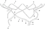
fig. 1 schematically shows a transcatheter valve prosthesis according to an embodiment.
Fig. 2 schematically illustrates a transcatheter valve prosthesis in a collapsed configuration, in accordance with an embodiment.
Fig. 3A and 3B schematically illustrate a transcatheter valve prosthesis according to an embodiment.
Fig. 4A and 4B schematically illustrate close-up views of transcatheter valve prostheses, according to embodiments.
Fig. 5 schematically shows a tubular body of a transcatheter valve prosthesis according to an embodiment.
Fig. 6 schematically shows a tubular body of a transcatheter valve prosthesis according to an embodiment.
Fig. 7 schematically shows a tubular body of a transcatheter valve prosthesis according to an embodiment.
Fig. 8 schematically shows a close-up of a tubular body of a transcatheter valve prosthesis, according to an embodiment.
Fig. 9 schematically illustrates a transcatheter valve prosthesis, according to an embodiment.
Fig. 10 schematically illustrates a transcatheter valve prosthesis, according to an embodiment.
Fig. 11 schematically shows a tubular body of a transcatheter valve prosthesis according to an embodiment.
Fig. 12 schematically shows a tubular body of a transcatheter valve prosthesis according to an embodiment.
Fig. 13A and 13B schematically illustrate a transcatheter valve prosthesis according to an embodiment.
Fig. 14 schematically shows a close-up of a tubular body of a transcatheter valve prosthesis, according to an embodiment.
Fig. 15 schematically illustrates a transcatheter valve prosthesis implanted in a patient, according to an embodiment.
Figure 16 schematically illustrates a transcatheter valve prosthesis implanted in a patient, according to an embodiment.
Detailed Description
The following detailed description refers to the accompanying drawings that show, by way of illustration, specific details in which the disclosed embodiments may be practiced. Other embodiments may be utilized and structural and logical changes may be made without departing from the scope of the present disclosure. The various embodiments are not necessarily mutually exclusive, and aspects of embodiments may be combined with one or more aspects of other embodiments to form additional embodiments.
The disclosed embodiments are directed to a transcatheter valve prosthesis 1 for functionally replacing a native heart valve of a patient in a connecting channel. The native heart valve of the patient may be, for example, a mitral valve or a tricuspid valve. The transcatheter valve prosthesis 1 may be used as a prosthetic replacement valve for a native valve of a patient.
As shown in fig. 1, transcatheter valve prosthesis 1 includes a radially self-expandable tubular body 5 extending along a longitudinal axis 20, the radially self-expandable tubular body having an inflow end 10 and an outflow end 15 (depending on the direction of blood flow when the system is implanted in a patient). In some embodiments, the tubular body 5 may be balloon expandable. The tubular body 5 may comprise a peripheral portion 3 formed by a mesh structure, which is delivered in the patient via a delivery catheter. The mesh structure of the tubular body 5 may comprise a plurality of struts 9 formed from a superalloy and/or a shape memory alloy comprising nickel, titanium and/or a noble metal (e.g., gold). In some embodiments, the tubular body 5 is formed from a nickel titanium alloy. In other embodiments, the tubular body 5 is formed from a polymer comprising polyvinyl chloride, polystyrene, polypropylene, and/or another polymer. For example, the tubular body 5 may be formed from one or more bioabsorbable polymers.
The tubular body 5 may be substantially cylindrical. The outflow end 15 of the tubular body 5 may also comprise a frustoconical shape inclined radially outwards. Alternatively, the outflow end 15 of the tubular body 5 may taper inwardly. Furthermore, fig. 1 to 16 show various configurations of the struts 9 of the tubular body 5. Accordingly, further modifications of the structure and configuration of the strut 9 are within the scope of the present disclosure.
As shown in fig. 1, one or more retaining rings 4 may be connected to the peripheral portion 3 at the inflow end 10 of the tubular body 5. The retaining ring 4 may assist in the delivery and removal of the valve prosthesis 1 in the patient.
The tubular body 5 may comprise an external pre-formed groove 7, which is open to the radial outside of the tubular body 5. The preformed groove 7 may be a channel-defining depression in the web structure of the tubular body 5. As shown in fig. 1, the preformed groove 7 may extend around the entire outer circumference of the tubular body 5. In other embodiments, the preformed groove 7 may extend over less than the entire outer circumference of the tubular body 5. The preformed groove 7 may be a continuous, uninterrupted groove or may be an interrupted groove having, for example, two or more groove portions. In some embodiments, the preformed groove 7 may be located at an axial distance along the axis 20 from the inflow end 10 and the outflow end 15 of the tubular body 5. Thus, the preformed groove 7 may be axially spaced from the proximal and distal most ends of the tubular body 5.
The pre-formed groove 7 may be defined by a protrusion (not shown) protruding outwardly from the tubular body 5. Thus, in some embodiments, the tubular body 5 may comprise a first set of protrusions arranged above the preformed groove 7 in the inflow direction, and a second set of protrusions arranged below the preformed groove 7 in the outflow direction. Thus, the first and second set of projections may surround the top and bottom portions of the preformed groove 7. The first and second sets of projections may face each other. Additionally, the first and second sets of projections may be members configured to pierce tissue, such as staples, triangular projections, barbs, or the like.
The tubular fabric 25 may be disposed on the outer surface of the tubular body 5 such that the fabric 25 has an inflow end 30 and an outflow end 35. The fabric 25 may cover the entire outer surface of the peripheral portion 3 of the tubular body 5, or only a portion of the outer surface of the peripheral portion 3. As shown in fig. 1, the fabric 25 may be disposed within the preformed groove 7 such that the fabric 25 follows the contour of the preformed groove 7. The fabric 25 may be loosely or tightly arranged on the tubular body 5. As discussed further below, the capture member 150 can be disposed about the tubular body 5. The fabric 25 can be disposed on the tubular body 25 such that the fabric is in a loose state before the trapping member 150 is disposed around the tubular body 25. Thus, the trap member 150 can cause the web 25 to move into the preformed groove, placing the web 25 under tension.
The fabric 25 may be formed from a polymeric material including, for example, a polyester fabric (e.g., or other PTFE graft material). Additionally or alternatively,
 fabric 25 may be formed from a pericardial and/or metal mesh material (e.g., a metal mesh formed from a nickel-titanium alloy). In some embodiments, the fabric 25 may contain one or more segments of material. For example, the fabric 25 may include two, four, or six segments of material. The segments may be spaced apart so as to be adjacent segmentsWith a gap provided therebetween. Alternatively or additionally, some or all of the adjacent segments may overlap. The web 25 may comprise one layer of material or a plurality of layers of material. In some embodiments, the fabric 25 may include a coating or a liner.
The fabric 25 may be attached to the tubular body 5 by any known securing mechanism. For example, the fabric 25 and the tubular body 5 may be secured by an adhesive and/or surgical suture. As shown in fig. 1 and 2, the fabric 25 may be configured to assume a deployed expanded configuration and a contracted configuration with the tubular body 5. Accordingly, the fabric 25 can expand and contract based on the state of the tubular body 5.
The tubular body 5 can be coupled to the prosthetic heart valve 40 such that at least a portion of the valve 40 extends distally beyond the outflow end 15 of the tubular body 5 (fig. 3A). As shown in fig. 3B, the valve 40 can include a plurality of valve leaflets 45. The valve 40 may be used as a prosthetic replacement for a native heart valve (e.g., mitral and/or tricuspid) of a patient.
The tubular body 5 can be coupled to the valve 40 such that the peripheral edges 50 of the leaflets 45 are directly connected to the outflow ends 35 of the fabric 25 (fig. 4A and 4B). Thus, as shown in fig. 3A, 4A and 4B, the valve leaflets 45 can extend further in the outflow direction than the outflow end 15 of the tubular body 5. The valve leaflets 45 may also be distal to the preformed groove 7 in the outflow direction. The peripheral edge 50 of the leaflets 45 can axially overlap the outflow end 35 of the fabric 25 such that the peripheral edge 50 is connected to the outflow end 35 by one or more surgical sutures 55. Additionally or alternatively, the peripheral edge 50 can be attached to the outflow end 35 by any suitable securing mechanism (e.g., adhesive, clips, clamps, etc.).
Furthermore, the tubular body 5 may be directly connected to the fabric 25, such that the struts 9 of the tubular body 5 are connected to the fabric 25 by one or more surgical sutures 55 (fig. 4A). Additionally or alternatively, the struts 9 may be connected to the fabric 25 by any suitable securing mechanism (e.g., adhesive, clips, clamps, etc.). Thus, as shown in fig. 4A, the valve leaflets 45 are not directly connected to the tubular body 5. Thus, the valve 40 is also not directly connected to the tubular body 5. Alternatively, the valve 40 is indirectly connected to the tubular body 5 by the fabric 25.
As shown in fig. 4A and 4B, the peripheral edges 50 of the valve leaflets 45 can be disposed on the inflow side of the valve 40. Thus, the peripheral edges 50 of the valve leaflets 45 can be directly connected to the outflow ends 35 of the fabric 25 such that the peripheral edges 50 of the valve leaflets 45 axially overlap the outflow ends 35 of the fabric 25 to provide a direct connection between the valve 40 and the fabric 25.
Furthermore, the struts 9 of the tubular body 5 that are directly connected to the fabric 25 may be struts 12 located at the outflow end 15 of the tubular body 5 (fig. 1 and 4A). The struts 12 may overlap the fabric 25 in the axial direction. Thus, the struts 12 may provide a direct connection between the tubular body 5 and the fabric 25.
In some embodiments, the connection between the fabric 25 and the struts 12 of the tubular body 5 can be located closer to the inflow end 10 of the tubular body 5 than the connection between the fabric 25 and the peripheral edges 50 of the valve leaflets 45 (fig. 4A and 4B). Thus, the connection between the fabric 25 and the tubular body 5 may be proximal to the connection between the fabric 25 and the valve 40 (fig. 4A and 4B). It is also contemplated that the connection between the fabric 25 and the tubular body 5 may be at the same axial location as the connection between the fabric 25 and the valve 40, such that the connections axially overlap.
In addition, as shown in fig. 4A and 4B, the peripheral edges 50 of the valve leaflets 45 can be disposed distal to the struts 12 in the outflow direction. Thus, the peripheral edge 50 may be arranged distally of the peripheral portion 3 of the tubular body 5 in the outflow direction. Thus, the peripheral edges 50 of the valve leaflets 45 may not radially overlap the peripheral portion 3 of the tubular body 5.
As discussed above, the peripheral edge 50 of the valve 40 is connected to the outflow end 35 of the fabric 25 such that the valve leaflets 45 extend further in the outflow direction than the outflow end 15 of the tubular body 5 (fig. 3A and 4B). Thus, the valve 40 may not axially overlap the peripheral portion 5 of the tubular body 5, and the tubular body 5 advantageously has an increased compression capacity. Thus, the tubular body 5 can be compressed further than conventional valve prostheses, allowing the tubular body 5 to adopt a smaller delivery profile.
In other alternative embodiments, the valve 40 may be directly connected to the outflow end 15 of the tubular body 5 by one or more surgical sutures 55. Additionally or alternatively, the valve 40 can be directly connected to the outflow end 15 of the tubular body 5 by any suitable securing mechanism (e.g., adhesive, clips, clamps, etc.). In these embodiments, the valve leaflets 45 can be directly connected to the struts 12 such that the valve leaflets 45 are connected to the outflow end 15 of the tubular body 5. Additionally, the valve leaflets 45 can be directly connected to the fabric 25, and/or the fabric 25 can be directly connected to the struts 12.
As shown in fig. 4A and 4B, the outflow end 35 of the fabric 25 may not extend distally beyond the peripheral edge 50 of the leaflets 45 in the outflow direction. Thus, the outflow end 35 may terminate at the location of the peripheral edge 50. Although the outflow end 35 of the fabric 25 may extend distally beyond the struts 12 of the tubular body 5, the outflow end 35 of the fabric 25 does not encircle the struts 12. Thus, the fabric 25 does not encircle the outflow end 15 of the tubular body 5. In some embodiments, the outflow end 35 of the fabric 25 only partially surrounds the struts 12 (and, thus, partially surrounds the outflow end 15 of the tubular body 5). In these embodiments, the outflow end 35 of the fabric 25 does not completely encircle the strut 12. In other alternative embodiments, the outflow end 35 of the fabric 25 completely surrounds the outflow end 15 of the tubular body 5.
As shown in fig. 5, the struts 12 of the tubular body 5 may form a plurality of arched beams 60 at the outflow end 15 of the tubular body 5. The beam 60 may be directly connected to the fabric 25, as discussed above. Thus, the beams 60 may be connected to the fabric 25 such that the valve leaflets 45 extend further in the outflow direction than the beams 60, as discussed above. Each beam 60 may be directly connected to an adjacent beam 60 such that a plurality of beams 60 extend around the entire circumferential length of the tubular body 5 at the outflow end 15. In addition, adjacent beams 60 may be directly attached such that the beams 60 are continuous along the entire circumference of the tubular body 5 at the outflow end 15.
The tubular body 5 may comprise a proximal-most end 13 at the inflow end 10 and a distal-most end 14 at the outflow end 15. As shown in fig. 5-7, the arched beam 60 may form the distal-most end 14 of the tubular body 5. Further, the beams 60 may each include a first end 67 and a second end 69, such that the second end 69 is distal to the first end 67 in the outflow direction. The first and second ends 67, 69 may form an arch of the beam 60. In addition, the second end 69 can form a commissure attachment region for attachment to the valve leaflet 45.
As shown in fig. 5-7, for example, the second end 69 of the beam 60 may be connected to one or more retaining members 78. Thus, the distal-most end 14 of the tubular body 5 may also be connected to the holding member 78. In some embodiments, the retaining member 78 is distal to the peripheral portion 3 of the tubular body 5 in the outflow direction. The retention component 78 may assist in anchoring the tubular body 5 within the patient. The fabric 25 may be disposed on the tubular body 5 such that the fabric 25 is not disposed on the holding member 78. In some embodiments, the fabric 25 may not extend further in the outflow direction than the distal-most end 14 of the tubular body 5. Thus, the fabric 25 may not extend further than the retention feature 78.
In some embodiments, each valve leaflet 45 can be supported by only two beams 60 of the plurality of beams 60. Thus, for example, as shown in fig. 3B and 5, a single valve leaflet 45 can be supported by the first beam 61 and the second beam 63. Each valve leaflet 45 may be supported by beams 61 and 63 such that valve leaflet 45 is directly connected to fabric 25 that is directly connected to beams 61 and 63, as discussed above. Thus, the connection between the valve leaflets 45, the fabric 25 and the beams 60 provides support between the beams 60 and the valve leaflets 45. In other embodiments, each valve leaflet 45 can be supported by two, three, or more beams 60. While six beams are shown in fig. 5-7, it is also contemplated that more or fewer beams may be used. Thus, the tubular body 5 may comprise at least six beams 60.
As shown in fig. 5-7, the connection point 65 may directly couple the inflow end 10 of the tubular body 5 with the beam 60. All direct coupling between the inflow end 10 and the beam 60 may be provided by the connection point 65 only. In the embodiment of fig. 5 to 7, three connection points 65 are provided. The number of connection points 65 can be equal to the number of valve leaflets 45, as shown in fig. 3B. Thus, in other embodiments, four, five, or more attachment points 65 may be provided, depending on the number of valve leaflets 45. It is also contemplated that the number of connection points 65 is a multiple of the number of valve leaflets. In some embodiments, as shown in fig. 5-7, the first end 67 of the beam 60 provides the connection point 65.
By providing a direct coupling between the inflow end 10 and the beam 60, the connection point 65 may provide a decorrelation of movement between the inflow end 10 of the tubular body 5 and the beam 60. Thus, the connection point 65 may separate axial and radial movement between the inflow end 10 and the beam 60. For example, the connection point 65 may be configured to attenuate movement of the inflow end 10 of the tubular body 5. Thus, movement of the inflow end 10 is not fully transferred to the beam 60. Alternatively, the connection point 65 may absorb movement of the inflow end 10, thereby providing a decorrelation effect. In some embodiments, the connection point 65 absorbs all movement of the inflow end 10. In other embodiments, the connection point 65 absorbs only a portion of the movement of the inflow end 10.
As shown in fig. 5-7, the inflow end 10 of the tubular body 5 comprises struts 9 having peaks 70 and valleys 75. The peaks 70 are disposed proximally from the valleys 75 such that the valleys 75 are positioned closer to the outflow end 15 of the tubular body 5 than the peaks 70. Further, the peaks 70 and valleys 75 may form the proximal-most end 13 of the tubular body 5.
In some embodiments, the peaks 70 and valleys 75 may be configured such that movement of the peaks 70 radially inward may cause the valleys 75 to splay radially outward (fig. 8). For example, upon implantation of the tubular body 5 into a patient, the atrial wall of the patient may push the peaks 70 radially inward (due to the normal systolic movement of the native valve of the patient). This causes the peaks 70 to deform and move radially inward as shown in fig. 8. Thus, inward movement of the peaks 70 causes the valleys 75 to deform and move radially outward. The deformation of the valleys 75 further urges the inflow end 10 radially outward into contact with the atrial wall of the patient, thereby enhancing the sealing effect of the inflow end 10 within the patient.
When the fabric 25 is disposed on the tubular body 5, as discussed above, the radially inward movement of the peaks 70 may cause the valleys 75 and fabric 25 to splay radially outward. Accordingly, fabric 25 is pushed further to contact the patient's atrial wall along with valleys 70 to further increase the sealing effect of tubular body 5 within the patient.
As shown in fig. 1 and 9, for example, the outflow end 15 of the tubular body 5 may comprise a beam 60 and a proximal section 80. The beam 60 and the proximal section 80 may be arranged at the distal end of the preformed groove 7 in the outflow direction. The proximal section 80 may also be disposed distal to the peaks 70 and valleys 75 in the outflow direction. Furthermore, the beam 60 may be arranged distal to the proximal section 80 in the outflow direction. Thus, as shown in fig. 10, radially inward movement of the proximal segments 80 may cause the inflow end 10 of the tubular body 5 to flare radially outward. For example, natural movement of the native valve of the patient may cause inward compression of the tubular body 5. More specifically, in some examples, the native valve of the patient may cause inward compression of the valve leaflets 45, which in turn may cause inward compression of the tubular body 5. Thus, such compression may result in compressing the proximal section 80 radially inward. Due to the structure of the tubular body 5, movement of the proximal section 80 radially inward causes the inflow end 10 to flare radially outward. The outward movement of the inflow end 10 may increase the sealing effect between the inflow end 10 and the atrial wall of the patient, thus advantageously providing a tighter seal between the tubular body 5 and the atrial wall of the patient. Further, the beam 60 may not move as the proximal section 80 moves radially inward and the inflow end 10 flares radially outward. Thus, the connection point 65 may decouple such movement of the proximal section 80 from the beam 60.
As shown in fig. 9 and 10, the connection point 65 may be provided in the proximal section 80. Alternatively, the connection point 65 may be disposed distally of the proximal section 80 in the outflow direction. Furthermore, in some embodiments, the valve leaflets 45 can extend completely distal of the proximal section 80 in the outflow direction. In other embodiments, the valve leaflets 45 can axially overlap the proximal section 80.
Fig. 11 shows an additional configuration of the struts 9, wherein the inflow end 10 of the tubular body 5 comprises an S-shaped strut 9. The S-shaped struts may be directly connected to the peaks 70 such that the peaks 70 and valleys 75 are disposed above the S-shaped struts in the inflow direction when the tubular body 5 is in the expanded state. The S-shaped struts may each form a decorrelation portion that separates movement between the proximal-most end 13 of the tubular body 6 and the outflow end 15 of the tubular body 5. Thus, the S-shaped struts may be configured to pressurize and compress in response to movement of the inflow end 10 or the outflow end 15. Thus, movement from one end of the tubular body 5 is not transferred/propagated to the other end of the tubular body 5 as the S-shaped struts expand and/or compress. The S-shaped struts may be arranged completely at the proximal end of the preformed groove 7 in the inflow direction.
In some embodiments, the tubular body 5 may include a motion bumper component 90 (fig. 11-13B) integrated into the tubular body 5. The motion damper member 90 may comprise one or more struts 9 formed, for example, in a drop shape (fig. 11) or a triangular shape (fig. 12). The motion damper member 90 may be integral with the remainder of the tubular body 5 such that the tubular body 5 forms a unitary member. Additionally, fabric 25 may be disposed on the outer surface of motion bumper component 90.
Movement of the valve leaflets 45 within the patient can cause the tubular body 5 to also move within the patient. More specifically, the valve leaflets 45 can move inward and outward when replacing the function of a native valve in a patient. Such movement may result in, for example, pushing the outflow end 15 of the tubular body 5 radially inward and outward relative to the atrial wall of the patient. Such movement of the outflow end 15 also causes the fabric 25 to be pushed radially inward and outward relative to the atrial wall of the patient. This movement of the fabric 25 against the native valve of the patient may cause friction and wear to the fabric 25. Furthermore, the tubular body 5 may also be subject to friction and wear due to constant contact with the native valve of the patient.
The motion bumper member 90 may create a shock absorber effect to reduce such friction and wear to the fabric 25 and the tubular body 5. For example, as shown in fig. 13A and 13B, when the outflow end 15 of the tubular body 5 moves radially inward due to movement of the valve leaflets 45, the motion bumper member 90 may be configured not to move radially inward with the outflow end 15. Rather, the motion damper member 90 may move radially outward or may remain in place to react to inward movement of the outflow end 15. Thus, when the outflow end 15 is moved radially inward, the motion bumper member 90 can be pushed radially outward against the fabric 25 and against the native valve leaflets of the patient. Such radially outward urging of the motion bumper member 90 may produce a bumper effect. Thus, when the outflow end 15 and the fabric 25 are pushed from a radially inward position to a radially outward position (due to the movement of the valve leaflets 45), the motion bumper member 90 provides a cushioning effect that softens the radially outward force of the outflow end 15 and the fabric 25 against the native valve leaflets of the patient, because the motion bumper member 90 has been projected outward.
Thus, the motion bumper member 90 can absorb friction and wear to the tubular body 5 due to movement of the valve leaflets 45. Thus, the motion damper component 90 may advantageously make the tubular body 5, and particularly the beam 60, more durable. In addition, the motion bumper component 90 can absorb friction and wear to the fabric 25 due to movement of the valve leaflets 45. Thus, the motion bumper component 90 may also advantageously make the fabric 25 more durable.
Fig. 13A shows a neutral state of the tubular body 5, and fig. 13B shows a state of the tubular body 5 in which the outflow end 15 is moved radially inward and the motion damper member 90 is moved radially outward. The structure and/or location of the motion-dampener component 90 may be such that the motion-dampener component 90 is able to move radially outward or stay in place in response to inward movement of the outflow end 15. As shown in fig. 11-13B, a motion bumper member 90 may be disposed adjacent to the beam 60 of the preformed groove 7 and distal to the preformed groove in the outflow direction. A motion bumper member 90 may be disposed within the proximal section 80. Additionally, the strut width of the motion bumper component 90 may be less than the strut width of the beam 60. Thus, the motion bumper member 90 may have sufficient flexibility to move radially outward or stay in its position, as discussed above.
In some embodiments, the motion bumper component 90 can be located at the same cross section in the radial direction as the valve leaflets 45. Thus, the motion bumper component 90 and the valve leaflets 45 can axially overlap along the longitudinal axis 20. Additionally, the motion bumper component 90 may be located at least partially at the same cross-section in the radial direction as the connection point 65. Thus, the motion bumper component 90 and the connection point 65 may axially overlap along the longitudinal axis 20.
Fig. 14 shows an embodiment in which the tubular body 5 comprises struts 9 having different thicknesses. Thus, for example, the struts 9 may comprise a relatively smaller thickness 100 and a relatively larger thickness 110. Further, the strut 9 may be bent to form the first unit 120 and the second unit 130. As shown in fig. 14, the first cells 120 are formed from struts having a relatively small thickness 100 and the second cells 130 are formed from struts having a relatively large thickness 110. In addition, the third unit 140 may be disposed between the first unit 120 and the second unit 130. The third cell may be formed of struts having a relatively small thickness 100 and struts having a relatively large thickness 110.
The first, second and third cells 120, 130, 140 may be configured to open and expand in unison when the tubular body 5 is opened and expanded. Thus, a strut having a relatively smaller thickness 100 and a relatively larger thickness 110 allows all of the cells 120, 130, 140 to open together at the same rate. In contrast, in conventional prosthetic devices, some strut units may require less outward force to open, depending on their placement in the mesh structure of the prosthetic device. Thus, some strut units may open more easily and quickly than others. This results in non-uniform expansion and opening of the prosthesis. For example, a more easily opened strut unit may be fully opened before a more difficult to open strut unit. Such non-uniform expansion may result in inaccurate placement of the prosthetic device and may alter the performance of the prosthetic valve. Because the cells 120, 130, 140 open together at the same rate, the valve prosthesis 1 expands uniformly during manufacture (e.g., during its thermoforming process). Thus, the units 120, 130, 140 provide a prosthetic device that is easier to manufacture than conventional prosthetic devices.
In the embodiment of fig. 14, struts having a relatively greater thickness 110 may be placed on the tubular body 5 at locations that are relatively easier to open. Struts having a relatively small thickness 100 may be placed on the tubular body 5 at locations that are relatively more difficult to open. Thus, the thickness of the struts can balance the ease of opening to provide a consistent expansion across all cells of the tubular body 5.
All embodiments of the valve prosthesis 1 may comprise positioning and/or orienting means (not shown) to facilitate relative and/or absolute positioning of the tubular body 5. These means may comprise passive markers fixedly attached to the tubular body 5. The passive marker may be made of a material different from the material of the tubular body 5 in order to improve contrast during medical imaging, for example using magnetic resonance or X-ray based imaging techniques. The passive marker may, for example, be made of a highly radio-opaque material, thereby allowing the relative and/or absolute position of the components of the valvular prosthesis 1 with respect to the body of the patient to be accurately acquired.
The structure of the valvular prosthesis 1 allows a smaller external profile to be achieved than with conventional prostheses. Thus, for example, the valve prosthesis 1 may be sized according to human anatomy and may be compressed into a 26FID tubular catheter for delivery within a patient. In addition, because the valve leaflets 45 extend distally beyond the tubular body 5, the size of the frame of the tubular body 5 required to support the valve 40 can be reduced. For example, the number of struts 9 may be reduced, thereby providing a more flexible structure. In addition, the configuration of the valve prosthesis 1 provides better geometric stability of the valve leaflets 45 compared to conventional prostheses.
As shown in fig. 15, the valve prosthesis 1 may be deployed to a patient via a catheter. A method of delivering the valve prosthesis 1 can include delivering the tubular body 5 and the valve 40 from a delivery catheter. Next, the tubular body 5 and the valve 40 may be expanded so that the beams 60 of the tubular body 5 are arranged against the tissue of the patient's connecting channel between the atrium and ventricle of the heart. Thus, for example, the valve prosthesis 1 may be delivered to a defective mitral or tricuspid valve of a patient in order to restore operability. The valve prosthesis 1 can be delivered to the patient such that the preformed groove 7 is located on the ventricular side of the native valve's annulus (e.g., at a distance from the native valve annulus).
For placing the valvular prosthesis 1 within the heart valve of a patient, the following method may be applied: (1) arterial retrograde approach via aorta into the heart chamber; (2) access through veins and by puncturing the atrial septum (transseptal approach); (3) via puncturing the apex of the heart (transapical approach); (4) via puncturing the atrial wall from outside the heart; (5) arterial access (e.g., access from the femoral artery by puncture in the groin); (6) directly through the superior vena cava and into the right atrium (e.g., for tricuspid valve replacement); or (7) any other method known to the skilled person.
For a functional replacement of a heart valve of a patient, the valve prosthesis 1 can be fixed relative to the connecting channel wall structure of the patient such that the exterior of the valve prosthesis 1 is sealed against the blood flow. To this end, the tissue of the connecting channel wall structure of the patient adjacent to the preformed groove 7 may be forced or placed within the preformed groove 7.
The method may further comprise advancing the capture member 150 around the tubular body 5 and around the preformed groove 7. Thus, the trapping member 150 can trap portions of the native valve leaflets 160 and/or chords 170 in the preformed groove 7. This may help to secure the tubular body 5 within the patient. The trapping member 150 may comprise a whole ring or a partial ring. In addition, the trapping member 150 may be moved around the tubular body 5 after the tubular body 5 is completely expanded or when only the tubular body 5 is partially expanded. The capture member 150 may be loosely disposed within the preformed groove such that an interference fit between the capture member 150 and the preformed groove 7 secures the tubular body 5 in place. Thus, the trapping component 150 can be used to anchor the valve prosthesis 1 in the patient. In other embodiments, the capture component 150 can apply an inward radial force to the tubular body 5 to anchor the valvular prosthesis 1 within the patient. Thus, in this embodiment, the trapping member 150 can apply a frictional force to the native valve leaflets 160 and/or chords 170.
The capture component 150 can comprise a delivery configuration within a delivery catheter, and a deployed configuration in which the capture component 150 is deployed from the delivery catheter. In an embodiment, the capture component 150 can be biased in the deployed configuration. For example, the capture member 150 may comprise a shape memory alloy, such as a nickel titanium alloy or a nickel titanium alloy-based alloy.
In some embodiments, the elongate outer member 180 may also be advanced around the tubular body 5 and around the preformed groove 7. The elongate outer member 180 may surround the tubular body 5 after the tubular body 5 has been fully expanded or when the tubular body 5 is only partially expanded. The elongate outer member 180 can force the native valve leaflets 160 and/or chords 170 of the patient into the preformed groove 7. The capture member 150 can then be positioned on and along the elongate outer member 180 so as to advance the capture member 150 around the tubular body 5 and into the preformed groove 7. After the trapping member 150 is disposed around the tubular body 5, the elongate outer member 180 can then be removed from the patient. After the elongated outer member 180 is removed from the patient, the capture member 150 can maintain the native valve leaflets 160 and/or chords 170 of the patient in the preformed groove 7.
In some embodiments, the elongate outer member 180 may be a guidewire. The elongated outer member 180 may have a diameter smaller than the diameter of the trapping member 150.
The disclosed method of using the valve prosthesis 1 may result in securing the tubular body 5 in the connection channel wall structure of the patient with minimal occlusion of the patient's native valve.
The disclosed embodiments also encompass a method for manufacturing the valvular prosthesis 1. The method of manufacture may include directly connecting the peripheral edge 50 of the valve 40 with the outflow end 35 of the fabric 25 to form a subassembly. Next, the tubular body 5 may be slid into the subassembly. Subsequently, the tubular body 5 can be connected to the subassemblies to form an assembly such that the valve leaflets 45 extend further in the outflow direction than the outflow end 15 of the tubular body 5. The tubular body 5 can be connected directly to the subassembly by connecting the outflow end 15 of the tubular body 5 with the fabric 25. As shown in fig. 4A and 4B, the fabric 25 may be directly connected to the peripheral edge 50 and directly to the tubular body 5 by one or more surgical sutures 55.
Claims (14)
1. A heart valve system, the heart valve system comprising:
a radially self-expandable tubular body having an inflow end and an outflow end;
a valve coupled to the tubular body, the valve including a plurality of valve leaflets; and
a tubular fabric disposed on an outer surface of the tubular body, the fabric having an inflow end and an outflow end,
wherein the outflow end of the fabric is directly connected to a peripheral edge of the valve,
the peripheral edge of the valve is directly connected to the circumferential outflow end of the tubular body, such that the valve extends in the outflow direction from the outflow end of the tubular body to the free distal end of the valve,
the valve leaflets of the valve extend further in the outflow direction than the outflow end of the tubular body, allowing the valve system to assume a smaller delivery profile.
2. The system of claim 1, wherein the fabric is directly connected to the tubular body at the outflow end of the tubular body.
3. The system of claim 2, wherein the fabric is directly connected to the peripheral edge of the valve and directly to the tubular body by one or more surgical sutures.
4. The system of claim 1, wherein the fabric does not encircle the outflow end of the tubular body.
5. The system of claim 1, wherein:
the tubular body comprises a peripheral portion and one or more retention members, and
the fabric surrounds the entire outer surface of the peripheral portion of the tubular body.
6. The system of claim 5, wherein the peripheral edge of the valve is disposed distally of the peripheral portion of the tubular body in the outflow direction.
7. The system of claim 5, wherein the peripheral edge of the valve does not radially overlap the peripheral portion of the tubular body.
8. The system of claim 1, further comprising a capture member configured to form at least a partial ring that surrounds the tubular body to capture portions of native valve leaflets and/or chordae tendinae.
9. The system of claim 1, wherein the tubular body and the fabric are configured to assume an expanded configuration and a contracted configuration.
10. A method for manufacturing a heart valve, the method comprising:
directly connecting the peripheral edge of the valve with the outflow end of the tubular fabric to form a subassembly;
subsequently, sliding a radially self-expandable tubular body into the subassembly; and
subsequently, the tubular body is connected to the subassemblies to form an assembly such that valve leaflets of the valve extend further in the outflow direction than the outflow end of the tubular body, a peripheral edge of the valve being directly connected to the circumferential outflow end of the tubular body such that the valve extends in the outflow direction from the outflow end of the tubular body to the free distal end of the valve, thereby allowing the heart valve to assume a smaller delivery profile.
11. The method of claim 10, further comprising directly connecting an outflow end of the tubular body with the fabric to form the subassembly.
12. The method of claim 11, further comprising connecting the fabric directly to the peripheral edge of the valve and directly to the tubular body by one or more surgical sutures.
13. The method of claim 10, wherein the fabric does not encircle the outflow end of the tubular body.
14. The method of claim 10, wherein:
the tubular body comprises a peripheral portion and one or more retention members, and
the fabric surrounds the entire outer surface of the peripheral portion of the tubular body.
Applications Claiming Priority (3)
| Application Number | Priority Date | Filing Date | Title |
|---|---|---|---|
| US15/343,694 US11376121B2 (en) | 2016-11-04 | 2016-11-04 | Transcatheter valve prosthesis |
| US15/343,694 | 2016-11-04 | ||
| PCT/IB2017/001555 WO2018083541A1 (en) | 2016-11-04 | 2017-11-06 | Transcatheter valve prosthesis |
Publications (2)
| Publication Number | Publication Date |
|---|---|
| CN110035713A CN110035713A (en) | 2019-07-19 |
| CN110035713B true CN110035713B (en) | 2022-03-08 |
Family
ID=60972253
Family Applications (1)
| Application Number | Title | Priority Date | Filing Date |
|---|---|---|---|
| CN201780075189.2A Active CN110035713B (en) | 2016-11-04 | 2017-11-06 | Transcatheter valve prosthesis |
Country Status (7)
| Country | Link |
|---|---|
| US (2) | US11376121B2 (en) |
| EP (1) | EP3534841B1 (en) |
| JP (1) | JP7175268B2 (en) |
| CN (1) | CN110035713B (en) |
| AU (1) | AU2017353942B2 (en) |
| CA (1) | CA3042841A1 (en) |
| WO (1) | WO2018083541A1 (en) |
Families Citing this family (30)
| Publication number | Priority date | Publication date | Assignee | Title |
|---|---|---|---|---|
| US20090276040A1 (en) * | 2008-05-01 | 2009-11-05 | Edwards Lifesciences Corporation | Device and method for replacing mitral valve |
| US9554897B2 (en) | 2011-04-28 | 2017-01-31 | Neovasc Tiara Inc. | Methods and apparatus for engaging a valve prosthesis with tissue |
| US9308087B2 (en) | 2011-04-28 | 2016-04-12 | Neovasc Tiara Inc. | Sequentially deployed transcatheter mitral valve prosthesis |
| US9345573B2 (en) | 2012-05-30 | 2016-05-24 | Neovasc Tiara Inc. | Methods and apparatus for loading a prosthesis onto a delivery system |
| US10561509B2 (en) | 2013-03-13 | 2020-02-18 | DePuy Synthes Products, Inc. | Braided stent with expansion ring and method of delivery |
| EP3389557B1 (en) | 2015-12-15 | 2022-07-13 | Neovasc Tiara Inc. | Transseptal delivery system |
| US10433952B2 (en) | 2016-01-29 | 2019-10-08 | Neovasc Tiara Inc. | Prosthetic valve for avoiding obstruction of outflow |
| US10292851B2 (en) | 2016-09-30 | 2019-05-21 | DePuy Synthes Products, Inc. | Self-expanding device delivery apparatus with dual function bump |
| US10188514B2 (en) * | 2016-11-04 | 2019-01-29 | Highlife Sas | Transcatheter valve prosthesis |
| US9999502B2 (en) | 2016-11-04 | 2018-06-19 | Highlife Sas | Transcather valve prosthesis |
| CN113893064A (en) | 2016-11-21 | 2022-01-07 | 内奥瓦斯克迪亚拉公司 | Methods and systems for rapid retrieval of transcatheter heart valve delivery systems |
| US11666444B2 (en) | 2017-08-03 | 2023-06-06 | The Regents Of The University Of California | Atrial cage for placement, securing and anchoring of atrioventricular valves |
| CA3073834A1 (en) | 2017-08-25 | 2019-02-28 | Neovasc Tiara Inc. | Sequentially deployed transcatheter mitral valve prosthesis |
| AU2019204522A1 (en) | 2018-07-30 | 2020-02-13 | DePuy Synthes Products, Inc. | Systems and methods of manufacturing and using an expansion ring |
| US10456280B1 (en) | 2018-08-06 | 2019-10-29 | DePuy Synthes Products, Inc. | Systems and methods of using a braided implant |
| CA3115270A1 (en) | 2018-10-05 | 2020-04-09 | Shifamed Holdings, Llc | Prosthetic cardiac valve devices, systems, and methods |
| WO2020082039A1 (en) | 2018-10-19 | 2020-04-23 | Shifamed Holdings, Llc | Adjustable medical device |
| US11737872B2 (en) | 2018-11-08 | 2023-08-29 | Neovasc Tiara Inc. | Ventricular deployment of a transcatheter mitral valve prosthesis |
| WO2020185597A1 (en) | 2019-03-08 | 2020-09-17 | Neovasc Tiara Inc. | Retrievable prosthesis delivery system |
| CN113811265B (en) | 2019-04-01 | 2024-11-29 | 内奥瓦斯克迪亚拉公司 | Prosthetic valve capable of being deployed in a controlled manner |
| CN113924065B (en) | 2019-04-10 | 2026-01-30 | 内奥瓦斯克迪亚拉公司 | Prosthetic valve with natural blood flow |
| WO2020236931A1 (en) | 2019-05-20 | 2020-11-26 | Neovasc Tiara Inc. | Introducer with hemostasis mechanism |
| EP3986332A4 (en) | 2019-06-20 | 2023-07-19 | Neovasc Tiara Inc. | Low profile prosthetic mitral valve |
| US11484407B2 (en) * | 2020-01-07 | 2022-11-01 | Highlife Sas | Transcatheter valve prosthesis |
| EP4114313B1 (en) * | 2020-03-03 | 2025-10-01 | Shifamed Holdings, LLC | Prosthetic cardiac valve devices, systems |
| AU2021273213A1 (en) * | 2020-05-15 | 2022-12-22 | ReValve Solutions Inc. | Devices, systems, and methods for a collapsible and expandable replacement heart valve |
| US12329635B2 (en) * | 2020-12-04 | 2025-06-17 | Shifamed Holdings, Llc | Flared prosthetic cardiac valve delivery devices and systems |
| EP4262628A1 (en) * | 2020-12-18 | 2023-10-25 | Cephea Valve Technologies, Inc. | Collapsible gasket seal for heart valve |
| CN217987802U (en) * | 2021-06-11 | 2022-12-09 | 爱德华兹生命科学公司 | Prosthetic heart valve |
| WO2023249682A1 (en) * | 2022-06-20 | 2023-12-28 | St. Jude Medical, Cardiology Division, Inc. | Fabric suture valve suspension system |
Citations (3)
| Publication number | Priority date | Publication date | Assignee | Title |
|---|---|---|---|---|
| CN101505686A (en) * | 2006-06-20 | 2009-08-12 | 奥尔特克斯公司 | Prosthetic heart valves, support structures and systems and methods for implanting the same |
| CN102639179A (en) * | 2009-12-04 | 2012-08-15 | 爱德华兹生命科学公司 | Prosthetic valve for replacing mitral valve |
| WO2013059747A1 (en) * | 2011-10-19 | 2013-04-25 | Foundry Newco Xii, Inc. | Prosthetic heart valve devices, prosthetic mitral valves and associated systems and methods |
Family Cites Families (61)
| Publication number | Priority date | Publication date | Assignee | Title |
|---|---|---|---|---|
| US6231598B1 (en) | 1997-09-24 | 2001-05-15 | Med Institute, Inc. | Radially expandable stent |
| US6395019B2 (en) | 1998-02-09 | 2002-05-28 | Trivascular, Inc. | Endovascular graft |
| US6264700B1 (en) * | 1998-08-27 | 2001-07-24 | Endonetics, Inc. | Prosthetic gastroesophageal valve |
| US6139575A (en) | 1999-04-02 | 2000-10-31 | Medtronic, Inc. | Hybrid mechanical heart valve prosthesis |
| US6325825B1 (en) | 1999-04-08 | 2001-12-04 | Cordis Corporation | Stent with variable wall thickness |
| US6458153B1 (en) | 1999-12-31 | 2002-10-01 | Abps Venture One, Ltd. | Endoluminal cardiac and venous valve prostheses and methods of manufacture and delivery thereof |
| US7195641B2 (en) | 1999-11-19 | 2007-03-27 | Advanced Bio Prosthetic Surfaces, Ltd. | Valvular prostheses having metal or pseudometallic construction and methods of manufacture |
| US6454799B1 (en) | 2000-04-06 | 2002-09-24 | Edwards Lifesciences Corporation | Minimally-invasive heart valves and methods of use |
| US20030109923A1 (en) | 2001-12-12 | 2003-06-12 | Chinn Joseph A. | Polymer heart valve with perforated stent and sewing cuff |
| US7037344B2 (en) * | 2002-11-01 | 2006-05-02 | Valentx, Inc. | Apparatus and methods for treatment of morbid obesity |
| WO2005011535A2 (en) * | 2003-07-31 | 2005-02-10 | Cook Incorporated | Prosthetic valve for implantation in a body vessel |
| US8007528B2 (en) | 2004-03-17 | 2011-08-30 | Boston Scientific Scimed, Inc. | Bifurcated stent |
| WO2005097012A2 (en) * | 2004-03-26 | 2005-10-20 | Satiety, Inc. | Systems and methods for treating obesity |
| JP4912395B2 (en) * | 2005-05-24 | 2012-04-11 | エドワーズ ライフサイエンシーズ コーポレイション | Rapid placement prosthetic heart valve |
| DE102005052628B4 (en) | 2005-11-04 | 2014-06-05 | Jenavalve Technology Inc. | Self-expanding, flexible wire mesh with integrated valvular prosthesis for the transvascular heart valve replacement and a system with such a device and a delivery catheter |
| US20080275550A1 (en) | 2006-02-24 | 2008-11-06 | Arash Kheradvar | Implantable small percutaneous valve and methods of delivery |
| US9572660B2 (en) | 2007-06-04 | 2017-02-21 | St. Jude Medical, Inc. | Prosthetic heart valves |
| EP2192875B1 (en) | 2007-08-24 | 2012-05-02 | St. Jude Medical, Inc. | Prosthetic aortic heart valves |
| ES2571740T3 (en) | 2007-09-26 | 2016-05-26 | St Jude Medical | Collapsible prosthetic heart valves |
| BRPI0819217B8 (en) | 2007-10-25 | 2021-06-22 | Symetis Sa | replacement valve for use within a human body, system for replacing a valve within a human body, and heart valve release system with stent |
| US20110160836A1 (en) * | 2008-06-20 | 2011-06-30 | Vysera Biomedical Limited | Valve device |
| EP4541320A3 (en) | 2008-09-29 | 2025-07-09 | Edwards Lifesciences CardiAQ LLC | Heart valve |
| US20100217382A1 (en) | 2009-02-25 | 2010-08-26 | Edwards Lifesciences | Mitral valve replacement with atrial anchoring |
| US8808366B2 (en) | 2009-02-27 | 2014-08-19 | St. Jude Medical, Inc. | Stent features for collapsible prosthetic heart valves |
| EP2437689B1 (en) | 2009-06-05 | 2023-08-02 | Medtronic ATS Medical Inc. | Flexible commissure structure for attaching valve bioprosthesis |
| US9522062B2 (en) | 2010-02-24 | 2016-12-20 | Medtronic Ventor Technologies, Ltd. | Mitral prosthesis and methods for implantation |
| US9072603B2 (en) | 2010-02-24 | 2015-07-07 | Medtronic Ventor Technologies, Ltd. | Mitral prosthesis and methods for implantation |
| US8795354B2 (en) * | 2010-03-05 | 2014-08-05 | Edwards Lifesciences Corporation | Low-profile heart valve and delivery system |
| EP4052682A1 (en) | 2010-09-01 | 2022-09-07 | Medtronic Vascular Galway | Prosthetic valve support structure |
| JP2013540484A (en) | 2010-09-20 | 2013-11-07 | セント・ジュード・メディカル,カーディオロジー・ディヴィジョン,インコーポレイテッド | Valve leaflet mounting device in foldable artificial valve |
| US8845720B2 (en) | 2010-09-27 | 2014-09-30 | Edwards Lifesciences Corporation | Prosthetic heart valve frame with flexible commissures |
| ES2781788T5 (en) * | 2010-10-05 | 2025-08-11 | Edwards Lifesciences Corp | Prosthetic heart valve |
| EP3964176B1 (en) | 2011-06-21 | 2025-05-14 | Twelve, Inc. | Prosthetic heart valve devices |
| US9216076B2 (en) | 2011-09-09 | 2015-12-22 | Endoluminal Sciences Pty. Ltd. | Means for controlled sealing of endovascular devices |
| DE102014102653A1 (en) | 2014-02-28 | 2015-09-03 | Highlife Sas | Transcatheter valve prosthesis |
| US9039757B2 (en) * | 2011-10-19 | 2015-05-26 | Twelve, Inc. | Prosthetic heart valve devices, prosthetic mitral valves and associated systems and methods |
| EP2785282A4 (en) | 2011-12-01 | 2016-01-13 | Univ Pennsylvania | DEVICES FOR REPLACING PERCUTANEOUS VALVE |
| US20150094802A1 (en) | 2012-02-28 | 2015-04-02 | Mvalve Technologies Ltd. | Single-ring cardiac valve support |
| US9289292B2 (en) | 2012-06-28 | 2016-03-22 | St. Jude Medical, Cardiology Division, Inc. | Valve cuff support |
| US9918837B2 (en) | 2012-06-29 | 2018-03-20 | St. Jude Medical, Cardiology Division, Inc. | System to assist in the release of a collapsible stent from a delivery device |
| EP2874568B1 (en) * | 2012-07-20 | 2018-01-10 | Cook Medical Technologies LLC | Implantable medical device having a sleeve |
| US10206775B2 (en) | 2012-08-13 | 2019-02-19 | Medtronic, Inc. | Heart valve prosthesis |
| US9066801B2 (en) | 2013-01-08 | 2015-06-30 | Medtronic, Inc. | Valve prosthesis and method for delivery |
| US10413401B2 (en) | 2013-02-01 | 2019-09-17 | Medtronic CV Luxembourg S.a.r.l. | Anti-paravalvular leakage component for a transcatheter valve prosthesis |
| US9439763B2 (en) | 2013-02-04 | 2016-09-13 | Edwards Lifesciences Corporation | Prosthetic valve for replacing mitral valve |
| US9326856B2 (en) | 2013-03-14 | 2016-05-03 | St. Jude Medical, Cardiology Division, Inc. | Cuff configurations for prosthetic heart valve |
| US20140277427A1 (en) | 2013-03-14 | 2014-09-18 | Cardiaq Valve Technologies, Inc. | Prosthesis for atraumatically grasping intralumenal tissue and methods of delivery |
| GB2513195A (en) | 2013-04-19 | 2014-10-22 | Strait Access Tech Holdings Pty Ltd | A stent for a prosthetic heart valve |
| EP3003220A1 (en) | 2013-05-29 | 2016-04-13 | Mvalve Technologies Ltd. | Cardiac valve support device fitted with valve leaflets |
| US20150005874A1 (en) | 2013-06-27 | 2015-01-01 | Tendyne Holdings, Inc. | Atrial Thrombogenic Sealing Pockets for Prosthetic Mitral Valves |
| US9901444B2 (en) | 2013-12-17 | 2018-02-27 | Edwards Lifesciences Corporation | Inverted valve structure |
| CA2940363C (en) | 2014-02-28 | 2023-08-15 | Highlife Sas | Transcatheter valve prosthesis |
| US10064719B2 (en) * | 2014-03-11 | 2018-09-04 | Highlife Sas | Transcatheter valve prosthesis |
| US9763779B2 (en) | 2014-03-11 | 2017-09-19 | Highlife Sas | Transcatheter valve prosthesis |
| US9889003B2 (en) | 2014-03-11 | 2018-02-13 | Highlife Sas | Transcatheter valve prosthesis |
| US9687343B2 (en) | 2014-03-11 | 2017-06-27 | Highlife Sas | Transcatheter valve prosthesis |
| WO2015142648A1 (en) | 2014-03-18 | 2015-09-24 | St. Jude Medical, Cardiology Division, Inc. | Mitral valve replacement toggle cell securement |
| EP3145450B1 (en) | 2014-05-22 | 2019-07-17 | St. Jude Medical, Cardiology Division, Inc. | Stents with anchoring sections |
| US9693860B2 (en) * | 2014-12-01 | 2017-07-04 | Medtronic, Inc. | Segmented transcatheter valve prosthesis having an unsupported valve segment |
| US9788942B2 (en) | 2015-02-03 | 2017-10-17 | Boston Scientific Scimed Inc. | Prosthetic heart valve having tubular seal |
| US10143554B2 (en) * | 2015-12-03 | 2018-12-04 | Medtronic Vascular, Inc. | Venous valve prostheses |
-
2016
- 2016-11-04 US US15/343,694 patent/US11376121B2/en active Active
-
2017
- 2017-11-06 JP JP2019523580A patent/JP7175268B2/en active Active
- 2017-11-06 WO PCT/IB2017/001555 patent/WO2018083541A1/en not_active Ceased
- 2017-11-06 AU AU2017353942A patent/AU2017353942B2/en active Active
- 2017-11-06 CA CA3042841A patent/CA3042841A1/en active Pending
- 2017-11-06 CN CN201780075189.2A patent/CN110035713B/en active Active
- 2017-11-06 EP EP17829278.5A patent/EP3534841B1/en active Active
-
2018
- 2018-01-30 US US15/883,460 patent/US10736739B2/en active Active
Patent Citations (3)
| Publication number | Priority date | Publication date | Assignee | Title |
|---|---|---|---|---|
| CN101505686A (en) * | 2006-06-20 | 2009-08-12 | 奥尔特克斯公司 | Prosthetic heart valves, support structures and systems and methods for implanting the same |
| CN102639179A (en) * | 2009-12-04 | 2012-08-15 | 爱德华兹生命科学公司 | Prosthetic valve for replacing mitral valve |
| WO2013059747A1 (en) * | 2011-10-19 | 2013-04-25 | Foundry Newco Xii, Inc. | Prosthetic heart valve devices, prosthetic mitral valves and associated systems and methods |
Also Published As
| Publication number | Publication date |
|---|---|
| CN110035713A (en) | 2019-07-19 |
| WO2018083541A1 (en) | 2018-05-11 |
| JP2019533532A (en) | 2019-11-21 |
| AU2017353942A1 (en) | 2019-05-23 |
| US20180125649A1 (en) | 2018-05-10 |
| CA3042841A1 (en) | 2018-05-11 |
| EP3534841A1 (en) | 2019-09-11 |
| US20180161156A1 (en) | 2018-06-14 |
| AU2017353942B2 (en) | 2023-03-16 |
| JP7175268B2 (en) | 2022-11-18 |
| EP3534841B1 (en) | 2022-08-24 |
| US11376121B2 (en) | 2022-07-05 |
| US10736739B2 (en) | 2020-08-11 |
Similar Documents
| Publication | Publication Date | Title |
|---|---|---|
| CN110035713B (en) | Transcatheter valve prosthesis | |
| CN110035712B (en) | Transcatheter valve prosthesis | |
| CN110049745B (en) | Transcatheter valve prosthesis | |
| CN110049746B (en) | Transcatheter valve prosthesis | |
| CN110035714B (en) | Transcatheter valve prosthesis |
Legal Events
| Date | Code | Title | Description |
|---|---|---|---|
| PB01 | Publication | ||
| PB01 | Publication | ||
| SE01 | Entry into force of request for substantive examination | ||
| SE01 | Entry into force of request for substantive examination | ||
| GR01 | Patent grant | ||
| GR01 | Patent grant |