CN110034890B - Data transmission method and device and computer storage medium - Google Patents
Data transmission method and device and computer storage medium Download PDFInfo
- Publication number
- CN110034890B CN110034890B CN201810032484.6A CN201810032484A CN110034890B CN 110034890 B CN110034890 B CN 110034890B CN 201810032484 A CN201810032484 A CN 201810032484A CN 110034890 B CN110034890 B CN 110034890B
- Authority
- CN
- China
- Prior art keywords
- dmrs
- code
- dmrs port
- group
- data
- Prior art date
- Legal status (The legal status is an assumption and is not a legal conclusion. Google has not performed a legal analysis and makes no representation as to the accuracy of the status listed.)
- Active
Links
- 238000000034 method Methods 0.000 title claims abstract description 64
- 230000005540 biological transmission Effects 0.000 title claims abstract description 45
- 238000013507 mapping Methods 0.000 claims abstract description 7
- 238000012163 sequencing technique Methods 0.000 claims 55
- 238000010586 diagram Methods 0.000 description 14
- 238000004590 computer program Methods 0.000 description 8
- 238000012545 processing Methods 0.000 description 6
- 230000006870 function Effects 0.000 description 4
- 230000001174 ascending effect Effects 0.000 description 3
- 238000007726 management method Methods 0.000 description 3
- 238000012986 modification Methods 0.000 description 3
- 230000004048 modification Effects 0.000 description 3
- 102100040160 Rabankyrin-5 Human genes 0.000 description 2
- 101710086049 Rabankyrin-5 Proteins 0.000 description 2
- 125000004122 cyclic group Chemical group 0.000 description 2
- 238000005516 engineering process Methods 0.000 description 2
- 230000003287 optical effect Effects 0.000 description 2
- 230000002093 peripheral effect Effects 0.000 description 2
- 238000003491 array Methods 0.000 description 1
- 230000001413 cellular effect Effects 0.000 description 1
- 238000004891 communication Methods 0.000 description 1
- 238000013500 data storage Methods 0.000 description 1
- 238000013461 design Methods 0.000 description 1
- 238000004519 manufacturing process Methods 0.000 description 1
- 239000004065 semiconductor Substances 0.000 description 1
Images


Classifications
-
- H—ELECTRICITY
- H04—ELECTRIC COMMUNICATION TECHNIQUE
- H04L—TRANSMISSION OF DIGITAL INFORMATION, e.g. TELEGRAPHIC COMMUNICATION
- H04L5/00—Arrangements affording multiple use of the transmission path
- H04L5/003—Arrangements for allocating sub-channels of the transmission path
- H04L5/0048—Allocation of pilot signals, i.e. of signals known to the receiver
- H04L5/0051—Allocation of pilot signals, i.e. of signals known to the receiver of dedicated pilots, i.e. pilots destined for a single user or terminal
-
- H—ELECTRICITY
- H04—ELECTRIC COMMUNICATION TECHNIQUE
- H04L—TRANSMISSION OF DIGITAL INFORMATION, e.g. TELEGRAPHIC COMMUNICATION
- H04L5/00—Arrangements affording multiple use of the transmission path
- H04L5/0001—Arrangements for dividing the transmission path
- H04L5/0003—Two-dimensional division
- H04L5/0005—Time-frequency
-
- H—ELECTRICITY
- H04—ELECTRIC COMMUNICATION TECHNIQUE
- H04L—TRANSMISSION OF DIGITAL INFORMATION, e.g. TELEGRAPHIC COMMUNICATION
- H04L5/00—Arrangements affording multiple use of the transmission path
- H04L5/003—Arrangements for allocating sub-channels of the transmission path
- H04L5/0044—Allocation of payload; Allocation of data channels, e.g. PDSCH or PUSCH
-
- H—ELECTRICITY
- H04—ELECTRIC COMMUNICATION TECHNIQUE
- H04B—TRANSMISSION
- H04B17/00—Monitoring; Testing
- H04B17/30—Monitoring; Testing of propagation channels
- H04B17/373—Predicting channel quality or other radio frequency [RF] parameters
-
- H—ELECTRICITY
- H04—ELECTRIC COMMUNICATION TECHNIQUE
- H04B—TRANSMISSION
- H04B7/00—Radio transmission systems, i.e. using radiation field
- H04B7/02—Diversity systems; Multi-antenna system, i.e. transmission or reception using multiple antennas
- H04B7/04—Diversity systems; Multi-antenna system, i.e. transmission or reception using multiple antennas using two or more spaced independent antennas
- H04B7/0413—MIMO systems
-
- H—ELECTRICITY
- H04—ELECTRIC COMMUNICATION TECHNIQUE
- H04L—TRANSMISSION OF DIGITAL INFORMATION, e.g. TELEGRAPHIC COMMUNICATION
- H04L25/00—Baseband systems
- H04L25/02—Details ; arrangements for supplying electrical power along data transmission lines
- H04L25/03—Shaping networks in transmitter or receiver, e.g. adaptive shaping networks
- H04L25/03891—Spatial equalizers
- H04L25/03898—Spatial equalizers codebook-based design
- H04L25/03929—Spatial equalizers codebook-based design with layer mapping, e.g. codeword-to layer design
-
- H—ELECTRICITY
- H04—ELECTRIC COMMUNICATION TECHNIQUE
- H04L—TRANSMISSION OF DIGITAL INFORMATION, e.g. TELEGRAPHIC COMMUNICATION
- H04L5/00—Arrangements affording multiple use of the transmission path
- H04L5/0001—Arrangements for dividing the transmission path
- H04L5/0014—Three-dimensional division
- H04L5/0016—Time-frequency-code
-
- H—ELECTRICITY
- H04—ELECTRIC COMMUNICATION TECHNIQUE
- H04L—TRANSMISSION OF DIGITAL INFORMATION, e.g. TELEGRAPHIC COMMUNICATION
- H04L5/00—Arrangements affording multiple use of the transmission path
- H04L5/0001—Arrangements for dividing the transmission path
- H04L5/0026—Division using four or more dimensions, e.g. beam steering or quasi-co-location [QCL]
-
- H—ELECTRICITY
- H04—ELECTRIC COMMUNICATION TECHNIQUE
- H04L—TRANSMISSION OF DIGITAL INFORMATION, e.g. TELEGRAPHIC COMMUNICATION
- H04L5/00—Arrangements affording multiple use of the transmission path
- H04L5/003—Arrangements for allocating sub-channels of the transmission path
- H04L5/0048—Allocation of pilot signals, i.e. of signals known to the receiver
-
- H—ELECTRICITY
- H04—ELECTRIC COMMUNICATION TECHNIQUE
- H04L—TRANSMISSION OF DIGITAL INFORMATION, e.g. TELEGRAPHIC COMMUNICATION
- H04L5/00—Arrangements affording multiple use of the transmission path
- H04L5/003—Arrangements for allocating sub-channels of the transmission path
- H04L5/0078—Timing of allocation
-
- H—ELECTRICITY
- H04—ELECTRIC COMMUNICATION TECHNIQUE
- H04L—TRANSMISSION OF DIGITAL INFORMATION, e.g. TELEGRAPHIC COMMUNICATION
- H04L5/00—Arrangements affording multiple use of the transmission path
- H04L5/0091—Signalling for the administration of the divided path, e.g. signalling of configuration information
- H04L5/0092—Indication of how the channel is divided
-
- H—ELECTRICITY
- H04—ELECTRIC COMMUNICATION TECHNIQUE
- H04W—WIRELESS COMMUNICATION NETWORKS
- H04W72/00—Local resource management
- H04W72/20—Control channels or signalling for resource management
- H04W72/23—Control channels or signalling for resource management in the downlink direction of a wireless link, i.e. towards a terminal
- H04W72/232—Control channels or signalling for resource management in the downlink direction of a wireless link, i.e. towards a terminal the control data signalling from the physical layer, e.g. DCI signalling
-
- H—ELECTRICITY
- H04—ELECTRIC COMMUNICATION TECHNIQUE
- H04L—TRANSMISSION OF DIGITAL INFORMATION, e.g. TELEGRAPHIC COMMUNICATION
- H04L5/00—Arrangements affording multiple use of the transmission path
- H04L5/0001—Arrangements for dividing the transmission path
- H04L5/0014—Three-dimensional division
- H04L5/0023—Time-frequency-space
Landscapes
- Engineering & Computer Science (AREA)
- Signal Processing (AREA)
- Computer Networks & Wireless Communication (AREA)
- Physics & Mathematics (AREA)
- Quality & Reliability (AREA)
- Electromagnetism (AREA)
- Mathematical Physics (AREA)
- Power Engineering (AREA)
- Mobile Radio Communication Systems (AREA)
- Data Exchanges In Wide-Area Networks (AREA)
Abstract
本申请公开了数据传输方法及装置、计算机存储介质,用以实现基于预先设定的DMRS端口排序规则,将数据层映射到传输时使用的DMRS端口上进行传输。本申请提供的一种数据发送方法,包括:确定预先设定的解调参考信号DMRS端口排序规则;根据所述预先设定的DMRS端口排序规则,将数据层映射到传输时使用的DMRS端口上发送给终端。

The present application discloses a data transmission method, a device, and a computer storage medium, which are used to implement the mapping of the data layer to the DMRS port used for transmission based on a preset DMRS port ordering rule for transmission. A data sending method provided by the present application includes: determining a preset demodulation reference signal DMRS port sorting rule; and mapping a data layer to a DMRS port used during transmission according to the preset DMRS port sorting rule sent to the terminal.
Description
技术领域technical field
本申请涉及通信技术领域,尤其涉及数据传输方法及装置、计算机存储介质。The present application relates to the field of communication technologies, and in particular, to a data transmission method and device, and a computer storage medium.
背景技术Background technique
新的无线技术(New Radio,NR)系统中,数据解调过程需要基于解调参考信号(Demodulation Reference Signal,DMRS)进行信道估计。现有技术中, NR系统中DMRS将采用与对应的数据层相同的预编码方式进行传输。In a new radio technology (New Radio, NR) system, the data demodulation process needs to perform channel estimation based on a demodulation reference signal (Demodulation Reference Signal, DMRS). In the prior art, the DMRS in the NR system will be transmitted in the same precoding manner as the corresponding data layer.
发明内容SUMMARY OF THE INVENTION
本申请实施例提供了数据传输方法及装置、计算机存储介质,用以实现基于预先设定的DMRS端口排序规则,将数据层映射到传输时使用的DMRS端口上进行传输。The embodiments of the present application provide a data transmission method and device, and a computer storage medium, which are used to implement the mapping of the data layer to the DMRS port used for transmission based on a preset DMRS port sorting rule for transmission.
在网络侧,本申请实施例提供的一种数据发送方法,包括:On the network side, a data sending method provided by an embodiment of the present application includes:
确定预先设定的解调参考信号DMRS端口排序规则;Determine a preset demodulation reference signal DMRS port ordering rule;
根据所述预先设定的DMRS端口排序规则,将数据层映射到传输时使用的DMRS端口上发送给终端。According to the preset DMRS port ordering rule, the data layer is mapped to the DMRS port used for transmission and sent to the terminal.
通过该数据发送方法,确定预先设定的解调参考信号DMRS端口排序规则,并根据所述预先设定的DMRS端口排序规则,将数据层映射到传输时使用的DMRS端口上发送给终端,从而实现了基于预先设定的DMRS端口排序规则,将数据层映射到传输时使用的DMRS端口上进行传输。Through the data sending method, a preset demodulation reference signal DMRS port ordering rule is determined, and according to the preset DMRS port ordering rule, the data layer is mapped to the DMRS port used for transmission and sent to the terminal, thereby Based on the preset DMRS port ordering rules, the data layer is mapped to the DMRS port used for transmission for transmission.
相应地,在终端侧,本申请实施例提供的一种数据接收方法,包括:Correspondingly, on the terminal side, a data receiving method provided by an embodiment of the present application includes:
确定预先设定的DMRS端口排序规则;Determine the preset DMRS port ordering rules;
根据所述预先设定的DMRS端口排序规则,接收映射到解调参考信号 DMRS端口上发送的数据层。According to the preset DMRS port ordering rule, receive the data layer that is mapped to the demodulation reference signal DMRS port and sent on the DMRS port.
在网络侧,本申请实施例提供的一种数据发送装置,包括:存储器和处理器,其中,所述存储器用于存储程序指令,所述处理器用于调用所述存储器中存储的程序指令,按照获得的程序执行:On the network side, a data sending apparatus provided by an embodiment of the present application includes: a memory and a processor, wherein the memory is used for storing program instructions, and the processor is used for calling the program instructions stored in the memory, according to Obtained program execution:
确定预先设定的解调参考信号DMRS端口排序规则;Determine a preset demodulation reference signal DMRS port ordering rule;
根据所述预先设定的DMRS端口排序规则,将数据层映射到传输时使用的DMRS端口上发送给终端。According to the preset DMRS port ordering rule, the data layer is mapped to the DMRS port used for transmission and sent to the terminal.
在终端侧,本申请实施例提供的一种数据接收装置,包括:存储器和处理器,其中,所述存储器用于存储程序指令,所述处理器用于调用所述存储器中存储的程序指令,按照获得的程序执行:On the terminal side, a data receiving apparatus provided by an embodiment of the present application includes: a memory and a processor, wherein the memory is used to store program instructions, and the processor is used to call the program instructions stored in the memory, according to Obtained program execution:
确定预先设定的DMRS端口排序规则;Determine the preset DMRS port ordering rules;
根据所述预先设定的DMRS端口排序规则,接收映射到解调参考信号 DMRS端口上发送的数据层。According to the preset DMRS port ordering rule, receive the data layer that is mapped to the demodulation reference signal DMRS port and sent on the DMRS port.
在网络侧,本申请实施例提供的另一种数据发送装置,包括:On the network side, another data sending apparatus provided by this embodiment of the present application includes:
确定单元,用于确定预先设定的解调参考信号DMRS端口排序规则;a determining unit, configured to determine a preset demodulation reference signal DMRS port ordering rule;
发送单元,用于根据所述预先设定的DMRS端口排序规则,将数据层映射到传输时使用的DMRS端口上发送给终端。A sending unit, configured to map the data layer to the DMRS port used during transmission according to the preset DMRS port ordering rule and send it to the terminal.
在终端侧,本申请实施例提供的另一种数据接收装置,包括:On the terminal side, another data receiving apparatus provided by this embodiment of the present application includes:
接收单元,用于确定预先设定的DMRS端口排序规则;a receiving unit, for determining a preset DMRS port sorting rule;
确定单元,用于根据所述预先设定的DMRS端口排序规则,接收映射到解调参考信号DMRS端口上发送的数据层。A determining unit, configured to receive the data layer mapped to the demodulation reference signal DMRS port and sent on the DMRS port according to the preset DMRS port ordering rule.
本申请另一实施例提供了一种计算机存储介质,所述计算机可读存储介质存储有计算机可执行指令,所述计算机可执行指令用于使所述计算机执行上述任一种方法。Another embodiment of the present application provides a computer storage medium, where the computer-readable storage medium stores computer-executable instructions, where the computer-executable instructions are used to cause the computer to execute any one of the foregoing methods.
附图说明Description of drawings
为了更清楚地说明本申请实施例中的技术方案,下面将对实施例描述中所需要使用的附图作简要介绍,显而易见地,下面描述中的附图仅仅是本申请的一些实施例,对于本领域的普通技术人员来讲,在不付出创造性劳动的前提下,还可以根据这些附图获得其他的附图。In order to illustrate the technical solutions in the embodiments of the present application more clearly, the following briefly introduces the accompanying drawings used in the description of the embodiments. Obviously, the drawings in the following description are only some embodiments of the present application. For those of ordinary skill in the art, other drawings can also be obtained from these drawings without any creative effort.
图1为本申请实施例提供的第一种DMRS的图样示意图;1 is a schematic diagram of a pattern of a first DMRS provided by an embodiment of the present application;
图2为本申请实施例提供的第二种DMRS的图样示意图;2 is a schematic diagram of a pattern of a second DMRS provided by an embodiment of the present application;
图3为本申请实施例提供的第三种DMRS的图样示意图;3 is a schematic diagram of a pattern of a third DMRS provided in an embodiment of the present application;
图4为本申请实施例提供的第四种DMRS的图样示意图;4 is a schematic diagram of a pattern of a fourth DMRS provided in an embodiment of the present application;
图5为本申请实施例提供的一种数据发送方法的流程示意图;FIG. 5 is a schematic flowchart of a data sending method according to an embodiment of the present application;
图6为本申请实施例提供的一种数据接收方法的流程示意图;6 is a schematic flowchart of a data receiving method provided by an embodiment of the present application;
图7为本申请实施例提供的一种数据发送装置的结构示意图;FIG. 7 is a schematic structural diagram of a data sending apparatus according to an embodiment of the present application;
图8为本申请实施例提供的一种数据接收装置的结构示意图;FIG. 8 is a schematic structural diagram of a data receiving apparatus according to an embodiment of the present application;
图9为本申请实施例提供的另一种数据发送装置的结构示意图;FIG. 9 is a schematic structural diagram of another data sending apparatus provided by an embodiment of the present application;
图10为本申请实施例提供的另一种数据接收装置的结构示意图。FIG. 10 is a schematic structural diagram of another data receiving apparatus provided by an embodiment of the present application.
具体实施方式Detailed ways
本申请实施例提供了数据传输方法及装置、计算机存储介质,用以实现基于预先设定的DMRS端口排序规则,将数据层映射到传输时使用的DMRS端口上进行传输。The embodiments of the present application provide a data transmission method and device, and a computer storage medium, which are used to implement the mapping of the data layer to the DMRS port used for transmission based on a preset DMRS port sorting rule for transmission.
DMRS的基本图样(front-load DMRS)配置包含以下情况:The basic pattern (front-load DMRS) configuration of DMRS includes the following cases:
配置(Configuration)1:Configuration (Configuration) 1:
DMRS符号数为1:采用组合(Combination,comb)2+循环移位方式(cyclic shifts,CS)2,最大支持到4端口。The number of DMRS symbols is 1: Combination (comb) 2 + cyclic shifts (CS) 2 are used, and the maximum number of ports is supported.
见图1,其中comb2为频域复用,比如端口0和2之间就是comb2的复用关系。CS2为端口之间的序列采用循环移位方式(cyclic shifts)进行复用,比如端口0和1之间就是CS2的复用关系。See Figure 1, where comb2 is frequency-domain multiplexing, for example, the multiplexing relationship between
DMRS符号数为2:采用comb2+CS2+TD-OCC({1,1}和{1,-1}),最大支持到8端口。其中,TD-OCC({1,1}和{1,-1})表示两个端口之间采用时域正交覆盖码(TD-OCC)复用,{1,1}{1,-1}分别是两个端口的复用系数。The number of DMRS symbols is 2: using comb2+CS2+TD-OCC ({1, 1} and {1, -1}), the maximum support is up to 8 ports. Among them, TD-OCC ({1, 1} and {1, -1}) indicates that the time domain orthogonal cover code (TD-OCC) multiplexing is used between the two ports, {1, 1} {1, -1 } are the multiplexing coefficients of the two ports, respectively.
见图2,TD-OCC为时域正交覆盖码(Orthogonal Cover Code,OCC)复用,比如端口0/1和4/5之间采用时域OCC复用。其中,端口0和端口1之间是CS2复用,端口4和端口5之间是CS2复用,端口0/1和端口4/5之间是时域OCC复用。As shown in FIG. 2 , TD-OCC is time-domain orthogonal cover code (Orthogonal Cover Code, OCC) multiplexing, for example, time-domain OCC multiplexing is used between ports 0/1 and 4/5. Among them, CS2 multiplexing is between port 0 and
Configuration 2:Configuration 2:
DMRS符号数为1:采用2-FD-OCC(相邻频域资源单元(Resource Element, RE)),最大支持到6端口。The number of DMRS symbols is 1: 2-FD-OCC (adjacent frequency domain resource element (Resource Element, RE)) is adopted, and the maximum number of ports is supported.
见图3,2-FD-OCC,即频域OCC复用,比如端口0和1之间就是频域OCC 复用。另外和其他端口之间采用频分复用(FDM)方式,比如端口0/1和2/3 之间采用FDM方式。See Figure 3, 2-FD-OCC, that is, frequency domain OCC multiplexing, for example, frequency domain OCC multiplexing between
DMRS符号数为2:采用2-FD-OCC(相邻频域RE)+TD-OCC({1,1}和 {1,-1}),最大支持到12端口。The number of DMRS symbols is 2: 2-FD-OCC (adjacent frequency domain RE) + TD-OCC ({1, 1} and {1, -1}) is used, and a maximum of 12 ports are supported.
见图4,TD-OCC为时域OCC复用,比如端口0/1和6/7之间采用时域OCC 复用。As shown in Figure 4, TD-OCC is time-domain OCC multiplexing, for example, time-domain OCC multiplexing is used between ports 0/1 and 6/7.
从上述DMRS各种导频图样(pattern)可以看出,configuration1的情况,如果支持的最大端口数不超过4,则可以用图1的pattern来配置,如果超过4,但是不超过8,可以用图2的pattern来配置;configuration2的情况,如果支持的最大端口数不超过6,则可以用图3的pattern来配置,如果超过6,但是不超过12,可以用图4的pattern来配置。此处所述的端口数是指每一资源位置上复用的所有终端的端口数总和。It can be seen from the above DMRS pilot patterns (patterns) that in the case of
补充说明,图1~图4中,前两列表示控制符号域,即下行控制信道所需要占用的符号位置,后两列可以是上行控制信道所需要占用的符号位置,即不能用于PDSCH数据信道的符号资源。Supplementary note, in Figures 1 to 4, the first two columns represent the control symbol field, that is, the symbol positions that the downlink control channel needs to occupy, and the last two columns can be the symbol positions that the uplink control channel needs to occupy, that is, they cannot be used for PDSCH data. Symbol resources for the channel.
在NR系统中,可能需要考虑多个传输/接收点(TRP)/天线面板或者子阵 (panel)进行协作传输的情况。这种情况下,不同TRP/panel发送的信号可能具有相对独立的大尺度特征,例如平均时延、时延扩展、平均多普勒偏移、多普勒扩展以及空域接收参数等。因此,在NR中,将两个或多个参考信号信道大尺度参数一致的情况称为准共址(Quasi-colocation,QCL)。反之,则称其非QCL。其中,所述大尺度参数,例如,平均时延、时延扩展、多普勒偏移、多普勒扩展、空间接收参数、平均接收功率等。并且,进一步对QCL解释如下:终端不能判断收到的各个参考信号端口来自相同或者不同物理位置的站点或者天线子阵,如果两个参考信号端口的平均时延、时延扩展、多普勒偏移、多普勒扩展、空间接收参数、平均接收功率等参数(或者其子集)均相同,则可以认为在上述大尺度参数意义下,这两个参考信号是准共址的。In an NR system, it may be necessary to consider the case of multiple transmit/receive points (TRPs)/antenna panels or sub-arrays for cooperative transmission. In this case, the signals sent by different TRP/panels may have relatively independent large-scale features, such as average delay, delay spread, average Doppler shift, Doppler spread, and spatial reception parameters. Therefore, in NR, the case where two or more reference signal channels have the same large-scale parameters is called Quasi-colocation (QCL). Otherwise, it is called non-QCL. The large-scale parameters include, for example, average delay, delay spread, Doppler shift, Doppler spread, spatial reception parameters, average received power, and the like. Moreover, the QCL is further explained as follows: the terminal cannot judge that each reference signal port received is from a site or antenna sub-array at the same or different physical location, if the average delay, delay spread, Doppler offset of the two reference signal ports are If parameters such as shift, Doppler spread, spatial reception parameters, and average received power (or a subset thereof) are the same, it can be considered that the two reference signals are quasi-co-located in the sense of the above large-scale parameters.
针对DMRS端口,NR系统中定义了QCL组(group)的概念,即DMRS 端口的QCL组(可以简称QCL组):在QCL group内的各DMRS端口QCL,而属于不同QCL组的DMRS端口非QCL。在NR系统中规定,相同码分复用 (Code Division Multiplexing,CDM)组中的DMRS端口具有QCL关系。即,在一个CDM组中,各参考信号端口占用相同的时频资源,而通过正交的码字进行区分。以图4所示为例,由于DMRS设计的特点,一个DMRS符号时,端口0/1为CDM的关系,端口2/3为CDM关系,端口0/1和端口2/3之间为 FDM关系。在图1~图4中,相邻且相同填充方式的方块构成一个CDM组。每个数据信道可以支持两个QCL组。所述数据信道,例如物理下行链路共享信道(Physical Downlink Shared Channel,PDSCH)。For DMRS ports, the concept of a QCL group (group) is defined in the NR system, that is, a QCL group of a DMRS port (may be referred to as a QCL group): each DMRS port in the QCL group is QCL, while the DMRS ports belonging to different QCL groups are not QCL . It is stipulated in the NR system that the DMRS ports in the same Code Division Multiplexing (Code Division Multiplexing, CDM) group have a QCL relationship. That is, in a CDM group, each reference signal port occupies the same time-frequency resource, and is distinguished by orthogonal codewords. Taking Figure 4 as an example, due to the characteristics of DMRS design, when a DMRS symbol is used, port 0/1 is the relationship of CDM,
本申请实施例中所述的DMRS端口的QCL组,可以简称为QCL组,也可以称为DMRS组。The QCL group of the DMRS port described in the embodiments of the present application may be referred to as a QCL group for short, and may also be referred to as a DMRS group.
本申请实施例中所述的DMRS端口,可以简称为端口,也可以称为天线端口。The DMRS ports described in the embodiments of the present application may be referred to as ports for short, and may also be referred to as antenna ports.
本申请实施例提供的具体方案包括:The specific solutions provided in the embodiments of the present application include:
参见图5,在网络侧,例如在基站侧,本申请实施例提供的一种数据传输方法,其特征在于,包括:Referring to FIG. 5 , on the network side, for example, on the base station side, a data transmission method provided by an embodiment of the present application is characterized in that, it includes:
S101、确定预先设定的解调参考信号DMRS端口排序规则;S101. Determine a preset demodulation reference signal DMRS port sorting rule;
S102、根据所述预先设定的DMRS端口排序规则,将数据层映射到传输时使用的DMRS端口上发送给终端。S102. According to the preset DMRS port sorting rule, map the data layer to the DMRS port used during transmission and send it to the terminal.
可选地,本申请实施例中,记DMRS端口向量为
可选地,根据预先设定的DMRS端口排序规则,将数据层映射到传输时使用的DMRS端口上发送给终端,具体包括:Optionally, according to a preset DMRS port sorting rule, the data layer is mapped to the DMRS port used during transmission and sent to the terminal, specifically including:
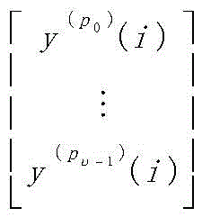
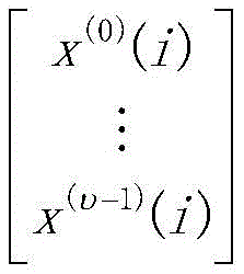
根据如下公式将v个数据层映射到v个DMRS端口上发送给终端:According to the following formula, the v data layers are mapped to the v DMRS ports and sent to the terminal:

其中,


可选地,所述DMRS端口排序规则是采用如下方式之一预设的:Optionally, the DMRS port sorting rule is preset in one of the following ways:
方式1-1:根据DMRS端口向量中包含的DMRS端口编号从小到大的顺序进行排列;Mode 1-1: Arrange according to the order of the DMRS port numbers contained in the DMRS port vector from small to large;
方式1-2:根据DMRS端口向量中包含的DMRS端口所属的CDM组的编号,对CDM组进行排列;例如:Mode 1-2: Arrange the CDM groups according to the numbers of the CDM groups to which the DMRS ports included in the DMRS port vector belong; for example:
包含两个CDM组时,排序可以是0、1或者1、0;When two CDM groups are included, the order can be 0, 1 or 1, 0;
包含三个CDM组时,排序可以是0、1、2或者0、2、1或者1、0、2或者1、2、0或者2、0、1或者2、1、0;When three CDM groups are included, the order can be 0, 1, 2 or 0, 2, 1 or 1, 0, 2 or 1, 2, 0 or 2, 0, 1 or 2, 1, 0;
并且,对每一CDM组,根据DMRS端口编号进行组内的DMRS端口排序;例如,根据DMRS端口编号从小到大的顺序进行排列。In addition, for each CDM group, the DMRS ports in the group are sorted according to the DMRS port numbers; for example, the DMRS ports are sorted according to the descending order of the DMRS port numbers.
方式1-3:Ways 1-3:
单码字传输时,采用上述方式1-1或方式1-2;When a single codeword is transmitted, the above method 1-1 or method 1-2 is used;
双码字传输时,包括下面两个步骤:When the double codeword is transmitted, it includes the following two steps:
第一步、根据配置或指示的DMRS QCL分组参数,在下行控制信息(DCI) 分配的DMRS端口中,对DMRS端口进行分组,针对每一分组DMRS-group:The first step is to group the DMRS ports in the DMRS ports allocated by the downlink control information (DCI) according to the configured or indicated DMRS QCL grouping parameters, and for each grouped DMRS-group:
按照DMRS端口编号从小到大的顺序对DMRS端口进行排序,或者Sort DMRS ports in ascending order of DMRS port number, or
根据组内各DMRS端口所属的CDM组的编号,对CDM组进行排序,在每个CDM组中,根据DMRS端口编号从小到大的顺序进行排序;Sort the CDM groups according to the numbers of the CDM groups to which each DMRS port in the group belongs, and in each CDM group, sort according to the order of the DMRS port numbers from small to large;
第二步、DMRS-group的组间排序:The second step, the inter-group sorting of DMRS-group:
当数据层数为奇数时:When the number of data layers is odd:
将包含DMRS端口数量较少的分组放在靠前的位置,或者Put packets containing fewer DMRS ports first, or
根据DMRS-group的编号,对各DMRS-group进行排序,例如:DMRS-group1,DMRS-group2或者DMRS-group2,DMRS-group1,并将对应的DMRS分组进行排序;Sort each DMRS-group according to the number of the DMRS-group, for example: DMRS-group1, DMRS-group2 or DMRS-group2, DMRS-group1, and sort the corresponding DMRS groups;
本申请实施例中所述的“数据层”,即layer,是指MIMO传输的数据流。The "data layer" in the embodiments of this application, that is, layer, refers to a data stream transmitted by MIMO.
当数据层数为偶数时:When the number of data layers is even:
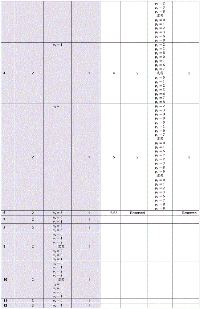
保证码字1对应的DMRS端口集合(对应于一个DMRS-group)与层数-1 时,码字1对应的DMRS端口集合(对应于一个DMRS-group)相同,而码字 0对应的DMRS端口集合(对应于一个DMRS-group)包含了层数-1时码字0 对应的DMRS端口集合(对应于一个DMRS-group),以下面的表case2-2-2为例,双码字且value=2和3时,分别对应rank5和6的情况,如果rank5时,占用的端口为01236,且排序为23016。根据目前的码字到层的映射关系,码字0 映射到端口23,码字1映射到了016。那么在rank6时,应当选择238016的端口排序方式,这样,码字1使用的仍然是端口016,码字0使用的端口集合中多了一个端口8;Ensure that the DMRS port set corresponding to codeword 1 (corresponding to a DMRS-group) is the same as the layer number -1, the DMRS port set corresponding to codeword 1 (corresponding to a DMRS-group) is the same, and the DMRS port corresponding to codeword 0. The set (corresponding to a DMRS-group) contains the DMRS port set (corresponding to a DMRS-group) corresponding to the codeword 0 when the layer number is -1. Take the following table case2-2-2 as an example, the double codeword and value = 2 and 3, corresponding to rank 5 and 6 respectively, if
或者,根据DMRS-group的编号,对各DMRS-group进行排序,例如: DMRS-group1,DMRS-group2或者DMRS-group2,DMRS-group1,并将对应的DMRS分组进行排序;Or, sort each DMRS-group according to the number of the DMRS-group, for example: DMRS-group1, DMRS-group2 or DMRS-group2, DMRS-group1, and sort the corresponding DMRS groups;
方式1-4:Ways 1-4:
当使用一个DMRS-group时,采用上述方式1-1或方式1-2;When using a DMRS-group, use the above method 1-1 or method 1-2;
当使用两个DMRS-group时:When using two DMRS-groups:
根据高层配置的DMRS QCL分组参数,在DCI分配的DMRS端口中,对 DMRS端口进行分组(例如在DCI分配的DMRS端口中,属于DMRS-group1 的分为一组,属于DMRS-group2的分为一组),针对每一分组DMRS-group:按照DMRS端口编号从小到大的顺序对DMRS端口进行排序;或者根据 DMRS-group内各DMRS端口所属的CDM组的编号,对CDM组进行排列,在每个CDM组中,根据DMRS端口编号从小到大的顺序进行排序;According to the DMRS QCL grouping parameters configured by the high layer, in the DMRS ports allocated by the DCI, the DMRS ports are grouped (for example, in the DMRS ports allocated by the DCI, those belonging to DMRS-group1 are grouped into one group, and those belonging to DMRS-group2 are grouped into one group. group), for each grouping DMRS-group: sort the DMRS ports according to the order of the DMRS port numbers from small to large; In each CDM group, sort according to the order of DMRS port numbers from small to large;
将包含DMRS端口数较少的DMRS-group放在靠前位置。Place the DMRS-group with fewer DMRS ports at the front.
需要说明的是,上述各个方式,同样适用于终端侧的方法,即终端侧也可以采用上述各个方式确定DMRS端口排序规则,后续不再赘述。It should be noted that the above manners are also applicable to the methods on the terminal side, that is, the terminal side may also use the above manners to determine the DMRS port ordering rules, which will not be described in detail later.
可选地,该方法还包括:Optionally, the method further includes:
向所述终端发送DCI,用以使得终端根据该DCI确定DMRS端口的配置参数。该DCI中,例如包括当前DMRS高层配置参数,例如DMRS配置类型和DMRS最大符号数(即传输DMRS时使用的最大连续符号数)。其中,所述 DMRS配置类型例如是下行链路的DMRS配置类型(DL-DMRS-config-type),当然,上行链路的也可以。所述DMRS最大符号数例如是下行链路的DMRS 最大符号数(DL-DMRS-max-len),当然,上行链路的也可以。Sending the DCI to the terminal, so that the terminal determines the configuration parameters of the DMRS port according to the DCI. The DCI, for example, includes the current DMRS high-layer configuration parameters, such as the DMRS configuration type and the maximum number of DMRS symbols (ie, the maximum number of consecutive symbols used when transmitting DMRS). Wherein, the DMRS configuration type is, for example, a downlink DMRS configuration type (DL-DMRS-config-type), and of course, an uplink one may also be used. The maximum number of DMRS symbols is, for example, the maximum number of DMRS symbols of the downlink (DL-DMRS-max-len), and of course, the number of uplink DMRS may also be used.
相应地,在终端侧,参见图6,本申请实施例提供的一种数据接收方法,包括:Correspondingly, on the terminal side, referring to FIG. 6 , a data receiving method provided by an embodiment of the present application includes:
S201、确定预先设定的DMRS端口排序规则;S201. Determine a preset DMRS port sorting rule;
S202、根据所述预先设定的DMRS端口排序规则,接收映射到解调参考信号DMRS端口上发送的数据层。S202. According to the preset DMRS port sorting rule, receive the data layer mapped to the demodulation reference signal DMRS port and sent on the DMRS port.
可选地,根据所述预先设定的DMRS端口排序规则,接收映射到解调参考信号DMRS端口上发送的数据层,具体包括:Optionally, according to the preset DMRS port sorting rule, receiving the data layer mapped to the DMRS port sent on the demodulation reference signal, specifically includes:
根据如下公式接收映射到传输时使用的DMRS端口上发送的数据层:Receive the data layer that is mapped to the data layer sent on the DMRS port used for transmission according to the following formula:

其中,


可选地,终端可以根据如下方式之一确定
方式3-1:Way 3-1:
终端根据收取的DCI,确定在当前DMRS高层配置参数DMRS配置类型 (如DL-DMRS-config-type)与下行链路DMRS最大符号数(如 DL-DMRS-max-len)(即传输DMRS时使用的最大连续符号数)条件下,该终端使用的DMRS端口集合;According to the received DCI, the terminal determines the current DMRS high-level configuration parameter DMRS configuration type (such as DL-DMRS-config-type) and the maximum number of downlink DMRS symbols (such as DL-DMRS-max-len) (that is, it is used when transmitting DMRS. The DMRS port set used by the terminal under the condition of the maximum number of consecutive symbols);
终端根据上述使用的DMRS端口集合与

方式3-2:Way 3-2:
终端根据收取的DCI,确定在当前DMRS高层配置参数 DL-DMRS-config-type与DL-DMRS-max-len条件下,码字数、各码字开关状态、以及天线端口指示信息域与

其中,所述天线端口指示信息域,例如下面的case3中所提供的列表中的 value一列,即DCI中用于DMRS端口分配指示的信息域,即case3中的列表的value一列,每一个value取值,对应于码字数及其开关状态、占用CDM组数、使用的front-load DMRS符号数的一种组合状态下,给终端分配的DMRS 端口集合,例如在case3中,经过排序的DMRS端口集合,即P0至Pv-1。The antenna port indication information field, for example, the value column in the list provided in the following case3, that is, the information field used for DMRS port allocation indication in the DCI, that is, the value column of the list in case3, each value takes The value corresponds to the set of DMRS ports allocated to the terminal in a combined state of the number of codewords and their on/off states, the number of occupied CDM groups, and the number of front-load DMRS symbols used. For example, in
下面分三种大的情况case1、case2和case3分别进行说明。The following three major cases, case1, case2 and case3, will be described separately.
case1:case1:
根据高层配置参数DL-DMRS-config-type与DL-DMRS-max-len,分别按照下面的表case1-1-1、case1-1-2、case1-2-1、case1-2-2所示的方式,确定DMRS 端口向量
其中,DMRS端口集合(case1中各表的DMRS port(s)所对应的一列) 通过DCI确定。The DMRS port set (a column corresponding to the DMRS port(s) of each table in case1) is determined by DCI.
如果高层配置的DMRS配置参数为:DL-DMRS-config-type=1且 DL-DMRS-max-len=1,则DMRS端口向量
可选地,当DMRS配置类型为第一类型(例如DL-DMRS-config-type=1),且DMRS最大符号数为1(例如DL-DMRS-max-len=1)时,{P0,…,Pv-1}的取值通过表case1-1-1确定:Optionally, when the DMRS configuration type is the first type (for example, DL-DMRS-config-type=1), and the maximum number of DMRS symbols is 1 (for example, DL-DMRS-max-len=1), {P 0 , ..., the value of P v-1 } is determined by the table case1-1-1:

表case1-1-1Table case1-1-1
其中,DMRS port(s)表示DMRS端口集合,是通过DCI通知给终端的。Wherein, DMRS port(s) represents a set of DMRS ports, which is notified to the terminal through DCI.
表中的0-2表示包括DMRS端口0、DMRS端口1和DMRS端口2。表中的0-3表示包括DMRS端口0、DMRS端口1、DMRS端口2和DMRS端口3。下面的表同理解释,后续不再赘述。0-2 in the table indicates that DMRS port 0,
如果高层配置的DMRS配置参数为:DL-DMRS-config-type=1且 DL-DMRS-max-len=2,则DMRS端口向量
即可选地,当DMRS配置类型为第一类型(例如DL-DMRS-config-type=1),且DMRS最大符号数为2(例如DL-DMRS-max-len=2)时,{P0,…,Pv-1}的取值通过下表case1-1-2确定:Alternatively, when the DMRS configuration type is the first type (eg, DL-DMRS-config-type=1), and the maximum number of DMRS symbols is 2 (eg, DL-DMRS-max-len=2), {P 0 ,...,P v-1 } The value is determined by the following table case1-1-2:


表case1-1-2Table case1-1-2
其中,DMRS port(s)表示DMRS端口集合,是通过DCI通知给终端的。Wherein, DMRS port(s) represents a set of DMRS ports, which is notified to the terminal through DCI.
如果高层配置的DMRS配置参数为:DL-DMRS-config-type=2且 DL-DMRS-max-len=1,则DMRS端口向量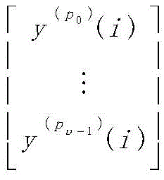
即可选地,当DMRS配置类型为第二类型(例如DL-DMRS-config-type=2),且DMRS最大符号数为1(例如DL-DMRS-max-len=1)时,{P0,…,Pv-1}的取值通过下表case1-2-1确定:Alternatively, when the DMRS configuration type is the second type (eg, DL-DMRS-config-type=2), and the maximum number of DMRS symbols is 1 (eg, DL-DMRS-max-len=1), {P 0 ,...,P v-1 } The value is determined by the following table case1-2-1:


表case1-2-1Table case1-2-1
其中,DMRS port(s)表示DMRS端口集合,是通过DCI通知给终端的。Wherein, DMRS port(s) represents a set of DMRS ports, which is notified to the terminal through DCI.
如果高层配置的DMRS配置参数为:DL-DMRS-config-type=2且 DL-DMRS-max-len=2,则DMRS端口向量
即可选地,当DMRS配置类型为第二类型(例如DL-DMRS-config-type=2),且DMRS最大符号数为2(例如DL-DMRS-max-len=2)时,{P0,…,Pv-1}的取值通过下表case1-2-2确定:Alternatively, when the DMRS configuration type is the second type (eg, DL-DMRS-config-type=2), and the maximum number of DMRS symbols is 2 (eg, DL-DMRS-max-len=2), {P 0 ,...,P v-1 } is determined by the following table case1-2-2:


表case1-2-2Table case1-2-2
其中,DMRS port(s)表示DMRS端口集合,是通过DCI通知给终端的。Wherein, DMRS port(s) represents a set of DMRS ports, which is notified to the terminal through DCI.
case2:case2:
根据高层配置参数DL-DMRS-config-type与DL-DMRS-max-len,分别按照表case2-1-1、case2-1-2、case2-2-1、case2-2-2所示的方式,确定DMRS端口向量
其中,天线端口指示信息域取值、DMRS端口集合(case2中各表的DMRS port(s)所对应的一列)通过DCI确定。The value of the antenna port indication information field and the DMRS port set (a column corresponding to the DMRS port(s) of each table in case 2) are determined by DCI.
如果高层配置的DMRS配置参数为:DL-DMRS-config-type=1且 DL-DMRS-max-len=1,则DMRS端口向量
即可选地,当DMRS配置类型为第一类型,且DMRS最大符号数为1时, {P0,…,Pv-1}的取值通过表case2-1-1确定:That is, when the DMRS configuration type is the first type and the maximum number of DMRS symbols is 1, the value of {P 0 ,...,P v-1 } is determined by the table case2-1-1:

表case2-1-1Table case2-1-1
其中,One Codeword:Codeword 0 enabled,Codeword 1disabled表示一个码字,码字0有效,码字1无效,Value表示DMRS端口指示信息域取值,Number of DMRS CDM group(s) without data表示没有数据的DMRS CDM组的数量, DMRS port(s)表示DMRS端口集合,是通过DCI通知给终端的。Among them, One Codeword: Codeword 0 enabled, Codeword 1disabled indicates a codeword, codeword 0 is valid,
如果高层配置的DMRS配置参数为:DL-DMRS-config-type=1且 DL-DMRS-max-len=2,则DMRS端口向量
即可选地,当DMRS配置类型为第一类型,且DMRS最大符号数为2时, {P0,…,Pv-1}的取值通过表case2-1-2确定:That is, when the DMRS configuration type is the first type and the maximum number of DMRS symbols is 2, the value of {P 0 ,...,P v-1 } is determined by table case2-1-2:


表case2-1-2Table case2-1-2
其中,One Codeword:Codeword 0 enabled,Codeword 1disabled表示一个码字,码字0有效,码字1无效,Two Codewords:Codeword 0 enabled,Codeword 1 enabled表示两个码字,码字0有效,码字1有效,Value表示DMRS端口指示信息域取值,Number of DMRS CDMgroup(s) without data表示没有数据的 DMRS CDM组的数量,Number of front-loadsymbols表示前置的DMRS符号的数量,DMRS port(s)表示DMRS端口集合,是通过DCI通知给终端的。Among them, One Codeword: Codeword 0 enabled,
如果高层配置的DMRS配置参数为:DL-DMRS-config-type=2且 DL-DMRS-max-len=1,则DMRS端口向量
即可选地,当DMRS配置类型为第二类型,且DMRS最大符号数为1时, {P0,…,Pv-1}的取值通过表case2-2-1确定:That is, when the DMRS configuration type is the second type, and the maximum number of DMRS symbols is 1, the value of {P 0 ,...,P v-1 } is determined by the table case2-2-1:


表case2-2-1Table case2-2-1
其中,One Codeword:Codeword 0 enabled,Codeword 1disabled表示一个码字,码字0有效,码字1无效,Two Codewords:Codeword 0 enabled,Codeword 1 enabled表示两个码字,码字0有效,码字1有效,Value表示DMRS端口指示信息域取值,Number of DMRS CDMgroup(s) without data表示没有数据的 DMRS CDM组的数量,Number of front-loadsymbols表示前置的DMRS符号的数量,DMRS port(s)表示DMRS端口集合,是通过DCI通知给终端的。Among them, One Codeword: Codeword 0 enabled,
如果高层配置的DMRS配置参数为:DL-DMRS-config-type=2且DL-DMRS-max-len=2,则DMRS端口向量
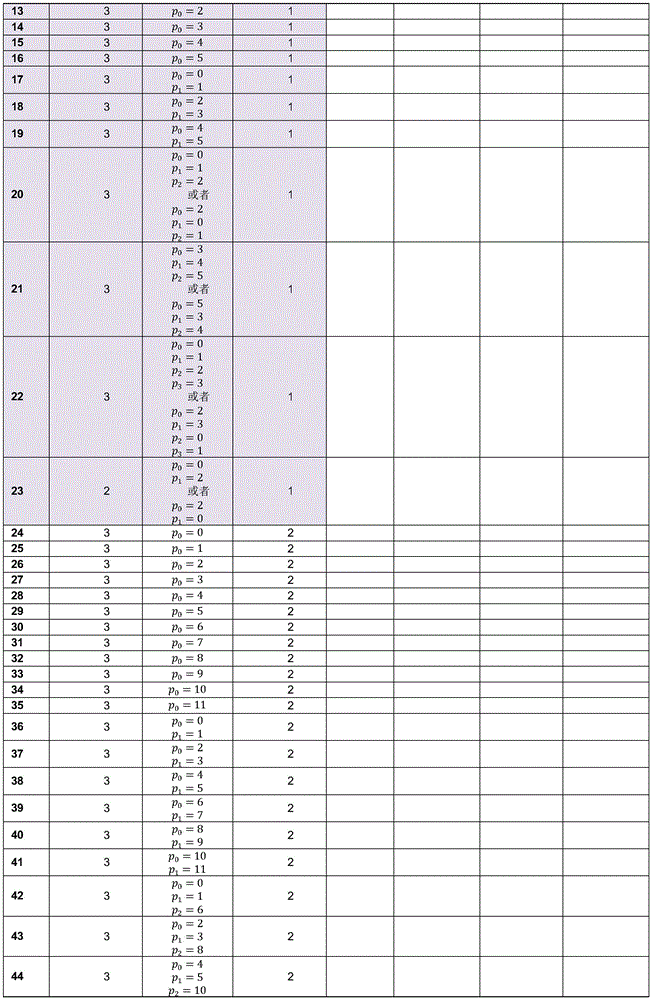
即可选地,当DMRS配置类型为第二类型,且DMRS最大符号数为2时, {P0,…,Pv-1}的取值通过表case2-2-2确定:That is, when the DMRS configuration type is the second type and the maximum number of DMRS symbols is 2, the value of {P 0 ,...,P v-1 } is determined by table case2-2-2:


表case2-2-2Table case2-2-2
其中,One Codeword:Codeword 0 enabled,Codeword 1disabled表示一个码字,码字0有效,码字1无效,Two Codewords:Codeword 0 enabled,Codeword 1 enabled表示两个码字,码字0有效,码字1有效,Value表示DMRS端口指示信息域取值,Number of DMRS CDMgroup(s) without data表示没有数据的 DMRS CDM组的数量,Number of front-loadsymbols表示前置的DMRS符号的数量,DMRS port(s)表示DMRS端口集合,是通过DCI通知给终端的。Among them, One Codeword: Codeword 0 enabled,
case3:case3:
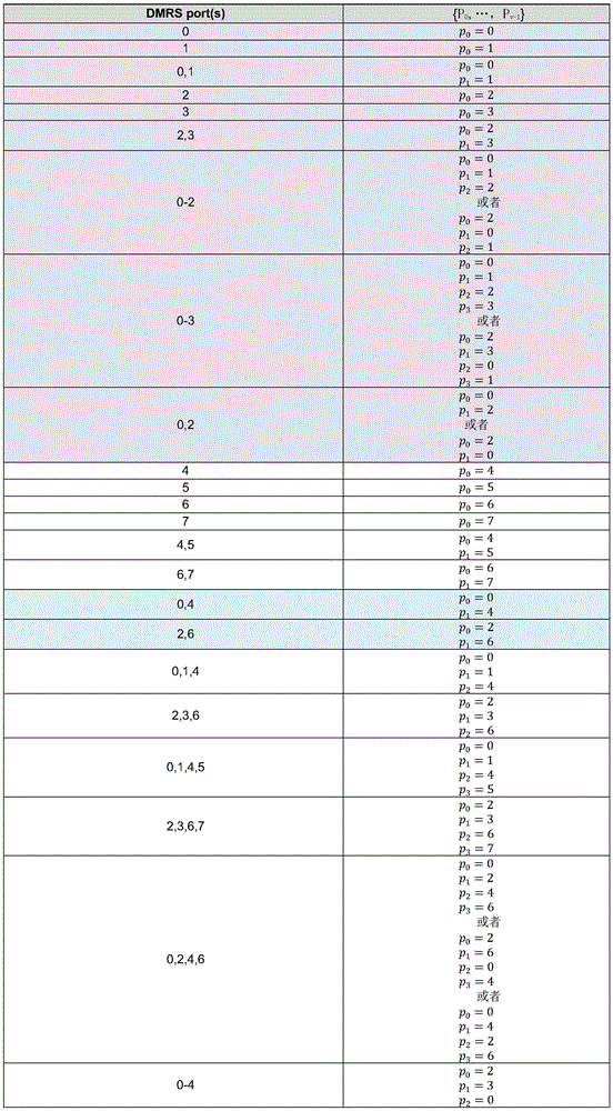
根据高层配置参数DL-DMRS-config-type与DL-DMRS-max-len,分别按照表case3-1-1、case3-1-2、case3-2-1、case3-2-2所示的方式,通过DCI中码字数与各码字开关状态以及天线端口指示信息域(case3中各表的value一列)与 DMRS端口向量

如果高层配置的DMRS配置参数为:DL-DMRS-config-type=1且 DL-DMRS-max-len=1,则DMRS端口向量
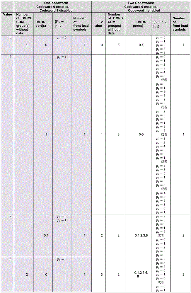
即可选地,当DMRS配置类型为第一类型,且DMRS最大符号数为1时, {P0,…,Pv-1}的取值通过表case3-1-1确定:That is, when the DMRS configuration type is the first type, and the maximum number of DMRS symbols is 1, the value of {P 0 ,...,P v-1 } is determined by table case3-1-1:

表case3-1-1Table case3-1-1
其中,One Codeword:Codeword 0 enabled,Codeword 1disabled表示一个码字,码字0有效,码字1无效;Value表示DMRS端口指示信息域取值;Number of DMRS CDM group(s) without data表示没有数据的DMRS CDM组的数量。Among them, One Codeword: Codeword 0 enabled, Codeword 1disabled indicates a codeword, codeword 0 is valid, and
如果高层配置的DMRS配置参数为:DL-DMRS-config-type=1且DL-DMRS-max-len=2,则DMRS端口向量
即可选地,当DMRS配置类型为第一类型,且DMRS最大符号数为2时, {P0,…,Pv-1}的取值通过表case3-1-2确定:That is, when the DMRS configuration type is the first type, and the maximum number of DMRS symbols is 2, the value of {P 0 ,...,P v-1 } is determined through table case3-1-2:


表case3-1-2Table case3-1-2
其中,One Codeword:Codeword 0 enabled,Codeword 1disabled表示一个码字,码字0有效,码字1无效;Two Codewords:Codeword 0 enabled,Codeword 1 enabled表示两个码字,码字0有效,码字1有效;Value表示DMRS端口指示信息域取值;Number of DMRS CDMgroup(s) without data表示没有数据的 DMRS CDM组的数量;Number of front-loadsymbols表示前置的DMRS符号的数量。Among them, One Codeword: Codeword 0 enabled,
如果高层配置的DMRS配置参数为:DL-DMRS-config-type=2且 DL-DMRS-max-len=1,则DMRS端口向量
即可选地,当DMRS配置类型为第二类型,且DMRS最大符号数为1时, {P0,…,Pv-1}的取值通过表case3-2-1确定:That is, when the DMRS configuration type is the second type, and the maximum number of DMRS symbols is 1, the value of {P 0 ,...,P v-1 } is determined through table case3-2-1:


表case3-2-1Table case3-2-1
其中,One Codeword:Codeword 0 enabled,Codeword 1disabled表示一个码字,码字0有效,码字1无效;Two Codewords:Codeword 0 enabled,Codeword 1 enabled表示两个码字,码字0有效,码字1有效;Value表示DMRS端口指示信息域取值;Number of DMRS CDMgroup(s) without data表示没有数据的 DMRS CDM组的数量。Among them, One Codeword: Codeword 0 enabled,
如果高层配置的DMRS配置参数为:DL-DMRS-config-type=2且DL-DMRS-max-len=2,则DMRS端口向量
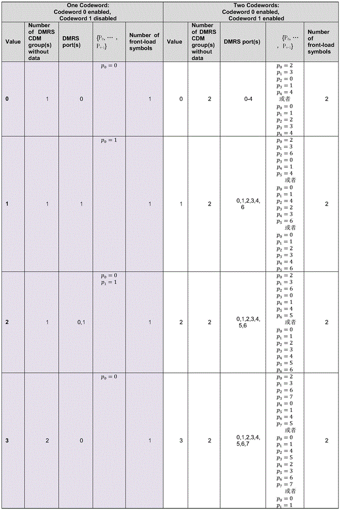
即可选地,当DMRS配置类型为第二类型,且DMRS最大符号数为2时, {P0,…,Pv-1}的取值通过表case3-2-2确定:That is, when the DMRS configuration type is the second type and the maximum number of DMRS symbols is 2, the value of {P 0 ,...,P v-1 } is determined by table case3-2-2:


表case3-2-2Table case3-2-2
其中,One Codeword:Codeword 0 enabled,Codeword 1disabled表示一个码字,码字0有效,码字1无效;Two Codewords:Codeword 0 enabled,Codeword 1 enabled表示两个码字,码字0有效,码字1有效;Value表示DMRS端口指示信息域取值;Number of DMRS CDMgroup(s) without data表示没有数据的 DMRS CDM组的数量;Number of front-loadsymbols表示前置的DMRS符号的数量。Among them, One Codeword: Codeword 0 enabled,
在网络侧,参见图7,本申请实施例提供的一种数据发送装置,包括:存储器520和处理器500,其中,所述存储器用于存储程序指令,所述处理器用于调用所述存储器中存储的程序指令,按照获得的程序执行:On the network side, referring to FIG. 7 , a data sending apparatus provided by an embodiment of the present application includes: a
确定预先设定的解调参考信号DMRS端口排序规则;Determine a preset demodulation reference signal DMRS port ordering rule;
根据所述预先设定的DMRS端口排序规则,将数据层映射到传输时使用的DMRS端口上通过收发机510发送给终端。According to the preset DMRS port ordering rule, the data layer is mapped to the DMRS port used for transmission and sent to the terminal through the
其中,需要说明的是,图7中的总线接口、收发机510等都可以作为可选器件存在于本申请实施例提供的一种数据发送装置中,不是必需的。It should be noted that, the bus interface, the
可选地,所述DMRS端口排序规则是采用如下方式之一预设的:Optionally, the DMRS port sorting rule is preset in one of the following ways:
方式1-1:根据DMRS端口向量中包含的DMRS端口编号从小到大的顺序进行排列;Mode 1-1: Arrange according to the order of the DMRS port numbers contained in the DMRS port vector from small to large;
方式1-2:根据DMRS端口向量中包含的DMRS端口所属的CDM组的编号,对CDM组进行排列,并且对每一CDM组,根据DMRS端口编号进行组内的DMRS端口排序;Mode 1-2: According to the number of the CDM group to which the DMRS port included in the DMRS port vector belongs, the CDM groups are arranged, and for each CDM group, the DMRS ports in the group are sorted according to the DMRS port number;
方式1-3:Ways 1-3:
单码字传输时,采用上述方式1-1或方式1-2;When a single codeword is transmitted, the above method 1-1 or method 1-2 is used;
双码字传输时:When two codewords are transmitted:
根据配置或指示的DMRS QCL分组参数,在DCI分配的DMRS端口中,对DMRS端口进行分组,针对每一分组DMRS-group:According to the configured or indicated DMRS QCL grouping parameters, among the DMRS ports allocated by the DCI, the DMRS ports are grouped, and for each group DMRS-group:
按照DMRS端口编号从小到大的顺序对DMRS端口进行排序,或者Sort DMRS ports in ascending order of DMRS port number, or
根据组内各DMRS端口所属的CDM组的编号,对CDM组进行排序,在每个CDM组中,根据DMRS端口编号从小到大的顺序进行排序;Sort CDM groups according to the number of the CDM group to which each DMRS port in the group belongs, and in each CDM group, sort according to the order of the DMRS port numbers from small to large;
当数据层数为奇数时:When the number of data layers is odd:
将包含DMRS端口数量较少的分组放在靠前的位置,或者Put packets containing fewer DMRS ports first, or
根据DMRS-group的编号,对各DMRS-group进行排序;Sort each DMRS-group according to the number of the DMRS-group;
当数据层数为偶数时:When the number of data layers is even:
保证码字1对应的DMRS端口集合与层数-1时,码字1对应的DMRS端口集合相同,而码字0对应的DMRS端口集合包含了层数-1时码字0对应的 DMRS端口集合,或者;When the DMRS port set corresponding to
根据DMRS-group的编号,对各DMRS-group进行排序;Sort each DMRS-group according to the number of the DMRS-group;
方式1-4:Ways 1-4:
当使用一个DMRS-group时,采用上述方式1-1或方式1-2;When using a DMRS-group, use the above method 1-1 or method 1-2;
当使用两个DMRS-group时:When using two DMRS-groups:
根据高层配置的DMRS QCL分组参数,在DCI分配的DMRS端口中,对 DMRS端口进行分组,针对每一分组DMRS-group:According to the DMRS QCL grouping parameters configured by the high layer, in the DMRS ports allocated by the DCI, the DMRS ports are grouped, and for each grouping DMRS-group:
按照DMRS端口编号从小到大的顺序对DMRS端口进行排序,或者Sort DMRS ports in ascending order of DMRS port number, or
根据DMRS-group内各DMRS端口所属的CDM组的编号,对CDM组进行排列,在每个CDM组中,根据DMRS端口编号从小到大的顺序进行排序;According to the number of the CDM group to which each DMRS port in the DMRS-group belongs, the CDM groups are arranged, and in each CDM group, the order of the DMRS port numbers from small to large is sorted;
将包含DMRS端口数较少的DMRS-group放在靠前位置。Place the DMRS-group with fewer DMRS ports at the front.
可选地,所述处理器还用于:通过收发机向所述终端发送DCI,用以使得终端根据该DCI确定DMRS端口的配置参数。Optionally, the processor is further configured to: send the DCI to the terminal through the transceiver, so that the terminal determines the configuration parameter of the DMRS port according to the DCI.
收发机510,用于在处理器500的控制下接收和发送数据。The
其中,在图7中,总线架构可以包括任意数量的互联的总线和桥,具体由处理器500代表的一个或多个处理器和存储器520代表的存储器的各种电路链接在一起。总线架构还可以将诸如外围设备、稳压器和功率管理电路等之类的各种其他电路链接在一起,这些都是本领域所公知的,因此,本文不再对其进行进一步描述。总线接口提供接口。收发机510可以是多个元件,即包括发送机和收发机,提供用于在传输介质上与各种其他装置通信的单元。处理器500 负责管理总线架构和通常的处理,存储器520可以存储处理器500在执行操作时所使用的数据。7, the bus architecture may include any number of interconnected buses and bridges, specifically one or more processors represented by
处理器500可以是中央处埋器(CPU)、专用集成电路(Application SpecificIntegrated Circuit,ASIC)、现场可编程门阵列(Field-Programmable Gate Array,FPGA)或复杂可编程逻辑器件(Complex Programmable Logic Device,CPLD)。The
参见图8,在终端侧,本申请实施例提供的一种信息确定装置,包括:存储器620和处理器600,其中,所述存储器用于存储程序指令,所述处理器用于调用所述存储器中存储的程序指令,按照获得的程序执行:Referring to FIG. 8 , on the terminal side, an apparatus for determining information provided by an embodiment of the present application includes: a
确定预先设定的DMRS端口排序规则;Determine the preset DMRS port ordering rules;
根据所述预先设定的DMRS端口排序规则,通过收发机610接收映射到解调参考信号DMRS端口上发送的数据层。According to the preset DMRS port ordering rule, the
需要说明的是,图8中除了存储器620和处理器600之外的器件都是可选器件存在于本申请实施例提供的一种数据接收装置中,不作为必选器件。It should be noted that, the devices other than the
本申请实施例中提供的终端侧的装置中的处理器600,可以执行上述终端侧的数据接收方法所述的任何步骤,在此不再赘述。The
收发机610,用于在处理器600的控制下接收和发送数据。The
其中,在图8中,总线架构可以包括任意数量的互联的总线和桥,具体由处理器600代表的一个或多个处理器和存储器620代表的存储器的各种电路链接在一起。总线架构还可以将诸如外围设备、稳压器和功率管理电路等之类的各种其他电路链接在一起,这些都是本领域所公知的,因此,本文不再对其进行进一步描述。总线接口提供接口。收发机610可以是多个元件,即包括发送机和接收机,提供用于在传输介质上与各种其他装置通信的单元。针对不同的用户设备,用户接口630还可以是能够外接内接需要设备的接口,连接的设备包括但不限于小键盘、显示器、扬声器、麦克风、操纵杆等。8, the bus architecture may include any number of interconnected buses and bridges, specifically one or more processors represented by
处理器600负责管理总线架构和通常的处理,存储器620可以存储处理器 600在执行操作时所使用的数据。The
可选的,处理器600可以是CPU(中央处埋器)、ASIC(Application SpecificIntegrated Circuit,专用集成电路)、FPGA(Field-Programmable Gate Array,现场可编程门阵列)或CPLD(Complex Programmable Logic Device,复杂可编程逻辑器件)。Optionally, the
在网络侧,参见图9,本申请实施例提供的另一种数据发送装置,包括:On the network side, referring to FIG. 9 , another data sending apparatus provided by an embodiment of the present application includes:
确定单元11,用于确定预先设定的解调参考信号DMRS端口排序规则;A
指示单元12,用于根据所述预先设定的DMRS端口排序规则,将数据层映射到传输时使用的DMRS端口上发送给终端。The instructing
在终端侧,参见图10,本申请实施例提供的另一种信息确定装置,包括:On the terminal side, referring to FIG. 10 , another information determination apparatus provided by this embodiment of the present application includes:
接收单元21,用于确定预先设定的DMRS端口排序规则;a receiving
确定单元22,用于根据所述预先设定的DMRS端口排序规则,接收映射到解调参考信号DMRS端口上发送的数据层。The determining
本申请实施例提供了一种计算机存储介质,用于储存为上述计算设备所用的计算机程序指令,其包含用于执行上述信息指示或确定方法的程序。An embodiment of the present application provides a computer storage medium for storing computer program instructions used by the above-mentioned computing device, which includes a program for executing the above-mentioned information indication or determination method.
所述计算机存储介质可以是计算机能够存取的任何可用介质或数据存储设备,包括但不限于磁性存储器(例如软盘、硬盘、磁带、磁光盘(MO)等)、光学存储器(例如CD、DVD、BD、HVD等)、以及半导体存储器(例如ROM、 EPROM、EEPROM、非易失性存储器(NAND FLASH)、固态硬盘(SSD)) 等。The computer storage medium can be any available medium or data storage device that can be accessed by a computer, including, but not limited to, magnetic storage (eg, floppy disk, hard disk, magnetic tape, magneto-optical disk (MO), etc.), optical storage (eg, CD, DVD, BD, HVD, etc.), and semiconductor memory (eg, ROM, EPROM, EEPROM, non-volatile memory (NAND FLASH), solid-state disk (SSD)), and the like.
本申请实施例提供的方法可以应用于终端设备,也可以应用于网络设备。The methods provided in the embodiments of the present application may be applied to terminal devices, and may also be applied to network devices.
其中,终端设备也可称之为用户设备(User Equipment,简称为“UE”)、移动台(Mobile Station,简称为“MS”)、移动终端(Mobile Terminal)等,可选的,该终端可以具备经无线接入网(Radio Access Network,RAN)与一个或多个核心网进行通信的能力,例如,终端可以是移动电话(或称为“蜂窝”电话)、或具有移动性质的计算机等,例如,终端还可以是便携式、袖珍式、手持式、计算机内置的或者车载的移动装置。The terminal equipment may also be referred to as user equipment (User Equipment, referred to as "UE"), mobile station (Mobile Station, referred to as "MS"), mobile terminal (Mobile Terminal), etc. Optionally, the terminal may be Have the ability to communicate with one or more core networks via a Radio Access Network (RAN), for example, the terminal may be a mobile phone (or a "cellular" phone), or a computer with a mobile nature, etc., For example, the terminal may also be a portable, pocket-sized, hand-held, computer-built, or vehicle-mounted mobile device.
网络设备可以为基站(例如,接入点),指接入网中在空中接口上通过一个或多个扇区与无线终端通信的设备。基站可用于将收到的空中帧与IP分组进行相互转换,作为无线终端与接入网的其余部分之间的路由器,其中接入网的其余部分可包括网际协议(IP)网络。基站还可协调对空中接口的属性管理。例如,基站可以是GSM或CDMA中的基站(BTS,BaseTransceiver Station),也可以是WCDMA中的基站(NodeB),还可以是LTE中的演进型基站(NodeB 或eNB或e-NodeB,evolutional Node B),本方面实施例中不做限定。本领域内的技术人员应明白,本申请的实施例可提供为方法、系统、或计算机程序产品。因此,本申请可采用完全硬件实施例、完全软件实施例、或结合软件和硬件方面的实施例的形式。而且,本申请可采用在一个或多个其中包含有计算机可用程序代码的计算机可用存储介质(包括但不限于磁盘存储器和光学存储器等)上实施的计算机程序产品的形式。A network device, which may be a base station (eg, an access point), refers to a device in an access network that communicates with wireless terminals over the air interface through one or more sectors. The base station may be used to convert received air frames to and from IP packets, acting as a router between the wireless terminal and the rest of the access network, which may include an Internet Protocol (IP) network. The base station may also coordinate attribute management of the air interface. For example, the base station may be a base station (BTS, BaseTransceiver Station) in GSM or CDMA, a base station (NodeB) in WCDMA, or an evolved base station (NodeB or eNB or e-NodeB, evolutional Node B) in LTE. ), which is not limited in the embodiments of this aspect. As will be appreciated by those skilled in the art, the embodiments of the present application may be provided as a method, a system, or a computer program product. Accordingly, the present application may take the form of an entirely hardware embodiment, an entirely software embodiment, or an embodiment combining software and hardware aspects. Furthermore, the present application may take the form of a computer program product embodied on one or more computer-usable storage media having computer-usable program code embodied therein, including but not limited to disk storage, optical storage, and the like.
本申请是参照根据本申请实施例的方法、设备(系统)、和计算机程序产品的流程图和/或方框图来描述的。应理解可由计算机程序指令实现流程图和 /或方框图中的每一流程和/或方框、以及流程图和/或方框图中的流程和/ 或方框的结合。可提供这些计算机程序指令到通用计算机、专用计算机、嵌入式处理机或其他可编程数据处理设备的处理器以产生一个机器,使得通过计算机或其他可编程数据处理设备的处理器执行的指令产生用于实现在流程图一个流程或多个流程和/或方框图一个方框或多个方框中指定的功能的装置。The present application is described with reference to flowchart illustrations and/or block diagrams of methods, apparatus (systems), and computer program products according to embodiments of the present application. It will be understood that each flow and/or block in the flowchart illustrations and/or block diagrams, and combinations of flows and/or blocks in the flowchart illustrations and/or block diagrams, can be implemented by computer program instructions. These computer program instructions may be provided to the processor of a general purpose computer, special purpose computer, embedded processor or other programmable data processing device to produce a machine such that the instructions executed by the processor of the computer or other programmable data processing device produce Means for implementing the functions specified in a flow or flow of a flowchart and/or a block or blocks of a block diagram.
这些计算机程序指令也可存储在能引导计算机或其他可编程数据处理设备以特定方式工作的计算机可读存储器中,使得存储在该计算机可读存储器中的指令产生包括指令装置的制造品,该指令装置实现在流程图一个流程或多个流程和/或方框图一个方框或多个方框中指定的功能。These computer program instructions may also be stored in a computer readable memory capable of directing a computer or other programmable data processing apparatus to function in a particular manner, such that the instructions stored in the computer readable memory result in an article of manufacture comprising instruction means, the instructions The apparatus implements the functions specified in the flow or flow of the flowcharts and/or the block or blocks of the block diagrams.
这些计算机程序指令也可装载到计算机或其他可编程数据处理设备上,使得在计算机或其他可编程设备上执行一系列操作步骤以产生计算机实现的处理,从而在计算机或其他可编程设备上执行的指令提供用于实现在流程图一个流程或多个流程和/或方框图一个方框或多个方框中指定的功能的步骤。These computer program instructions can also be loaded on a computer or other programmable data processing apparatus to cause a series of operational steps to be performed on the computer or other programmable apparatus to produce a computer-implemented process such that The instructions provide steps for implementing the functions specified in the flow or blocks of the flowcharts and/or the block or blocks of the block diagrams.
显然,本领域的技术人员可以对本申请进行各种改动和变型而不脱离本申请的精神和范围。这样,倘若本申请的这些修改和变型属于本申请权利要求及其等同技术的范围之内,则本申请也意图包含这些改动和变型在内。Obviously, those skilled in the art can make various changes and modifications to the present application without departing from the spirit and scope of the present application. Thus, if these modifications and variations of the present application fall within the scope of the claims of the present application and their equivalents, the present application is also intended to include these modifications and variations.
Claims (35)


Priority Applications (7)
| Application Number | Priority Date | Filing Date | Title |
|---|---|---|---|
| CN201810032484.6A CN110034890B (en) | 2018-01-12 | 2018-01-12 | Data transmission method and device and computer storage medium |
| US16/961,687 US11405157B2 (en) | 2018-01-12 | 2018-12-12 | Data transmission method and apparatus and computer storage medium |
| JP2020538845A JP2021510284A (en) | 2018-01-12 | 2018-12-12 | Methods and devices for transmitting data and computer storage media |
| PCT/CN2018/120742 WO2019137144A1 (en) | 2018-01-12 | 2018-12-12 | Data transmission method and apparatus and computer storage medium |
| KR1020207023215A KR102454234B1 (en) | 2018-01-12 | 2018-12-12 | Methods, devices and computer storage media for transferring data |
| EP18900482.3A EP3739792B1 (en) | 2018-01-12 | 2018-12-12 | Data transmission method and apparatus and computer storage medium |
| TW107146910A TWI744585B (en) | 2018-01-12 | 2018-12-25 | Data transmission method and device, computer storage medium |
Applications Claiming Priority (1)
| Application Number | Priority Date | Filing Date | Title |
|---|---|---|---|
| CN201810032484.6A CN110034890B (en) | 2018-01-12 | 2018-01-12 | Data transmission method and device and computer storage medium |
Publications (2)
| Publication Number | Publication Date |
|---|---|
| CN110034890A CN110034890A (en) | 2019-07-19 |
| CN110034890B true CN110034890B (en) | 2020-07-10 |
Family
ID=67218468
Family Applications (1)
| Application Number | Title | Priority Date | Filing Date |
|---|---|---|---|
| CN201810032484.6A Active CN110034890B (en) | 2018-01-12 | 2018-01-12 | Data transmission method and device and computer storage medium |
Country Status (7)
| Country | Link |
|---|---|
| US (1) | US11405157B2 (en) |
| EP (1) | EP3739792B1 (en) |
| JP (1) | JP2021510284A (en) |
| KR (1) | KR102454234B1 (en) |
| CN (1) | CN110034890B (en) |
| TW (1) | TWI744585B (en) |
| WO (1) | WO2019137144A1 (en) |
Families Citing this family (3)
| Publication number | Priority date | Publication date | Assignee | Title |
|---|---|---|---|---|
| CN114826527A (en) | 2019-07-30 | 2022-07-29 | 华为技术有限公司 | DMRS port indication method and device |
| CN114513236B (en) * | 2020-11-16 | 2023-10-27 | 中国移动通信有限公司研究院 | Multi-antenna precoding method, device and equipment |
| CN118679817A (en) * | 2022-01-28 | 2024-09-20 | 中兴通讯股份有限公司 | Systems and methods for reference signaling for wireless communications |
Citations (1)
| Publication number | Priority date | Publication date | Assignee | Title |
|---|---|---|---|---|
| CN102088429A (en) * | 2010-02-11 | 2011-06-08 | 大唐移动通信设备有限公司 | A method and device for demodulation reference symbol port mapping |
Family Cites Families (15)
| Publication number | Priority date | Publication date | Assignee | Title |
|---|---|---|---|---|
| CN101605375B (en) | 2008-06-11 | 2011-02-09 | 大唐移动通信设备有限公司 | Method for sending signalings on downlink control channel |
| MA33907B1 (en) * | 2010-01-20 | 2013-01-02 | Ericsson Telefon Ab L M | The process of setting the antenna port and the TV receiver signal |
| US9130719B2 (en) | 2010-02-11 | 2015-09-08 | Samsung Electronics Co., Ltd | Method for indicating a DM-RS antenna port in a wireless communication system |
| CN102158319B (en) * | 2010-02-12 | 2015-12-16 | 中兴通讯股份有限公司 | A kind of method for precoding based on hybrid multiplex demodulation reference mark and device |
| CN102299769B (en) * | 2011-09-01 | 2014-06-25 | 电信科学技术研究院 | Downlink control information transmission method and device |
| CN104185960B (en) * | 2011-11-16 | 2018-03-20 | 三星电子株式会社 | Method and device for sending control information in wireless communication system |
| CN103916349B (en) | 2012-12-31 | 2018-03-23 | 中国移动通信集团公司 | Strengthen the collocation method and device of the demodulation reference mark of public search space |
| WO2016099057A1 (en) * | 2014-12-16 | 2016-06-23 | 엘지전자 주식회사 | Method and mtc device for transmitting dmrs for uplink data demodulation |
| JP6027637B2 (en) * | 2015-01-22 | 2016-11-16 | テレフオンアクチーボラゲット エルエム エリクソン(パブル) | Antenna port mapping method and apparatus for demodulated reference signal |
| CN106162890B (en) * | 2015-04-14 | 2020-02-18 | 中国移动通信集团公司 | A kind of indication method, apparatus and base station of demodulation reference signal DMRS port |
| CN107306177B (en) * | 2016-04-22 | 2023-11-10 | 华为技术有限公司 | Methods of transmitting data, user equipment and network side equipment |
| US20180026764A1 (en) * | 2016-07-25 | 2018-01-25 | Qualcomm Incorporated | Method of mapping transmission layers to frequency division multiplexed demodulation reference signal ports |
| GB201809007D0 (en) | 2018-06-01 | 2018-07-18 | Smith & Nephew | Restriction of sensor-monitored region for sensor-enabled wound dressings |
| CN109391413B (en) * | 2017-08-10 | 2022-05-10 | 华为技术有限公司 | Method and communication device for information transmission |
| CN109842468B (en) * | 2017-11-24 | 2020-09-01 | 电信科学技术研究院 | Data transmission method and device and computer storage medium |
-
2018
- 2018-01-12 CN CN201810032484.6A patent/CN110034890B/en active Active
- 2018-12-12 WO PCT/CN2018/120742 patent/WO2019137144A1/en not_active Ceased
- 2018-12-12 KR KR1020207023215A patent/KR102454234B1/en active Active
- 2018-12-12 US US16/961,687 patent/US11405157B2/en active Active
- 2018-12-12 EP EP18900482.3A patent/EP3739792B1/en active Active
- 2018-12-12 JP JP2020538845A patent/JP2021510284A/en active Pending
- 2018-12-25 TW TW107146910A patent/TWI744585B/en active
Patent Citations (1)
| Publication number | Priority date | Publication date | Assignee | Title |
|---|---|---|---|---|
| CN102088429A (en) * | 2010-02-11 | 2011-06-08 | 大唐移动通信设备有限公司 | A method and device for demodulation reference symbol port mapping |
Also Published As
| Publication number | Publication date |
|---|---|
| KR20200108045A (en) | 2020-09-16 |
| CN110034890A (en) | 2019-07-19 |
| EP3739792A4 (en) | 2021-03-03 |
| TWI744585B (en) | 2021-11-01 |
| EP3739792B1 (en) | 2024-02-07 |
| KR102454234B1 (en) | 2022-10-14 |
| WO2019137144A1 (en) | 2019-07-18 |
| JP2021510284A (en) | 2021-04-15 |
| US20210083826A1 (en) | 2021-03-18 |
| TW201931809A (en) | 2019-08-01 |
| US11405157B2 (en) | 2022-08-02 |
| EP3739792A1 (en) | 2020-11-18 |
Similar Documents
| Publication | Publication Date | Title |
|---|---|---|
| CN109842468B (en) | Data transmission method and device and computer storage medium | |
| CN108111272A (en) | Indication method, base station and terminal of reference signal configuration information | |
| CN109802807B (en) | Information indication, resource determination method and device, and computer storage medium | |
| CN108809572A (en) | Communication method and communication device | |
| CN108886394B (en) | Method and device for indicating antenna port | |
| JP2022549946A (en) | Demodulation reference signal configuration information acquisition method, configuration method, and device | |
| JP7267288B2 (en) | Methods and apparatus and computer readable storage media for directing and determining information | |
| CN110034890B (en) | Data transmission method and device and computer storage medium | |
| CN109842469B (en) | Information indication, determination method and device, computer storage medium | |
| JP6739765B2 (en) | CSI-RS transmission method and network device | |
| CN108616340B (en) | A method and apparatus for transmitting pilot signal | |
| CN110138527A (en) | Resource indicating and determining method and device |
Legal Events
| Date | Code | Title | Description |
|---|---|---|---|
| PB01 | Publication | ||
| PB01 | Publication | ||
| SE01 | Entry into force of request for substantive examination | ||
| SE01 | Entry into force of request for substantive examination | ||
| GR01 | Patent grant | ||
| GR01 | Patent grant | ||
| TR01 | Transfer of patent right |
Effective date of registration: 20210525 Address after: 100085 1st floor, building 1, yard 5, Shangdi East Road, Haidian District, Beijing Patentee after: DATANG MOBILE COMMUNICATIONS EQUIPMENT Co.,Ltd. Address before: 100191 No. 40, Haidian District, Beijing, Xueyuan Road Patentee before: Telecommunications Science and Technology Research Institute Co.,Ltd. |
|
| TR01 | Transfer of patent right |