CN110021031B - X-ray image enhancement method based on image pyramid - Google Patents
X-ray image enhancement method based on image pyramid Download PDFInfo
- Publication number
- CN110021031B CN110021031B CN201910247876.9A CN201910247876A CN110021031B CN 110021031 B CN110021031 B CN 110021031B CN 201910247876 A CN201910247876 A CN 201910247876A CN 110021031 B CN110021031 B CN 110021031B
- Authority
- CN
- China
- Prior art keywords
- image
- pyramid
- layer
- max
- formula
- Prior art date
- Legal status (The legal status is an assumption and is not a legal conclusion. Google has not performed a legal analysis and makes no representation as to the accuracy of the status listed.)
- Active
Links
Images


Classifications
-
- G—PHYSICS
- G06—COMPUTING OR CALCULATING; COUNTING
- G06T—IMAGE DATA PROCESSING OR GENERATION, IN GENERAL
- G06T5/00—Image enhancement or restoration
- G06T5/73—Deblurring; Sharpening
-
- G—PHYSICS
- G06—COMPUTING OR CALCULATING; COUNTING
- G06T—IMAGE DATA PROCESSING OR GENERATION, IN GENERAL
- G06T7/00—Image analysis
- G06T7/10—Segmentation; Edge detection
- G06T7/136—Segmentation; Edge detection involving thresholding
-
- G—PHYSICS
- G06—COMPUTING OR CALCULATING; COUNTING
- G06T—IMAGE DATA PROCESSING OR GENERATION, IN GENERAL
- G06T7/00—Image analysis
- G06T7/10—Segmentation; Edge detection
- G06T7/194—Segmentation; Edge detection involving foreground-background segmentation
-
- G—PHYSICS
- G06—COMPUTING OR CALCULATING; COUNTING
- G06T—IMAGE DATA PROCESSING OR GENERATION, IN GENERAL
- G06T2207/00—Indexing scheme for image analysis or image enhancement
- G06T2207/10—Image acquisition modality
- G06T2207/10116—X-ray image
-
- G—PHYSICS
- G06—COMPUTING OR CALCULATING; COUNTING
- G06T—IMAGE DATA PROCESSING OR GENERATION, IN GENERAL
- G06T2207/00—Indexing scheme for image analysis or image enhancement
- G06T2207/20—Special algorithmic details
- G06T2207/20016—Hierarchical, coarse-to-fine, multiscale or multiresolution image processing; Pyramid transform
-
- G—PHYSICS
- G06—COMPUTING OR CALCULATING; COUNTING
- G06T—IMAGE DATA PROCESSING OR GENERATION, IN GENERAL
- G06T2207/00—Indexing scheme for image analysis or image enhancement
- G06T2207/20—Special algorithmic details
- G06T2207/20212—Image combination
- G06T2207/20221—Image fusion; Image merging
Landscapes
- Engineering & Computer Science (AREA)
- Physics & Mathematics (AREA)
- General Physics & Mathematics (AREA)
- Theoretical Computer Science (AREA)
- Computer Vision & Pattern Recognition (AREA)
- Image Processing (AREA)
Abstract
The invention discloses an X-ray image enhancement method based on an image pyramid. The invention has the advantages that: on the premise of ensuring that the background of the X-ray image is not changed, the contrast of a black area with small image gray value difference can be obviously improved, so that the outline of an object in the image is clear and visible.
Description
Technical Field
The invention relates to an image processing technology in the radiation imaging field, in particular to an image processing method for contrast enhancement of a darker area in a radiation image.
Background
Radiation imaging uses a radioscopic scanning imaging technique to generate a gray-scale image, i.e., an X-ray image, of an object to be scanned. The data type of the X-ray image pixels is typically an integer of 12 or 16 bits. The radiation imaging technology is widely applied to the fields of customs vehicle safety inspection, medical diagnosis and the like. According to the imaging principle, the ray absorption rate of the object increases exponentially with the increase of the thickness and the density of the object, so that the thicker or denser object has smaller corresponding gray value in the image, and the difference of the areas with lower gray value is less obvious. The inner contour of the darker area (lower gray value) in the X-ray image is hardly recognized by the naked eye normally. In the security inspection of border vehicles such as customs, the dark area of the image is the key inspection area of the examiner, so that the inner contour of the image needs to be clearly visible by using a computer image enhancement technology.
The image enhancement technology is to improve the quality of the image and the contrast of the image, so that the original unclear image details can be clearly presented, and the interpretability of the image is improved. Common image enhancement methods include edge enhancement, logarithmic transformation, laplacian sharpening, histogram equalization, and the like. The method performs global mathematical operation aiming at the spatial domain of the image, namely, each pixel in the image is subjected to the same mathematical transformation once, the original pixel value is changed, and the aims of improving the image contrast and improving the image quality are fulfilled. Although the contrast of the image can be improved to a certain extent by the conventional method, the improvement of the contrast of a darker area with very small difference of original gray values in the radiation imaging image is limited, and the purpose of clearly displaying the outline inside the dark area cannot be achieved.
Disclosure of Invention
The invention aims to provide an X-ray image enhancement method based on an image pyramid, which is used for enhancing an X-ray image based on the image pyramid, and comprises the steps of carrying out hierarchical decomposition on an input X-ray image with different resolutions, carrying out targeted enhancement processing on each layer of detail images obtained by decomposition, finally carrying out reconstruction fusion on all the enhanced layers of images, and finally outputting an enhanced image with the same resolution, so that the detail outline with small original pixel value difference in the image is clear and visible.
The technical scheme of the invention is as follows:
an X-ray image enhancement method based on an image pyramid comprises the following steps:
in the X-ray image, an object to be scanned is imaged and called a target, and a region other than the target object is called a background. Since the X-ray in the background is not absorbed by any object, the gray value of its pixel is large, appearing as a white area. The target image segmentation sets the pixel value of the background area to 0, and the pixel value of the target object is kept unchanged. In the background image segmentation, the pixel value of a background area is kept unchanged, and the pixel value of a target object is set to be 0. The subsequent image enhancement processing of the method is only carried out on the target image.
Step 1.1: a division threshold thr is set.
thr=c*Max。
Wherein the value range of the coefficient c is c from 0.85 to 0.95, and Max is the maximum value of the original image src.
Step 1.2: and newly creating a flag image flag which is consistent with the original image size and data type, wherein all data positions of all pixel values in the image are set to be 1.
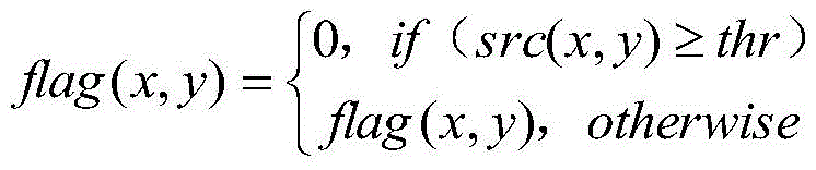
Step 1.3: and generating a final marker map flag according to the threshold thr. And setting the value of each pixel of the generated final flag map flag as flag (x, y), and setting the value of each pixel of the original image src as src (x, y), wherein the operation formula is as follows:
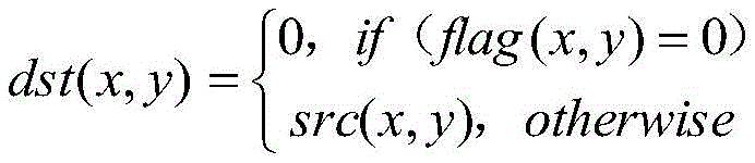
step 1.4: obtaining a target image dst and a background image bak according to the flag obtained in the step 1.3, wherein the target image dst is obtained by adopting a formula:

the background image bak is obtained by adopting a formula:

step 2, image pyramid construction:
the image pyramid construction is to decompose the target image dst into a group of image sequences with different resolutions by a downsampling mode. The image with the highest resolution is located at the bottom layer, called pyramid bottom, and the image with the lowest resolution is located at the top layer, called pyramid tip. The pyramid is from bottom to top, the image size is gradually reduced, the width and height of the lower layer image are 2 times of the width and height of the upper layer image, namely the area of the lower layer image is 4 times of the upper layer image. And constructing a pyramid of the target image dst to finally obtain a Gaussian pyramid and a Laplacian pyramid.
Step 2.1: and normalizing the target image dst, and normalizing the 12-bit or 16-bit integer data of the dst into floating point type data with the value range of [0,1.0], so that the mathematical operation of subsequent enhancement processing is facilitated. The normalization processing formula is as follows: dst (x, y) = (dst (x, y) -Minval)/(Maxval-Minval)
Maxval and Minval in the formula are the maximum value and the minimum value of the pixel gray scale in the target image dst before normalization respectively.
Step 2.2: calculating a target image dst to construct the maximum layer number Lev _ Max of the pyramid, and setting the size of the pyramid tip layer image to be more than or equal to 2 multiplied by 2, then calculating the formula as follows:
Lev_Max=[ln(min(width,height))/ln2]
in the formula, min (width, height) is the smaller value of the width and the height of the target image dst.
Step 2.3: a gaussian pyramid is constructed. The gaussian pyramid is a series of images arranged in a pyramid shape obtained by gaussian blurring and downsampling, and the target image dst normalized in the step 2.1 is taken as the 0 th layer (bottom) of the gaussian pyramid. Assuming that the ith, where i =0,1, \8230, the Lev _ Max-1 layer image can obtain an i +1 layer image through a gaussian blur, down-sampling process. The specific construction steps are as follows:
step 2.3.1 use of 5X 5 Gauss template And performing Gaussian kernel convolution on the i-layer image.
Step 2.3.2, down-sampling: and removing all even rows and columns of the convolved image to obtain an i +1 layer image. The i +1 layer image is 1/4 of the i layer image.
Lev _ Max iterations are carried out on the steps, so that the whole Gaussian pyramid of the image can be obtained, and G is set i Where i =0,1,2 \8230, lev _ Max.
Step 2.4: a laplacian pyramid was constructed. The laplacian pyramid is a series of images arranged in a pyramid shape, which are obtained by up-sampling each layer of image (except the 0 th layer) on the basis of the laplacian pyramid and then subtracting the images from the lower layer of image. Let Laplacian pyramid be L i The mathematical formula constructed is as follows:
L i =G i -Up(G (i+1) )
up (G) in the formula (i+1) ) For the upsampling treatment, namely the width and the height of the image are increased to 2 times of the original image, filling blank pixel points of the upsampled image by using a bilinear interpolation method, wherein the area of the upsampled image is 4 times of that of the original image, and finally obtaining the Laplacian pyramid L i Where i =0,1,2 \8230, lev _ Max-1. It can be seen that the gaussian pyramid has more pyramid images than the laplacian pyramid. Actually obtained by the laplacian pyramid is a series of detail images of the image under different scales (resolutions), namely the contour details of the target object, and the value range of the image pixels is [ -1,1]。
And 3, enhancing image details:
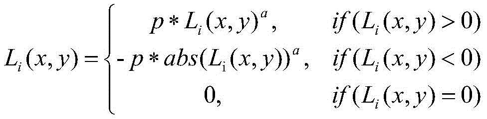
the image detail enhancement is to perform mathematical operation on each layer of image of the Laplacian pyramid, so as to improve the contrast and make the outline detail more prominent. The method uses power function to enhance the image, and sets L for each pixel value of ith layer of pyramid image i (x, y), the enhanced mathematical formula is as follows:

because the size of the image of the laplacian pyramid close to the pyramid tip is small, the profile details are very limited, and a large number of profile details are concentrated in the lowest 3 layers of the laplacian pyramid, the coefficient p in the formula can be taken according to the following formula:
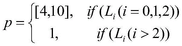
the value range of p in the 3 lowest layer image (i =0,1, 2) of the laplacian pyramid is p ∈ [4,10], and the larger the value is, the more obvious the enhancement effect is. The value range of a in the formula is a epsilon (0, 1), and the smaller the value of a, the more obvious the enhancement effect is.
The image reconstruction is fused into the inverse process of decomposition of a Gaussian pyramid and a Laplacian pyramid, and firstly, a Gaussian pyramid tip layer image G is subjected to Lev_Max Moving to the pyramid tip of the laplacian pyramid, and then reconstructing the whole image is performed only for the laplacian pyramid.
Step 4.1: image reconstruction: starting from the image of the tower apex layer, the specific reconstruction steps are as follows:
step 4.1.1. For the upper layer image L i Up-sampling by bilinear interpolation, so that the image size is equal to that of the lower layer image L i+1 And the consistency is maintained.
Step 4.1.2. Mixing L i And L i+1 Adding, replacing the result of the addition with the original L i+1 I.e. L i+1 =L i +L i+1 . Increase i by 1 and then re-execute step 1.
Lev _ Max iterations are carried out on the steps, and finally, an enhanced image L with the size consistent with that of the original image can be obtained 0 。
Step 4.2: due to the enhanced image L 0 The data type is a floating point type and needs to be converted into the original 12-bit or 16-bit integer type. Let the converted image be E, and the pixel value range be E (x, y) E [0 max ]. The conversion formula is as follows:
E(x,y)=INT(E max *(L 0 (x,y)-L min )/(L max -L min ))
INT () in the formula is a rounding operation, E max For the maximum pixel value of the converted 12-bit or 16-bit image, if 16-bit, E max 65535 was taken. L is max And L min Are respectively L before conversion 0 The maximum and minimum of the middle pixel gray scale.
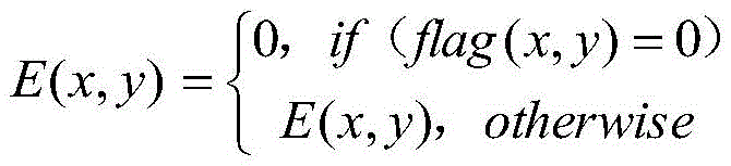
Step 4.3: the background area pixel in the enhanced image E after conversion is a non-0 value, so that the background needs to be removed, that is, the background area pixel value is set to 0, and the following formula is adopted:
step 4.4: background reduction: after the background is removed, the background image bak in the previous image segmentation step 4 is added, so that the final enhanced image which is consistent with the original image background can be obtained, and the formula is as follows:
E(x,y)=E(x,y)+bak(x,y)。
the invention has the advantages that: the method is based on X-ray image enhancement of an image pyramid, and comprises the steps of carrying out hierarchical decomposition on input X-ray images with different resolutions, carrying out targeted enhancement processing on detail images of all layers obtained through decomposition, finally carrying out reconstruction and fusion on all the enhanced hierarchical images, and finally outputting enhanced images with the same resolution, so that detail outlines with small original pixel values in the images are clear and visible.
Drawings
FIG. 1 is a block flow diagram of the present method;
FIG. 2 is a schematic block diagram of the construction of a Gaussian pyramid and a Laplacian pyramid;
fig. 3 is a diagram of image power function enhancement effect.
Detailed Description
An X-ray image enhancement method based on an image pyramid comprises the following steps:
the purpose of image segmentation is to segment the original image into a target image, in which the object to be scanned is imaged and called the target, and a background image, in which the region outside the target object is called the background. Since the X-ray in the background is not absorbed by any object, the gray value of its pixel is large, appearing as a white area. The target image segmentation sets the pixel value of the background area to 0, and the pixel value of the target object is kept unchanged. In the background image segmentation, the pixel value of a background area is kept unchanged, and the pixel value of a target object is set to be 0. The subsequent image enhancement processing of the method is only carried out aiming at the target image.
Step 1.1: a division threshold thr is set.
thr=c*Max。
The value range of the coefficient c is c ∈ [0.85,0.95], and Max is the maximum value of the original image src.
Step 1.2: and creating a flag image flag which is consistent with the original image size and data type, wherein all data positions of all pixel values in the image are set to be 1.
Step 1.3: and generating a final flag map flag according to the threshold thr. And setting the value of each pixel of the generated final flag map flag as flag (x, y), and setting the value of each pixel of the original image src as src (x, y), wherein the operation formula is as follows:

step 1.4: obtaining a target image dst and a background image bak according to the flag obtained in the step 1.3, wherein the target image dst is obtained by adopting a formula:
the background image bak is obtained by adopting a formula:
step 2, image pyramid construction:
the image pyramid construction is to decompose the target image dst into a group of image sequences with different resolutions by a downsampling mode. The image with the highest resolution is located at the bottom layer, called pyramid bottom, and the image with the lowest resolution is located at the top layer, called pyramid tip. The pyramid is from bottom to top, the image size is gradually reduced, the width and height of the lower layer image are 2 times of the width and height of the upper layer image, namely the area of the lower layer image is 4 times of the upper layer image. And constructing a pyramid of the target image dst to finally obtain a Gaussian pyramid and a Laplacian pyramid.
Step 2.1: and normalizing the target image dst, and normalizing the 12-bit or 16-bit integer data of the dst into floating point type data with the value range of [0,1.0], so that the mathematical operation of subsequent enhancement processing is facilitated. The normalization processing formula is as follows: dst (x, y) = (dst (x, y) -Minval)/(Maxval-Minval)
Maxval and Minval in the formula are the maximum value and the minimum value of the pixel gray scale in the target image dst before normalization respectively.
Step 2.2: calculating the maximum layer number Lev _ Max of the pyramid which can be constructed by the target image dst, and if the size of the pyramid tip layer image is more than or equal to 2 multiplied by 2, calculating the formula as follows:
Lev_Max=[ln(min(width,height))/ln2]
in the formula, min (width, height) is the smaller value of the width and the height of the target image dst.
Step 2.3: a gaussian pyramid is constructed. The gaussian pyramid is a series of images arranged in a pyramid shape obtained by gaussian blurring and downsampling, and the target image dst normalized in the step 2.1 is taken as the 0 th layer (bottom) of the gaussian pyramid. Assuming that the ith, where i =0,1, \8230, the Lev _ Max-1 layer image can obtain an i +1 layer image through a gaussian blur, down-sampling process. The specific construction steps are as follows:
step 2.3.1 use of 5X 5 Gauss template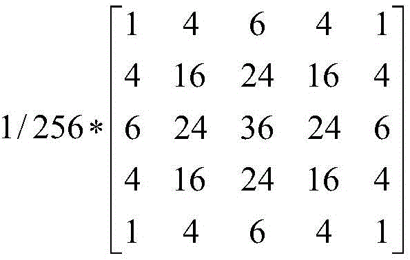 And performing Gaussian kernel convolution on the i-layer image.
Step 2.3.2, down-sampling: and removing all even rows and columns of the convolved image to obtain an i +1 layer image. The i +1 layer image is 1/4 of the i layer image.
Lev _ Max iterations are carried out on the steps, so that the whole Gaussian pyramid of the image can be obtained, and G is set i Where i =0,1,2 \8230, lev _ Max.
Step 2.4: a laplacian pyramid is constructed. The laplacian pyramid is a series of images arranged in a pyramid shape, which are obtained by upsampling each layer of image (except for the 0 th layer) on the basis of the laplacian pyramid and then subtracting the images of the lower layer of the image. Let Laplacian pyramid be L i The mathematical formula constructed is as follows:
L i =G i -Up(G (i+1) )
up (G) in the formula (i+1) ) For the up-sampling processing, namely, the width and the height of the image are increased to 2 times of the original image, a bilinear interpolation method is used for filling blank pixel points of the up-sampled image, the area of the processed image is 4 times of the original image, and finallyObtain the Laplacian pyramid L i Where i =0,1,2 \8230, lev _ Max-1. It can be seen that the gaussian pyramid has more pyramid images than the laplacian pyramid. The Laplace pyramid actually obtains a series of detail images of the image under different scales (resolutions), namely the outline details of the target object, and the value range of the image pixel is [ -1,1]。
And 3, enhancing image details:
the image detail enhancement is to perform mathematical operation on each layer of image of the Laplacian pyramid, so as to improve the contrast and make the outline detail more prominent. The method uses a power function to enhance the image, and sets L for each pixel value of the ith layer of image of the pyramid i (x, y), the enhanced mathematical formula is as follows:

because the size of the image of the laplacian pyramid close to the pyramid tip is small, the profile details are very limited, and a large number of profile details are concentrated in the lowest 3 layers of the laplacian pyramid, the coefficient p in the formula can be taken according to the following formula:
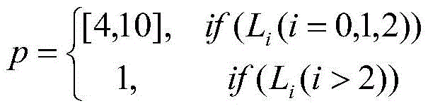
the value range of p in the 3 lowest layer image (i =0,1, 2) of the laplacian pyramid is p ∈ [4,10], and the larger the value is, the more obvious the enhancement effect is. The value range of a in the formula is a epsilon (0, 1), and the smaller the value of a is, the more obvious the enhancement effect is. When p =1, a =0.5, the power function enhancement effect is as shown in fig. 3.
The image reconstruction is fused into the inverse process of decomposition of the Gaussian pyramid and the Laplacian pyramid, firstly, the sharp-layer image G of the Gaussian pyramid is processed Lev_Max Moving to the pyramid tip of the laplacian pyramid, and then reconstructing the whole image is performed only for the laplacian pyramid.
Step 4.1: image reconstruction: starting from the image of the tower apex layer, the specific reconstruction steps are as follows:
step 4.1.1. For the upper layer image L i Up-sampling by bilinear interpolation, so that the image size is equal to that of the lower layer image L i+1 And the consistency is maintained.
Step 4.1.2. Mixing L i And L i+1 Adding, replacing the result of the addition with the original L i+1 I.e. L i+1 =L i +L i+1 . Increase i by 1 and then re-execute step 1.
Lev _ Max iterations are carried out on the steps, and finally, an enhanced image L with the size consistent with that of the original image can be obtained 0 。
Step 4.2: due to the enhanced image L 0 The data type is floating point type and needs to be converted into the original 12-bit or 16-bit integer type. Let the converted image be E, and the pixel value range be E (x, y) E [0 max ]. The conversion formula is as follows:
E(x,y)=INT(E max *(L 0 (x,y)-L min )/(L max -L min ))
INT () in the formula is a rounding operation, E max For the maximum pixel value of the converted 12-bit or 16-bit image, if 16-bit, E max 65535 was taken. L is max And L min Are respectively L before conversion 0 The maximum and minimum of the middle pixel gray scale.
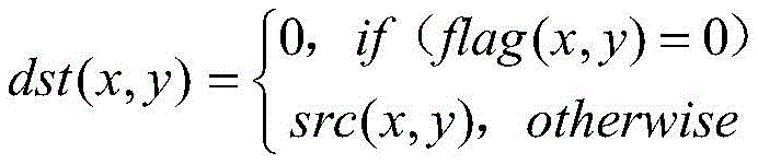
Step 4.3: the background area pixel in the enhanced image E after conversion is a non-0 value, so that the background needs to be removed, that is, the background area pixel value is set to 0, and the following formula is adopted:

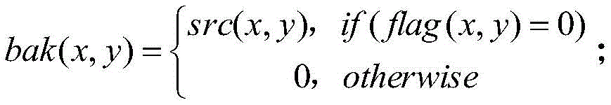
step 4.4: background reduction: after the background is removed, the background image bak in the previous image segmentation step 4 is added, so that the final enhanced image which is consistent with the original image background can be obtained, and the formula is as follows:
E(x,y)=E(x,y)+bak(x,y)。
Claims (1)
1. an X-ray image enhancement method based on an image pyramid comprises the following steps,
step 1, image segmentation:
in the X-ray image, an object to be scanned is called a target after being imaged, and a region outside the target object is called a background; since the X-ray in the background is not absorbed by any object, the gray value of its pixel is large, appearing as a white area; the target image segmentation is to set the pixel value of a background area to be 0, and the pixel value of a target object is kept unchanged; in the background image segmentation, the pixel value of a background area is kept unchanged, and the pixel value of a target object is set to be 0; the subsequent image enhancement processing of the method is only carried out aiming at the target image;
step 1.1: setting a segmentation threshold thr
thr=c*Max,
Wherein the value range of the coefficient c is c ∈ [0.85,0.95], and Max is the maximum value of the original image src;
step 1.2: newly building a flag image flag which is consistent with the original image size and data type, wherein all data positions of all pixel values in the image are set as 1;
step 1.3: and generating a final flag map flag according to the threshold thr, setting the value of each pixel of the final flag map flag as flag (x, y), setting the value of each pixel of the original image src as src (x, y), and using the following operation formula:

step 1.4: obtaining a target image dst and a background image bak according to the flag obtained in the step 1.3, wherein the target image dst is obtained by adopting a formula:
the background image bak is obtained by adopting a formula:

step 2, image pyramid construction:
the image pyramid construction is that a target image dst is decomposed into a group of image sequences with different resolutions in a down-sampling mode, an image with the largest resolution is positioned at the bottom layer and is called a pyramid bottom, an image with the smallest resolution is positioned at the top layer and is called a pyramid tip, the pyramid is from bottom to top, the image size is gradually decreased, the width and height of the lower layer image are 2 times of those of the upper layer image, namely the area of the lower layer image is 4 times of those of the upper layer image, and the pyramid construction of the target image dst finally obtains a Gaussian pyramid and a Laplacian pyramid;
step 2.1: the normalization processing is carried out on the target image dst, and the 12-bit or 16-bit integer data of the dst is normalized to the floating point type data with the value range of [0,1.0], so that the mathematical operation of the subsequent enhancement processing is facilitated, and the normalization processing formula is as follows: dst (x, y) = (dst (x, y) -Minval)/(Maxval-Minval)
Maxval and Minval in the formula are respectively the maximum value and the minimum value of the pixel gray scale in the target image dst before normalization;
step 2.2: calculating a target image dst to construct the maximum layer number Lev _ Max of the pyramid, and setting the size of the pyramid tip layer image to be more than or equal to 2 multiplied by 2, then calculating the formula as follows:
Lev_Max=[ln(min(width,height))/ln2]
in the formula, min (width, height) is the smaller value of the width and the height of the target image dst;
step 2.3: constructing a Gaussian pyramid: the Gaussian pyramid is a series of images arranged in a pyramid shape obtained through Gaussian blur and downsampling, the target image dst normalized in the step 2.1 is used as the bottom of the Gaussian pyramid, and the ith image is assumed to be processed through the Gaussian blur and downsampling, wherein i =0,1, \ 8230;, and an i +1 layer of image can be obtained through a Lev _ Max-1 layer, and the specific construction steps are as follows:
step 2.3.1 use of 5X 5 Gauss template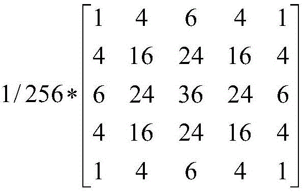 For i-layer imagePerforming line Gaussian kernel convolution;
step 2.3.2. Downsampling: removing all even rows and columns of the convolved image to obtain an i +1 layer image, wherein the i +1 layer image is 1/4 of the i layer image,
lev _ Max iteration is carried out on the steps, so that the whole Gaussian pyramid of the image can be obtained, and G is set i Wherein i =0,1,2 \8230, lev _ Max;
step 2.4: constructing a Laplacian pyramid: the Laplacian pyramid is a series of images arranged in a pyramid shape, which are obtained by up-sampling each layer of image except the 0 th layer on the basis of the Gaussian pyramid and then subtracting the images from the lower layer of image, and the Laplacian pyramid is L i The mathematical formula constructed is as follows:
L i =G i -Up(G (i+1) )
up (G) in the formula (i+1) ) For the upsampling treatment, namely the width and the height of the image are increased to 2 times of the original image, filling blank pixel points of the upsampled image by using a bilinear interpolation method, wherein the area of the upsampled image is 4 times of that of the original image, and finally obtaining the Laplacian pyramid L i Wherein i =0,1,2 \8230, lev _ Max-1, it can be seen that the Gaussian pyramid has more pyramid images than the Laplacian pyramid, the Laplacian pyramid actually obtains a series of detailed images of the images under different scales, namely the contour details of the target object, and the value range of the image pixels is [ -1,1,1 [ -1];
And 3, enhancing image details:
the image detail enhancement is to carry out mathematical operation on each layer of image of the Laplacian pyramid to improve the contrast ratio and make the outline detail more prominent i (x, y), the enhanced mathematical formula is as follows:
because the image size of the laplacian pyramid close to the pyramid tip is small, the outline details are very limited, and a large number of outline details are concentrated in the lowest 3 layers of the laplacian pyramid, the coefficient p in the formula can be taken according to the following formula:

the value range of p in the 3 layers of images at the bottom of the Laplacian pyramid is p belonging to [4,10], the enhancement effect is more obvious when the value is larger, the value range of a in the formula is a belonging to (0, 1), and the enhancement effect is more obvious when the value of a is smaller; step 4, image reconstruction fusion
The image reconstruction is fused into the inverse process of decomposition of a Gaussian pyramid and a Laplacian pyramid, and firstly, a Gaussian pyramid tip layer image G is subjected to Lev_Max Moving to the pyramid tip of the Laplacian pyramid, and then reconstructing the whole image only aiming at the Laplacian pyramid;
step 4.1: image reconstruction: starting from the image of the tower apex layer, the specific reconstruction steps are as follows:
step 4.1.1. For the upper layer image L i The upsampling is performed by bilinear interpolation, so that the image size is equal to that of the lower layer image L i+1 Keeping consistent;
step 4.1.2. Mixing L i And L i+1 Adding, replacing the result of the addition with the original L i+1 I.e. L i+1 =L i +L i+1 Increasing i by 1, and then executing the step 1 again;
lev _ Max iterations are carried out on the steps, and finally, an enhanced image L with the size consistent with that of the original image can be obtained 0 ;
Step 4.2: due to the enhanced image L 0 The data type is floating point type, it needs to be converted into original 12-bit or 16-bit integer type, the converted image is E, the pixel value range is E (x, y) is E [0, E ] max ]The conversion formula is as follows:
E(x,y)=INT(E max *(L 0 (x,y)-L min )/(L max -L min ))
INT () in the formula is a rounding operation, E max For the maximum pixel value of the converted 12-bit or 16-bit image, if 16-bit, E max Taking 65535,L max And L min Are respectively L before conversion 0 The maximum value and the minimum value of the gray scale of the middle pixel;
step 4.3: the background area pixel in the enhanced image E after conversion is a non-0 value, so that the background needs to be removed, that is, the background area pixel value is set to 0, and the following formula is adopted:

step 4.4: background reduction: after the background is removed, the background image bak in step 1.4 is added to obtain a final enhanced image which keeps consistent with the background of the original image, and the formula is as follows:
E(x,y)=E(x,y)+bak(x,y)。
Priority Applications (1)
| Application Number | Priority Date | Filing Date | Title |
|---|---|---|---|
| CN201910247876.9A CN110021031B (en) | 2019-03-29 | 2019-03-29 | X-ray image enhancement method based on image pyramid |
Applications Claiming Priority (1)
| Application Number | Priority Date | Filing Date | Title |
|---|---|---|---|
| CN201910247876.9A CN110021031B (en) | 2019-03-29 | 2019-03-29 | X-ray image enhancement method based on image pyramid |
Publications (2)
| Publication Number | Publication Date |
|---|---|
| CN110021031A CN110021031A (en) | 2019-07-16 |
| CN110021031B true CN110021031B (en) | 2023-03-10 |
Family
ID=67190212
Family Applications (1)
| Application Number | Title | Priority Date | Filing Date |
|---|---|---|---|
| CN201910247876.9A Active CN110021031B (en) | 2019-03-29 | 2019-03-29 | X-ray image enhancement method based on image pyramid |
Country Status (1)
| Country | Link |
|---|---|
| CN (1) | CN110021031B (en) |
Families Citing this family (14)
| Publication number | Priority date | Publication date | Assignee | Title |
|---|---|---|---|---|
| CN110598613B (en) * | 2019-09-03 | 2022-10-25 | 长安大学 | A kind of highway fog monitoring method |
| CN111104841B (en) * | 2019-09-16 | 2024-09-10 | 平安科技(深圳)有限公司 | Violence behavior detection method and system |
| CN110942431B (en) * | 2019-10-31 | 2022-08-30 | 南京邮电大学 | Image detail enhancement method |
| CN113724144B (en) * | 2020-05-22 | 2024-08-09 | 北京小米移动软件有限公司 | Image processing method and image signal processor on terminal equipment |
| CN112101376B (en) * | 2020-08-14 | 2024-10-22 | 北京迈格威科技有限公司 | Image processing method, device, electronic device and computer readable medium |
| CN112053279A (en) * | 2020-09-03 | 2020-12-08 | 五邑大学 | Dimension reduction method and device for hyperspectral image and storage medium |
| CN112381736B (en) * | 2020-11-17 | 2024-08-20 | 深圳市歌华智能科技有限公司 | Image enhancement method based on scene segmentation |
| CN112561909B (en) * | 2020-12-28 | 2024-05-28 | 南京航空航天大学 | A method for generating image adversarial samples based on fusion mutation |
| CN112884855A (en) * | 2021-01-13 | 2021-06-01 | 中广核贝谷科技有限公司 | Processing method and device for security check CT reconstructed image |
| CN112967209B (en) * | 2021-04-23 | 2022-08-02 | 上海埃尔顿医疗器械有限公司 | Endoscope image blood vessel texture enhancement method based on multiple sampling |
| CN114841903B (en) * | 2022-07-05 | 2022-09-09 | 黄海造船有限公司 | Ship body surface corrosion degree evaluation method based on image processing |
| CN116777768B (en) * | 2023-05-25 | 2024-05-31 | 珠海移科智能科技有限公司 | A robust and efficient scanned document image enhancement method and device |
| CN118587271A (en) * | 2024-07-01 | 2024-09-03 | 中国地质大学(北京) | A rock CT image analysis and processing method |
| CN118501187A (en) * | 2024-07-16 | 2024-08-16 | 宁波东方电缆股份有限公司 | Quality detection method and system for ocean umbilical cable insulating layer |
Citations (11)
| Publication number | Priority date | Publication date | Assignee | Title |
|---|---|---|---|---|
| WO2000013407A1 (en) * | 1998-08-28 | 2000-03-09 | Sarnoff Corporation | Method and apparatus for electronically enhancing images |
| CN1889125A (en) * | 2006-07-26 | 2007-01-03 | 深圳市嘉易通医疗科技有限公司 | Medical radiation image detail enhancing method |
| DE102010008630A1 (en) * | 2010-02-18 | 2011-08-18 | ESW GmbH, 22880 | Method for processing multi-channel image recordings for the detection of hidden objects in opto-electronic person control |
| CN102473290A (en) * | 2009-06-29 | 2012-05-23 | 汤姆逊许可证公司 | Contrast enhancement |
| CN103578091A (en) * | 2013-10-10 | 2014-02-12 | 中国科学院上海技术物理研究所 | Infrared polarization image fusion method based on Laplacian pyramid |
| US8811764B1 (en) * | 2012-10-25 | 2014-08-19 | Google Inc. | System and method for scene dependent multi-band blending |
| CN104408700A (en) * | 2014-11-21 | 2015-03-11 | 南京理工大学 | Morphology and PCA (principal component analysis) based contourlet fusion method for infrared and visible light images |
| CN104504666A (en) * | 2015-01-16 | 2015-04-08 | 成都品果科技有限公司 | Tone mapping method based on Laplacian pyramid |
| CN106960428A (en) * | 2016-01-12 | 2017-07-18 | 浙江大立科技股份有限公司 | Visible ray and infrared double-waveband image co-registration Enhancement Method |
| CN109035166A (en) * | 2018-07-16 | 2018-12-18 | 国网四川省电力公司巴中供电公司 | Electrical equipment infrared image enhancing method based on non-lower sampling shearing wave conversion |
| CN109064501A (en) * | 2018-09-14 | 2018-12-21 | 南京理工技术转移中心有限公司 | A kind of working method of sewage treatment monitoring system |
Family Cites Families (2)
| Publication number | Priority date | Publication date | Assignee | Title |
|---|---|---|---|---|
| US8411938B2 (en) * | 2007-11-29 | 2013-04-02 | Sri International | Multi-scale multi-camera adaptive fusion with contrast normalization |
| US9129277B2 (en) * | 2011-08-30 | 2015-09-08 | Digimarc Corporation | Methods and arrangements for identifying objects |
-
2019
- 2019-03-29 CN CN201910247876.9A patent/CN110021031B/en active Active
Patent Citations (11)
| Publication number | Priority date | Publication date | Assignee | Title |
|---|---|---|---|---|
| WO2000013407A1 (en) * | 1998-08-28 | 2000-03-09 | Sarnoff Corporation | Method and apparatus for electronically enhancing images |
| CN1889125A (en) * | 2006-07-26 | 2007-01-03 | 深圳市嘉易通医疗科技有限公司 | Medical radiation image detail enhancing method |
| CN102473290A (en) * | 2009-06-29 | 2012-05-23 | 汤姆逊许可证公司 | Contrast enhancement |
| DE102010008630A1 (en) * | 2010-02-18 | 2011-08-18 | ESW GmbH, 22880 | Method for processing multi-channel image recordings for the detection of hidden objects in opto-electronic person control |
| US8811764B1 (en) * | 2012-10-25 | 2014-08-19 | Google Inc. | System and method for scene dependent multi-band blending |
| CN103578091A (en) * | 2013-10-10 | 2014-02-12 | 中国科学院上海技术物理研究所 | Infrared polarization image fusion method based on Laplacian pyramid |
| CN104408700A (en) * | 2014-11-21 | 2015-03-11 | 南京理工大学 | Morphology and PCA (principal component analysis) based contourlet fusion method for infrared and visible light images |
| CN104504666A (en) * | 2015-01-16 | 2015-04-08 | 成都品果科技有限公司 | Tone mapping method based on Laplacian pyramid |
| CN106960428A (en) * | 2016-01-12 | 2017-07-18 | 浙江大立科技股份有限公司 | Visible ray and infrared double-waveband image co-registration Enhancement Method |
| CN109035166A (en) * | 2018-07-16 | 2018-12-18 | 国网四川省电力公司巴中供电公司 | Electrical equipment infrared image enhancing method based on non-lower sampling shearing wave conversion |
| CN109064501A (en) * | 2018-09-14 | 2018-12-21 | 南京理工技术转移中心有限公司 | A kind of working method of sewage treatment monitoring system |
Non-Patent Citations (2)
| Title |
|---|
| Improved multiscale image enhancement via Laplacian pyramid;Tao Mei 等;《Second International Conference on Image and Graphics》;20020731;402-407 * |
| 基于高斯-拉普拉斯金字塔的DR图像增强改进算法研究;朱伟 等;《中国医疗器械杂志》;20190130;第43卷(第1期);10-13 * |
Also Published As
| Publication number | Publication date |
|---|---|
| CN110021031A (en) | 2019-07-16 |
Similar Documents
| Publication | Publication Date | Title |
|---|---|---|
| CN110021031B (en) | X-ray image enhancement method based on image pyramid | |
| CN101939763B (en) | Method for generating multi-scale contrast-enhanced images | |
| JP2024056701A (en) | Classification and 3D modeling of 3D dentofacial structures using deep learning methods | |
| CN105931201B (en) | A method of image subjective visual effect enhancement based on wavelet transform | |
| CN101821775B (en) | Method of generating multiscale contrast enhanced image | |
| US8526753B2 (en) | Method of enhancing the contrast of an image | |
| Pandey et al. | Enhancing the quality of satellite images by preprocessing and contrast enhancement | |
| Gou et al. | Gradient regularized convolutional neural networks for low-dose CT image enhancement | |
| CN103093433A (en) | Natural image denoising method based on regionalism and dictionary learning | |
| CN107292845B (en) | Standard deviation pyramid-based dynamic image noise reduction method and device | |
| CN111882503A (en) | Image noise reduction method and application thereof | |
| CN101889295B (en) | Method for generating multi-scale contrast-enhanced images | |
| CN104182939B (en) | Medical image detail enhancement method | |
| Chen et al. | Attention-based broad self-guided network for low-light image enhancement | |
| Jiang et al. | Rep-mamba: Re-parameterization in vision mamba for lightweight remote sensing image super-resolution | |
| CN106910166B (en) | Image processing method and device | |
| Ashaduzzman et al. | Using deep learning super-resolution for improved segmentation of sem biofilm images | |
| CN114202464B (en) | X-ray CT local high-resolution imaging method and device based on deep learning | |
| CN119251086B (en) | X-ray image inversion enhancement method based on deep neural network | |
| CN107274372B (en) | Pyramid local contrast-based dynamic image enhancement method and device | |
| CN102073991B (en) | The method of the contrast of the spatial localization sign in enhancing image | |
| WO2025103848A1 (en) | Generating and using synthetic training data | |
| WO2022027216A1 (en) | Image denoising method and application thereof | |
| Zhang | A selection of image processing techniques: from fundamentals to research front | |
| Anjum et al. | A Novel Approach to Super-Resolution and Denoising: Refining Medical Image quality and Diagnostic Textual |
Legal Events
| Date | Code | Title | Description |
|---|---|---|---|
| PB01 | Publication | ||
| PB01 | Publication | ||
| SE01 | Entry into force of request for substantive examination | ||
| SE01 | Entry into force of request for substantive examination | ||
| GR01 | Patent grant | ||
| GR01 | Patent grant |