CN110017801B - Cooperative measuring gauge system for multi-axis position measurement - Google Patents
Cooperative measuring gauge system for multi-axis position measurement Download PDFInfo
- Publication number
- CN110017801B CN110017801B CN201811608111.5A CN201811608111A CN110017801B CN 110017801 B CN110017801 B CN 110017801B CN 201811608111 A CN201811608111 A CN 201811608111A CN 110017801 B CN110017801 B CN 110017801B
- Authority
- CN
- China
- Prior art keywords
- measurement
- fpmd
- combined
- spmd
- axis
- Prior art date
- Legal status (The legal status is an assumption and is not a legal conclusion. Google has not performed a legal analysis and makes no representation as to the accuracy of the status listed.)
- Active
Links
- 238000005259 measurement Methods 0.000 title claims abstract description 437
- 238000005070 sampling Methods 0.000 claims abstract description 62
- 238000004891 communication Methods 0.000 claims abstract description 58
- 238000012545 processing Methods 0.000 claims description 40
- 238000000034 method Methods 0.000 claims description 15
- 230000004913 activation Effects 0.000 claims description 5
- 230000003213 activating effect Effects 0.000 claims description 4
- 239000000523 sample Substances 0.000 description 97
- 230000000875 corresponding effect Effects 0.000 description 68
- 230000008878 coupling Effects 0.000 description 35
- 238000010168 coupling process Methods 0.000 description 35
- 238000005859 coupling reaction Methods 0.000 description 35
- 230000007246 mechanism Effects 0.000 description 27
- 230000006870 function Effects 0.000 description 10
- 238000010586 diagram Methods 0.000 description 6
- 230000008569 process Effects 0.000 description 6
- 238000013519 translation Methods 0.000 description 5
- 230000008859 change Effects 0.000 description 3
- 230000008901 benefit Effects 0.000 description 2
- 238000004519 manufacturing process Methods 0.000 description 2
- 238000003801 milling Methods 0.000 description 2
- 230000004044 response Effects 0.000 description 2
- 230000002596 correlated effect Effects 0.000 description 1
- 238000006073 displacement reaction Methods 0.000 description 1
- 230000001976 improved effect Effects 0.000 description 1
- 230000001939 inductive effect Effects 0.000 description 1
- 230000000977 initiatory effect Effects 0.000 description 1
- 238000000926 separation method Methods 0.000 description 1
- 238000012795 verification Methods 0.000 description 1
Images


Classifications
-
- G—PHYSICS
- G01—MEASURING; TESTING
- G01B—MEASURING LENGTH, THICKNESS OR SIMILAR LINEAR DIMENSIONS; MEASURING ANGLES; MEASURING AREAS; MEASURING IRREGULARITIES OF SURFACES OR CONTOURS
- G01B3/00—Measuring instruments characterised by the use of mechanical techniques
- G01B3/22—Feeler-pin gauges, e.g. dial gauges
-
- G—PHYSICS
- G01—MEASURING; TESTING
- G01B—MEASURING LENGTH, THICKNESS OR SIMILAR LINEAR DIMENSIONS; MEASURING ANGLES; MEASURING AREAS; MEASURING IRREGULARITIES OF SURFACES OR CONTOURS
- G01B21/00—Measuring arrangements or details thereof, where the measuring technique is not covered by the other groups of this subclass, unspecified or not relevant
- G01B21/02—Measuring arrangements or details thereof, where the measuring technique is not covered by the other groups of this subclass, unspecified or not relevant for measuring length, width, or thickness
- G01B21/04—Measuring arrangements or details thereof, where the measuring technique is not covered by the other groups of this subclass, unspecified or not relevant for measuring length, width, or thickness by measuring coordinates of points
-
- G—PHYSICS
- G01—MEASURING; TESTING
- G01B—MEASURING LENGTH, THICKNESS OR SIMILAR LINEAR DIMENSIONS; MEASURING ANGLES; MEASURING AREAS; MEASURING IRREGULARITIES OF SURFACES OR CONTOURS
- G01B3/00—Measuring instruments characterised by the use of mechanical techniques
- G01B3/20—Slide gauges
-
- G—PHYSICS
- G01—MEASURING; TESTING
- G01B—MEASURING LENGTH, THICKNESS OR SIMILAR LINEAR DIMENSIONS; MEASURING ANGLES; MEASURING AREAS; MEASURING IRREGULARITIES OF SURFACES OR CONTOURS
- G01B2210/00—Aspects not specifically covered by any group under G01B, e.g. of wheel alignment, caliper-like sensors
- G01B2210/58—Wireless transmission of information between a sensor or probe and a control or evaluation unit
Landscapes
- Physics & Mathematics (AREA)
- General Physics & Mathematics (AREA)
- Length Measuring Devices With Unspecified Measuring Means (AREA)
- Arrangements For Transmission Of Measured Signals (AREA)
Abstract
The first position measurement device ("FPMD") is configured to control and operate both the standalone device mode of operation and the combined device mode of operation. During the combined device mode of operation, the FPMD input measures a sampled output through a second device provided by a second position measurement device ("SPMD") via an inter-device communication connection. The FPMD and SPMD remain in a fixed relationship (e.g., having transverse measurement axes) in the workpiece measurement arrangement. The parallel measurement data set is determined to include at least a first device measurement sample output from the FPMD and a second device measurement sample output from the SPMD corresponding to parallel first and second device sampling periods. Each parallel measurement data set is associated with a respective measurement sampling region on the workpiece. A combined measurement data output (e.g., output and/or display by the FPMD) of the current measurement sample area on the workpiece is provided based on the corresponding parallel measurement data sets.
Description
Technical Field
The present disclosure relates to precision metrology, and more particularly to a system including a position measurement device configured to produce a measurement value.
Background
Various manufacturing devices, such as milling machines or lathes, are equipped with measuring gauges, such as linear scales or other position measuring devices, for measuring the position of a machine tool or workpiece. For example, a triphent AT116 or AT715 type linear scale may be configured to detect absolute position using inductive sensing and output a signal representative of the absolute position. Such a linear scale may be configured to communicate position measurements through a Digital Readout (DRO) system. A typical DRO system may include a digital display to show the location being measured. For example, the Sanfeng KA counting system can be configured as part of a DRO suite to display the position of a linear scale coupled to a milling machine or lathe.
Various other types of measuring gauges are also available, such as hand-held or portable position measuring devices (e.g., calipers, micrometers, digital "dial" indicators, etc.), which may be configured to output measurement data to an external computer, for example. Data may be output via a wired system, such as RS 232C communication, or a wireless system using bluetooth or other wireless communication techniques. For example, a Sanfeng ABS digital display caliper, such as the model CD 15CX, may use Sanfeng U-WAVE wireless data communication to communicate with a computer configured with the Sanfeng Measur Link software. The wireless connection may be provided by an external transmitter unit attached to the handheld or portable position measurement device. Examples of such systems are disclosed in U.S. patent nos. 4,930,096 and 6,502,057.
In various applications, it may be desirable to have improved capabilities and/or modes for communicating and/or displaying measurements from position measurement devices in order to provide additional convenience, speed, and flexibility to an operator to set up a measurement system (e.g., for performing dimensional verification while manufacturing a workpiece), particularly when combined with "stand-alone" measurement devices of the existing type, to provide more complex or comprehensive measurements of a workpiece.
Disclosure of Invention
This summary is provided to introduce a selection of concepts in a simplified form that are further described below in the detailed description. This summary is not intended to identify key features of the claimed subject matter, nor is it intended to be used as an aid in determining the scope of the claimed subject matter.
A first position measurement device ("FPMD") is provided that includes a first position sensor housed in a first device housing, and a first signal processing and control portion housed in the first device housing. The first position sensor is configured to provide a first device measurement sample output representing a workpiece surface coordinate measurement along a first measurement axis with respect to the FPMD of a corresponding measurement sample region on the workpiece during a corresponding first device sampling period. The first signal processing and control section includes a first measurement sample correlation section for implementing a combined device mode of operation. The FPMD is configured to operate in an independent mode of operation during an independent period of operation and in a combined mode of operation during a combined device period of operation.
The combined device operating mode may begin by establishing an inter-device communication connection with a second position measurement device ("SPMD"). In various embodiments, the SPMD includes a second position sensor configured to provide a second device measurement sampling output that represents a workpiece surface coordinate measurement of a corresponding respective measurement sampling region on the workpiece during a corresponding second device sampling period relative to the SPMD along a second measurement axis. In various embodiments, the combined device operating mode may be available when the FPMD and SPMD are held in a fixed relationship in the workpiece measurement arrangement, with the first measurement axis and the second measurement axis arranged in a fixed axis relationship.
The combined device operating mode includes inputting a first device measurement sample output provided by the first position sensor and inputting a second device measurement sample output provided by the SPMD via the inter-device communication connection. The parallel measurement data set is determined to include at least a first device measurement sample output and a second device measurement sample output corresponding to parallel first device and second device sampling periods. Each parallel measurement data set is associated with a respective measurement sampling region on the workpiece. A combined metrology data output for a current metrology sampling area on the workpiece is provided based on the corresponding parallel metrology data sets.
Unlike the combined device mode of operation, the standalone mode of operation of the FPMD does not include establishing an inter-device communication connection with the second position measurement device SPMD. During the stand-alone mode of operation, a stand-alone measurement data output is provided that includes workpiece surface coordinate measurements of a current measurement sample area on the workpiece relative to the FPMD along at least a first measurement axis.
In some embodiments, the FPMD may further include a first user interface having a first device control element and a first device display coupled to exchange signals with the first signal processing and control portion. In some such embodiments, the first device control element and the first device display are contained in the first device housing (e.g., in a digital dial gauge, a digital height gauge, or the like). In some embodiments, the first device display is controlled by the first signal processing and control portion, during the independent mode of operation only a single axis coordinate measurement is displayed on the first device display, and during the combined mode of operation the combined mode display format on the first device display displays both axis coordinate measurements.
In various applications, the various features outlined above may substantially reduce or simplify the hardware and/or software components and/or system configuration effort required by a user to assemble various independently competent devices into an integrated measurement system. That is, by relying on the mode of operation of the assembly device built into the FPMD and always available, the aforementioned devices optimized to provide "stand-alone" measurements of the workpiece can be readily combined to form a measurement system for providing more complex or comprehensive combinations of measurements of the workpiece. Relatively unskilled users can also assemble such systems, if desired, without the inconvenience, complexity and expense associated with additional computer or software systems.
Drawings
1A-1C are illustrations of a first exemplary embodiment of a dimensional metrology measurement system.
Fig. 2A-2C are illustrations of a second exemplary embodiment of a dimensional metrology measurement system.
Figures 3A-3C are illustrations of a third exemplary embodiment of a dimensional metrology measurement system.
Fig. 4A-4C are illustrations of a fourth exemplary embodiment of a dimensional metrology measurement system.
Fig. 5A-5C are illustrations of a fifth exemplary embodiment of a dimensional metrology measurement system.
FIG. 6 is a block diagram of first and second position measurement devices in a dimensional metrology measurement system.
FIG. 7 is a block diagram of the user interface, signal processing and control portion, and communication portion of the first position measurement device.
FIG. 8 is a flow diagram illustrating an exemplary embodiment of a routine for operating a first position measurement device.
Detailed Description
1A-1C are illustrations of a first exemplary embodiment of a dimensional metrology measurement system 100. As shown in FIG. 1A, dimensional metrology measurement system 100 has system components including a first position measurement device ("FPMD") 110-1 and a second position measurement device ("SPMD") 110-2. In the example of FIG. 1A, FPMD 110-1 and SPMD 110-2 operate in a combined device mode of operation, and in the examples of FIGS. 1B and 1C, FPMD 110-1 and SPMD 110-2 each operate in an independent mode of operation.
As described in more detail below with respect to FIG. 6, in various embodiments, FPMD 110-1 and SPMD 110-2 each include a position sensor. In the example of FIG. 1A, FPMD 110-1 (e.g., including a dial indicator) includes a first position sensor and a first signal processing and control portion 115-1, each of which is contained or housed in a first device housing 119-1. The first position sensor is configured to provide a first device measurement sampling output indicative of workpiece surface coordinate measurements along at least a first measurement axis (e.g., along the Z-axis in the example of fig. 1A) relative to FPMD 110-1 for a corresponding measurement sampling region MSR on workpiece WP during a corresponding first device sampling period. In one example embodiment, the sensor of the FPMD 110-1 may be coupled to a probe having a probe tip PT that moves along the surface of the work piece WP, as understood by those skilled in the art. The SPMD 110-2 (e.g., including a translation sensor, such as an image correlation sensor or a non-contact sensor) includes a second position sensor configured to provide a second device measurement sampling output indicative of workpiece surface coordinate measurements along at least a second measurement axis (e.g., along the X-axis and Y-axis in the example of fig. 1A) relative to the SPMD 110-2 for a corresponding measurement sampling region MSR on the workpiece WP during a corresponding second device sampling period.
As will be described in more detail below, the combined device operating mode may include FPMD 110-1 establishing a communication connection between the devices with SPMD 110-2 that allows FPMD 110-1 to display or otherwise provide a combined measurement data output (i.e., including measurement data from both devices). In various embodiments, the combined device operating mode is available when the FPMD 110-1 and the SPMD 110-2 are held in a fixed relationship in the workpiece measurement arrangement WPMA, i.e., at least a first measurement axis (e.g., along the Z-axis) of the FPMD 110-1 and at least a second measurement axis (e.g., along the X-axis or Y-axis) of the SPMD 110-2 are arranged in a fixed axis relationship. In various embodiments, as part of the mounting arrangement 130, the FPMD 110-1 includes a first mounting portion 131-1 for mechanically coupling to a first coupling portion 136-1 of the mounting device 135, wherein the mounting device 135 further includes a second coupling portion 136-2 for mechanically coupling to a second mounting portion 131-2 of the SPMD 110-2. In the example of FIG. 1A, the mounting device 135 also includes a third coupling portion 136-3 for mechanically coupling to the third mounting portion 131-3 of the FPMD 110-1. In various embodiments, the mounting device 135 may fix the orientation of the FPMD 110-1 relative to the orientation of the SPMD 110-2 such that the first measurement axis (e.g., along the Z-axis) is transverse to the second measurement axis (e.g., along the X-axis or the Y-axis) according to a fixed axial relationship.
In various embodiments, the FPMD 110-1, the SPMD 110-2, and the mounting arrangement 130 are arranged in a work piece measurement arrangement WPMA with respect to a work piece WP, the work piece measurement arrangement WPMA being operable to provide work piece surface coordinate measurements of a plurality of measurement sample regions MSR on the work piece WP. For example, in one embodiment, the mounting device 135 can further include a fourth coupling portion 136-4 for coupling to the support element 139 (e.g., as part of a support structure or other mechanism that holds the mounting device 135, the FPMD 110-1, and the SPMD 110-2 above or otherwise relative to the work piece WP and/or work table 141, etc.). In various embodiments, workpiece stage configuration 140 can include a workpiece stage 141 and a workpiece stage motion mechanism 148, and support elements 139 can be fixed in a particular position such that any relative movement between workpiece WP and mounting arrangement 130 is provided by operation of workpiece stage motion mechanism 148. For example, workpiece stage motion mechanism 148 (e.g., comprising rollers or other motion mechanisms) can allow workpiece stage 141 to move along x and y axes that lie in a plane that is generally parallel to the surface of workpiece stage 141 on which workpiece WP is located. In various embodiments, mounting arrangement 130 may alternatively or additionally include a measurement motion mechanism 138 that allows movement of mounting arrangement 130 (e.g., along x and y axes that lie in a plane that is generally parallel to a surface of workpiece table 141 on which workpiece WP is located). It will be appreciated that movement of the mounting arrangement 130 relative to the surface of the work piece WP allows for workpiece surface coordinate measurements to be obtained for a plurality of measurement sampling regions MSR on the surface of the work piece WP.
In various embodiments, the current measurement sampling region MSR may correspond to the region being measured by FPMD 110-1 at a location or displacement sensed by the sensors of FPMD 110-1. More particularly, in the example of FIG. 1A, the current measurement sampling region MSR is shown to be located beneath, and physically contacted by, the probe tip PT of FPMD 110-1. Differently, in various embodiments, the current measurement sampling region MSR may not be located directly below, and may not be sensed directly by the second position sensor of SPMD 110-2, although sensing by translation of SPMD 110-2 along the x and y axes is correlated to a corresponding translation of probe tips PT of FPMD 110-1 along the corresponding x and y axes due to mounting arrangement 130, which fixes the position of SPMD 110-2 relative to the position of FPMD 110-1. The translation sensed by the SPMD 110-2 can be along a surface of the workpiece, as shown in the example of FIG. 1A, or, as described in more detail with reference to FIGS. 2A and 3A, in other example embodiments, it can be along a different surface (e.g., a surface of the workpiece stage 141 or another surface on which the workpiece WP is positioned or not, etc.).
In various embodiments, the coupling of FPMD 110-1 and SPMD 110-2 to mounting device 135 may include a contact activated switch to automatically activate the initiation of the combined device operating mode of FPMD 110-1 and/or the establishment of an inter-device communication connection. In various embodiments, FPMD 110-1 and SPMD 110-2 (and/or components thereof) may automatically recognize each other and initiate an inter-device communication connection when FPMD 110-1 and SPMD 110-2 are within a specified proximity of each other. In various embodiments, a determination may be made as to which position measurement device is to operate as an FPMD when two or more position measurement devices establish an inter-device communication connection or are otherwise present in the measurement system. More specifically, because the independently competent devices, designated as FPMDs, will perform the combined device operational mode, it can be determined which position measurement device will operate as an FPMD based at least in part on the capabilities of each device. For example, if two devices are each capable of operating as an FPMD, in some cases, the determination may be based at least in part on the display capabilities of the two devices. More specifically, if one of the devices has greater display capabilities (e.g., greater display control capabilities and/or display complexity or size and/or other display capabilities) for displaying the combined measurement data output (i.e., including the measurement data from both devices), then that device may be selected or otherwise designated to operate as the FPMD of the system, while the other device may be selected or otherwise designated to operate as the SPMD of the system.
In various embodiments, FPMD 110-1 may include a first user interface 112. In one embodiment shown in fig. 1, the first user interface 112 includes a first device control element 113 and a first device display 114 included in a first device housing 119-1 that may be connected to exchange signals with and be controlled by a first signal processing and control portion 115-1 housed in the first device housing 119-1. However, such embodiments are merely exemplary and not limiting. It will be appreciated that a display accessory (e.g., a smart phone, or more simply a dedicated accessory) may be closely associated with and connected to exchange signals with, and be wirelessly controlled by, the electronic measurement device (e.g., using bluetooth or WiFi signals and appropriate dedicated software routines according to known methods). Such an alternative embodiment is shown in fig. 1A, which includes a wireless signal 112C, and a first user interface 112 ' including a first device control element 113 ' and a first device display 114 '. It will be appreciated that the first user interface 112' and the elements it comprises may be connected to wirelessly exchange signals with and be controlled by the first signal processing and control portion 115-1 housed in the first device housing 119-1. In embodiments using the first user interface 112', etc., the first user interface 112 and its associated elements may be omitted from the housing 119-1 of the FPMD 110-1.
It will be appreciated that by incorporating the first signal processing and control portion 115-1 incorporated into the housing 119-1 of the FPMD 110-1, wherein the first signal processing and control portion 115-1 operates in accordance with the principles disclosed herein to manage or implement the standalone mode of operation during the standalone period of operation and to manage or implement the combined device mode of operation during the combined device period of operation, including managing operation of the first user interface 112 (112'), significant benefits are provided to the user/owner of the FPMD 110-1. In particular, such device configuration considerably reduces or simplifies the hardware and/or software components and/or the system configuration effort required by the user for assembling the various devices into the integrated measurement system. That is, by relying on the mode of operation of the assembly device built into the FPMD and always available, the aforementioned devices optimized to provide "stand-alone" measurements to a workpiece can be easily assembled to form a measurement system for providing more complex or comprehensive combinations of measurements for the workpiece. Relatively unskilled users can assemble such systems, if desired, without the inconvenience, complexity and expense associated with additional computer or software systems.
In various embodiments, first device display 114 (or 114') may include a user interface display 122, which may in some cases display measurement sample output 123 from FPMD 110-1 and SPMD 110-2 (e.g., corresponding to real-time measurement sample output). In the example of FIG. 1, user interface display 122 is shown displaying digital measurement sample outputs 123-1 and 123-2 from FPMD 110-1 and SPMD 110-2 in display areas 122-1 and 122-2, respectively. Each display area 122-1 and 122-2 also includes a respective zero setting selection element 125-1 and 125-2 configured to set the measurement value to zero. Such a zero setting selection element 125 may assist a user in determining the relative position when measuring a workpiece. In various embodiments, a single zero setting selection element (e.g., selection element 125-1) may be used to perform simultaneous zero settings for both FPMD 110-1 and SPMD 110-2 during the combined device operating mode. In various embodiments, the first device control elements 113(113 ') may include manual control button 113A and 113B (113A ' and 113B ') elements such as on the device body and/or virtual buttons in the touch screen user interface display 122, which may further include elements such as zero setting selection elements 125-1 and 125-2, and the like. In embodiments, such a first device control element 113 (113') may be used to perform various functions (e.g., for switching or scrolling between various options presented on the user interface display 122, and/or selecting same, such as for selecting between different measurement devices or modes, such as activating a combined device mode of operation and/or activating a stand-alone mode of operation, etc.).
In various embodiments, the user interface display 122 may further include a mode selection element 127 and a measurement device selection element 128. Mode select element 127 may be used to select a mode in which FPMD 110-1 will operate (e.g., a stand-alone mode of operation, a combination device mode of operation, etc.), as will be described in more detail below with reference to FIG. 7. In the embodiment of FIG. 1A, a portion or the entirety of the user interface display 122 is available to the mode selection element 127 by scrolling through the available modes in response to a left or right swipe gesture. It will be appreciated that this example is intended to be exemplary only, and not limiting, and that many alternative selection structures may be used for the mode selection element 127, such as a drop down menu or list box.
In various embodiments, the measurement device selection element 128 may be used to select one or more measurement devices (e.g., to be used as part of a combined device operating mode, etc.). In some embodiments, the measurement device selection element 128 may include an area labeled "device" that the user may hold down to reveal a device selection menu showing available measurement devices (e.g., for use as part of a combination device operating mode, etc.). In various embodiments, a selection element may be provided to allow a user to select with respect to the format and/or order in which the measurements are displayed. For example, the user may make a selection to cause the user interface display 122 to change the order in which the measurements are presented on the first device display 114-1, such as to change the order corresponding to presenting X, Y and the Z values in order on one display line (e.g., similar to those shown in data table 175D), rather than being Z values on one line (for FPMD 110-1) and X and Y values on a second line (for SPMD 110-2).
As described above, the first position sensor of FPMD 110-1 is configured to provide a first device measurement sample output 123-1, which represents a workpiece surface coordinate measurement along at least a first measurement axis (e.g., along the Z-axis) relative to FPMD 110-1, for a corresponding measurement sample region MSR on workpiece WP during a corresponding first device sample period. In various embodiments, the combined device operating mode includes the first signal processing and control portion 115-1, with the FPMD 110-1 inputting a first device measurement sample output 123-1 provided by a first position sensor, and inputting a second device measurement sample output 123-2 provided by the SPMD 110-2 via an inter-device communication connection. The parallel measurement data sets CMDS are determined to each comprise at least a first device measurement sample output 123-1 and at least a second measurement sample output 123-2 corresponding to parallel first device and second device sampling periods. Each parallel metrology data set CMDS is associated with a respective metrology sampling area MSR on the work piece WP. In various embodiments, a combined metrology data output is provided for a current metrology sampling area MSR on the workpiece WP based on a corresponding parallel metrology data set CMDS.
In the example of FIG. 1A, the combined measurement data output provided for the current survey sample area MSR on the work piece WP based on the corresponding parallel survey data set CMDS1 corresponds to the value displayed on the user interface display 122 of the first device display 114-1. More particularly, the parallel measurement data set CMDS1 may be determined to include a first device measurement sample output 123-1 (e.g., corresponding to the displayed value Z9.0000) and a second device measurement sample output 123-2 (e.g., corresponding to the displayed values X0.1581 and Y0.5075) corresponding to parallel first and second device sampling periods. In the example of fig. 1A, the parallel first and second device sampling periods are determined to be sufficiently close in time so that both correspond to and are generally indicated as occurring during "sampling period 1".
In various embodiments, FPMD 110-1 may transmit or otherwise provide the combined measurement data output to an external device (e.g., remote computer 180) instead of, or in addition to, the display of the combined measurement data output presented on user interface display 122. In the example of FIG. 1A, remote device communication connection 175 is shown established between FPMD 110-1 and remote computer 180. In various embodiments, the inter-device communication connection and/or the remote device communication connection 175 may each include at least one of a wired connection, a wireless connection, a bluetooth connection, a WiFi connection, and the like. It should be appreciated that in the configuration of FIG. 1A, only a single remote device communication connection 175 is required to the remote computer 180 (e.g., as opposed to a configuration requiring a different connection from each of the FPMD 110-1 and SPMD 110-2 to the remote computer 180). It will be appreciated that such a configuration with only a single remote device communication connection 175 may provide a number of advantages (e.g., simplified connection requirements and processing, etc.).
Data table 175D illustrates the combined measurement data output provided (e.g., transmitted) from FPMD 110-1 to remote computer 180 and/or presented on user interface display 122. As shown in data table 175D, the parallel measurement data set CMDS1 includes a first device measurement sample output 123-1 (e.g., corresponding to the displayed value Z9.0000) and a second device measurement sample output 123-2 (e.g., corresponding to the displayed values X0.1581 and Y0.5075) corresponding to parallel first and second device sampling periods (e.g., both shown as corresponding to "sampling period 1"). Similarly, the parallel measurement data set CMDS2 includes a first device measurement sample output 123-1 (e.g., corresponding to the displayed value Z8.0000) and a second device measurement sample output 123-2 (e.g., corresponding to the displayed value X0.2000 and Y0.5075) corresponding to parallel first and second device sampling periods (e.g., both indicated as corresponding to "sampling period 2"). Similarly, a parallel measurement data set CMDS3 (corresponding, for example, to the displayed values X-0.3000, Y-0.5075, and Z-8.5000, which correspond to "sampling period 3") and a parallel measurement data set CMDS4 (corresponding, for example, to the displayed values X-0.4000, Y-0.7000, and Z-7.5000, which correspond to "sampling period 4") are displayed.
In various embodiments, the determination of the parallel measurement data sets (e.g., CMDS1-CMDS4) includes the FPMD 110-1 triggering the parallel second device measurement sample output of the SPMD 110-2 at a time proximate to the parallel first device measurement sample output of the FPMD 110-1 via an inter-device communication connection. In one embodiment, FPMD 110-1 may trigger both the parallel second device measurement sample output 123-2 of SPMD 110-2 and the parallel first device measurement sample output 123-1 of FPMD 110-1 (e.g., using an inter-device communication connection). In various embodiments, the determination of the parallel measurement data sets may alternatively include inputting a plurality of second device measurement sample outputs 123-2 of the SPMD 110-2 via the inter-device communication connection, selecting as its parallel sample the second device measurement sample output 123-2 that is closest in time to the first device measurement sample output 123-1 of the FPMD 110-1, in order to determine the corresponding parallel measurement data set. For example, if two second device measurement sample outputs are input and correspond to respective times at t 1-1.0001 and t 2-2.0001, the first device measurement sample output corresponds to a time at t 2.0000, and the second device measurement sample output corresponding to a time at t 2-2.0001 (which is closer to the time at t 2.0000) may be selected as the parallel sample.
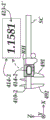
Unlike the combined device mode of operation, the standalone mode of operation does not include FPMD 110-1 establishing an inter-device communication connection with a second position measurement device (e.g., SPMD 110-2). As shown in FIG. 1B, during the independent mode of operation of FPMD 110-1, an independent measurement data output 123-1 '(e.g., corresponding to a value of 8.9000) is provided (e.g., in first device display 114-1) that includes a workpiece surface coordinate measurement of a current measurement sample area MSR' on workpiece WP along at least a first measurement axis relative to FPMD 110-1. Similarly, as shown in FIG. 1C, during the independent mode of operation of the SPMD 110-2, an independent measurement data output 123-2' (e.g., corresponding to values of 1.1581 and 0.5075) is provided (e.g., transmitted from the SPMD 110-2) that includes workpiece surface coordinate measurements along at least a second measurement axis (e.g., corresponding to two measurement axes in this example) relative to the SPMD 110-2. It will be appreciated that in the configurations of fig. 1B and 1C, the relative orientation of the measurement axes (e.g., with respect to the X, Y or Z-axis) may be unknown. It should be appreciated that, unlike the combined values of the data table 175D of FIG. 1A corresponding to parallel measurement data sets (e.g., CMDS1-CMDS4), the independent measurement data outputs 123-1 'and 123-2' may not be combinable in a similar manner (e.g., due to unknown relative orientations and positions of the FPMD 110-1 and SPMD 110-2, and/or unknown relative times at which the measurement data outputs 123-1 'and 123-2' were obtained relative to positioning, etc.).
As described in more detail below with respect to FIG. 7, in various embodiments, some calibration and/or alignment functions may be performed with respect to the orientation of the FPMD 110-1 and the SPMD 110-2. For example, a calibration function (e.g., using a calibration object or other calibration technique) may be performed to rectify/calibrate the corresponding measurement data output for greater accuracy, etc. As a further example, an alignment function may be performed with respect to the mounting arrangement 130 (e.g., including possible alignment adjustments, etc.) to ensure that the orientation (e.g., cross-orientation) of the FPMD 110-1 and the SPMD 110-2 with respect to each other is as desired.
In various embodiments, the independent mode of operation is a default mode of operation for the FPMD 110-1 (e.g., and for the SPMD 110-2), the first device control element 113 of the first user interface 112 may include a combined device mode of operation activation element 113A, and/or the mode selection element 127 may be used to select a mode (e.g., for activating a combined device mode of operation in the signal processing and control portion 115-1 housed in the housing 119-1 of the FPMD 110-1), and so forth. In various embodiments, the FPMD 110-1 and the SPMD 110-2 may each be independent measurement devices operable to provide workpiece measurements independently of one another without control from a remote computer (e.g., remote computer 180), and the combined device operating mode may be activated without control by the remote computer. It should be appreciated that in various embodiments, the measurement system 100 may not include the remote computer 180 (e.g., where the combined measurement data output may be presented only on the user interface display 122, etc.).
It should be appreciated that in the example of fig. 1A-1C, during the standalone mode of operation, FPMD 110-1 may only display a single axis coordinate on first device display 114-1, and during the combined device mode of operation, FPMD 110-1 may provide a combined mode output format that includes a multi-axis combined measurement data output format (e.g., including X, Y and Z-axis values) that is available when a fixed axis relationship corresponds to a transverse axis (transverse axes). In such a configuration, the multi-axis combined measurement output format may operate to take multiple parallel coordinate measurements of different measurement axes (e.g., corresponding to X, Y and the Z-axis) as a single output string (e.g., sent to the remote computer 180). In such a configuration, the multi-axis combination measurement output format may correspond to three-dimensional surface profile data, which corresponds to the surface of the work piece WP. As described above, data may be obtained by translating the work piece WP relative to the FPMD 110-1 and SPMD 110-2 (e.g., using the metrology motion mechanism 138 or the work piece stage motion mechanism 148) and obtaining parallel sets of metrology data (e.g., CMDS1-CMDS4) corresponding to a plurality of different metrology sampling areas MSRs on the surface of the work piece WP.
Fig. 2A-2C are illustrations of a second exemplary embodiment of a dimensional metrology measurement system 200. Measurement system 200 includes FPMD 110-1 and SPMD 110-2, and in the example of FIG. 2A, FPMD 110-1 and SPMD 110-2 operate in a combined device mode of operation, and in the examples of FIGS. 2B and 2C, FPMD 110-1 and SPMD 110-2 operate in independent modes of operation, respectively. Measurement system 200 has certain similarities to measurement system 100 of fig. 1, and like or similarly numbered components will be understood to operate similarly, except as otherwise described below. In general, in the various views herein, reference numerals having a similar suffix (e.g., reference numerals 1XX and 2XX having a suffix XX) may refer to like elements in general, unless otherwise indicated by the specification or text, so that a person skilled in the art can generally understand the operation of the element 2XX through a limited description based on an analogy to the previous description of the like element 1XX, and so forth.
With some differences from measurement system 100, measurement system 200 includes a mounting arrangement 230 in which FPMD 110-1 is coupled to first support element portion 239A and SPMD 110-2 is coupled to second support element portion 239B. The mounting arrangement 230 may be compared to the mounting arrangement 130 of the measurement system 100, in which the FPMD 110-1 and the SPMD 110-2 are more directly coupled to each other. As part of mounting arrangement 230, FPMD 110-1 includes a first mounting portion 131-1 for mechanically coupling to a first coupling portion 236-1 of a mounting device portion 235A. In addition, the mounting device portion 235B includes a second coupling portion 236-2 for mechanically coupling to the second mounting portion 131-2 of the SPMD 110-2.
Mounting device portion 235A further includes a third coupling portion 236-3 for coupling to support element portion 239A (e.g., as part of a support structure or other mechanism that holds mounting device portion 235A and FPMD 110-1 above or otherwise relative to workpiece WP and workpiece stage arrangement 140, etc.). The mounting device 235B also includes a fourth coupling portion 236-4 for coupling to the support element 239B (e.g., as part of a support structure or other mechanism that holds the mounting device 235B and the SPMD 110-2 above or otherwise relative to the work piece WP and/or the work piece table arrangement 140, etc.). In various embodiments, the mounting arrangement 230 fixes the orientation of the FPMD 110-1 relative to the orientation of the SPMD 110-2 such that the first measurement axis (e.g., along the z-axis) is transverse to the second measurement axis (e.g., along the x-axis or the y-axis) according to a fixed axial relationship.
In various embodiments, similar to the example of fig. 1A, support element portions 239A and 239B may be fixed at specific locations (e.g., as part of a common support frame) such that any relative movement between the work piece WP and the mounting arrangement 230 may be provided by operation of the work piece table motion mechanism 148. In various embodiments, mounting arrangement 230 may alternatively or additionally include one or more measurement motion mechanisms (e.g., similar to measurement motion mechanism 138 of fig. 1A) that allow movement of support element portions 239A and 239B for moving mounting arrangement 230 relative to workpiece WP (e.g., along x and y axes that lie in a plane that is generally parallel to a surface of workpiece table 141 on which workpiece WP is located). It will be appreciated that movement of the mounting arrangement 230 relative to the surface of the work piece WP allows for a plurality of measurement sampling region MSR work piece surface coordinate measurements on the surface of the work piece WP to be obtained.
Fig. 3A-3C are illustrations of a third exemplary embodiment of a dimensional metrology measurement system 300. Measurement system 300 includes FPMD 110-1 and SPMD 110-2, and in the example of FIG. 3A, FPMD 110-1 and SPMD 110-2 operate in a combined device mode of operation, and in the examples of FIGS. 3B and 3C, FPMD 110-1 and SPMD 110-2 each operate in an independent mode of operation. Measurement system 300 has certain similarities to measurement systems 100 and 200, and like-numbered components will be understood to operate similarly, except as otherwise described below.
With some differences from measurement system 100, measurement system 300 includes a mounting arrangement 330 in which SPMD 110-2 is positioned generally above surface SRF (i.e., in contrast to mounting arrangement 130 of measurement system 100, in which SPMD 110-2 is positioned above a portion of the surface of work piece WP). In various embodiments, surface SRF may represent a surface of a table (e.g., table 141 of fig. 1A), or another surface (e.g., a surface on which work piece WP may or may not be located). In various embodiments, surface SRF may be relatively flat, and/or may have other characteristics that allow for relatively accurate position determinations to be made by SPMD 110-2. For example, in embodiments where the SPMD 110-2 utilizes image correlation to determine location, the surface SRF may include features (e.g., texture, flatness, etc.) that allow for accurate location determination when utilizing image correlation techniques. In certain embodiments, this may be different than the configuration of the measurement system 100, for which the surface of the work piece WP may not be processable, to enable accurate position determination of the SPMD 110-2. In various embodiments, mounting arrangement 330 may be larger than mounting arrangement 130 due to the required separation of system components such that SPMD 110-2 remains on surface SRF and FPMD 110-1 remains on the surface of workpiece WP during a measurement operation.
In various embodiments, as part of mounting arrangement 330, FPMD 110-1 includes a first mounting portion 131-1 for mechanically coupling to first coupling portion 136-1 of mounting device portion 335A of mounting device 355. In various embodiments, the mounting arrangement 335 further includes a mounting arrangement portion 335B having a second coupling portion 336-2 for mechanically coupling to the second mounting portion 131-2 of the SPMD 110-2. In the example of FIG. 3A, mounting arrangement 335 further includes a third mounting arrangement portion 335C having a third coupling portion 336-3 for mechanically coupling to third mounting portion 131-3 of FPMD 110-1. In various embodiments, mounting device portion 335C may further include a fourth coupling portion 336-4 for coupling to support element 139 (e.g., as part of a support structure or other mechanism that holds mounting device 335, FPMD 110-1, and SPMD 110-2 above or otherwise relative to workpiece WP and surface SRF, etc.). In various embodiments, mounting apparatus 335 may fix the orientation of FPMD 110-1 relative to the orientation of SPMD 110-2 such that the first measurement axis (e.g., along the z-axis) is transverse to the second measurement axis (e.g., along the x-axis or the y-axis) according to a fixed axial relationship.
In various embodiments, similar to the example of FIG. 1A, surface SRF may be moved by a motion mechanism (e.g., workpiece stage motion mechanism 148 of FIG. 1A) along x and y axes that are generally parallel to surface SRF on which workpiece WP is located. In various embodiments, mounting arrangement 330 may alternatively or additionally include a measurement motion mechanism (e.g., measurement motion mechanism 138 of fig. 1A) that allows movement of mounting arrangement 330 (e.g., along x and y axes that lie in a plane that is generally parallel to surface SRF on which workpiece WP lies). It will be appreciated that movement of the mounting arrangement 330 relative to the surface of the work piece WP allows for workpiece surface coordinate measurements to be obtained for a plurality of measurement sampling regions MSR on the surface of the work piece WP.
Fig. 4A-4C are illustrations of a fourth exemplary embodiment of a dimensional metrology measurement system 400. As will be described in more detail below, measurement system 400 includes FPMD 110-1 and SPMD 410-2 (e.g., electronic calipers), and in the example of FIG. 4A, FPMD 110-1 and SPMD 410-2 operate in a combined device mode of operation, and in the examples of FIGS. 4B and 4C, FPMD 110-1 and SPMD 410-2 operate in independent modes of operation, respectively. Measurement system 400 has certain similarities to measurement systems 100, 200, and 300, and like-numbered components will be understood to operate similarly, except as otherwise described below.
For certain differences from measurement system 100, measurement system 400 includes an SPMD 410-2 (e.g., an electronic caliper) to which FPMD 110-1 is coupled. As shown in FIGS. 4A and 4C, SPMD 410-2 includes a second device display 414-2 as part of the read head RH. As part of the measurement operation, the readhead RH is slid along the scale SC, for which a sensor within the readhead RH determines a corresponding position measurement (i.e. representative of the position of the readhead RH along the scale SC) (e.g. using a linear transducer). The determined position measurement may be displayed on second device display 414-2. With respect to fig. 4C, as an example of a standalone mode of operation, a workpiece (not shown) may be located between the measurement jaw 491 (i.e. attached to the readhead RH) and the measurement jaw 492 (i.e. attached to the end of the scale SC), for which the resulting measurement may be representative of the outer dimension of the workpiece located between the jaws 491, 492.
As shown in FIG. 4A, measurement system 400 includes a mounting arrangement 430 in which FPMD 110-1 is coupled to SPMD 410-2. As part of the mounting arrangement 430, the FPMD 110-1 includes a first mounting portion 131-1 for mechanically coupling to a second mounting portion 431-1 of the SPMD 410-2. In various embodiments, the second mounting portion 431-1 may be located on or otherwise coupled to the readhead RH and/or associated measurement jaw 491 such that the FPMD 110-1 moves with the readhead RH. In such a configuration, it will be appreciated that the position of the read head RH along the second measurement axis (i.e., the measurement axis of SPMD 410-2) represents the position of the FPMD 110-1 (i.e., and the corresponding probe tip PT) along the second measurement axis. In various embodiments, a mounting device (not shown) may be used to assist in coupling FPMD 110-1 to SPMD 410-2, and may be located between, and coupled to, mounting portions 131-1 and 431-1. FPMD 110-1 further includes a third mounting portion 131-3 for coupling to support element 139. In various embodiments, a mounting device (not shown) may be used to assist in coupling FPMD 110-1 to support elements 139 and may be located between, and coupled to, mounting portions 131-3 and 139.
In various embodiments, the support elements 139 are part of a support structure or other mechanism that holds the FPMD 110-1 and SPMD 410-2 above or otherwise relative to the work piece WP and/or work table 141, or the like. In various embodiments, the support element 139 can be fixed at a particular position, wherein some relative movement between the work piece WP and the mounting arrangement 130 can be provided by operation of the work piece table motion mechanism 148. In various embodiments, additional or alternative movement of the FPMD 110-1 relative to the work piece WP can be provided by operation of a readhead RH that slides along the scale SC of the SPMD 410-2. It will be appreciated that movement of the FPMD 110-1 relative to the surface of the work piece WP allows for obtaining work piece surface coordinate measurements of a plurality of measurement sample regions MSR on the surface of the work piece WP.
It should be appreciated that in the example of FIG. 4A, the combined measurement data output provided based on the corresponding parallel measurement data sets CMDS1-CMDS4 (e.g., shown in data table 475D) comprises a two-axis combined measurement data output that is available when the fixed axis relationship corresponds to a cross-axis (i.e., a first measurement axis of FPMD 110-1 along the Z-axis is cross-referenced to a second measurement axis of SPMD 410-2 along the X-axis). In such a configuration, two-dimensional surface profile data corresponding to the surface of the workpiece is provided by a combined measurement data output corresponding to multiple instances of multiple different measurement sampling regions on the workpiece. Differently, during the respective independent mode of operation (e.g., as shown in FIGS. 4B and 4C), FPMD 110-1 and SPMD 110-2 each only display a single axis coordinate measurement on first device display 114-1 and second device display 414-2, respectively. As shown in FIG. 4A, during the combined device operating mode, FPMD 110-1 transmits to remote computer 180, and/or presents a combined mode display format/on first device display 114-1 that displays/includes two axis coordinate measurements (e.g., corresponding to X and Z axis values).
Fig. 5A-5C are illustrations of a fifth exemplary embodiment of a dimensional metrology measurement system 500. As will be described in more detail below, the measurement system 500 includes a FPMD 510-1 (e.g., a profile tracker) and a SPMD 110-2. In the example of FIG. 5A, FPMD 510-1 operates in a combined device mode of operation with SPMD 110-2, and in the examples of FIGS. 5B and 5C, FPMD 510-1 and SPMD 110-2 each operate in an independent mode of operation. Measurement system 500 has certain similarities to measurement systems 100, 200, 300, and 400, and like-numbered components will be understood to operate similarly, except as otherwise described below.
For certain differences from measurement system 100, measurement system 500 includes FPMD 510-1 (e.g., a profile tracker) with SPMD 110-2 coupled to FPMD 510-1. FPMD 510-1 includes a probe and corresponding probe tip PT' that contacts and/or otherwise moves along the surface of work piece WP, and a first device display 514-1 that displays a resulting measurement sample output 523-1. In the embodiment of FIG. 5A, in addition to providing a Z-axis measurement sample output as a function of the vertical position of the probe tip PT' when it contacts the surface of the work piece WP, FPMD 510-1 is also capable of providing a certain X-axis measurement sample output over a limited range. More specifically, FPMD 510-1 includes an internal movement mechanism IMM that is capable of providing movement of the probe tip PT and probe tip along the X-axis within a limited range (e.g., the maximum range of movement within FPMD 510-1 by the internal movement mechanism IMM).
In various embodiments, it is desirable to provide a measurement system that has a greater X-axis measurement range (e.g., for larger workpieces or other measurement surfaces, etc.) than that provided by FPMD 510-1 alone. It will be appreciated that by coupling the SPMD 110-2 to the FPMD 510-1 and utilizing a combined device mode of operation, the X-axis measurement sample outputs from both the FPMD 510-1 and the SPMD 110-2 may be combined or otherwise used to obtain a greater X-axis measurement range than provided by the FPMD 510-1 alone. In the example of fig. 5A, the parallel measurement data set CMDS1 may be determined to include a first device measurement sample output 523-1 (e.g., corresponding to the displayed values X2-0.0020 and Z-9.0000) and a second device measurement sample output 123-2 (e.g., corresponding to the displayed values X1-0.1581 and Y-0.5075) corresponding to parallel first and second device sample periods (e.g., both indicated as corresponding to "sample period 1" in data table 575D). Similarly shown are a parallel measurement data set CMDS2 (e.g., corresponding to the values X1 ═ 0.3000, Y ═ 0.5075, Z ═ 8.0000, X2 ═ 0.0020, X1+ X2 ═ 0.2030 corresponding to "sampling period 2"), a parallel measurement data set CMDS3 (e.g., corresponding to the values X1 ═ 0.3000, Y ═ 0.5075, Z ═ 8.5000, X2 ═ 0.0040, X1+ X2 ═ 0.3040 corresponding to "sampling period 3"), and a parallel measurement data set CMDS4 (e.g., corresponding to the values X1 ═ 0.4000, Y ═ 0.7000, Z ═ 7.5000, X2 ═ 0.050, X1+ X2 ═ 0.4050 corresponding to "sampling period 4").
In various embodiments, the first device display 514-1 and/or the data table 575D may display/include values corresponding to both X1 and X2, and may also or alternatively include values corresponding to X1+ X2. For example, in an alternative embodiment, during the combined device operating mode, instead of displaying each individual X1 and X2 value, first device display 514-1 may be caused to display only the X1+ X2 values (i.e., 0.1601 of parallel measurement data set CMDS1, which corresponds to the total X-axis position). Similarly, in embodiments, data corresponding to the parallel measurement data set CMDS1 transmitted by FPMD 510-1 to remote computer 180 may be made to include X1+ X2 values (i.e., 0.1601), either in addition to or instead of including each individual X1 and X2 value.
As shown in FIG. 5A, measurement system 500 includes a mounting arrangement 530, wherein FPMD 510-1 is coupled to SPMD 110-2. As part of the mounting arrangement 530, the FPMD 510-1 includes a first mounting portion 531-1 for mechanically coupling to a second mounting portion 131-2 of the SPMD 110-2. In various embodiments, a mounting device (not shown) may be used to assist in coupling the FPMD 510-1 to the SPMD 110-2, and may be located between and coupled to the mounting portions 531-1 and 131-2. The SPMD 110-2 further includes a third mounting portion 131-3 for coupling to a support element 139. In various embodiments, a mounting device (not shown) may be used to assist in coupling the SPMD 110-2 to the support element 139 and may be located between, and coupled to, the mounting portions 131-3 and 139.
In various embodiments, support elements 139 are part of a support structure or other mechanism that holds FPMD 510-1 and SPMD 110-2 above or otherwise relative to work piece WP and/or surface SRF' on which work piece WP is located, or the like. In various embodiments, the support element 139 can be fixed at a particular position, wherein some relative movement between the work piece WP and the mounting arrangement 530 can be provided by operation of a motion mechanism (e.g., the work piece table motion mechanism 148 of fig. 1A). In various embodiments, the mounting arrangement 530 may alternatively or additionally include a measurement movement mechanism (e.g., the measurement movement mechanism 138 of FIG. 1A) that allows movement of the mounting arrangement 530 relative to the work piece WP. It will be appreciated that movement of the mounting arrangement 530 relative to the surface of the work piece WP allows for workpiece surface coordinate measurements to be obtained for a plurality of measurement sampling regions MSR on the surface of the work piece WP.
It should be appreciated that in the example of FIG. 5A, the combined measurement data outputs provided based on the respective parallel measurement data sets CMDS1-CMDS4 (e.g., shown in data table 475D) include the parallel combined measurement data outputs available when the fixed axis relationship corresponds to parallel axes (parallel axes) (i.e., X2 values for the measurement axis of the corresponding FPMD 510-1 and X1 for the measurement axis of the SPMD 110-2). In such a configuration, the combined measurement data output may include coordinate measurements based on the summation of the first device measurement sample output and the second device measurement sample output (i.e., the summation of the X1 and X2 values, as shown in data table 575D). In various embodiments, the first device control element of the first user interface of FPMD 510-1 may comprise a parallel axis selection element activation element that activates the use of parallel combined measurement data output when FPMD 510-1 is operating in a combined device operating mode.
FIG. 6 is a block diagram of FPMD 110-1 and SPMD 110-2 in a dimensional metrology measurement system 600. It should be appreciated that, in various embodiments, various components of FPMD 610-1 and SPMD 610-2 may represent various components of the respective FPMD and SPMD of FIGS. 1-5, as described above. As partially shown in some examples of fig. 1-5, in various embodiments, FPMD 610-1 may be a measurement device such as a dial indicator, height gauge, contour tracker, etc., and SPMD 610-2 may be a measurement device such as a translation sensor (e.g., an image correlation sensor), caliper, etc.
As shown in FIG. 6, FPMD 610-1 includes a first position sensor 611-1, a first user interface 612-1, a first signal processing and control portion 615-1, and a first communication portion 618-1. The first position sensor 611-1 is configured to provide a first device measurement sample output representing workpiece surface coordinate measurements along at least a first measurement axis relative to the FPMD 610-1 at a respective measurement sample area on the workpiece during a respective first device sampling period. The first user interface 612-1 includes a first device control element 613-1 and a first device display 614-1. The first signal processing and control portion 615-1 includes a first measurement sample correlation portion 616-1 that is used to implement a combined device mode of operation. In various embodiments, the first signal processing and control portion 615, including the first measurement sample association portion 616, may be incorporated within the housing of the FPMD 610-1. FPMD 610-1 is configured to operate in a standalone mode of operation during a standalone period of operation and in a combined device mode of operation during a combined device period of operation.
The combined device operating mode of FPMD 610-1 may begin by establishing an inter-device communication connection 620 with SPMD 610-1. In various embodiments, the inter-device communication connection and/or the remote device communication connection 620 may include at least one of a wired connection, a wireless connection, a bluetooth connection, a WiFi connection. In various embodiments, SPMD 610-2 includes a second position sensor 611-2 configured to provide a second device measurement sampling output representing workpiece surface coordinate measurements of a respective measurement sampling region on the workpiece with respect to the SPMD along at least a second measurement axis during a respective second device sampling period. In various embodiments, the second position sensor 611-2 may comprise a non-contact sensor, or an image-related sensor, or the like. In various embodiments, SPMD 610-2 includes a second user interface 612-2, a second signal processing and control portion 615-2, and a second communication portion 618-2. The second user interface 612-2 may include a second device control element 613-2 and a second device display 614-2. The second signal processing and control portion 615-2 may include a second measurement sample association portion 616-2 that may be used to communicate with the first measurement sample association portion 616-1 of the FPMD 610-1 or otherwise implement the combined device operating mode of the SPMD 610-2.
In various embodiments, the combined device operating mode may be used when the FPMD 610-1 and the SPMD 610-2 are held in a fixed relationship in a workpiece measurement arrangement in which the first measurement axis and the second measurement axis are arranged in a fixed axis relationship (e.g., the first measurement axis is transverse to the second measurement axis, etc.). In various embodiments, the combined device operating mode includes the first signal processing and control portion 615-1 inputting a first device measurement sample output provided by the first position sensor 611-1 and inputting a second device measurement sample output provided by the SPMD 110-2 via the inter-device communication connection 620 (e.g., as a communication between the first and second communication portions 618-1 and 618-2). As described above with respect to fig. 1-5, the parallel measurement data sets are determined to include at least a first device measurement sample output and a second device measurement sample output corresponding to parallel first device and second device sampling periods. Each parallel measurement data set is associated with a respective measurement sample area on the workpiece being measured. Based on the respective sets of parallel metrology data, a combined metrology data output for the respective metrology sampling region on the workpiece is provided.
In various embodiments, the determination of the parallel measurement data sets during the combined device operating mode may include the FPMD 610-1 triggering the parallel second device measurement sample output of the SPMD 610-2 at a time proximate to the parallel first device measurement sample output of the FPMD 610-1 via the inter-device communication connection 620. In various embodiments, FPMD 610-1 may trigger the parallel second device measurement sample output of SPMD 610-2 and the parallel first device measurement sample output of FPMD 610-1 simultaneously. In alternative embodiments, the determination of the set of parallel measurement data may include inputting a plurality of second device measurement sample outputs of the SPMD 610-2 via the inter-device communication connection, selecting as its parallel samples the second device measurement sample output that is closest in time to the first device measurement sample output of the FPMD 610-1, in order to determine the set of parallel measurement data.
Unlike the combined device mode of operation, the standalone mode of operation does not include the FPMD 610-1 establishing an inter-device communication connection with a second position measurement device (e.g., SPMD 610-2). During the stand-alone mode of operation, a stand-alone measurement data output is provided that includes workpiece surface coordinate measurements of corresponding measurement sample regions MSR on the workpiece WP along at least a first measurement axis relative to the FPMD 610-1. In various embodiments, the independent mode of operation is a default mode of operation for the FPMD 610-1, and the first device control element 613-1 of the first user interface 612-1 comprises a combination device mode of operation activation element. In various embodiments, FPMD 610-1 and SPMD 610-2 are independent measurement devices operable to provide workpiece measurements independently of one another without control by a remote computer, and first signal processing and control portion 615-1, including first measurement sample association portion 616-1, is configured to activate and implement a combined device mode of operation without control from or connection to a remote computer.
FIG. 7 is a block diagram of a user interface 712, signal processing and control section 715, and communication section 718 of FPMD 710-1. It should be appreciated that in various embodiments, the illustrated components of FPMD 710-1 may represent respective portions of the user interface, signal processing and control portions, and communication portions of the respective FPMD of FIGS. 1-6 described above. As shown in fig. 7, the signal processing and control section 715 includes a stand-alone mode of operation 730, a combination device mode of operation 740, a setup control mode 750, a memory 770, and a processor 780. The independent operation mode 730 includes an independent operation mode process 731. Combined device operational mode 740 includes combined device operational mode processing 741. The setting control mode 750 includes a setting control mode processing section 751.
User input interface portion 712 includes a stand-alone operating mode display 732, a combination device operating mode display 742, and a settings control mode display 752. The independent operation mode display 732 includes an independent operation mode display and selection element 733. The combined device operating mode display 742 includes a combined device operating mode display and selection element 743. The setting control mode display 752 includes a setting control mode display and selection element 753.
In various embodiments, the independent operation mode portion 730-733 may be used to implement an independent operation mode (e.g., as shown and described above with respect to FIGS. 1B, 2B, 3B, 4B, and 5B). In various embodiments, combination device operational mode portion 740-743 may be used to implement a combination device operational mode (e.g., as shown and described above with respect to fig. 1A, 2A, 3A, 4A, and 5A). For example, the independent mode of operation process 731 can be used to process inputs from and related to a measurement sample output from a first position sensor of the FPMD. In contrast, combined device operating mode processing 741 may be used to process inputs from and relating to a measurement sample output from both the first position sensor of the FPMD and the measurement sample output received from the SPMD via the inter-device communication connection. In various embodiments, the combined device operating mode process 741 may perform operations such as determining parallel measurement data sets, combining measurement sample outputs (e.g., determining X1+ X2 in the example of fig. 5A), and so forth.
In various embodiments, as part of or independent of the combined device operational mode processing 741, some calibration and/or alignment functions may be performed with respect to the orientation of the FPMD and SPMD relative to each other. For example, an alignment function may be performed relative to the mounting arrangement (e.g., including possible alignment adjustments, etc.) to ensure the orientation of the FPMD and SPMD relative to each other (e.g., transverse measurement axis orientation). As a further example, a calibration function may be performed to rectify/calibrate the respective measurement data output (e.g., to more closely correspond to a cross-measurement axis orientation, etc.). In an example embodiment, a calibration object having known dimensions (e.g., known step heights and dimensions) may be used as part of the calibration process. More specifically, after the FPMD and the SPMD are coupled together in the mounting arrangement, the calibration object may be measured by the FPMD and the SPMD as part of the combined device operating mode, and the resulting measured values/dimensions may be compared to known values/dimensions of the calibration object. The difference between the measured and known values/dimensions may be determined and stored and/or otherwise used to perform calibration operations (e.g., to adjust the mounting arrangement and/or to adjust future measured values for greater accuracy).
The independent operation mode display 732 may be used to format and display values associated with the measured sample output from the first position sensor of the FPMD (e.g., as shown in the first device display 114 of fig. 1B, 2B, 3B, 4B, and 5B). In contrast, the combined device operating mode display 742 may be used to format and display values for the measurement sample output from the first position sensor of the FPMD as well as the measurement sample output received from the SPMD via the inter-device communication connection (e.g., as shown in the first device display 114-1 of FIGS. 1A, 1B, and 1C). In various embodiments, such processing/display by the combined device operating mode display 742 may include formatting the display to display values associated with measured sample outputs from both the FPMD and the SPMD, updating the display based on new values, and so forth.
The independent operation mode display and selection element 733 may be used to provide display and selection elements related to operation of the FPMD and measurement sample output from the first position sensor of the FPMD in the independent operation mode (e.g., as shown in fig. 1B, 2B, 3B, 4B, and 5B). In various embodiments, such display and selection elements may include elements for performing a zeroing function as part of a measurement operation, switching display modes (e.g., switching the display of measurement values between inches and millimeters, etc.). In contrast, the combined device operating mode display and selection element 743 can be used to provide a display and selection element that is related to the operation of the FPMD and the measurement sample output from the first position sensor of the FPMD during the combined device operating mode as well as the measurement sample output received from the SPMD via the inter-device communication connection (e.g., as shown in the user interface display 122 of FIGS. 1A, 1B, and 1C). In various embodiments, such display and selection elements may include first device control elements 113, such as manual control buttons on the device body and/or virtual buttons in the user interface display 122, which may further include elements such as zero setting selection elements 125-1 and 125-2, measurement device selection element 128, and the like. In various embodiments, such display and selection elements may be used to perform various functions (e.g., for switching or scrolling and/or selecting between various options presented on the user interface display 122, etc.). In various embodiments, the user may select with respect to the combination device operating mode display and with respect to the selection element 743 for the order and/or format of the measured values being displayed. For example, the user may make a selection that causes the user interface display 122 to change the order in which the measurements are presented on the first device display 114-1, such as to the order corresponding to presenting X, Y and the Z values in order on one display line (e.g., similar to those shown in data table 175D), as opposed to being Z values (for FPMD) on one line and X and Y values (for SPMD) on a second line.
In various embodiments, the set control mode portion 750-753 can be used to select between available modes (e.g., the individual operation mode 730, the combined device operation mode 740, etc.). For example, the set control mode display and selection element 753 can be used to provide display and selection elements related to operation mode selection. In various embodiments, as described above with reference to the embodiment of FIG. 1A, a portion or the entirety of the user interface display 122 may be used for the mode selection element 127 by scrolling through the available modes in response to a slide gesture to the left or right. It will be appreciated that this example is intended to be illustrative only and not limiting, and that many alternative selection structures may be used for the mode selection element 127, such as a drop down menu or list box, etc.
In embodiments, the set control mode portion 750-753 can be configured such that various actions and/or events can cause the combined device operational mode to be automatically initiated, or can automatically cause an option to be presented to a user for selecting to activate the combined device operational mode or to remain in the stand-alone operational mode. For example, in various embodiments, coupling the FPMD and SPMD to the mounting device, establishing an inter-device communication connection, or placing the FPMD and SPMD within a specified proximity of each other may cause the combined device operating mode to be automatically initiated, or the corresponding mode selection option to be automatically presented to the user.
The communication section 718 may be configured to communicate with multiple types of measurement devices and other types of devices through various wireless communication means, such as bluetooth, WiFi, cloud-based data infrastructure, and the like. As described above, during the combined device mode of operation, the communication section 718 can be used to establish an inter-device communication connection with the SPMD. The communications section 718 may be used to establish a communications connection with a remote computer.
FIG. 8 is a flow diagram illustrating an exemplary embodiment of a routine 800 for operating an FPMD. At decision block 810, a determination is made as to whether a combination device operating mode is to be initiated. If the combined device mode of operation is not to be initiated, the routine continues to a block 850 where the FPMD operates in a standalone mode of operation, as will be described in more detail below. If a combined device operating mode is to be initiated, the routine continues to block 820, where an inter-device communication connection is established with the SPMD. In various embodiments, the establishment of the inter-device communication connection may occur prior to determining whether to initiate the combined device operational mode, and in some embodiments, may cause the combined device operational mode to be initiated automatically. In various embodiments, the combined device operating mode is available when the FPMD and the SPMD are held in a fixed relationship in the workpiece measurement arrangement, with at least the first measurement axis of the FPMD and at least the second measurement axis of the SPMD arranged in a fixed axis relationship.
At block 825, a first device measurement sample output provided by a first position sensor of the FPMD is input. For example, the signal processing and control portion of the FPMD may input a measurement sample output from the first position sensor of the FPMD when the surface of the workpiece is measured. At block 830, a second device measurement sample output provided by the SPMD is input via the inter-device communication connection. At block 835, parallel measurement data sets are determined, wherein each parallel measurement data set includes at least a first device measurement sample output and at least a second device measurement sample output corresponding to a first device sampling period and a second device sampling period in parallel, each parallel measurement data set associated with a respective measurement sampling region on the workpiece. At block 840, a combined metrology data output for the current metrology sampling area on the workpiece is provided based on the corresponding parallel metrology data sets.
If it is determined at decision block 810 that the combined device operating mode is not to be initiated, the routine continues to block 850, where the routine continues in the stand-alone operating mode during which no inter-device communication connection is established with the SPMD. At block 855, a separate measurement data output is provided that includes workpiece surface coordinate measurements of a current measurement sample area on the workpiece relative to the FPMD along at least a first measurement axis.
The various embodiments described above can be combined to provide further embodiments. Any U.S. patents and U.S. patent applications referenced in this specification are hereby incorporated by reference in their entirety. Aspects of the embodiments can be modified, if necessary, to apply the concepts of the patents and applications to provide additional embodiments.
These and other changes can be made to the embodiments in light of the above description. In general, in the following claims, the terms used should not be construed to limit the claims to the specific embodiments disclosed in the specification and the claims, but should be construed to include all possible embodiments that fall within the full scope of equivalents to which such claims are entitled.
Claims (14)
1. A first position measurement device FPMD comprising:
a first position sensor housed in the first device housing and configured to provide a first device measurement sample output representing a workpiece surface coordinate measurement of a corresponding measurement sample area on the workpiece relative to the FPMD along a first measurement axis during a corresponding first device sampling period; and
a first signal processing and control portion housed in the first device housing and including a first measurement sampling association portion for implementing a combined device operating mode, wherein the FPMD is configured to operate in the independent operating mode during the independent operating time period and in the combined device operating mode during the combined device operating time period;
wherein:
the combined device operating modes include:
establishing an inter-device communication connection with a second position measurement device, SPMD, the second position measurement device including a second position sensor configured to provide a second device measurement sample output representing a workpiece surface coordinate measurement along a second measurement axis with respect to the SPMD of a corresponding measurement sample area on the workpiece during a corresponding second device sampling period, wherein a combined device operating mode is available when the FPMD and the SPMD are held in a fixed relationship in a workpiece measurement arrangement in which the first measurement axis and the second measurement axis are arranged in a fixed axis relationship;
inputting a first device measurement sample output provided by a first position sensor;
input a second device measurement sample output provided by the SPMD via the inter-device communication connection;
determining parallel measurement data sets comprising at least first and second device measurement sample outputs corresponding to first and second device sampling periods in parallel, each parallel measurement data set being associated with a corresponding measurement sample region on the workpiece; and
providing a combined measurement data output of a current measurement sampling region on the workpiece based on the corresponding parallel measurement data set; and
the independent operation modes include:
not establishing communication connection between the devices and the SPMD; and
an independent measurement data output is provided that includes a workpiece surface coordinate measurement of a current measurement sample area on the workpiece relative to the FPMD along a first measurement axis.
2. The FPMD of claim 1, wherein the independent mode of operation is a default mode of operation of the FPMD, and the FPMD further comprises a first user interface including a first device control element having a combined device mode of operation activation element.
3. The FPMD of claim 2, wherein:
the FPMD further comprises a first device display, the first user interface and the first device display being connected to exchange signals with the first signal processing and control portion;
a first device control element and a first device display are included in the first device housing; and
the FPMD includes one of a dial indicator or a height gauge.
4. The FPMD of claim 3, wherein the first device display is controlled by the first signal processing and control portion, and during the standalone mode of operation, only a single axis coordinate measurement is displayed on the first device display, and during the combined device mode of operation, the combined mode display format on the first device display displays both axis coordinate measurements.
5. The FPMD of claim 1, wherein the combined measured data output comprises a parallel combined measured data output, the parallel combined measured data output being available when the fixed axis relationship corresponds to the parallel axis, and the combined measured data output comprises a coordinate measurement value based on a summation of the first device measurement sample output and the second device measurement sample output, and the FPMD further comprises a first user interface including a first device control element including a parallel axis selection element activation element that activates use of the parallel combined measured data when the FPMD is operating in the combined device operating mode.
6. The FPMD of claim 1, wherein the combined measured data output comprises a two-axis combined measured data output, the two-axis combined measured data output being available when the fixed axis relationship corresponds to a cross-axis, and the combined measured data output comprising two coordinate measurements corresponding to different coordinate axes, and wherein the two-dimensional surface profile data corresponding to the workpiece surface is provided by multiple instances of the combined measured data output corresponding to multiple different measurement sample areas on the workpiece when the fixed axis relationship corresponds to a cross-axis.
7. The FPMD of claim 1, wherein the inter-device communication connection comprises one of a wired connection, a wireless connection, a bluetooth connection, or a WiFi connection, and wherein determining the parallel measurement data set comprises measuring the sampled output at a time of a parallel first device proximate to the FPMD, the FPMD triggering a parallel second device of the SPMD to measure the sampled output via the inter-device communication connection.
8. The FPMD of claim 7, wherein the FPMD triggers the parallel second means-measure-sample outputs of the SPMD and the parallel first means-measure-sample outputs of the FPMD simultaneously.
9. The FPMD of claim 1, wherein the determination of the parallel measurement data groups includes inputting a plurality of second device measurement sample outputs of the SPMD via the inter-device communication connection, and selecting a second device measurement sample output that is closest in time to the first device measurement sample output of the FPMD as its parallel sample to determine the parallel measurement data groups.
10. The FPMD of claim 1, wherein the FPMD and the SPMD are independent measurement devices operable to provide workpiece measurements independently of each other without control from a remote computer, and wherein the first signal processing and control section including the first measurement sample association section is configured to activate the combined device operating mode without control from the remote computer.
11. The FPMD of claim 10, wherein during the standalone mode of operation, the first signal processing and control portion provides a standalone mode output format including a single axis measurement data output format operable to output a single axis coordinate measurement as a single output string sent to the remote computer, and during the combined device mode of operation, the first signal processing and control portion provides a combined mode output format including two axis measurement data output formats, the two axis measurement data output formats being available when the fixed axis relationship corresponds to a transverse axis, and the two axis measurement data output formats operable to output two parallel coordinate measurements of different measurement axes as a single output string sent to the remote computer.
12. A method for operating a dimensional metrology measurement system comprising system components, the system comprising:
a first position measurement device FPMD comprising:
a first position sensor housed in the first device housing and configured to provide a first device measurement sample output representing a workpiece surface coordinate measurement of a corresponding measurement sample area on the workpiece relative to the FPMD along a first measurement axis during a corresponding first device sampling period;
a first signal processing and control portion housed in the first device housing and including a first measurement sampling association portion for implementing a combined device operating mode, wherein the FPMD is configured to operate in the independent operating mode during the independent operating time period and in the combined device operating mode during the combined device operating time period;
wherein:
the combined device operating modes include:
a) establishing an inter-device communication connection with a second position measurement device, SPMD, the second position measurement device including a second position sensor configured to provide a second device measurement sample output representing a workpiece surface coordinate measurement along a second measurement axis with respect to the SPMD of a corresponding measurement sample area on the workpiece during a corresponding second device sampling period, wherein the combined device operational mode is available when the FPMD and the SPMD are held in a fixed relationship in a workpiece measurement arrangement in which the first measurement axis and the second measurement axis are arranged in a fixed axis relationship;
b) inputting a first device measurement sample output provided by a first position sensor;
c) input a second device measurement sample output provided by the SPMD via the inter-device communication connection;
d) determining parallel measurement data sets comprising first and second device measurement sample outputs corresponding to parallel first and second device sampling periods, each parallel measurement data set associated with a corresponding measurement sample region on the workpiece; and
e) providing a combined measurement data output of a current measurement sampling region on the workpiece based on the corresponding parallel measurement data set; and
the independent operation modes include:
f) not establishing communication connection between the devices and the SPMD; and
g) providing an independent measurement data output comprising a measurement of a workpiece surface coordinate of a current measurement sample area on the workpiece relative to the FPMD along a first measurement axis, an
The method comprises the following steps:
mounting the FPMD and the SPMD using a mounting arrangement, the FPMD being held in a fixed relationship relative to the SPMD, wherein the first measurement axis and the second measurement axis arrangement are arranged in a fixed axis relationship;
arranging the FPMD, SPMD and mounting arrangement relative to the workpiece in a workpiece measurement arrangement operable to provide workpiece surface coordinate measurements of a plurality of measurement sampling regions on the workpiece;
operating a first signal processing and control section comprising a first measurement sample correlation section to activate a combined device operating mode; and
operating the first signal processing and control section comprising the first measurement sample association section to perform operations a) to e) of the combined device operation mode.
13. The method of claim 12, wherein operating the first signal processing and control portion including the first measurement sample association portion to activate the combined device operational mode does not include activating the combined device operational mode using a remote computer.
14. The method of claim 12 wherein the fixed axis relationship is a transverse axis relationship and the method further comprises providing two-dimensional surface contour data corresponding to the workpiece surface by translating the workpiece relative to the FPMD and the SPMD, and operating the first signal processing and control section comprising the first metrology sampling association section to perform operations b) through e) of the combined tool operational mode a plurality of times corresponding to a plurality of different metrology sampling areas on the workpiece.
Applications Claiming Priority (2)
| Application Number | Priority Date | Filing Date | Title |
|---|---|---|---|
| US15/855,805 | 2017-12-27 | ||
| US15/855,805 US10527397B2 (en) | 2017-12-27 | 2017-12-27 | Cooperative measurement gauge system for multiple axis position measurement |
Publications (2)
| Publication Number | Publication Date |
|---|---|
| CN110017801A CN110017801A (en) | 2019-07-16 |
| CN110017801B true CN110017801B (en) | 2021-03-16 |
Family
ID=66768065
Family Applications (1)
| Application Number | Title | Priority Date | Filing Date |
|---|---|---|---|
| CN201811608111.5A Active CN110017801B (en) | 2017-12-27 | 2018-12-27 | Cooperative measuring gauge system for multi-axis position measurement |
Country Status (4)
| Country | Link |
|---|---|
| US (1) | US10527397B2 (en) |
| JP (1) | JP7211805B2 (en) |
| CN (1) | CN110017801B (en) |
| DE (1) | DE102018251729B4 (en) |
Families Citing this family (10)
| Publication number | Priority date | Publication date | Assignee | Title |
|---|---|---|---|---|
| US11092421B2 (en) * | 2017-10-09 | 2021-08-17 | Gagemaker, L.P. | Automated dynamic dimensional measurement systems and methods |
| US10527397B2 (en) * | 2017-12-27 | 2020-01-07 | Mitutoyo Corporation | Cooperative measurement gauge system for multiple axis position measurement |
| US10871366B2 (en) * | 2018-08-16 | 2020-12-22 | Mitutoyo Corporation | Supplementary metrology position coordinates determination system for use with a robot |
| US11002529B2 (en) | 2018-08-16 | 2021-05-11 | Mitutoyo Corporation | Robot system with supplementary metrology position determination system |
| US11745354B2 (en) | 2018-08-16 | 2023-09-05 | Mitutoyo Corporation | Supplementary metrology position coordinates determination system including an alignment sensor for use with a robot |
| US10913156B2 (en) | 2018-09-24 | 2021-02-09 | Mitutoyo Corporation | Robot system with end tool metrology position coordinates determination system |
| CN113175905B (en) * | 2021-04-29 | 2023-03-10 | 浙江陀曼云计算有限公司 | Micrometer parameter self-adaptive obtaining method and system based on time sequence data fluctuation |
| US12174005B2 (en) | 2021-12-27 | 2024-12-24 | Mitutoyo Corporation | Metrology system with position and orientation tracking utilizing light beams |
| JP2023103915A (en) * | 2022-01-14 | 2023-07-27 | 株式会社ミツトヨ | Measuring instrument unit with inertial sensor |
| US12455158B2 (en) | 2023-12-15 | 2025-10-28 | Mitutoyo Corporation | Metrology system with high speed position and orientation tracking mode |
Family Cites Families (37)
| Publication number | Priority date | Publication date | Assignee | Title |
|---|---|---|---|---|
| JPS58214802A (en) * | 1982-06-08 | 1983-12-14 | Fuji Electric Co Ltd | Monitoring device for transported material |
| US4679326A (en) | 1984-11-21 | 1987-07-14 | Mitutoyo Mfg. Co., Ltd. | Height gauge |
| US4930096A (en) | 1987-01-22 | 1990-05-29 | Man Design Co., Ltd. | Data-transmitting apparatus having connecting plug |
| JP2516666Y2 (en) * | 1992-10-23 | 1996-11-06 | 株式会社ミツトヨ | Capacitance displacement measuring device |
| JP3272952B2 (en) * | 1996-07-02 | 2002-04-08 | キヤノン株式会社 | 3D shape measuring device |
| EP0849654B1 (en) * | 1996-12-21 | 2004-04-28 | Carl Zeiss | Control method for coordinate measuring devices and coordinate measuring device |
| DE19712029A1 (en) * | 1997-03-21 | 1998-09-24 | Zeiss Carl Fa | Method for controlling coordinate measuring machines according to target data |
| US5959200A (en) | 1997-08-27 | 1999-09-28 | The Board Of Trustees Of The Leland Stanford Junior University | Micromachined cantilever structure providing for independent multidimensional force sensing using high aspect ratio beams |
| GB2339913B (en) * | 1998-07-21 | 2002-10-23 | Mitutoyo Corp | Transmitter unit for measuring instrument |
| US6229297B1 (en) * | 1999-06-30 | 2001-05-08 | Hewlett-Packard Company | Device for determining the position of an object relative to a surface |
| ATE314628T1 (en) * | 2001-07-16 | 2006-01-15 | Werth Messtechnik Gmbh | METHOD FOR MEASURING SURFACE PROPERTIES AND COORDINATE MEASURING DEVICE |
| JPWO2003038779A1 (en) | 2001-11-01 | 2005-02-24 | アジレント・テクノロジー株式会社 | Measuring system and measuring method |
| US6634461B1 (en) * | 2002-06-10 | 2003-10-21 | Gray Automotive Products, Inc. | Coordinated lift system |
| EP1756835B1 (en) | 2004-04-14 | 2012-08-29 | Veeco Instruments Inc. | Method and apparatus for obtaining quantitative measurements using a probe based instrument |
| US7797849B2 (en) * | 2007-10-31 | 2010-09-21 | Immersion Corporation | Portable metrology device |
| US8250772B2 (en) * | 2008-02-07 | 2012-08-28 | Eaton Homer L | Spatial measurement and robotic arm device |
| JP5228750B2 (en) | 2008-09-26 | 2013-07-03 | オムロンヘルスケア株式会社 | Blood pressure information measuring device |
| JP2011085401A (en) | 2009-10-13 | 2011-04-28 | Mitsutoyo Corp | Instrument and method for measuring surface property |
| US9599456B2 (en) * | 2009-11-26 | 2017-03-21 | Werth Messtechnik Gmbh | Method and arrangement for tactile-optical determination of the geometry of a measurement object |
| WO2011116375A1 (en) | 2010-03-19 | 2011-09-22 | Northeastern University | Roaming mobile sensor platform for collecting geo-referenced data and creating thematic maps |
| JP6166260B2 (en) | 2011-08-03 | 2017-07-19 | ポルテ・コーポレイションPoLTE Corporation | Multipath mitigation in object ranging and tracking using RF techniques with reduced attenuation |
| EP2899501B1 (en) * | 2011-12-06 | 2022-08-03 | Hexagon Technology Center GmbH | Coordinate measuring machine having a camera |
| US9575710B2 (en) | 2012-03-19 | 2017-02-21 | Lenovo (Beijing) Co., Ltd. | Electronic device and information processing method thereof |
| US8978263B2 (en) | 2012-07-31 | 2015-03-17 | Mitutoyo Corporation | Handheld measurement tool with user defined display |
| US10197422B2 (en) | 2012-10-05 | 2019-02-05 | Blackberry Limited | System and methods for interacting with a smart tool |
| US9870690B2 (en) | 2013-10-08 | 2018-01-16 | General Electric Company | Methods and systems for a universal wireless platform for asset monitoring |
| CN104655005B (en) * | 2013-11-18 | 2017-06-13 | 华中科技大学 | A kind of combined type noncontact space coordinates measurement apparatus |
| CN104678912B (en) | 2013-11-28 | 2017-07-28 | 梅特勒-托利多(常州)精密仪器有限公司 | The measuring system being made up of multiple sensors |
| US9606525B2 (en) | 2013-12-23 | 2017-03-28 | Mitutoyo Corporation | Remote accessory for generating customized and synchronized reference notes for a programmable metrology system |
| US20160119055A1 (en) | 2014-10-22 | 2016-04-28 | Mitutoyo Corporation | Measurement transmission system for handheld metrology tools |
| US10068465B2 (en) | 2014-10-22 | 2018-09-04 | Mitutoyo Corporation | Battery-less data transmission module accessory for portable and handheld metrology devices |
| US10935366B2 (en) * | 2014-12-12 | 2021-03-02 | Werth Messtechnik Gmbh | Method and device for measuring features on workpieces |
| US20170176226A1 (en) | 2015-12-18 | 2017-06-22 | Mitutoyo Corporation | Multi-mode metrology user interface device |
| US9640043B1 (en) | 2015-12-18 | 2017-05-02 | Mitutoyo Corporation | Remote display device for use in a metrology personal area network |
| NL2018737A (en) * | 2016-05-09 | 2017-11-15 | Asml Netherlands Bv | Position measurement system, calibration method, lithographic apparatus and device manufacturing method |
| US10527397B2 (en) * | 2017-12-27 | 2020-01-07 | Mitutoyo Corporation | Cooperative measurement gauge system for multiple axis position measurement |
| WO2019129468A1 (en) * | 2017-12-29 | 2019-07-04 | Asml Netherlands B.V. | Method of processing data, method of obtaining calibration data |
-
2017
- 2017-12-27 US US15/855,805 patent/US10527397B2/en active Active
-
2018
- 2018-12-26 JP JP2018242022A patent/JP7211805B2/en active Active
- 2018-12-27 DE DE102018251729.0A patent/DE102018251729B4/en active Active
- 2018-12-27 CN CN201811608111.5A patent/CN110017801B/en active Active
Also Published As
| Publication number | Publication date |
|---|---|
| JP2019120694A (en) | 2019-07-22 |
| JP7211805B2 (en) | 2023-01-24 |
| DE102018251729A1 (en) | 2019-06-27 |
| DE102018251729B4 (en) | 2023-04-27 |
| US10527397B2 (en) | 2020-01-07 |
| CN110017801A (en) | 2019-07-16 |
| US20190195607A1 (en) | 2019-06-27 |
Similar Documents
| Publication | Publication Date | Title |
|---|---|---|
| CN110017801B (en) | Cooperative measuring gauge system for multi-axis position measurement | |
| US7913411B2 (en) | Digital bore gage handle | |
| US20110175745A1 (en) | Embedded arm strain sensors | |
| JP5523995B2 (en) | measuring device | |
| JPS61105414A (en) | Three-dimensional measuring machine | |
| US20190094010A1 (en) | Systems and methods for measuring various properties of an object | |
| CN112902899A (en) | Method for operating a coordinate measuring machine | |
| US9255779B2 (en) | Wireless taper gauge and method of using same | |
| CN102814707B (en) | Device and method for determining trigger stroke of trigger sensor | |
| CN107470983A (en) | A kind of high-precision calibrating fitting center of circle solving device and method | |
| US20170176226A1 (en) | Multi-mode metrology user interface device | |
| JP2020071065A (en) | Measured data collecting device and program | |
| KR100941970B1 (en) | Measuring device for hole size and gap between holes | |
| CN101660895B (en) | Computer system and method for accurately positioning element to be measured | |
| JP2000161903A (en) | Structure measurement system | |
| JP3820357B2 (en) | Measuring method and measuring apparatus | |
| JP5638156B1 (en) | Cursor used for scale | |
| CN111678432A (en) | A ball-end milling cutter wear amount detection device and detection method thereof | |
| JP7509668B2 (en) | Measurement Systems and Programs | |
| CN208635684U (en) | Axis part diameter measuring device on a kind of lathe | |
| WO2012113095A1 (en) | Coordinate information conversion and display system | |
| RU2729245C1 (en) | Machine for measuring linear movements of movable member of machine tool | |
| CN114322830A (en) | On-machine detection device and data processing method for cavity-shape synchronization of complex hollow turbine blade | |
| JPH0353111A (en) | Measuring instrument | |
| TWI419015B (en) | System for transforming and displaying coordinates dates |
Legal Events
| Date | Code | Title | Description |
|---|---|---|---|
| PB01 | Publication | ||
| PB01 | Publication | ||
| SE01 | Entry into force of request for substantive examination | ||
| SE01 | Entry into force of request for substantive examination | ||
| GR01 | Patent grant | ||
| GR01 | Patent grant |