CN109979572B - Method and device for obtaining tangent plane of vertebral pedicle in three-dimensional vertebral model - Google Patents
Method and device for obtaining tangent plane of vertebral pedicle in three-dimensional vertebral model Download PDFInfo
- Publication number
- CN109979572B CN109979572B CN201910227240.8A CN201910227240A CN109979572B CN 109979572 B CN109979572 B CN 109979572B CN 201910227240 A CN201910227240 A CN 201910227240A CN 109979572 B CN109979572 B CN 109979572B
- Authority
- CN
- China
- Prior art keywords
- parameter
- plane
- dimensional
- set point
- outer circumference
- Prior art date
- Legal status (The legal status is an assumption and is not a legal conclusion. Google has not performed a legal analysis and makes no representation as to the accuracy of the status listed.)
- Active
Links
Images


Classifications
-
- G—PHYSICS
- G06—COMPUTING OR CALCULATING; COUNTING
- G06F—ELECTRIC DIGITAL DATA PROCESSING
- G06F30/00—Computer-aided design [CAD]
- G06F30/20—Design optimisation, verification or simulation
- G06F30/23—Design optimisation, verification or simulation using finite element methods [FEM] or finite difference methods [FDM]
-
- G—PHYSICS
- G16—INFORMATION AND COMMUNICATION TECHNOLOGY [ICT] SPECIALLY ADAPTED FOR SPECIFIC APPLICATION FIELDS
- G16H—HEALTHCARE INFORMATICS, i.e. INFORMATION AND COMMUNICATION TECHNOLOGY [ICT] SPECIALLY ADAPTED FOR THE HANDLING OR PROCESSING OF MEDICAL OR HEALTHCARE DATA
- G16H30/00—ICT specially adapted for the handling or processing of medical images
- G16H30/40—ICT specially adapted for the handling or processing of medical images for processing medical images, e.g. editing
-
- G—PHYSICS
- G16—INFORMATION AND COMMUNICATION TECHNOLOGY [ICT] SPECIALLY ADAPTED FOR SPECIFIC APPLICATION FIELDS
- G16H—HEALTHCARE INFORMATICS, i.e. INFORMATION AND COMMUNICATION TECHNOLOGY [ICT] SPECIALLY ADAPTED FOR THE HANDLING OR PROCESSING OF MEDICAL OR HEALTHCARE DATA
- G16H50/00—ICT specially adapted for medical diagnosis, medical simulation or medical data mining; ICT specially adapted for detecting, monitoring or modelling epidemics or pandemics
- G16H50/50—ICT specially adapted for medical diagnosis, medical simulation or medical data mining; ICT specially adapted for detecting, monitoring or modelling epidemics or pandemics for simulation or modelling of medical disorders
Landscapes
- Engineering & Computer Science (AREA)
- Health & Medical Sciences (AREA)
- Public Health (AREA)
- Medical Informatics (AREA)
- Epidemiology (AREA)
- Primary Health Care (AREA)
- Physics & Mathematics (AREA)
- General Health & Medical Sciences (AREA)
- Theoretical Computer Science (AREA)
- General Engineering & Computer Science (AREA)
- Radiology & Medical Imaging (AREA)
- Nuclear Medicine, Radiotherapy & Molecular Imaging (AREA)
- General Physics & Mathematics (AREA)
- Geometry (AREA)
- Evolutionary Computation (AREA)
- Computer Hardware Design (AREA)
- Biomedical Technology (AREA)
- Data Mining & Analysis (AREA)
- Databases & Information Systems (AREA)
- Pathology (AREA)
- Image Generation (AREA)
- Surgical Instruments (AREA)
Abstract
Description
技术领域technical field
本发明涉及一种椎弓根的切面获取方法及装置,更具体涉及一种三维脊椎模型中椎弓根的切面获取方法及装置。The present invention relates to a method and a device for obtaining a cut surface of a pedicle, and more particularly to a method and a device for obtaining a cut surface of a pedicle in a three-dimensional vertebral model.
背景技术Background technique
随着计算机仿真技术的发展,在医学领域也越来越多的应用仿真技术以提高手术的效果。With the development of computer simulation technology, there are more and more applications of simulation technology in the medical field to improve the effect of surgery.
目前,通常使用CT(Computed Tomography,计算机断层扫描)进行脊椎二维模型的建模。但是,现有技术中只能基于脊椎的二维仿真图像进行简单的测量和评估,不能提供进一步的辅助。因此,现有技术中存在功能较为单一的技术问题。Currently, CT (Computed Tomography, computerized tomography) is usually used for modeling the two-dimensional model of the spine. However, in the prior art, only simple measurement and evaluation can be performed based on the two-dimensional simulation image of the spine, and no further assistance can be provided. Therefore, there is a technical problem of relatively single function in the prior art.
发明内容Contents of the invention
本发明所要解决的技术问题在于提供了一种三维脊椎模型中椎弓根的切面获取方法及装置,以解决现有技术中功能较为单一的技术问题。The technical problem to be solved by the present invention is to provide a method and device for obtaining a cut surface of the pedicle in a three-dimensional vertebral model, so as to solve the technical problem of relatively single function in the prior art.
本发明是通过以下技术方案解决上述技术问题的:The present invention solves the above technical problems through the following technical solutions:
本发明提供了一种三维脊椎模型中椎弓根的切面获取方法,所述方法包括:The present invention provides a method for obtaining a cut plane of a pedicle in a three-dimensional vertebral model, the method comprising:
1)、基于三维医学图像处理技术,生成三维脊椎模型,其中,所述三维脊椎模型由若干个有限元组成;1), based on three-dimensional medical image processing technology, generate three-dimensional spine model, wherein, described three-dimensional spine model is made up of several finite elements;
2)、获取所述三维脊椎模型中椎弓根的外圆周轮廓线;2), obtaining the outer circumference contour line of the pedicle in the three-dimensional spine model;
3)、将所述外圆周轮廓线经过的有限元的坐标映射到空间坐标系中,并根据映射后的有限元的空间坐标进行平面拟合,得到拟合平面;3), the coordinates of the finite element passing by the outer circumference contour line are mapped into a space coordinate system, and plane fitting is carried out according to the space coordinates of the mapped finite element to obtain a fitting plane;
4)、将所述拟合平面作为切割平面,切割所述三维脊椎模型得到切面。4) Using the fitting plane as a cutting plane, cutting the three-dimensional spine model to obtain a cutting plane.
可选的,所述步骤2),包括:Optionally, the step 2) includes:
获取所述三维脊椎模型中椎弓根外圆周表面上的设定点,将其中一个设定点作为当前设定点;Obtaining set points on the outer circumferential surface of the pedicle in the three-dimensional spine model, and using one of the set points as the current set point;
获取所述当前设定点的下一个设定点所对应的有限元中距离所述当前设定点最近的顶点,并将所述当前设定点到所述最近的顶点之间的连线作为所述当前设定点到所述最近的顶点之间的最短路径;Obtain the vertex closest to the current set point in the finite element corresponding to the next set point of the current set point, and use the connection line between the current set point and the nearest vertex as the shortest path between the current setpoint and the nearest vertex;
将所述当前设定点的下一个设定点作为当前设定点,并返回执行所述获取所述当前设定点的下一个设定点所对应的有限元中距离所述当前设定点最近的顶点的步骤,直至所述最短路径经过所有的设定点,将所有最短路径连接成为闭合轮廓作为外圆周轮廓线。Taking the next set point of the current set point as the current set point, and returning to the method of obtaining the next set point of the current set point corresponding to the finite element distance from the current set point In the step of the nearest vertex, until the shortest path passes through all the set points, all the shortest paths are connected into a closed contour as the outer circumference contour line.
可选的,所述最短路径是所述有限元的边界依次连接而成。Optionally, the shortest path is formed by sequentially connecting boundaries of the finite elements.
可选的,所述步骤3),包括:Optionally, the step 3) includes:
将所述外圆周轮廓线经过的有限元的顶点的坐标映射到空间坐标系中;Mapping the coordinates of the vertices of the finite elements that the contour line of the outer circumference passes through into a space coordinate system;
根据映射后的空间坐标,利用公式,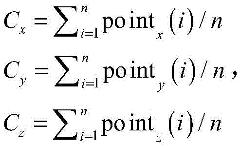
Cx为散点中心的x轴坐标;Cy为散点中心的y轴坐标;Cz为散点中心的z轴坐标;pointx(i)为映射到空间坐标系后第i个有限元顶点的x轴坐标;pointy(i)为映射到空间坐标系后第i个有限元顶点的y轴坐标;pointz(i)为映射到空间坐标系后第i个有限元顶点的z轴坐标;n为映射到空间坐标系后第i个有限元顶点的个数;∑为求和函数;C x is the x-axis coordinate of the scatter point center; C y is the y-axis coordinate of the scatter point center; C z is the z-axis coordinate of the scatter point center; point x (i) is the ith finite element after mapping to the space coordinate system The x-axis coordinate of the vertex; point y (i) is the y-axis coordinate of the i-th finite element vertex after being mapped to the space coordinate system; point z (i) is the z-axis of the i-th finite element vertex after being mapped to the space coordinate system Coordinates; n is the number of vertices of the ith finite element after being mapped to the space coordinate system; ∑ is a summation function;
将映射到空间坐标系后有限元顶点变换到矩阵中,并利用公式,A=U∑VT,进行矩阵奇异值分解,其中,Transform the vertices of the finite element into the matrix after being mapped to the space coordinate system, and use the formula, A=U∑V T , to perform matrix singular value decomposition, where,
A为将映射到空间坐标系后有限元顶点变换后得到的矩阵;U为左奇异向量;∑为求和函数;VT为右奇异向量;A is the matrix obtained after the finite element vertex transformation after mapping to the space coordinate system; U is the left singular vector; ∑ is the summation function; V T is the right singular vector;
根据VT获取参数第一参数、第二参数以及第三参数;Obtain the first parameter, the second parameter and the third parameter of the parameter according to V T ;
获取所述将映射到空间坐标系后有限元顶点变换后得到的矩阵中每一列的平均值作为一个元素,构建向量[Cx,Cy,Cz];Obtain the average value of each column in the matrix obtained after the finite element vertex transformation after mapping to the space coordinate system as an element, and construct a vector [C x , C y , C z ];
利用公式,d=-dot([a,b,c],[Cx,Cy,Cz]),计算第四参数的值,其中,Using the formula, d=-dot([a, b, c], [C x , C y , C z ]), calculate the value of the fourth parameter, where,
d为第四参数;dot为矩阵相乘函数;d is the fourth parameter; dot is the matrix multiplication function;
根据第一参数、第二参数、第三参数以及第四参数,获取拟合平面的一般式:ax+by+cz+d=0,其中,According to the first parameter, the second parameter, the third parameter and the fourth parameter, obtain the general formula of the fitting plane: ax+by+cz+d=0, where,
a为第一参数;x为横坐标;b为第二参数;y为纵坐标;c为第三参数;z为竖直坐标;d为第四参数。a is the first parameter; x is the abscissa; b is the second parameter; y is the ordinate; c is the third parameter; z is the vertical coordinate; d is the fourth parameter.
可选的,所述步骤4),包括:Optionally, the step 4) includes:
将所述外圆周轮廓线投影到拟合平面上,将拟合平面上由所述外圆周轮廓线围成的平面区域作为切面,或者,Projecting the contour line of the outer circumference onto a fitting plane, and using the plane area surrounded by the contour line of the outer circumference on the fitting plane as a tangent plane, or,
将所述外圆周轮廓线上的点投影到拟合平面上,将拟合平面上由所述外圆周轮廓线上的点围成的平面区域作为切面,其中,所述外圆周轮廓线上的点,包括:三维脊椎模型中椎弓根外圆周表面上的设定点。Project the points on the outer circumference contour line onto the fitting plane, and use the plane area surrounded by the points on the outer circumference contour line on the fitting plane as a tangent plane, wherein the points on the outer circumference contour line Points, including: set points on the outer circumferential surface of the pedicle in the three-dimensional spine model.
本发明实施例提供了一种三维脊椎模型中椎弓根的切面获取装置,所述装置包括:An embodiment of the present invention provides a device for obtaining section planes of pedicles in a three-dimensional spine model, the device comprising:
生成模块,用于基于三维医学图像处理技术,生成三维脊椎模型,其中,所述三维脊椎模型由若干个有限元组成;A generating module, configured to generate a three-dimensional spine model based on three-dimensional medical image processing technology, wherein the three-dimensional spine model is composed of several finite elements;
获取模块,用于获取所述三维脊椎模型中椎弓根的外圆周轮廓线;An acquisition module, configured to acquire the contour line of the outer circumference of the pedicle in the three-dimensional spine model;
将所述外圆周轮廓线经过的有限元的坐标映射到空间坐标系中,并根据映射后的有限元的空间坐标进行平面拟合,得到拟合平面;Mapping the coordinates of the finite elements through which the outline of the outer circumference passes into a space coordinate system, and performing plane fitting according to the space coordinates of the mapped finite elements to obtain a fitting plane;
切割模块,用于将所述拟合平面作为切割平面,切割所述三维脊椎模型得到切面。The cutting module is configured to use the fitting plane as a cutting plane, and cut the three-dimensional spine model to obtain a cutting plane.
可选的,所述获取模块,用于:Optionally, the acquiring module is used for:
获取所述三维脊椎模型中椎弓根外圆周表面上的设定点,将其中一个设定点作为当前设定点;Obtaining set points on the outer circumferential surface of the pedicle in the three-dimensional spine model, and using one of the set points as the current set point;
获取所述当前设定点的下一个设定点所对应的有限元中距离所述当前设定点最近的顶点,并将所述当前设定点到所述最近的顶点之间的连线作为所述当前设定点到所述最近的顶点之间的最短路径;Obtain the vertex closest to the current set point in the finite element corresponding to the next set point of the current set point, and use the connection line between the current set point and the nearest vertex as the shortest path between the current setpoint and the nearest vertex;
将所述当前设定点的下一个设定点作为当前设定点,并返回执行所述获取所述当前设定点的下一个设定点所对应的有限元中距离所述当前设定点最近的顶点的步骤,直至所述最短路径经过所有的设定点,将所有最短路径连接成为闭合轮廓作为外圆周轮廓线。Taking the next set point of the current set point as the current set point, and returning to the method of obtaining the next set point of the current set point corresponding to the finite element distance from the current set point In the step of the nearest vertex, until the shortest path passes through all the set points, all the shortest paths are connected into a closed contour as the outer circumference contour line.
可选的,所述最短路径是所述有限元的边界依次连接而成。Optionally, the shortest path is formed by sequentially connecting boundaries of the finite elements.
可选的,所述获取模块,用于:Optionally, the acquiring module is used for:
将所述外圆周轮廓线经过的有限元的顶点的坐标映射到空间坐标系中;Mapping the coordinates of the vertices of the finite elements that the contour line of the outer circumference passes through into a space coordinate system;
根据映射后的空间坐标,利用公式,
Cx为散点中心的x轴坐标;Cy为散点中心的y轴坐标;Cz为散点中心的z轴坐标;pointx(i)为映射到空间坐标系后第i个有限元顶点的x轴坐标;pointy(i)为映射到空间坐标系后第i个有限元顶点的y轴坐标;pointz(i)为映射到空间坐标系后第i个有限元顶点的z轴坐标;n为映射到空间坐标系后第i个有限元顶点的个数;∑为求和函数;C x is the x-axis coordinate of the scatter point center; C y is the y-axis coordinate of the scatter point center; C z is the z-axis coordinate of the scatter point center; point x (i) is the ith finite element after mapping to the space coordinate system The x-axis coordinate of the vertex; point y (i) is the y-axis coordinate of the i-th finite element vertex after being mapped to the space coordinate system; point z (i) is the z-axis of the i-th finite element vertex after being mapped to the space coordinate system Coordinates; n is the number of vertices of the ith finite element after being mapped to the space coordinate system; ∑ is a summation function;
将映射到空间坐标系后有限元顶点变换到矩阵中,并利用公式,A=U∑VT,进行矩阵奇异值分解,其中,Transform the vertices of the finite element into the matrix after being mapped to the space coordinate system, and use the formula, A=U∑V T , to perform matrix singular value decomposition, where,
A为将映射到空间坐标系后有限元顶点变换后得到的矩阵;U为左奇异向量;∑为求和函数;VT为右奇异向量;A is the matrix obtained after the finite element vertex transformation after mapping to the space coordinate system; U is the left singular vector; ∑ is the summation function; V T is the right singular vector;
根据VT获取参数第一参数、第二参数以及第三参数;Obtain the first parameter, the second parameter and the third parameter of the parameter according to V T ;
获取所述将映射到空间坐标系后有限元顶点变换后得到的矩阵中每一列的平均值作为一个元素,构建向量[Cx,Cy,Cz];Obtain the average value of each column in the matrix obtained after the finite element vertex transformation after mapping to the space coordinate system as an element, and construct a vector [C x , C y , C z ];
利用公式,d=-dot([a,b,c],[Cx,Cy,Cz]),计算第四参数的值,其中,Using the formula, d=-dot([a, b, c], [C x , C y , C z ]), calculate the value of the fourth parameter, where,
d为第四参数;dot为矩阵相乘函数;d is the fourth parameter; dot is the matrix multiplication function;
根据第一参数、第二参数、第三参数以及第四参数,获取拟合平面的一般式:ax+by+cz+d=0,其中,According to the first parameter, the second parameter, the third parameter and the fourth parameter, obtain the general formula of the fitting plane: ax+by+cz+d=0, where,
a为第一参数;x为横坐标;b为第二参数;y为纵坐标;c为第三参数;z为竖直坐标;d为第四参数。a is the first parameter; x is the abscissa; b is the second parameter; y is the ordinate; c is the third parameter; z is the vertical coordinate; d is the fourth parameter.
可选的,所述切割模块,用于:Optionally, the cutting module is used for:
将所述外圆周轮廓线投影到拟合平面上,将拟合平面上由所述外圆周轮廓线围成的平面区域作为切面,或者,Projecting the contour line of the outer circumference onto a fitting plane, and using the plane area surrounded by the contour line of the outer circumference on the fitting plane as a tangent plane, or,
将所述外圆周轮廓线上的点投影到拟合平面上,将拟合平面上由所述外圆周轮廓线上的点围成的平面区域作为切面,其中,所述外圆周轮廓线上的点,包括:三维脊椎模型中椎弓根外圆周表面上的设定点。Project the points on the outer circumference contour line onto the fitting plane, and use the plane area surrounded by the points on the outer circumference contour line on the fitting plane as a tangent plane, wherein the points on the outer circumference contour line Points, including: set points on the outer circumferential surface of the pedicle in the three-dimensional spine model.
本发明相比现有技术具有以下优点:Compared with the prior art, the present invention has the following advantages:
应用本发明实施例,基于三维医学图像处理技术,生成三维脊椎模型,利用三维几何造型技术对三维模型进行可视化操作,识别出椎弓根所在的截面,可以为模拟手术植入螺钉过程提供参照,完善了功能,解决了现有技术中功能较为单一的技术问题。Applying the embodiment of the present invention, based on the 3D medical image processing technology, a 3D spine model is generated, and the 3D model is visualized using the 3D geometric modeling technology to identify the section where the pedicle is located, which can provide a reference for simulating the surgical implantation of screws. The function is improved, and the technical problem of relatively single function in the prior art is solved.
附图说明Description of drawings
图1为本发明实施例提供的一种三维脊椎模型中椎弓根的切面获取方法的流程示意图;Fig. 1 is a schematic flow chart of a method for obtaining a cut plane of a pedicle in a three-dimensional spine model provided by an embodiment of the present invention;
图2为本发明实施例提供的一种三维脊椎模型中椎弓根的切面获取方法的原理示意图;FIG. 2 is a schematic diagram of the principle of a method for obtaining a cut surface of a pedicle in a three-dimensional spine model provided by an embodiment of the present invention;
图3为本发明实施例提供的一种三维脊椎模型中椎弓根的切面获取方法中两个设定点之间的最短路径的示意图;Fig. 3 is a schematic diagram of the shortest path between two set points in a method for obtaining a cut plane of a pedicle in a three-dimensional spine model provided by an embodiment of the present invention;
图4为本发明实施例提供的一种三维脊椎模型中椎弓根的切面获取方法中两个设定点之间的最短路径的经过的三角片的渲染示意图;Fig. 4 is a rendering schematic diagram of a triangular slice passing through the shortest path between two set points in a method for obtaining a cut plane of the pedicle in a three-dimensional spine model provided by an embodiment of the present invention;
图5为本发明实施例提供的一种三维脊椎模型中椎弓根的切面获取方法中拟合平面示意图;FIG. 5 is a schematic diagram of a fitting plane in a method for obtaining a cut plane of a pedicle in a three-dimensional spine model provided by an embodiment of the present invention;
图6为本发明实施例提供的一种三维脊椎模型中椎弓根的切面获取方法中设定点在拟合平面上投影示意图;Fig. 6 is a schematic diagram of projection of set points on a fitting plane in a method for obtaining a cut plane of a pedicle in a three-dimensional spine model provided by an embodiment of the present invention;
图7为本发明实施例提供的一种三维脊椎模型中椎弓根的切面获取方法中切面示意图;Fig. 7 is a schematic view of the section in the method for obtaining the section of the pedicle in the three-dimensional spine model provided by the embodiment of the present invention;
图8为本发明实施例提供的一种三维脊椎模型中椎弓根的切面获取装置的结构示意图。Fig. 8 is a schematic structural diagram of a device for acquiring a section plane of a pedicle in a three-dimensional vertebral model provided by an embodiment of the present invention.
具体实施方式Detailed ways
下面对本发明的实施例作详细说明,本实施例在以本发明技术方案为前提下进行实施,给出了详细的实施方式和具体的操作过程,但本发明的保护范围不限于下述的实施例。The embodiments of the present invention are described in detail below. This embodiment is implemented on the premise of the technical solution of the present invention, and detailed implementation methods and specific operating procedures are provided, but the protection scope of the present invention is not limited to the following implementation example.
本发明实施例提供了一种三维脊椎模型中椎弓根的切面获取方法及装置,下面首先就本发明实施例提供的一种三维脊椎模型中椎弓根的切面获取方法进行介绍。Embodiments of the present invention provide a method and device for obtaining a section plane of a pedicle in a three-dimensional spine model. The method for obtaining a section plane of a pedicle in a three-dimensional spine model provided by the embodiment of the present invention is firstly introduced below.
图1为本发明实施例提供的一种三维脊椎模型中椎弓根的切面获取方法的流程示意图,图2为本发明实施例提供的一种三维脊椎模型中椎弓根的切面获取方法的原理示意图;如图1和图2所示,所述方法包括:Fig. 1 is a schematic flowchart of a method for obtaining a cut plane of a pedicle in a three-dimensional spine model provided by an embodiment of the present invention, and Fig. 2 is a principle of a method for obtaining a cut plane of a pedicle in a three-dimensional spine model provided by an embodiment of the present invention Schematic diagram; As shown in Fig. 1 and Fig. 2, described method comprises:
S101:基于三维医学图像处理技术,生成三维脊椎模型,其中,所述三维脊椎模型由若干个有限元组成。S101: Generate a three-dimensional spine model based on a three-dimensional medical image processing technology, wherein the three-dimensional spine model is composed of several finite elements.
在实际应用中,可以使用Solidworks、CATIA、ANSYS等软件进行脊椎的三维建模。可以理解的是,三维模型的表面是由许多小平面,如三角形、矩形拼接而成的。In practical applications, software such as Solidworks, CATIA, and ANSYS can be used for three-dimensional modeling of the spine. It can be understood that the surface of the 3D model is composed of many small planes, such as triangles and rectangles.
S102:获取所述三维脊椎模型中椎弓根的外圆周轮廓线。S102: Obtain the outline of the outer circumference of the pedicle in the three-dimensional spine model.
具体的,可以获取所述三维脊椎模型中椎弓根外圆周表面上的设定点,将其中一个设定点作为当前设定点;Specifically, the set points on the outer circumferential surface of the pedicle in the three-dimensional spine model can be obtained, and one of the set points can be used as the current set point;
获取所述当前设定点的下一个设定点所对应的有限元中距离所述当前设定点最近的顶点,并将所述当前设定点到所述最近的顶点之间的连线作为所述当前设定点到所述最近的顶点之间的最短路径;所述最短路径是所述有限元的边界依次连接而成。Obtain the vertex closest to the current set point in the finite element corresponding to the next set point of the current set point, and use the connection line between the current set point and the nearest vertex as The shortest path between the current set point and the nearest vertex; the shortest path is formed by sequentially connecting the boundaries of the finite elements.
将所述当前设定点的下一个设定点作为当前设定点,并返回执行所述获取所述当前设定点的下一个设定点所对应的有限元中距离所述当前设定点最近的顶点的步骤,直至所述最短路径经过所有的设定点,将所有最短路径连接成为闭合轮廓作为外圆周轮廓线。Taking the next set point of the current set point as the current set point, and returning to the method of obtaining the next set point of the current set point corresponding to the finite element distance from the current set point In the step of the nearest vertex, until the shortest path passes through all the set points, all the shortest paths are connected into a closed contour as the outer circumference contour line.
在实际应用中,可以首先在模型椎弓根表面外围通过鼠标点击选择表面附着点,即设定点1,由于椎骨表面模型是由许多三角片组成,因此,设定点1对应的三角片为三角片1。In practical applications, the surface attachment point can be selected by clicking the mouse on the periphery of the pedicle surface of the model, that is, set point 1. Since the vertebral surface model is composed of many triangular slices, the triangle slice corresponding to set point 1 is triangle piece1.
从三角片1的所有相邻的三角片的各个顶点中选择出距离设定点1的下一个设定点,即设定点2的距离最近的顶点作为P1,并将此顶点P1放入到椎弓根轮廓点链表contourPointList合中。From each vertex of all adjacent triangles of triangle 1, select the next set point from set point 1, that is, the nearest vertex of set point 2 as P1, and put this vertex P1 into The pedicle contour point linked list contourPointList is centered.
接下来进入循环,从链表contourPointList中最新加入的P1点开始,首先找到与P1相邻的其它三角片的各个顶点,并在这些顶点中寻找一个距离设定点2最近的一个顶点P2,并将P2也放入链表contourPointList中。Then enter the loop, starting from the newly added point P1 in the linked list contourPointList, first find the vertices of other triangles adjacent to P1, and find a vertex P2 closest to the set point 2 among these vertices, and set P2 is also put into the linked list contourPointList.
图3为本发明实施例提供的一种三维脊椎模型中椎弓根的切面获取方法中两个设定点之间的最短路径的示意图,如图3所示,链表contourPointList中各个顶点之间的连线即为最短路径。Fig. 3 is a schematic diagram of the shortest path between two set points in the pedicle cut plane acquisition method in a three-dimensional spine model provided by an embodiment of the present invention, as shown in Fig. The link is the shortest path.
按照此步骤依次循环,直到循环到离最后一个设定点为止。Follow this step to cycle in sequence until the cycle reaches the last set point.
经过上述步骤,就能够通过用户交互,得到椎骨模型中椎弓根外围的轮廓上经过的点,通过将这些点连接成线,最后得到椎弓根的轮廓线。After the above steps, the points passed on the contour of the pedicle periphery in the vertebral model can be obtained through user interaction, and by connecting these points into a line, the contour line of the pedicle can be finally obtained.
在得到最短路径之后,首先要将路径经过的三角片的序号分别加入到selectCellIdSet这个变量中。接下来的第一步,要利用selectCellIdSet中存储的三角片的ID(Identification,识别信息),来将这些三角片进行渲染突出显示。After obtaining the shortest path, first add the sequence numbers of the triangles that the path passes through to the variable selectCellIdSet. The next first step is to use the ID (Identification, identification information) of the triangles stored in the selectCellIdSet to render and highlight these triangles.
然后使用得到的椎弓根轮廓线经过的模型表面点的链表contourPointList,从其中第一个点P1开始进入循环,每次从整块椎骨数据中,查找以P1为顶点的三角片的编号ID,并将ID放入selectCellIdSet集合中,在此过程中需要把重复的ID进行过滤。Then use the linked list contourPointList of the model surface points that the obtained pedicle contour line passes through, enter the loop from the first point P1, and search for the number ID of the triangle with P1 as the vertex from the entire vertebral data each time. And put the ID into the selectCellIdSet collection, and need to filter the duplicate ID in the process.
循环结束后,得到了所有椎弓根轮廓线经过的模型表面三角片的编号ID,接下来进入另一个循环,将selectCellIdSet中的每一个三角片进行高亮显示,给用户以直观的显示效果。图4为本发明实施例提供的一种三维脊椎模型中椎弓根的切面获取方法中两个设定点之间的最短路径的经过的三角片的渲染示意图。After the loop ends, the number IDs of the triangles on the model surface that all the pedicle contour lines pass through are obtained, and then another loop is entered to highlight each triangle in the selectCellIdSet to give the user an intuitive display effect. Fig. 4 is a schematic rendering diagram of a triangular piece passing through the shortest path between two set points in a method for obtaining a section plane of a pedicle in a three-dimensional spine model according to an embodiment of the present invention.
S103:将所述外圆周轮廓线经过的有限元的坐标映射到空间坐标系中,并根据映射后的有限元的空间坐标进行平面拟合,得到拟合平面。S103: Map the coordinates of the finite elements through which the outline of the outer circumference passes to a space coordinate system, and perform plane fitting according to the mapped space coordinates of the finite elements to obtain a fitting plane.
具体的,将所述外圆周轮廓线经过的有限元的顶点的坐标映射到空间坐标系中。Specifically, the coordinates of the vertices of the finite elements through which the outer circumference contour line passes are mapped into a space coordinate system.
可以将去重后的有限元顶点坐标,即链表contourPointList中的顶点坐标映射到空间坐标系中。The deduplicated finite element vertex coordinates, that is, the vertex coordinates in the linked list contourPointList can be mapped to the space coordinate system.
根据映射后的空间坐标,利用公式,
Cx为散点中心的x轴坐标;Cy为散点中心的y轴坐标;Cz为散点中心的z轴坐标;pointx(i)为映射到空间坐标系后第i个有限元顶点的x轴坐标;pointy(i)为映射到空间坐标系后第i个有限元顶点的y轴坐标;pointz(i)为映射到空间坐标系后第i个有限元顶点的z轴坐标;n为映射到空间坐标系后第i个有限元顶点的个数;∑为求和函数;C x is the x-axis coordinate of the scatter point center; C y is the y-axis coordinate of the scatter point center; C z is the z-axis coordinate of the scatter point center; point x (i) is the ith finite element after mapping to the space coordinate system The x-axis coordinate of the vertex; point y (i) is the y-axis coordinate of the i-th finite element vertex after being mapped to the space coordinate system; point z (i) is the z-axis of the i-th finite element vertex after being mapped to the space coordinate system Coordinates; n is the number of vertices of the ith finite element after being mapped to the space coordinate system; ∑ is a summation function;
将映射到空间坐标系后有限元顶点变换到矩阵中,将所有中心点进行变换得到一个n*3的矩阵A。可以利用公式,A=U∑VT,进行矩阵奇异值分解,其中,After mapping to the space coordinate system, the vertices of the finite element are transformed into a matrix, and all center points are transformed to obtain a matrix A of n*3. The formula, A=U∑V T , can be used to perform matrix singular value decomposition, where,
A为将映射到空间坐标系后有限元顶点变换后得到的矩阵,为输入矩阵,大小为n*3;U为左奇异向量,为一个n*n的矩阵;A为一个n*3的对角阵;VT为右奇异向量,为一个3*3的矩阵;A is the matrix obtained by transforming the finite element vertices after mapping to the space coordinate system, which is the input matrix with a size of n*3; U is the left singular vector, which is a matrix of n*n; A is a pair of n*3 Angular matrix; V T is the right singular vector, which is a 3*3 matrix;
因为空间平面的一般式为ax+by+cz+d=0,利用矩阵奇异值分解,得到a,b,c,d四个值,其中a,b,c三个值就是最终要得到的normalVec(法向量)向量。Because the general formula of the space plane is ax+by+cz+d=0, using the singular value decomposition of the matrix, four values of a, b, c, and d are obtained, among which the three values of a, b, and c are the final normalVec to be obtained (normal vector) vector.
根据VT获取参数第一参数、第二参数以及第三参数;Obtain the first parameter, the second parameter and the third parameter of the parameter according to V T ;
获取所述将映射到空间坐标系后有限元顶点变换后得到的矩阵中每一列的平均值作为一个元素,构建向量[Cx,Cy,Cz];Obtain the average value of each column in the matrix obtained after the finite element vertex transformation after mapping to the space coordinate system as an element, and construct a vector [C x , C y , C z ];
利用公式,d=-dot([a,b,c],[Cx,Cy,Cz]),计算第四参数的值,其中,Using the formula, d=-dot([a, b, c], [C x , C y , C z ]), calculate the value of the fourth parameter, where,
d为第四参数;dot为矩阵相乘函数;d is the fourth parameter; dot is the matrix multiplication function;
根据第一参数、第二参数、第三参数以及第四参数,获取拟合平面的一般式:ax+by+cz+d=0,其中,According to the first parameter, the second parameter, the third parameter and the fourth parameter, obtain the general formula of the fitting plane: ax+by+cz+d=0, where,
a为第一参数;x为横坐标;b为第二参数;y为纵坐标;c为第三参数;z为竖直坐标;d为第四参数。a is the first parameter; x is the abscissa; b is the second parameter; y is the ordinate; c is the third parameter; z is the vertical coordinate; d is the fourth parameter.
在实际应用中,可以首先根据S102步骤中得到的selectCellIdSet三角片ID集合,依次得到每个三角片上的顶点数据,存入到CellPoints集合中,计算的过程中可以过滤掉重复的点。In practical applications, firstly, according to the selectCellIdSet triangular piece ID set obtained in step S102, the vertex data on each triangular piece can be sequentially obtained, and stored in the CellPoints set, and repeated points can be filtered out during the calculation process.
然后利用集合CellPoints,根据公式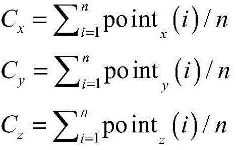
得到中心点之后,下一步的操作是继续利用点集CellPoints,将其转化成一个n*3大小的矩阵A,其中每一行代表一个点的xyz坐标轴上的坐标,以A作为输入矩阵进行矩阵奇异值分解。计算后得到VT中代表拟合平面法向量的那个列向量,分别赋于a,b,c三个值,然后利用A矩阵中每一列的平均值作为一个向量,也就是前述中的[Cx,Cy,Cz]。After getting the center point, the next step is to continue to use the point set CellPoints to convert it into a matrix A of n*3 size, where each row represents the coordinates on the xyz coordinate axis of a point, and use A as the input matrix to perform matrix Singular value decomposition. After calculation, the column vector representing the fitting plane normal vector in V T is obtained, respectively assigned to three values of a, b, and c, and then the average value of each column in the A matrix is used as a vector, that is, [C x , C y , C z ].
然后,利用公式,d=-dot([a,b,c],[Cx,Cy,Cz]),得到平面一般式的最后一个d的值。Then, using the formula, d=-dot([a, b, c], [C x , C y , C z ]), the value of the last d in the general formula of the plane is obtained.
此时,得到了能够唯一确定一个平面的中心点和法向量以及平面的一般式ax+by+cz+d=0。At this time, the general formula ax+by+cz+d=0 that can uniquely determine the center point and normal vector of a plane and the plane is obtained.
图5为本发明实施例提供的一种三维脊椎模型中椎弓根的切面获取方法中拟合平面示意图,如图5所示,图5中的点为设定点,其为空间中的离散点。Fig. 5 is a schematic diagram of a fitting plane in a method for obtaining a cut plane of a pedicle in a three-dimensional spine model provided by an embodiment of the present invention. As shown in Fig. 5, the points in Fig. 5 are set points, which are discrete points in space. point.
在实际应用中,利用奇异值分解获取第一参数、第二参数、第三参数以及第四参数的过程为:In practical applications, the process of using singular value decomposition to obtain the first parameter, the second parameter, the third parameter and the fourth parameter is:
例如,已知若干三维点坐标(xi,yi,zi),拟合的平面方程为:For example, if several 3D point coordinates ( xi , y, zi ) are known, the fitted plane equation is:
ax+by+cz=d (1),其中,该公式的约束条件为:a2+b2+c2=1 (2),以使使得该平面到所有的三维点的距离之和最小,其中,ax+by+cz=d (1), wherein, the constraint condition of this formula is: a 2 +b 2 +c 2 =1 (2), so that the sum of the distances from the plane to all three-dimensional points is minimum, in,
a为第一参数;b为第二参数;y为纵坐标;c为第三参数;z为竖直坐标;d为第四参数;i为三维坐标点的序号。a is the first parameter; b is the second parameter; y is the vertical coordinate; c is the third parameter; z is the vertical coordinate; d is the fourth parameter; i is the serial number of the three-dimensional coordinate point.
如果所有点的平均坐标为
式(1)与式(3)相减,得
令矩阵A为: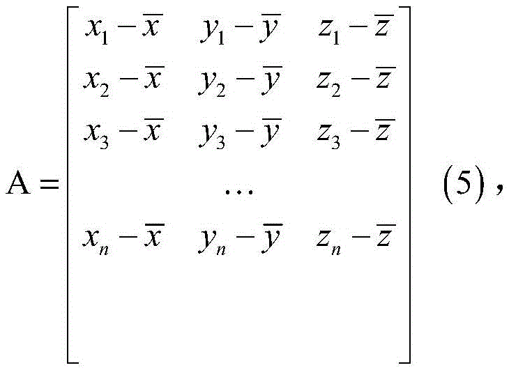
矩阵X为: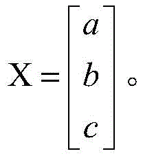
则有:Then there are:
则式(4)等价于AX=0。Then formula (4) is equivalent to AX=0.
在理想情况下所有的三维点都在所拟合得到的平面上,则式(5)成立,实际情况下有部分点在平面外,拟合的目的为所有点刀平面的距离之和尽量小,所以可以设目标函数为minAX (6),约束条件为X=1 (7)。.Ideally, all three-dimensional points are on the fitted plane, then Equation (5) holds true. In reality, some points are outside the plane. The purpose of fitting is to minimize the sum of the distances between all point-knife planes , so the objective function can be set as minAX (6), and the constraint condition is X=1 (7). .
若A可做奇异值分解:A=UΣVT (8),其中,If A can be subjected to singular value decomposition: A=UΣV T (8), where,
Σ为对角矩阵;U为左奇异矩阵;V为右奇异矩阵,左奇异和右奇异矩阵均为酉矩阵。Σ is a diagonal matrix; U is a left singular matrix; V is a right singular matrix, and both left and right singular matrices are unitary matrices.
则有:
VTX为列矩阵,并且VTX=X=1 (10)V T X is a column matrix, and V T X = X = 1 (10)
因为Σ的对角元素为奇异值,如果最后一个对角元素为最小奇异值,则当且仅当
此时
v1为右奇异矩阵V中第一个列向量;v2为右奇异矩阵V中第二个列向量;vn为右奇异矩阵V中最后一个列向量。v 1 is the first column vector in the right singular matrix V; v 2 is the second column vector in the right singular matrix V; v n is the last column vector in the right singular matrix V.
所以,目标函数(6)在约束条件(7)下的最优解为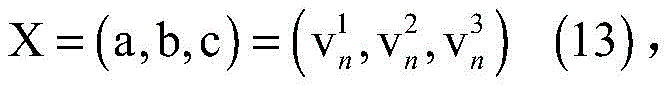
即X,也就是vn为右奇异矩阵VT中,对应Σ中最小奇异值的那一个列向量。That is, X, that is, v n is the column vector corresponding to the smallest singular value in Σ in the right singular matrix V T.
综上:对矩阵A做奇异值分解,最小奇异值对应的特征向量就是拟合平面的系数向量。To sum up: Singular value decomposition is performed on the matrix A, and the eigenvector corresponding to the smallest singular value is the coefficient vector of the fitting plane.
在实际应用中,可以利用opencv中的cvSVD()函数对所有点构成的n*3的矩阵进行奇异值分解,得到的结果Σ中的奇异值是按照从上往下,从大到小的顺序自动排列的,所以我们将得到的转置向量VT中的最后一个1*3的行向量或者V向量中的列向量,作为拟合平面的法向量normalVec,分别赋给a,b,c三个值,d的值根据所有中心点代入方程式即可求出。In practical applications, you can use the cvSVD() function in opencv to perform singular value decomposition on the n*3 matrix composed of all points, and the singular values in the result Σ are in the order from top to bottom and from large to small It is automatically arranged, so we will get the last 1*3 row vector in the transposed vector V T or the column vector in the V vector as the normal vector normalVec of the fitting plane, and assign them to a, b, and c respectively value, the value of d can be obtained by substituting all center points into the equation.
S104:将所述拟合平面作为切割平面,切割所述三维脊椎模型得到切面。S104: Using the fitting plane as a cutting plane, cutting the three-dimensional spine model to obtain a cutting plane.
具体的,将所述外圆周轮廓线投影到拟合平面上,将拟合平面上由所述外圆周轮廓线围成的平面区域作为切面。Specifically, the outer circumference contour line is projected onto a fitting plane, and the plane area surrounded by the outer circumference contour line on the fitting plane is used as a tangent plane.
得到拟合的平面之后,就可以利用此平面作为切割面,来切割椎骨模型获取切面轮廓,但是这样实现会出现一个问题:无法界定切割平面的大小。这样就很容易切到椎骨的其他部分,影响观察。After the fitted plane is obtained, this plane can be used as a cutting plane to cut the vertebral model to obtain the contour of the cutting plane, but there will be a problem in this implementation: the size of the cutting plane cannot be defined. In this way, it is easy to cut to other parts of the vertebrae and affect the observation.
这里我们的解决方案是:利用最开始自动寻找的一圈轮廓线上的空间点,来将这些点投影到切割平面上,这样的话就能够得到局部切割椎弓根的效果。Our solution here is: use the spatial points on the contour line that were automatically found at the beginning to project these points onto the cutting plane, so that the effect of partial cutting of the pedicle can be obtained.
下面,对本发明优选的实施例进行进一步介绍:Below, the preferred embodiment of the present invention is further introduced:
将所述外圆周轮廓线上的点投影到拟合平面上,将拟合平面上由所述外圆周轮廓线上的点围成的平面区域作为切面,其中,所述外圆周轮廓线上的点,包括:三维脊椎模型中椎弓根外圆周表面上的设定点。图6为本发明实施例提供的一种三维脊椎模型中椎弓根的切面获取方法中设定点在拟合平面上投影示意图;如图5所示,设定点在拟合平面上的投影点所包围的区域为切割平面。图6中的空心圆圈为图5中的拟合平面对应的点集中的点。Project the points on the outer circumference contour line onto the fitting plane, and use the plane area surrounded by the points on the outer circumference contour line on the fitting plane as a tangent plane, wherein the points on the outer circumference contour line Points, including: set points on the outer circumferential surface of the pedicle in the three-dimensional spine model. Fig. 6 is a schematic diagram of the projection of the set point on the fitting plane in a method for obtaining the cut plane of the pedicle in a three-dimensional spine model provided by an embodiment of the present invention; as shown in Fig. 5 , the projection of the set point on the fitting plane The area enclosed by the points is the cutting plane. The hollow circles in FIG. 6 are the points in the set of points corresponding to the fitting plane in FIG. 5 .
后期进行螺钉模拟植入的操作时,因为螺钉模型和椎骨模型不属于同一个模型,所以可以只利用拟合平面切割螺钉模型得到轮廓,和椎弓根投影轮廓组合便能够实现椎弓根部分的切面效果。When the screw simulation implantation operation is performed later, because the screw model and the vertebral model do not belong to the same model, the contour of the pedicle part can be realized by only using the fitted plane cutting screw model, and combining with the pedicle projection contour. Cutting effect.
在实际应用中,首先利用CellPoints集合中的所有散点的坐标值,计算每个散点投影到拟合平面上的投影点,计算投影点的步骤如下:In practical applications, first use the coordinate values of all the scattered points in the CellPoints collection to calculate the projection point of each scattered point projected onto the fitting plane. The steps for calculating the projected point are as follows:
假设其中一个设定点的坐标为Vi,(xi,yi,zi),其在拟合平面上的投影点坐标为V,(x,y,z),则直线ViV与拟合平面的法向量平行,其参数方程设为:Assuming that the coordinates of one of the set points are Vi, ( xi , y i , zi ), and the coordinates of its projected point on the fitting plane are V, (x, y, z), then the straight line ViV and the fitting plane The normal vectors of are parallel, and its parameter equation is set as:
x=xi-atx= xi -at
y=yi-bt。y=y i −bt.
z=zi-ctz=z i -ct
将上述公式代入平面方程,计算出t的大小如下:Substituting the above formula into the plane equation, the size of t is calculated as follows:
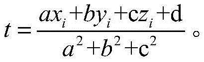
最后将t代回直线ViV的参数方程,得到最终的投影点V。Finally, substitute t back into the parametric equation of the straight line ViV to obtain the final projected point V.
其他设定点也按照上述方法进行处理,得到各个设定点的投影点集ProjectPoints。Other set points are also processed according to the above method to obtain the projected point set ProjectPoints of each set point.
然后,按照顺序依次连接每两点得到最终的椎弓根轮廓线,并利用拟合平面的中心点和法向量设置一个切面。效果如图6所示,图6为本发明实施例提供的一种三维脊椎模型中椎弓根的切面获取方法中设定点在拟合平面上投影示意图。Then, connect every two points sequentially to obtain the final pedicle contour line, and use the center point and normal vector of the fitting plane to set a cut plane. The effect is shown in FIG. 6 , which is a schematic diagram of the projection of the set point on the fitting plane in a method for obtaining a cut plane of the pedicle in the three-dimensional spine model provided by the embodiment of the present invention.
若存在螺钉数据,则切割螺钉数据得到螺钉在此平面上的切面轮廓,将其与椎弓根轮廓一同显示到界面,供用户在螺钉模拟植入的过程中参考。效果如图7所示,图7为本发明实施例提供的一种三维脊椎模型中椎弓根的切面获取方法中切面示意图;在图7中,圆圈701和圆圈702为螺钉的切面,椭圆703和椭圆704为脊椎的椎弓根的切面。If there is screw data, cut the screw data to obtain the profile of the screw section on this plane, and display it on the interface together with the pedicle profile for the user's reference during the screw simulation implantation process. The effect is shown in Figure 7, which is a schematic view of the section in the method for obtaining the section of the pedicle in a three-dimensional spine model provided by the embodiment of the present invention; in Figure 7, the
应用本发明图1所示实施例,基于三维医学图像处理技术,生成三维脊椎模型,利用三维几何造型技术对三维模型进行可视化操作,识别出椎弓根所在的截面,可以为模拟手术植入螺钉过程提供参照,完善了功能,解决了现有技术中功能较为单一的技术问题。Apply the embodiment shown in Figure 1 of the present invention, based on the 3D medical image processing technology, generate a 3D spine model, use 3D geometric modeling technology to visualize the 3D model, identify the section where the pedicle is located, and implant screws for simulated surgery The process provides a reference, improves the function, and solves the technical problem of relatively single function in the prior art.
另外,本发明实施例中,利用三维建模技术重建的患者的脊柱三维模型,并对三维模型进行直观交互式地操作,实现了在模型上进行模拟椎弓根螺钉植入时,在椎弓根部分进行轮廓参照的效果,防止螺钉打偏损害椎弓根。本发明能够应用于临床手术,作为椎弓根部分植入螺钉的参照,也能够应用于教学方面。与目前大多数医生只能通过自身经验判断螺钉植入情况相比,本发明能够提高手术安全系数,并且在教学方面,比直接利用二维切片图教学更加直观和生动。In addition, in the embodiment of the present invention, the three-dimensional model of the patient's spine is reconstructed using three-dimensional modeling technology, and the three-dimensional model is intuitively and interactively operated, so that when the pedicle screw is implanted on the model, the The effect of contour reference on the root part prevents screw deviation from damaging the pedicle. The invention can be applied to clinical operations, as a reference for implanting screws in the pedicle part, and can also be applied to teaching. Compared with the current situation where most doctors can only judge screw implantation based on their own experience, the present invention can improve the operation safety factor, and in terms of teaching, it is more intuitive and vivid than directly using two-dimensional slice diagrams for teaching.
与本发明图1所示实施例相对应,本发明实施例还提供了一种三维脊椎模型中椎弓根的切面获取装置。Corresponding to the embodiment shown in FIG. 1 of the present invention, the embodiment of the present invention also provides a device for obtaining a cut plane of a pedicle in a three-dimensional vertebra model.
图8为本发明实施例提供的一种三维脊椎模型中椎弓根的切面获取装置的结构示意图,如图8所示,所述装置包括:Fig. 8 is a schematic structural diagram of a device for acquiring a cut surface of a pedicle in a three-dimensional spine model provided by an embodiment of the present invention. As shown in Fig. 8, the device includes:
生成模块801,用于基于三维医学图像处理技术,生成三维脊椎模型,其中,所述三维脊椎模型由若干个有限元组成;A
获取模块802,用于获取所述三维脊椎模型中椎弓根的外圆周轮廓线;An
将所述外圆周轮廓线经过的有限元的坐标映射到空间坐标系中,并根据映射后的有限元的空间坐标进行平面拟合,得到拟合平面;Mapping the coordinates of the finite elements through which the outline of the outer circumference passes into a space coordinate system, and performing plane fitting according to the space coordinates of the mapped finite elements to obtain a fitting plane;
切割模块803,用于将所述拟合平面作为切割平面,切割所述三维脊椎模型得到切面。The
应用本发明图8所示实施例,基于三维医学图像处理技术,生成三维脊椎模型,利用三维几何造型技术对三维模型进行可视化操作,识别出椎弓根所在的截面,可以为模拟手术植入螺钉过程提供参照,完善了功能,解决了现有技术中功能较为单一的技术问题。Applying the embodiment shown in Figure 8 of the present invention, based on the 3D medical image processing technology, a 3D spine model is generated, and the 3D model is visualized using the 3D geometric modeling technology, and the section where the pedicle is identified can be implanted with screws for simulated surgery. The process provides a reference, improves the function, and solves the technical problem of relatively single function in the prior art.
在本发明实施例的一种具体实施方式中,所述获取模块802,用于:In a specific implementation manner of the embodiment of the present invention, the
获取所述三维脊椎模型中椎弓根外圆周表面上的设定点,将其中一个设定点作为当前设定点;Obtaining set points on the outer circumferential surface of the pedicle in the three-dimensional spine model, and using one of the set points as the current set point;
获取所述当前设定点的下一个设定点所对应的有限元中距离所述当前设定点最近的顶点,并将所述当前设定点到所述最近的顶点之间的连线作为所述当前设定点到所述最近的顶点之间的最短路径;Obtain the vertex closest to the current set point in the finite element corresponding to the next set point of the current set point, and use the connection line between the current set point and the nearest vertex as the shortest path between the current setpoint and the nearest vertex;
将所述当前设定点的下一个设定点作为当前设定点,并返回执行所述获取所述当前设定点的下一个设定点所对应的有限元中距离所述当前设定点最近的顶点的步骤,直至所述最短路径经过所有的设定点,将所有最短路径连接成为闭合轮廓作为外圆周轮廓线。Taking the next set point of the current set point as the current set point, and returning to the method of obtaining the next set point of the current set point corresponding to the finite element distance from the current set point In the step of the nearest vertex, until the shortest path passes through all the set points, all the shortest paths are connected into a closed contour as the outer circumference contour line.
在本发明实施例的一种具体实施方式中,所述最短路径是所述有限元的边界依次连接而成。In a specific implementation manner of the embodiment of the present invention, the shortest path is formed by sequentially connecting boundaries of the finite elements.
在本发明实施例的一种具体实施方式中,所述获取模块802,用于:In a specific implementation manner of the embodiment of the present invention, the
将所述外圆周轮廓线经过的有限元的顶点的坐标映射到空间坐标系中;Mapping the coordinates of the vertices of the finite elements that the contour line of the outer circumference passes through into a space coordinate system;
根据映射后的空间坐标,利用公式,
Cx为散点中心的x轴坐标;Cy为散点中心的y轴坐标;Cz为散点中心的z轴坐标;pointx(i)为映射到空间坐标系后第i个有限元顶点的x轴坐标;pointy(i)为映射到空间坐标系后第i个有限元顶点的y轴坐标;pointz(i)为映射到空间坐标系后第i个有限元顶点的z轴坐标;n为映射到空间坐标系后第i个有限元顶点的个数;∑为求和函数;C x is the x-axis coordinate of the scatter point center; C y is the y-axis coordinate of the scatter point center; C z is the z-axis coordinate of the scatter point center; point x (i) is the ith finite element after mapping to the space coordinate system The x-axis coordinate of the vertex; point y (i) is the y-axis coordinate of the i-th finite element vertex after being mapped to the space coordinate system; point z (i) is the z-axis of the i-th finite element vertex after being mapped to the space coordinate system Coordinates; n is the number of vertices of the ith finite element after being mapped to the space coordinate system; ∑ is a summation function;
将映射到空间坐标系后有限元顶点变换到矩阵中,并利用公式,A=U∑VT,进行矩阵奇异值分解,其中,Transform the vertices of the finite element into the matrix after being mapped to the space coordinate system, and use the formula, A=U∑V T , to perform matrix singular value decomposition, where,
A为将映射到空间坐标系后有限元顶点变换后得到的矩阵;U为左奇异向量;∑为求和函数;VT为右奇异向量;A is the matrix obtained after the finite element vertex transformation after mapping to the space coordinate system; U is the left singular vector; ∑ is the summation function; V T is the right singular vector;
根据VT获取参数第一参数、第二参数以及第三参数;Obtain the first parameter, the second parameter and the third parameter of the parameter according to V T ;
获取所述将映射到空间坐标系后有限元顶点变换后得到的矩阵中每一列的平均值作为一个元素,构建向量[Cx,Cy,Cz];Obtain the average value of each column in the matrix obtained after the finite element vertex transformation after mapping to the space coordinate system as an element, and construct a vector [C x , C y , C z ];
利用公式,d=-dot([a,b,c],[Cx,Cy,Cz]),计算第四参数的值,其中,Using the formula, d=-dot([a, b, c], [C x , C y , C z ]), calculate the value of the fourth parameter, where,
d为第四参数;dot为矩阵相乘函数;d is the fourth parameter; dot is the matrix multiplication function;
根据第一参数、第二参数、第三参数以及第四参数,获取拟合平面的一般式:ax+by+cz+d=0,其中,According to the first parameter, the second parameter, the third parameter and the fourth parameter, obtain the general formula of the fitting plane: ax+by+cz+d=0, where,
a为第一参数;x为横坐标;b为第二参数;y为纵坐标;c为第三参数;z为竖直坐标;d为第四参数。a is the first parameter; x is the abscissa; b is the second parameter; y is the ordinate; c is the third parameter; z is the vertical coordinate; d is the fourth parameter.
在本发明实施例的一种具体实施方式中,所述切割模块803,用于:In a specific implementation manner of the embodiment of the present invention, the
将所述外圆周轮廓线投影到拟合平面上,将拟合平面上由所述外圆周轮廓线围成的平面区域作为切面,或者,Projecting the contour line of the outer circumference onto a fitting plane, and using the plane area surrounded by the contour line of the outer circumference on the fitting plane as a tangent plane, or,
将所述外圆周轮廓线上的点投影到拟合平面上,将拟合平面上由所述外圆周轮廓线上的点围成的平面区域作为切面,其中,所述外圆周轮廓线上的点,包括:三维脊椎模型中椎弓根外圆周表面上的设定点。Project the points on the outer circumference contour line onto the fitting plane, and use the plane area surrounded by the points on the outer circumference contour line on the fitting plane as a tangent plane, wherein the points on the outer circumference contour line Points, including: set points on the outer circumferential surface of the pedicle in the three-dimensional spine model.
以上所述仅为本发明的较佳实施例而已,并不用以限制本发明,凡在本发明的精神和原则之内所作的任何修改、等同替换和改进等,均应包含在本发明的保护范围之内。The above descriptions are only preferred embodiments of the present invention, and are not intended to limit the present invention. Any modifications, equivalent replacements and improvements made within the spirit and principles of the present invention should be included in the protection of the present invention. within range.
Claims (8)

Priority Applications (1)
| Application Number | Priority Date | Filing Date | Title |
|---|---|---|---|
| CN201910227240.8A CN109979572B (en) | 2019-03-25 | 2019-03-25 | Method and device for obtaining tangent plane of vertebral pedicle in three-dimensional vertebral model |
Applications Claiming Priority (1)
| Application Number | Priority Date | Filing Date | Title |
|---|---|---|---|
| CN201910227240.8A CN109979572B (en) | 2019-03-25 | 2019-03-25 | Method and device for obtaining tangent plane of vertebral pedicle in three-dimensional vertebral model |
Publications (2)
| Publication Number | Publication Date |
|---|---|
| CN109979572A CN109979572A (en) | 2019-07-05 |
| CN109979572B true CN109979572B (en) | 2022-11-01 |
Family
ID=67080410
Family Applications (1)
| Application Number | Title | Priority Date | Filing Date |
|---|---|---|---|
| CN201910227240.8A Active CN109979572B (en) | 2019-03-25 | 2019-03-25 | Method and device for obtaining tangent plane of vertebral pedicle in three-dimensional vertebral model |
Country Status (1)
| Country | Link |
|---|---|
| CN (1) | CN109979572B (en) |
Families Citing this family (3)
| Publication number | Priority date | Publication date | Assignee | Title |
|---|---|---|---|---|
| CN112069730B (en) * | 2020-09-02 | 2024-01-02 | 彭涛 | Three-dimensional curve acquisition method and device for 3D printing |
| CN115689971B (en) * | 2021-07-28 | 2026-01-13 | 杭州三坛医疗科技有限公司 | Deep learning-based planning method and device for vertebral arch root nail implantation channel |
| CN116777927B (en) * | 2022-03-09 | 2025-09-23 | 武汉联影智融医疗科技有限公司 | Pedicle detection method, device and computer equipment |
Citations (2)
| Publication number | Priority date | Publication date | Assignee | Title |
|---|---|---|---|---|
| CN106934810A (en) * | 2017-03-28 | 2017-07-07 | 合肥工业大学 | Spine correction device |
| CN107157580A (en) * | 2017-06-27 | 2017-09-15 | 刘大鹏 | A kind of Digital location minimally invasive spine surgical 3D printing guide plate and preparation method |
Family Cites Families (2)
| Publication number | Priority date | Publication date | Assignee | Title |
|---|---|---|---|---|
| US20100177946A1 (en) * | 2007-05-18 | 2010-07-15 | Marleen De Bruijne | Semi-automatic contour detection |
| EP2528504B1 (en) * | 2010-01-28 | 2018-08-15 | Illés, Tamás | A method and a system for multi-dimensional visualization of the spinal column by vertebra vectors, sacrum vector, sacrum plateau vector and pelvis vectors |
-
2019
- 2019-03-25 CN CN201910227240.8A patent/CN109979572B/en active Active
Patent Citations (4)
| Publication number | Priority date | Publication date | Assignee | Title |
|---|---|---|---|---|
| CN106934810A (en) * | 2017-03-28 | 2017-07-07 | 合肥工业大学 | Spine correction device |
| CN109003281A (en) * | 2017-03-28 | 2018-12-14 | 合肥工业大学 | A kind of device and method obtaining monolithic vertebrae based on three-dimensional space model |
| CN109064472A (en) * | 2017-03-28 | 2018-12-21 | 合肥工业大学 | A kind of approximating method and device of the three-dimensional space model fit Plane of vertebrae |
| CN107157580A (en) * | 2017-06-27 | 2017-09-15 | 刘大鹏 | A kind of Digital location minimally invasive spine surgical 3D printing guide plate and preparation method |
Non-Patent Citations (4)
| Title |
|---|
| "Semiautomatic Method for Segmenting Pedicles in Vertebral Radiographs";SampathKumar;《Semiautomatic Method for Segmenting Pedicles in Vertebral Radiographs》;20121112;全文 * |
| Shao,K ; Wang,H ; (...) ; Huo,X."Morphology-based realization of a rapid scoliosis correction simulation system".<COMPUTERS IN BIOLOGY AND MEDICINE>.2018, * |
| 基于可视化交互的计算机辅助椎弓根螺钉植入系统及关键技术;李丽玲等;《生物医学工程研究》;20161215(第04期);全文 * |
| 脊柱手术个性化椎弓根螺钉的计算机辅助设计;郑兵等;《计算机工程与应用》;20170516(第04期);全文 * |
Also Published As
| Publication number | Publication date |
|---|---|
| CN109979572A (en) | 2019-07-05 |
Similar Documents
| Publication | Publication Date | Title |
|---|---|---|
| Douglas | Image processing for craniofacial landmark identification and measurement: a review of photogrammetry and cephalometry | |
| US10275909B2 (en) | Systems and methods for an integrated system for visualizing, simulating, modifying and 3D printing 3D objects | |
| WO2019180745A1 (en) | Systems and methods for obtaining 3-d images from x-ray information for deformed elongate bones | |
| CN112509119B (en) | Spatial data processing and positioning method and device for temporal bone and electronic equipment | |
| CN102982227B (en) | Method for vascular flow pattern analysis | |
| Nanda et al. | Quantitative analysis of 3-dimensional facial soft tissue photographic images: technical methods and clinical application | |
| CN109979572B (en) | Method and device for obtaining tangent plane of vertebral pedicle in three-dimensional vertebral model | |
| CN106934810B (en) | A spinal correction device | |
| Gambaruto et al. | Decomposition and description of the nasal cavity form | |
| Xin et al. | Image fusion in craniofacial virtual reality modeling based on CT and 3dMD photogrammetry | |
| JP5194138B2 (en) | Image diagnosis support apparatus, operation method thereof, and image diagnosis support program | |
| WO2019180746A1 (en) | A method for obtaining 3-d deformity correction for bones | |
| CN114298986A (en) | Thoracic skeleton three-dimensional construction method and system based on multi-viewpoint disordered X-ray film | |
| CN107077718A (en) | Reformatted when considering the anatomical structure of object to be checked | |
| WO2025261209A1 (en) | Bone surface registration guidance apparatus, bone surface registration device, and storage medium | |
| CN112203720A (en) | Dose Error Determination Equipment | |
| Saroul et al. | Distance preserving flattening of surface sections | |
| CN116958443A (en) | SMPLX-based digital human quantitative detection model reconstruction method and application | |
| CN115249290A (en) | Spatial data processing method, spatial positioning method and equipment for unilateral temporal bone | |
| CN117237524A (en) | Method and apparatus for providing a three-dimensional model of an object | |
| US20190095579A1 (en) | Biomechanical model generation for human or animal torsi | |
| JP2013089123A (en) | Generation method, generation program, and generation system of individual model data | |
| Callahan et al. | A meshing pipeline for biomedical computing | |
| Boisvert et al. | Interactive 3D reconstruction of the spine from radiographs using a statistical shape model and second-order cone programming | |
| Simkins Jr et al. | The Role of Computational Tools in Biomechanics |
Legal Events
| Date | Code | Title | Description |
|---|---|---|---|
| PB01 | Publication | ||
| PB01 | Publication | ||
| SE01 | Entry into force of request for substantive examination | ||
| SE01 | Entry into force of request for substantive examination | ||
| GR01 | Patent grant | ||
| GR01 | Patent grant |