The present application claims the benefit of U.S. provisional patent application No.62/404,941 filed 2016, month 10, and day 6, the disclosure of which is hereby incorporated by reference as if set forth in its entirety herein.
Background
The potential benefits of M2M have led several industry-specific or vertical application-enabled machines to communicate with each other. For example, solutions are found in the health care industry, the energy industry and the automotive industry. These solutions have been optimized for these verticals, but fail to realize the prospect of full-package IoT, where machines and things from different verticals interact with each other.
To this end, several standards bodies (e.g., oneM2M) are developing service layers that define a single horizontal platform for exchanging and sharing data between all applications (even those from different industrial industries).
From a protocol stack perspective, the service layer is typically located above the application protocol layer and provides value-added services for applications. Thus, the service layer is typically categorized as a "middleware" service. For example, fig. 1 illustrates an example service layer 102 between an IP network stack 106 and an application 104.
The M2M service layer may provide applications and services with access to some of the M2M-oriented capabilities (M2M services) that the service layer supports. These capabilities become available to the application via an Application Programming Interface (API). For example, the M2M service layer may maintain a large amount of M2M data that may be discovered, retrieved, or subscribed to by M2M applications (provided that these M2M applications have appropriate access rights). Additional examples of M2M services that the service layer may provide include security, charging, device management, provisioning, and connection management.
A typical M2M deployment (shown in fig. 2) will have several entities/nodes that provide various levels of M2M service functionality. In non-limiting examples:
An M2M server 202 hosting M2M services and operated by an M2M service provider;
M2M intermediate nodes (or gateways) 204, 206, 208, 210, and 212 hosting M2M services;
M2M devices 214, 216, 218, 220, 222, 224 hosting M2M services; and
"light" M2M devices 226, 228, and 230 that do not normally host M2M services.
The M2M applications, which may either reside on these entities or may access these entities over a network, utilize the M2M services provided. As shown in fig. 2, these M2M services may be provided locally, e.g., M2M application 1 may provide data storage using local M2M services provided by M2M device 1. In addition, M2M services may also be provided remotely. For example, M2M application 2 may make its data discoverable using services provided by M2M servers. Note that the M2M service deployment shown is inherently hierarchical, and this is typical of the M2M service layer described in oneM2M and ETSI M2M.
oneM2M is a Standard Development Organization (SDO) that targets the creation of an M2M service layer. oneM2M describes its service layer as a distributed software layer similar to an operating system. The distributed software layer is implemented in a common service layer located between the M2M application and the communication Hardware (HW)/Software (SW) that provides data transfer.
The common services layer provides a standardized set of M2M services grouped together by functionality into a Common Services Function (CSF). Several instantiated CSFs constitute a Common Service Entity (CSE) 302. As shown in fig. 3, these service layers (CSEs) 302:
interfacing with an application (oneM2M terminology or AE304) through the Mca reference point;
interfacing with other service layers (CSE) through the Mcc (or Mcc') reference point;
the reference point is interfaced with the underlying network (oneM2M terminology or NSE 306) through Mcn.
Also shown in fig. 3 are the twelve CSFs currently defined by oneM 2M. Each of the CSFs is briefly described below:
application and service layer management CSF: management of AEs and CSEs is provided. This includes the ability to configure, troubleshoot, and upgrade the functions of the CSE, as well as upgrade the AE.
The finding of CSF: information about applications and services is searched based on the filter criteria.
Registration of CSF: functionality is provided for causing an AE (or other remote CSE) to register with a CSE. This makes the AE (or remote CSE) available to the service of the CSE.
Communication management/delivery processing CSF: providing communication with other CSEs, AEs, and NSE. The CSF decides at what time to deliver the communication and which communication connection to use for delivering the communication and, if necessary, buffers the communication requests so that they can be forwarded at a later time.
Group management CSF; processing of group related requests is provided. Enabling the M2M system to support batch operations on multiple devices, applications, etc.
Safety CSF: security functions are provided for the service layer, such as access control including identification, authentication, and authorization.
Data management and repository CSF: data storage and mediation functions (collecting data for aggregation, reformatting data, and storing data for analysis and semantic processing) are provided.
Localization of CSF: a function is provided that enables the AE to obtain geographical location information.
Service charging and accounting CSF: providing a charging function for the service layer.
Device management CSF: management of device capabilities on M2M gateways and M2M devices is provided.
Web service exposure, service execution and trigger CSF: communication with an underlying network for accessing network service functions is managed.
Subscribe and notify CSF: functionality is provided that allows for subscribing to an event and being notified when the event occurs.
oneM2M is developing a service layer architecture referred to as the Resource Oriented Architecture (ROA) shown in fig. 4.
In ROA, the architecture is developed around resources. The CSF operates on these resources to perform their services. A resource is a uniquely addressable element in the architecture with a representation that can be manipulated by RSTful methods such as CREATE (CREATE), RETRIEVE (RETRIEVE), UPDATE (UPDATE), and DELETE (DELETE). These resources are made addressable by using Uniform Resource Identifiers (URIs). A resource may contain child resource(s) and attribute(s). A child resource is a resource that has a containment relationship with a parent resource. As a result, the resources may be viewed as a hierarchical tree that originates from the underlying resources. The parent resource representation contains references to its child resource(s). The lifetime of a child resource is limited by the lifetime of a parent resource. Each resource supports a set of "attributes" that store information related to the resource. The attribute set is common to all resources, while others are applicable only to specific resources. The latter are referred to as "resource-specific attributes".
Within the ROA of oneM2M, there is a distinction between resources hosted in the oneM2M service layer and entities interacting with the oneM2M system. At the service level, all interactions are initiated by the entity (AE or CSE) through request operations, and these requests are always targeted to resources. The response to each of these requests is always between the two entities. Thus, within the M2M service provider domain, each resource needs to be identified with a unique resource ID, and each entity (AE and CSE) needs to be identified with a unique entity ID. Additional non-limiting details are provided below:
CSE identifier (CSE-ID): this ID identifies the CSE and is used for all incoming and outgoing interactions with the CSE. The service provider assigns a relative CSE-ID to each CSE that is unique within the service provider domain. The relative CSE-ID may be made globally unique by prefixing a unique M2M service provider ID.
Application entity identifier (AE-ID): this is used to uniquely identify an "AE residing on the M2M node, or an AE requesting interaction with the M2M node," oneM2M-TS-0001, oneM2M Functional Architecture-V-2.6.0. To use the M2M service provided by the oneM2M service layer, an application must first register with the CSE. During this registration request, the application entity may request either an AE-ID assigned by the service provider (assigned by the IN-CSE) or a "locally" assigned AE-ID (assigned by the CSE with which the application is registered (also referred to as registrar CSE)). The AE-ID is unique within the service provider domain if assigned by the IN-CSE. In such a case, the AE-ID starts with an "S" character. Conversely, if the AE-ID is assigned by the registrar CSE, it is unique only between all applications registered with that CSE. In such a case, the AE-ID starts with a "C" character. The locally assigned AE-ID may be made unique within the service provider domain by prefixing the CSE-ID of the registrar CSE.
The resource ID: most resource IDs are allocated by the CSE that is hosting the resource. The CSE may assign an unstructured ID or a structured ID. An unstructured ID is a sequence of characters that uniquely identifies a resource within a hosted CSE. Instead, the structured ID identifies resources within the CSE by their parent-child relationships. In the operating system directory structure, this is very similar to the way file names are identified by their paths. The resource ID may become unique within the service provider domain by prefixing the CSE-ID hosting the CSE. In such a case, the ID is referred to as a "service provider-related resource ID". Specifically, the ID uniquely identifies the resource within the M2M service provider domain and the CSE in which the resource is hosted. In addition, any resource ID may be made globally unique by prefixing a unique M2M service provider ID. In such a case, the ID is referred to as an "absolute resource ID". An important reminder about M2M resource IDs is that they do not carry routing information. So, for example, fig. 5 shows an absolute resource identifier. The resource is as follows:
located within a service provider domain having an M2M service provision ID of "www.m2mprovider2.com",
Is located within a CSE having CSE-ID CSEOO1,
o is located below resource 7AE1/
Omicron has the resource name "cotOO 1"
Importantly, the resource is not located on a server with a FQDN www.m2mprovider2.com. Instead, it is located on a server hosting a CSE with CSE-ID CSEOO 1. In oneM2M, the routing information for the server is maintained in the access point (PoA) attribute that provides the routable location of the CSE. Note, however, that the PoA may include another FQDN representing a server hosting a CSE having CSE-ID CSEOO 1.
Fig. 6 shows an example of interaction within oneM2M domain. In this figure, entities are shown as boxes and resources are shown as ovals within the boxes. All service layer interactions defined in oneM2M are through request/response exchanges between the originator and the recipient. The originator may be an AE or a CSE and the receiver is typically a CSE (see fig. 6 a). This is for interactions that involve creation, retrieval, UPDATE, or deletion of resources (via CREATAE, retrie, UPDATE, or DELETE requests). oneM2M, however, has defined an interaction where the receiver is AE (see fig. 6 b). This is a notification interaction implemented by a Notification (NOTIFY) request.
As shown in fig. 6A, when the receiver is a CSE, the request originates from an entity and may target specific resources on the receiver CSE. Instead, the response originates from the receiver entity 604 and targets the originator entity 602. Note that the request arrow points to a particular resource, while all other arrows start and end at the entity. As can be seen in this figure, these arrows point to the originator or receiver, not the resource. In the figure, this is represented by arrows that terminate at the edges of the box, rather than resources within the box.
As shown in fig. 6B, the situation is slightly different for a notification request to AE. In such a case, the request from initiator 602 needs to target a resource that "represents" an AE. When an AE registers with a registrar CSE, this corresponds to the < AE > sub-resource created on that CSE (the < AE > sub-resource is shown in green in fig. 6B). If registrar CSE 606 receives a notify request targeting < AE > resources, the CSE knows to re-target this to a registered AE.
In order to use the services provided by the service layer, the AE and CSE must first register with the service layer. This is done by a special create operation targeting the registrar CSE.
Application registration has at least the following goals:
1. assigning an AE-ID to the application;
2. an < AE > resource is created on the registrar CSE for representing/communicating with applications within the service layer.
In addition, the application has the following options: the AE-ID is assigned by the local registrar CSE or the service provider is involved in the assignment. If it chooses the former, the AE-ID is unique to the registrar CSE, but not globally unique within the service provider domain. If the application selects the latter, the service provider will assign the AE-ID and, IN addition, the IN-CSE will advertise the < AE > resource (IN the < AEAnnc > resource). The advertisement enables the application to be discovered by other applications or CSEs. When the AE-ID is assigned by the service provider, it is guaranteed to be globally unique within the service provider domain.
To distinguish between these two types of AE-IDs, oneM2M uses a single character prefix in the AE-ID. That is to say that the temperature of the molten steel is,
if the AE-ID is assigned by the local registrar CSE, it begins with the "C" character.
If the AE-ID is assigned by the service provider, it starts with the "S" character.
The use of the AE-ID assigned by the service provider allows the service layer to know when the application attempts to re-register (e.g., because it loses connection or its initial registration has expired).
Several M2M services defined by oneM2M result in interaction with the AE. This is briefly explained in more detail below.
Subscription/notification is a process that allows an originator to subscribe to a resource and cause a notification to be sent when certain criteria related to the resource have been met. The originator creates a subscription to a resource by:
1) creating a < description > sub-resource;
2) the criteria (defined in the eventnotiationcriteria attribute) to be monitored is provided. For example, an event may be triggered if the size of a resource falls below a threshold, if a resource is updated or deleted, if a resource has new sub-resources, or if one of the resource sub-resources is deleted;
3) a notification target list (defined in the notifiationurl attribute) is provided. This is the case where the CSE hosting the subscribed resource needs to send a notification of the event (through a notification request/response exchange). Each target in the list may be formatted as a resource ID compliant with oneM2M, or as an identifier compliant with a protocol binding supported by oneM 2M;
4) Other notification-related policies are provided. For example, the initiator may:
limit the maximum number of notifications to be sent (defined in the expirationCounter attribute);
request batch notification (defined in the batchNotify attribute); and/or
Limit the rate at which notifications are sent (defined in rateLimit attribute).
A typical subscription example is shown in figure 7. Subscriber 702 issues a subscription request to a CSE hosting a subscribed resource (step 1). If the managed CSE 704 accepts the request, it creates a < subscription > sub-resource (step 2) and in response to the subscriber, informs it that the subscription has succeeded (step 3). Subsequently, when there is a change in subscribed resources that matches the subscriber specified criteria (step 4), the hosting CSE 704 will send a notification to all targets on the notification target list (steps 5 and 6). When the receiver in step 6 is AE (AE1)708, the notification is sent to AE1 registrar CSE 706, AE1 registrar CSE 706 is responsible for re-targeting the notification to AE1 (steps 8, 9, 10). Note that some details of the subscription/notification process have been omitted to simplify the figure-that is, details regarding subscription verification that occurs during step 2.
In oneM2M, the request may be of three types: blocking, non-blocking synchronous and non-blocking asynchronous. Each type defines how the originator and the intermediate CSE handle the request as it travels to its destination. In particular, non-blocking asynchronous requests are used in situations where an originator or other entity that needs to know the outcome of a request is able to receive a notification message. That is, "a CSE performing a requested operation may send an unsolicited message to an originator or other indicated entity at any time to send the status and results of the requested operation to one or more notification targets. The originator issues a request to the CSE in which the base content includes a list of notification targets (entities) to be notified of the response. A simple call flow is depicted in fig. 8, fig. 8 showing an originator 802 attempting to update resources on a hosted CSE 704 and sending a response to the request to CSE1 and AE1 (step 1). The hosting CSE 704 stores the target information (step 2) and returns a response to the originator 802 that the request has been accepted (step 3). After the processing related to the resource update is complete, the hosted CSE 704 informs the target with a notify request (steps 5 and 6). Note that for step 6, the objective is AE 708, so the response is first sent to AE registrar CSE 706, which AE registrar CSE 706 then re-targets the response to AE 708.
The service layer may assist the originator in sending the group request to the set of destination resources. These destination resources are typically of the same type, but there is a deployment that allows for a mixed resource type. As an example, a group may be created that allows fan-out to several < AE > resources.
To achieve this, a < group > resource needs to be created at the group hosting the CSE. The < group > resource contains a list of resource IDs (included in the memberIDs attribute) for all members of the group. At group creation time, the group hosting the CSE creates a virtual resource (< fanOutPoint >) that is a child of the group resource. Subsequently, the originator may send a request operation targeting a virtual < fanOutPoint > resource, and the group hosting the CSE will fan out the request to the members of the group (those members listed in the membersides attribute) on behalf of the originator. When a response is received from each of the fanned-out requests, the group hosting the CSEs will aggregate the results before responding to the originator.
The service layer may help the originator advertise the resource to the remote CSE. When the originator creates an original resource on a hosting CSE, it may request that the resource be advertised to a remote CSE. The resources created in the remote CSE are referred to as advertised resources. An advertised resource may have a set of attributes that mirror the attributes of the original resource, and it may also have its own attributes-in particular, a "link" attribute that refers back to the original resource. Advertising resources have two main purposes:
1) Help discovery-an original resource can be discovered through its advertised resource. In fact oneM2M sees this as a further step, since it allows the original resource to be retrieved via the remote CSE via the "link" attribute. In this case, the remote CSE is responsible for retrieving the original resources on the hosting CSE.
2) The attributes are mirrored at the remote CSE-these attributes can be retrieved directly from the remote CSE. The original hosted CSE is responsible for ensuring that the attributes in the original hosted CSE and the remote CSE are synchronized.
Several resource types may be advertised-including AEs, containers, content instances, groups, and remote CSEs.
Mobility management is a very actively studied area in academia and industry-mainly to address the growth of mobile devices and the demand of users to use these devices. It enables:
positioning management: enabling a network to find a point of attachment for a mobile device to deliver traffic to the mobile device
Handover management: so that the mobile device can maintain its connection as it continues to change its attachment point.
Fig. 9 shows an example of a mobile node changing its point of attachment from one LTE base station to another, then to a WCDMA base station, and finally to a WiFi access point.
Mobility management may be handled at many different layers of the protocol stack. For example, it may be handled at the network layer through enhancements to IP, and/or at the link layer through mechanisms that rely on the radio access network to maintain connectivity with the mobile device as it changes its point of attachment. Two mechanisms are described below, as well as Distributed Mobility Management (DMM), which is a method that does not rely on the use of mobility anchors.
The basic principle behind mobile IP (mip) is to have a Mobile Node (MN) retain its IP address and use a care-of address (CoA) when it moves out of its home network and into a foreign network. In each network, mobile devices communicate through a router (either a home router or a foreign router). Three main functions are required to implement the new functionality:
router (proxy) discovery: routers periodically advertise their presence, or the mobile node may send an advertisement solicitation to discover these routers. If the mobile node finds that it is on a foreign network, the foreign router assigns a CoA to it.
Registering: the mobile node registers its CoA with its home router, which then updates its mobility binding table. Meanwhile, the foreign agent router maintains a list of visited mobile nodes — a visited list.
And (3) forwarding: for mobile node outgoing traffic, this follows normal IP routing. For mobile node incoming traffic, data first goes to the home router of the mobile node, which acts as an anchor for communication. The home router uses the mobility binding table to determine that the mobile node is in a foreign network. It sends data to the CoA through a tunnel created between itself and the foreign router. The foreign router determines that the mobile node is on its home network by cross-referencing with the visitor list it is maintaining and then delivers traffic to the mobile node.
As described below, MIP requires changes to be made to the mobile node and router/proxy. There is a strong operator push that moves all changes to the network side. PMIPv6, based on Mobile IPv6(MIPv6), reuses the home router concept, but defines nodes in the network that must signal a change in location of the Mobile node on behalf of the Mobile node. A Mobile Access Gateway (MAG) performs mobility-related signaling on behalf of a Mobile node attached to its Access link. A Local Mobility Anchor (LMA) within the core network maintains a set of routes for each mobile node connected to the Mobility domain. It is the anchor point for traffic destined to the MN.
The MN solicits an attachment to the first MAG using a router. The MAG then informs the LMA to associate its address with the identity of the MN. The LMA assigns a prefix to the MN and establishes a tunnel with the MAG. The MAG forwards the prefix to the MN so that the MAN can configure its address.
When the MN moves and contacts the new MAG, the new MAG updates the LMA with the new MN location. It also advertises the same prefix to the MN-so the MN has the same address as it moves.
Downlink packets sent externally to the mobile node arrive at the LMA, which forwards them to the serving MAG through a tunnel. The MAG sends packets directly to the mobile node over the access link.
Uplink packets originating from the mobile node are tunnelled from the MAG to the LMA, which then forwards the packets to the destination.
In LTE networks, mobility is mobile-assisted, but network-controlled. Mobility occurs when a mobile node changes its point of attachment from one source base station to a target base station. LTE relies on link layer mobility if the two base stations belong to the same serving gateway (S-GW). The basic premise is to use the S-GW as an anchor point for forwarding traffic from the source base station to the target base station. This is enabled by the following basic steps:
Step 1: the mobile device provides measurements for the source base station, which may trigger a handover.
Step 2: the source base station prepares for the handover by communicating the mobile device context to the target base station and forwarding data traffic between the source base station and the target base station.
And step 3: the source base station informs the mobile device to perform a handover, at which time the mobile device disconnects from the source base station and connects to the target base station. Once connected, it acknowledges the handover request to the target base station.
And 4, step 4: during the transfer, the S-GW acts as a mobility anchor to move traffic to the source base station and then to the target base station.
All solutions described in network layer mobility and link layer mobility (LTE networks) have at least the following common aspects:
the location information in terms of maintaining a mapping between session identifiers and forwarding is a single mobility anchor; and is
Packets destined for the session identifier are forwarded by the anchor.
It is recognized herein that IETF strives to find an alternative to centralized management for the following reasons:
these anchor points become funnels-there are several in the network and they can become very heavy;
these anchor points become a single point of failure; and/or
In many cases, networks are becoming flatter — they are being deployed away from the hierarchy.
As a result, the IETF has developed DMMs in which mobility management functions are distributed to multiple networks so that mobility patterns can be served by nearby functions with appropriate Forwarding Management Capabilities (FMC).
Detailed Description
Unless otherwise specified, the following definitions are used herein.
Unless otherwise specified, the following abbreviations are used herein:
ADN application specific node
AE application entity
API application programming interface
App application
ASM application and service layer management
ASN application service node
CMDH communication management and delivery handling
CSE common service entity
CSF public service function
DIS discovery
DMR data management and repository
IN infrastructure node
IoT Internet of things
IP internet protocol
LOC positioning
M2M machine-to-machine
MN intermediate node
MOB mobility
NSE underlying network service entity
NSSE network service exposure, service execution and triggering
REG registration
ROA resource-oriented architecture
SC service capability
SCA service charging and accounting
SEC Security
SOA service-oriented architecture
SUB subscription and Notification
UDP user datagram protocol
URI uniform resource locator
The following description illustrates two example use cases where a mobile M2M application uses services provided by the service layer. Assume that these applications obtain M2M service from a local service layer and possibly several remote service layers.
A first example use case involves remote health monitoring and is shown in fig. 11. In the use case shown in fig. 11, two doctors (doctor a and doctor B) in the advanced care facility worry about the blood sugar level of the patient (patient a). The information is collected by the patient's body sensors and stored in the local gateway. In addition, the information is also sent to the health monitoring company WeMonitor, which provides warnings based on configured thresholds, etc. To view the patient status, both physicians use a tablet fitted with a set of M2M health applications. As they move through the advanced care facility, their tablets connect to different gateways.
Both physicians have requested WeMonitor to notify them if either of the following two conditions:
the blood glucose level of patient A falls below 40mg/dl, or
Patient a's heart rate was significantly elevated.
Since WeMonitor did not record the location of each doctor in the advanced care facility, both of them have requested that they be notified only through their home office gateway. This conforms to how oneM2M service layer sends notifications to AEs based on the registrar's CSE of the AE. At time t1, patient A's blood glucose level drops below the threshold. When both doctors are in their offices, they can receive alerts/notifications. Fortunately, they both visit the patient and prescribe the required prescription-everything is good. Later that day (at time t2), the heart rate of the patient begins to rise. Doctor B is still in his office, but doctor a is in a meeting room. Since doctor B is not on his office gateway, he will not receive notifications.
A second example use case involves a group firmware upgrade. Companies have purchased several off-the-shelf sensors and want to install them in industrial plants. Once installed, but before use, the company wants to make firmware upgrades to ensure that all devices are running the same software version. These devices have a limited communication range and will communicate with the nearest gateway. Each of these gateways provides M2M service for sensors. On the first boot up, the device connects to the nearest gateway and register. They are now ready to use the M2M service. Companies want to take advantage of the group capabilities of the service layer to make upgrades more efficient. When the company knows where each sensor has been registered, it creates a group that includes all the sensors and then sends a firmware upgrade. The service layer group function is then responsible for delivering the firmware upgrade to the devices. After a few months, a new patch is available and the company wants to push this to all of its sensors. In the meantime, some of the sensors have been moved and have connected to different gateways. For example, fig. 12 illustrates a case where 2 devices (sens3 and sens4) are no longer connected to gateway 1, but are now connected to gateway 2. In this case, if we use the same group to send firmware upgrade # 2, 2 devices will not be upgraded.
The above two use cases illustrate typical use cases involving interaction targeting an M2M application. This is expected to occur very often in the M2M space. However, the use of the service layer (oneM 2M in particular) causes some problems with the above use case. One of the principles of developing a service layer is to alleviate some of the burden on applications. The intent is for these applications to have an API that will allow them to request services from the service layer. As a result, applications typically register with the service layer in order to use the M2M services they provide.
Unfortunately, this process causes several problems for the following reasons:
1) applications must register with the service layer to obtain M2M services;
2) as applications move, they may have to re-register with a different service layer (e.g., due to proximity);
3) applications are contacted through their registration points; and
4) some services need to have a way to contact the application.
For oneM2M in particular, when an application registers with a CSE, it creates < AE > resources on that CSE. An < AE > resource or any of its child resources is referenced via a URI that uniquely identifies the resource. The URI may be hierarchical or non-hierarchical (through the use of resourceID). The URI may exist as an attribute of a resource hosted on the remote CSE, which allows the remote CSE to service < AE >. In a non-limiting example, the following services may be provided:
The announcement service: with a "link" attribute referring back to the original < AE > resource.
Group service: when a message is fanned out to a group, some of these group members may be related to AEs. For example, a group member may be a resource id of a < AE > resource or a sub-resource of a < AE > resource.
Subscription/notification service: as part of the subscription/notification, the subscriber may specify < AE > resources as notification targets.
Polling service and target reset: depending on the registration point of the AE.
As mentioned in the background section, M2M services may be distributed in a service layer within various entities (intermediate nodes, gateways, device servers, etc.). Within these service layers, some M2M services will have contact information that will reference the application. If an application changes its registration point, its contact information changes and, as a result, the contact information stored in the service layer is invalid. In oneM2M, for example, when an AE "moves" and registers (in the same or a different SP domain) with another CSE, the service that references the < AE > resource (or one of its child resources) hosted on the original registrar CSE will now have stale URI information (because the SP-ID and CSE-ID that may be used in the URI may have changed). This results in M2M service being inefficient and sometimes failing.
Fig. 13 illustrates the problem with the subscription/notification service in oneM 2M. Assume AE 1302 has registered with CSE 1. Further, assume that there is a remote subscription to resource/res 1 hosted on the IN-CSE. The < AE > sub-resource on CSE1 is included as one of the subscribed notification targets. There is a change in time 1,/res 1. The subscription service of the IN-CSE will generate a notification and send it to the AE through the CSE 1. At time 2, the AE loses connection with CSE 11304 and connects to CSE 31306. It registers with CSE 31306 and is now only reachable through CSE 31306. It is also assumed that an AE changes its network address due to being connected to CSE 31306. At time 3, there is another change in/res 1. The IN-CSE attempts to send a notification to the AE through CSE1 (time 4), but now the notification cannot be reset to target AE 1302. So in summary, if an AE is registered with CSE 1:
old < AE > resources in CSE 11304 cannot be moved,
if the AE moves, it will create a new < AE > resource on the CSE 31306,
however, notifications are always associated with old < AE > resources.
Two solutions to the problem caused by, among other things, application mobility are described below. The first solution may be applicable to the case where applications advertise themselves to the M2M server, and the M2M server provides a unique identifier (AE-ID) to the application entity at registration time. The AE-ID is unique within the service provider domain. The second solution applies to the case where the M2M server may not even be aware of the application, and the local service layer provides the application with an identifier (AE-ID) (e.g., at the gateway). The AE-ID is unique only within the local service layer. It may not necessarily be unique within the service provider domain. In both cases, the main idea is to have the M2M server determine that an AE mobility event has occurred and then take positive action.
In the following, the term "AE mobility event" is used to denote any event in which an application changes its registration point from one service layer to another, or the transport layer address of the registration point changes (i.e. IP address changes). This may occur, for example, due to the following reasons:
mobility: apply mobility and register with a new CSE (service layer entity);
radio interference: an application loses connectivity with one service layer and finds an alternate service layer; and/or
Based on the profile/policy: the application changes the service layer based on some policy. For example:
time of day
O underlying network connections (e.g., the entity may choose WiFi instead of cellular if both are available), and/or
Available power (select service layer that results in less transmit power being used).
Assume that an application can choose whether it wants the service layer to take positive action when it experiences an AE mobility event. In some cases, an application may only want services from the local service layer. As a result, applications are not interested in whether services in the remote service layer are inefficient or fail due to AE mobility events. The application may include in its registration message to the service layer an indicator specifying whether it wants the service layer to react to AE mobility events. For example, an application may include a localRegistration parameter in its registration request. If set to TRUE (TRUE), the application requests the service layer to take no positive action in case an AE mobility event is detected. If set to FALSE (FALSE) or NULL (NULL), the application requests the service layer to help it when it experiences an AE mobility event. Alternatively, the application may include another marker that has a similar effect as localRegistration. Such as the trackRegistrationPoints parameter. If set to false, the application requests the service layer to take no positive action in case an AE mobility event is detected. If set to true or null, the application requests the service layer to help it when it experiences an AE mobility event.
Furthermore, we use the term "AE contact information" to refer to the URI of an < AE > resource (or one of its sub-resources). AE contact information may be a hierarchical URI or a non-hierarchical URI (through the use of resource IDs). In oneM2M, AE contact information is related to the service layer at which the application is registered through < AE > resources created during application registration. The AE contact information may change if the AE re-registers with a new service layer. The service layer may have AE contact information in, for example:
1) an advertisement link attribute referring back to any of the < AE > resource or < AE > child resource;
2) a list of notification targets stored referring back to < AE > resources (either due to some subscription or due to some non-blocking asynchronous request); and/or
3) Including the group membership (stored in the memberships list) of the < AE > resource (or one of its sub-resources) as a group member.
It should be appreciated that the solution described herein is written from the AE mobility perspective. However, the same solution may be applicable to SL mobility, as the node hosting the SL moves and the SL registers with a different service layer.
In the first example embodiment, case 1, the M2M server may know the AE registration. The general flow path is shown in fig. 14. The highlighted steps are numbered and described below. Note that there are 3 local service layers (SL 11404 in gateway 1, SL 21406 in gateway 2, and SL 31408 in gateway 3) assumed and these have been registered with the M2M server.
In step 1 of fig. 14, the application 11402 connects to and registers with a local service layer at the gateway 11404, and as part of the initial registration, the application 11404 requires its presence to be advertised at the M2M server 1410 and has its identifier (AE-ID) assigned by the M2M server 1410. The M2M server 1410 creates an advertisement for the application 1402 and assigns a service provider unique AE-ID. In oneM2M, advertising is implemented by creating advertised resources at the M2M server 1410, and the AE-ID has the prefix "S" to signal that it is provided by the M2M server 1410.
In step 2 of fig. 14, the application 11402 begins using several active/ongoing M2M services. For example:
application 11402 may be using a service layer in M2M server 1410 and/or M2M gateways 1404, 1406, and 1408 to advertise its presence. The announcement will contain a link back to the application 11402. For example, in oneM2M, this is more specifically a link back to the application resource (< AE >) hosted by the service layer at the gateway 11404.
Application 11402 may be using the subscription/notification services of the service layer (at M2M server 1410 and/or another M2M gateway). For example, the application 11402 may be notified when some service layer resources in the service provider domain, but hosted on a different gateway than its own gateway or on an M2M server, change.
Application 11402 may be using a remote group service of the service layer (at an M2M server and/or another M2M gateway). The remote group may include an application 11402 as one of its members. As a result, the service layer hosting the service will fan out the request to the application 11402.
In step 3 of fig. 14, the M2M server 1410 may also provide M2M services including, for example, data storage, semantic discovery, fanout functions, access control, and subscription/notification services when advertised by the application 11402.
In step 4 of fig. 14, the application 11402 moves and loses connection with the gateway 11402 and finds the gateway 21406.
In step 5 of fig. 14, application 11402 begins the re-registration process with the gateway 2 service layer. As part of the re-registration, the application 1402 supplies its service provider unique AE-ID (with the prefix "S" in oneM 2M) and again requires its presence to be advertised at the M2M server 1410. The gateway 21406 observes that this is a) a re-registration request (since the AE-ID has already been provided by the service provider from a previous registration) and b) a request from an unknown application. Both of these conditions allow the gateway 21406 to determine that the request is likely the result of a mobility event. As a result, it creates a new announcement for the application at M2M server 1410.
Note that in the case where the AE-ID is pre-provisioned in application 1402, then application 1402 may supply another indicator to the service layer to indicate whether this is an initial registration, or a re-registration. For example, application 1402 may include an initialRegistration indication in the registration request (set to true if this is an initial registration with a pre-provisioned AE-ID, and set to false or null if not). Alternatively, another tag may be used in the AE-ID to signal the pre-provisioned AE-ID (say, to begin with the "P" prefix). In another alternative, the registration message may include a new field indicating the CSE-ID of any previous registration. For example, in the priorregistrcsceid field. Upon receiving the registration message, the receiving CSE may compare the received priorregistrcseid field with its own CSE-ID. If they match, the CSE concludes that the application is re-registering with the same CSE. If they are different, the receiving CSE concludes that the application is re-registering with the new CSE. If the priorregistrcseid is null, the receiving CSE concludes that this is an initial registration.
In step 6 of fig. 14, M2M server 1410 checks the new application announcement to see if it is using the previously assigned AE-ID (from step 1), and determines that application 1402 is re-registering at the new service layer (because application 1402 is supplying the AE-ID provided by the M2M server) (because the request is attempting to create a new announcement, rather than updating the previous announcement). The M2M server 1410 creates a new announcement.
In step 7 of fig. 14, the M2M server 1410 moves any active/ongoing services related to the SL1 registration advertisements to the SL2 registration advertisements. This implies that any services provided by the M2M server 1410 to the SL1 registration advertisement should be delivered to the SL2 registration advertisement. This includes services related to data storage, subscription/notification, group management, access control management, and semantic discovery, for example. The transfer involves suspending the service associated with the SL1 registration advertisement in progress, copying any relevant resources from the SL1 registration advertisement to the SL2 registration advertisement, and resuming the service associated with the SL2 registration advertisement in progress. In particular, the M2M server copies various sub-resources stored below the advertised AE resource (hosted on the M2M server 1410) from the SL 11404 to the advertised AE resource from the SL 21406 (also hosted on the M2M server 1410). For example, in oneM2M, the advertised AE resource < AEAnnc > may include the following child resources: < description >, < semantic descriptor >, < container >, < flexContainer >, < group >, and < accesscontrol policy >. These resources may be copied to the advertised AE resources from SL 21406.
Alternatively, the M2M server 1410 may maintain two registration advertisements and have a new link attribute that points from the SL1 advertisement to the SL2 advertisement. When the M2M server 1410 detects a mobility event, it may update the new link attribute in the SL1 advertisement so that it points to the SL2 advertisement. Then any time the M2M server 1410 receives a reference to the SL1 announcement, it may get a SL1 link to the SL2 announcement.
In step 8 of fig. 14, the SL1 registration advertisement is "disabled". This can be done in several ways. For example, the SL1 registration announcement may be deleted. Alternatively, the SL1 announcement may be suspended and the announcement will eventually expire. Alternatively, M2M server 1410 may hold the old registration publications, but always use the latest registration publications (based on the time of last modification or creation time) for any interaction with application 1402.
In step 9 of fig. 14, because application 1402 is no longer registered with SL11404, M2M server 1410 may actively DELETE any application-related context from SL11404 — e.g., via DELETE/CSE1/S _ AE 1. The M2M server 1410 may provide a reason for the deletion in the new requestCause parameter. In this call flow, requestCause may be set to "UE mobility event".
Alternatively, the M2M server 1410 may disable or pause < AE > resources in SL 11404. Effectively, this will suspend any service related to the < AE > resource, but will allow the SL11404 to save the context related to that resource. Thus, SL11404 will know the AE 1402 if/when the AE moves again and re-registers with SL 11404. This may enable the SL11404 to handle the mobile AE more efficiently. For example, it may maintain security credentials for AE 1402 so that SL11404 may reduce the overhead of having to get this information from M2M server 1410. This may be useful for situations where AEs 1402 move between CSEs periodically and/or repeatedly.
In step 10 of fig. 14, the M2M server 1410 may receive an incoming request targeting an old registration advertisement (or one of its related sub-resources). In this case, the M2M server 1410 may retarget any requests sent to the SL1 registration bulletin. Any time the M2M server 1410 receives a request for the SL1 to register the advertised resource or one of its child resources, the M2M server 1410 will reset these to target the SL2 to register the advertised resource. As part of this re-targeting, the M2M server 1410 may modify the request parameters (e.g., change destination/pass parameters to SL2 registration bulletins).
In step 11 of fig. 14, the M2M server 1410 updates any locally maintained contact information for the application 1402. The M2M server 1410 will go through the contact information in all group member IDs, all announcement links and all notification targets it maintains locally and will update any contact information directed to the SL 11404. In particular, M2M server 1410 updates any URI that references < AE > resources by replacing the CSE-ID of SL 11404 with the CSE-ID of SL 21406, and if necessary, the SP-ID of SL 11404 with the SP-ID of SL 21406.
In step 12 in fig. 14, the M2M server 1410 propagates the change in AE contact information to the sub-service tier and possibly other M2M servers in other service provider domains. If the M2M server 1410 knows the service layers affected by application mobility, it can contact these service layers individually. Alternatively, the M2M server 1410 may fan out requests to them to notify them of updating contact information for the application 1402 to all service layers. This may be accomplished by UpdateContactInfoReq/UpdateContactInfoResp message exchange. The request message may include the reason for the update in the requestCause parameter. Further options are described below.
In step 13 of fig. 14, the service layer receiving these requests will go through the contact information in all notification targets, all announcement links and all group member IDs, and will update any contact information pointing to the resources of the corresponding AE hosted on SL 11404 to reflect the new SL (i.e., SL 21406) to which it is now registered.
It should be appreciated that the entity performing the steps shown in fig. 14 may be a logical entity that may be implemented in the form of software (i.e., computer-executable instructions) stored in a memory of a device or computer system configured for wireless communication and/or network communication, such as those shown in fig. 23C or 23D, and executed on a processor of the device or computer system. That is, the method(s) shown in fig. 14 may be implemented in the form of software (i.e., computer-executable instructions) stored in a memory of a device, such as the device or computer system shown in fig. 23C or 23D, that when executed by a processor of the device, perform the steps shown in fig. 14. It should also be appreciated that the functionality illustrated in FIG. 14 may be implemented as a set of virtualized network functions. The network functions may not necessarily communicate directly, but rather they may communicate via forwarding or routing functions. It should be further appreciated that any of the transmitting steps and receiving steps shown in fig. 14 may be performed by the communication circuitry of the device under the control of the processor of the device and the computer-executable instructions (e.g., software) it executes.
In a second example embodiment, case 2, the M2M server may not be aware of the AE registration. Case 1 focuses on a solution where M2M server 1410 provides application identity (AE-ID) to application 1402. This provides M2M server 1410 with some insight as to when application 1402 has moved. However, there are some applications that may not want to be advertised to the M2M server 1410 or may not want to communicate with the remote service layer. In such a case, the application identity (AE-ID) is typically provided by the local service layer and is only guaranteed to be unique within the local service layer. This section describes a solution to handle AE mobility events for such applications.
The general flow path is shown in fig. 15. The highlighted steps are numbered and described below. Note that it is assumed that there are 3 local service layers (SL 11404 in gateway 1, SL 21406 in gateway 2, and SL 31408 in gateway 3) and these have registered with M2M server 1410. Note that the last assumption (SL 11404 and SL 21406 are registered to the service layer in M2M server 1410, respectively) is not a requirement of the solution. In fact, the described method applies to any case where SL 11404 and SL 21406 have a communication path to M2M server 1410.
In step 1 of fig. 15, application 11402 connects to and registers with a local service layer at gateway 11404, and as part of the initial registration, application 1402 requests that its identifier (AE-ID) be assigned by the local service layer. The local service layer in the gateway 1 assigns a locally unique AE-ID. In oneM2M, such an identifier begins with the character "C".
In step 2 of fig. 15, the application 11402 begins using several active/ongoing M2M services supported by the local SL 11404 (as described in step 2 of fig. 14).
In step 3 of fig. 15, AE moves and loses connection with gateway 11404 and finds gateway 21406.
In step 4 of fig. 15, application 1402 begins the re-registration process with the gateway 2 service layer. As part of the re-registration, application 1402 supplies its AE-ID. The gateway 21406 observes that this is a re-registration request from an unknown application (since AE supplies AE-ID) and, as a result, determines that the request is likely the result of an AE mobility event. Based on the format and/or value of the provisioned AE-ID, the gateway 21406 knows that the AE-ID is assigned by another service layer. Alternatively, the application 1402 may provision the gateway 2 service layer with an identifier of the service layer (for this example, gateway 1 service layer) to which it has connected. This will allow the gateway 2 service layer to immediately determine that this is an AE mobility event. If the AE-ID is currently available in gateway 21406, the service layer maintains the AE-ID, completes the registration, and responds with an indication that the AE-ID is not identified and that the gateway is different from the gateway with which AE 1402 was previously registered. If the AE-ID is already being used by another application registered with gateway 21406, the service layer will assign a new locally unique AE-ID and provide an indication that the gateway is different from the gateway to which AE 1402 was previously registered.
Note that in the case where the AE-ID is pre-provisioned in application 1402, then application 1402 may supply another indication to the service layer to indicate whether this is an initial registration, or a re-registration. For example, application 1402 may include an initialRegistration indication in the registration request (set to true if this is an initial registration with a pre-provisioned AE-ID, and set to false or null if not). Alternatively, another tag may be used in the AE-ID to signal the pre-provisioned AE-ID (say, to begin with the "P" prefix).
In step 5 of figure 15, the gateway 2 notifies the M2M server 1410 of potential changes in contact information for the application 1402 by sending an UpdateContactInfoReq message. The message includes old and new contact information for application 1402. Included in this message should be the CSE-ID and SP-ID of gateway 2 to inform the M2M server that the AE is now registered with gateway 2.
In step 6 of fig. 15, M2M server 1410 updates the contact information for AE 1402. This may include, in non-limiting examples:
any notification target including the URI of the old contact information. In oneM2M, these may be part of the < description > resource included in the M2M server, or as part of a pending response to a non-blocking asynchronous request,
Any advertisement link that includes the URI of the old contact information. In oneM2M, this may include a link attribute of any < AE > resource that has been advertised to the M2M server, and/or
Any group membership of the URI that includes the old contact information. In oneM2M, this may include any membersids attribute of the < group > resource.
In step 7 of fig. 15, the M2M server 1410 propagates the change in contact information to the sub-service tier and possibly other M2M servers in other service provider domains. If the M2M server knows the sub-service layers affected by application mobility, it can contact these sub-service layers individually. Alternatively, the M2M server 1410 may fan out requests to them to notify them of updating contact information for the application 1402 to all service layers. This may be accomplished by UpdateContactInfoReq/UpdateContactInfoResp message exchange.
In step 8 of fig. 15, the service layer will update the contact information in the notification target, any announcement links, and any group membership. The original service layer (SL 11404) may delete or pause the context associated with application 1402. If suspended, the SL 11404 will not delete the resource, but will suspend any service layer processing related to the resource. This will make re-registration easier if the application 1402 attempts to re-register with the service layer at a later time.
It should be appreciated that the entity performing the steps shown in fig. 15 may be a logical entity that may be implemented in the form of software (i.e., computer-executable instructions) stored in a memory of a device or computer system configured for wireless communication and/or network communication, such as those shown in fig. 23C or 23D, and executed on a processor of the device or computer system. That is, the method(s) shown in fig. 15 may be implemented in the form of software (i.e., computer-executable instructions) stored in a memory of a device, such as the device or computer system shown in fig. 23C or 23D, that when executed by a processor of the device, perform the steps shown in fig. 15. It should also be appreciated that the functionality illustrated in FIG. 15 may be implemented as a set of virtualized network functions. The network functions may not necessarily communicate directly, but rather they may communicate via forwarding or routing functions. It should be further appreciated that any of the transmitting steps and receiving steps shown in fig. 15 may be performed by the communication circuitry of the device under the control of the processor of the device and the computer-executable instructions (e.g., software) it executes.
As described above, once the M2M server 1410 knows that an AE mobility event has occurred, it needs to update AE contact information locally (within the M2M server 1410) and in all sub-service layers within the same service provider domain, and possibly in other service provider domains. In one solution, the M2M server 1410 may create a group that includes all these other service layers and then fan out the updatecontactlnforeq to all service layers. However, this may result in a large amount of signaling overhead to notify the service layer of the new AE contact information. To improve efficiency and/or safety, at least one of the following methods may be used, each of which is described in more detail below:
1) M2M server 1410 may discover the affected service layers and fan out messages to only those service layers;
2) M2M server 1410 may maintain a list of SLs affected by AE contact information changes. When needed, the M2M server 1410 may query the list and fan out UpdateContactInfoReg only to affected SLs; and
3) the sub-service layer is caused to create a subscription at M2M server 1410 that will send out notifications when there is an AE mobility event.
The M2M server may discover the affected service layers and fan out messages to only those service layers. The main idea is to have the M2M server 1410 discover all service layers that are maintaining stale AE contact information (e.g., through an announcement link, group member ID, or notification target). Once found, the M2M server 1410 may target the UpdateContactInfoReq only to these service layers. It may create a group that includes the discovered service layers and then fan out the updatecontactlnforeq message.
The M2M server 1410 may do so periodically so that it can build a complete list of AE contact information used in each service layer. Alternatively, when the M2M server 1410 needs to find a service layer affected by a particular AE mobility event, the M2M server 1410 may do so as needed. The latter process is described below. Assume AE1 (with resource name: thermo control and resource ID: TCOO1) was initially registered with service layer 1 (with CSE-ID CSEOO1), and after a mobility event AE1 was registered with service layer 2 (with CSE-ID CSE 002).
An example process is shown in fig. 16 and described in the following steps.
In step 1 of fig. 16, when M2M server 1410 detects an AE mobility event for AE1, it issues an enhanced discovery request to each sub-service layer. The discovery request requires the service layer to look for stale AE contact information (which may include information related to a public link, group member ID, or notification target, as previously described). The discovery query may use wildcards (—) to facilitate a search of AE contact information related to AE 1. For example, the search may be for any match with the resource name of AE1 (e.g.,/CSE 001/thermoControl /). Alternatively, the search may be for any match with the resource ID of AE1 (e.g.,/CSE 001/TC 001 /). The request may include a list of AE contact information. Optionally, the request may also specify the root of the search — so that the child service layers begin their search at that root.
In step 2 of fig. 16, each sub-service layer responds to the discovery request with a boolean result: true if the service layer has matching content or false if the service layer does not have matching content. The response message from the service layer may optionally include statistical information about the matching content-e.g., the number of times the advertised link attribute has been accessed, the number of group operations targeted to AEs, etc. The M2M server 1410 may use this to decide which service layers to send the UpdateContactInfoReq to. For example, if the service layer has a group that includes AE1 and the group is rarely or never used, the M2M server 1410 may decide to forgo updating the AE contact information.
In step 3 of fig. 16, the M2M server 1410 builds a directory for all service layers that have responded to the true.
In step 4 of fig. 16, the M2M server 1410 updates contact information only in those service layers that are affected by the AE mobility event.
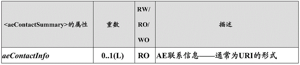
Note that in an alternative implementation, the sub-service layer may assist in discovery by creating a new AE contact summary parameter that includes a list of all AE contact information. Thus, the M2M server 1410 need only search through the aecontactsummery parameter, rather than through the entire service layer. Each time the service layer observes a request to generate AE contact information, the service layer automatically saves a copy of the contact information in the aecontactsum parameter. The aeContactSummary resource need not be updated if the contact information is already there from a previous request or if the AE has a service provider assigned AE _ ID. AE contact information may be deleted from the list if it is no longer needed, such as for example, the advertised resource is deleted. As another alternative, the M2M server 1410 may subscribe to be notified when there is a change to the aeContactSummary parameter. As a result, the M2M server 1410 is notified whenever the aeContactSummary parameter changes. The notification message may contain AE contact information that has been created, modified or deleted.
It is to be understood that the entities performing the steps shown in fig. 16 may be logical entities that may be implemented in the form of software (i.e., computer-executable instructions) stored in a memory of a device or computer system configured for wireless communication and/or network communication, such as those shown in fig. 23C or 23D, and executed on a processor of the device or computer system. That is, the method(s) shown in fig. 16 may be implemented in the form of software (i.e., computer-executable instructions) stored in a memory of a device, such as the device or computer system shown in fig. 23C or 23D, that when executed by a processor of the device, perform the steps shown in fig. 16. It is also to be understood that the functionality illustrated in FIG. 16 may be implemented as a set of virtualized network functions. The network functions may not necessarily communicate directly, but rather they may communicate via forwarding or routing functions. It is also to be understood that any of the transmitting steps and receiving steps shown in fig. 14 may be performed by the communication circuitry of the device under the control of the processor of the device and the computer-executable instructions (e.g., software) that it executes.
The M2M server may maintain a list of SLs affected by AE contact information changes. In this option, a master list of sub-service layers and associated AE contact information is maintained at M2M server 1410. The sub-service layer is responsible for keeping this master list up-to-date. A typical call flow illustrating interaction between a sub-service layer and an M2M server 1410 is shown in fig. 17. As in the previous section, assume that AE1 (with resource name: thermo control and resource ID: TCOO1) was initially registered with service layer 1 (with CSE-ID CSEOO1) and AE1 was registered with service layer 2 (with CSE-ID CSE002) after the mobility event.
In step 0 of fig. 17, assume that the M2M server 1410 has initialized the parameter aecontact list, which is used to hold the master list of AE contact information. For example, the parameter may be implemented as a resource on M2M server 1410. The information stored in this parameter is a list of AE contact information for each sub-service layer.
In step 1 of fig. 17, the sub-service layer in the gateway 2 receives the request with AE contact information. The sub-service layer sends an "add" AE contact information request to the M2M server 1410.
In step 2 of fig. 17, the M2M server 1410 extracts the AE contact information from the request and updates the appropriate entry in the aeContactList. For example, if the request in step 1 is a group creation with multiple AEs as member IDs, the request may contain more than one AE contact information.
At some later time, the sub-service layer 1 in the gateway 1 deletes the advertised resource. The resource has AE contact information.
In step 3 of fig. 17, sub-service layer 1 sends a "remove" AE contact information request to M2M server 1410.
In step 4 of fig. 17, the M2M server 1410 extracts the AE contact information from the request and removes the corresponding entry from the aeContactList. At any point in time, the M2M server 1410 has a complete view of all sub-service layers affected by AE mobility. For example, the sample aeContactList for oneM2M deployment is shown in table 1.
Table 1: example aecontactList
In step 5 of fig. 17, the M2M server 1410 knows that an AE mobility event has occurred for AE 1. Due to this AE mobility event, the AE contact information/CSEOO 1/TCOO1 is stale and needs to become/CSE 002/TC 001. The M2M server 1410 looks at the aeContactList and determines the service layers affected by the mobility event. For the example shown in Table 1, the two CSEs affected have ID CSE004 and CSE 009. The M2M server sends the UpdateContactInfoReq only to these affected service layers.
It should be appreciated that it is also possible for an entity to subscribe to be notified of changes to the aeContactList parameter. A subscription may be for a change within the entire service provider domain or for AE contact information for a particular sub-service layer.
It should be appreciated that the entity performing the steps shown in fig. 17 may be a logical entity that may be implemented in the form of software (i.e., computer-executable instructions) stored in a memory of a device or computer system configured for wireless communication and/or network communication, such as those shown in fig. 23C or 23D, and executed on a processor of the device or computer system. That is, the method(s) shown in fig. 17 may be implemented in the form of software (i.e., computer-executable instructions) stored in a memory of a device, such as the device or computer system shown in fig. 23C or 23D, that when executed by a processor of the device, perform the steps shown in fig. 17. It should also be appreciated that the functionality illustrated in FIG. 17 may be implemented as a set of virtualized network functions. The network functions may not necessarily communicate directly, but rather they may communicate via forwarding or routing functions. It should be further appreciated that any of the transmitting steps and receiving steps shown in fig. 17 may be performed by the communication circuitry of the device under the control of the processor of the device and the computer-executable instructions (e.g., software) it executes.
The sub-service layer may create a subscription at the M2M server that can send out notifications when there is an AE mobility event. In the first two options, the general approach relies on having the M2M server 1410 find SLs that need to be notified of AE mobility events, and then send new AE contact information to these SLs. In this third option, the SL subscribes to be notified if there is new AE contact information.
In this option, the sub-service layer relies on a subscription mechanism that is notified when there is an AE mobility event. A sample call flow is depicted in fig. 18.
In step 0 of fig. 18, it is initially assumed that M2M server 1410 maintains all active subscriptions to AE mobility events. This mechanism is slightly different from the subscription mechanism defined in oneM2M, as it does not necessarily relate to some events occurring on the resource. Instead, it relates to events that may be observed at the M2M server 1410. Each subscription contains the address of the requesting service layer and the AE contact information of the AE being monitored.
In step 1 of fig. 18, service layer 3 receives a request with AE contact information for AE 1. In the example shown, the request is a group creation request.
In step 2 of fig. 18, service layer 3 subscribes to be notified of AE mobility events of AE 1. It also provides the address where it wants to be notified of possible mobility events.
In step 3 of fig. 18, M2M server 1410 updates its subscription information about AE mobility events.
At some later time, the advertisement resource is deleted at the service layer 2 in step 4 of fig. 18. The ad resource has a link attribute that refers back to AE 2.
In step 5 of fig. 18, the gateway 2 service layer (SL 21406) asks the M2M server 1410 to unsubscribe from the AE monitoring event.
In step 6 of fig. 18, the M2M server 1410 updates its subscription information, thereby deleting the subscription.
In step 7 of fig. 18, a mobility event occurs for AE 1. The M2M server 1410 may determine that the event occurred using one of the methods in fig. 14 and 15. The M2M server 1410 may then go through all of its subscriptions to find those related to AE 1. Any subscription related to AE1 will be notified of AE mobility events. If the M2M server 1410 finds multiple service layers that need to be notified, it can create a group with these members and fan out the UpdateContactInfoReq.
It should be appreciated that the entity performing the steps shown in fig. 18 may be a logical entity that may be implemented in the form of software (i.e., computer-executable instructions) stored in a memory of a device or computer system configured for wireless communication and/or network communication, such as those shown in fig. 23C or 23D, and executed on a processor of the device or computer system. That is, the method(s) shown in fig. 18 may be implemented in the form of software (i.e., computer-executable instructions) stored in a memory of a device, such as the device or computer system shown in fig. 23C or 23D, that when executed by a processor of the device, perform the steps shown in fig. 18. It should also be appreciated that the functionality illustrated in FIG. 18 may be implemented as a set of virtualized network functions. The network functions may not necessarily communicate directly, but rather they may communicate via forwarding or routing functions. It should be further appreciated that any of the transmitting steps and receiving steps shown in fig. 18 may be performed by the communication circuitry of the device under the control of the processor of the device and the computer-executable instructions (e.g., software) it executes.
Examples
This section describes embodiments for implementing the methods/enhancements described herein for oneM2M architecture. Additionally, a user interface is also included in FIG. 22 to display and/or configure the relevant parameters and information.
oneM2M embodiment
The new functionality described herein may be implemented in a new Mobility (MOB) CSF 1902, the MOB CSF 1902 handling AE mobility events and possibly other mobility scenarios that may affect oneM2M layer.
Mobility CSF 1902 may be found IN IN-CSE as well as MN-CSE and ASN-CSE. This new MOB 1902 supports the procedures and processing between the M2M server 1410 and the sub-service layer as described above. Resources and procedures related to the service layer will be implemented in the CSE.
Alternatively, the new functionality described herein may be implemented in an existing CSF-e.g., discovery, registration or location of a CSF.
It should be appreciated that performing the functions illustrated in fig. 19 may be implemented in the form of software (i.e., computer-executable instructions) stored in a memory of a wireless apparatus or other device (e.g., server 1410, gateway, apparatus, or other computer system), such as one of those illustrated in fig. 23C or 23D described below, and executed on a processor of the apparatus or device. It should also be appreciated that the functionality illustrated in FIG. 19 may be implemented as a set of virtualized network functions. The network functions may not necessarily communicate directly, but rather they may communicate via forwarding or routing functions.
Mapping UpdateContactInfoReq
Using notification requests
The UpdateContactInfoReq message described above may be implemented by a NOTIFY (NOTIFY) operation. The To parameter may be set To the CSE being contacted. This may be, for example:
1) < CSEbase > resource ID of the resource,
2) < CSEbase > hierarchical address of the resource,
3) the pointoOfAccess (IP address and port, or FQDN) of the CSE issued by the CSE is in the pointoOfAccess of the CSE.
The Content parameter may include updated contact information. For example, it may include old AE contact information and/or new AE contact information.
More than one form of contact information may be included. For example, the contact information may be in the form of a resource name (/ MN-CSEOO1/CSEBase/AppName), or a resource ID (/ MN-CSEOO 1/AEOOOOO 1), or an absolute URI of the AE (IP address/port, FQDN, etc.).
In addition, the request may also include an optional requestCause parameter that informs the receiver of the reason the request was issued. Possible values for this parameter may include, for example:
AE mobility events: the originator has issued the request due to the detection of the AE mobility event.
Basic procedures are as defined in section 10.1.5 of oneM2M-TS-0001, oneM2M Functional Architecture-V-2.6.0, which is incorporated herein by reference in its entirety. The details of step 003 of the process are modified as follows:
For MN-CSE or ASN-CSE,
the CSE searches for URIs matching the provisioned old AE contact information in the notify targets attribute of the < description > resource, the membersids attribute in the < group > resource, and the link attribute in the advertised resource; and is
The CSE replaces the URI in the found attribute with the new AE contact information.
For the IN-CSE to be used,
the IN-CSE triggers the AE mobility event handling procedure.
Use UPDATE (UPDATE) request
The UpdateContactInfoReq message described herein may be implemented by an update operation to the CSE virtual resource contictInfoChange. The Content parameter may include updated contact information, which may include old AE contact information and/or new AE contact information.
More than one form of contact information may be included. For example, the contact information may be in the form of a resource name (/ MN-CSEOO1/CSEBase/AppName), or a resource ID (/ MN-CSEOO 1/AEOOOOO 1), or an absolute URI of the AE (IP address/port, FQDN, etc.). In addition, the request may also include an optional requestCause parameter that informs the receiver of the reason the request was issued. Possible values for this parameter may include, for example:
AE mobility events: the originator has issued the request due to the detection of the AE mobility event.
Basic procedures are as defined in section 10.1.5 of oneM2M-TS-0001, oneM2M Functional Architecture-V-2.6.0, which is incorporated herein by reference in its entirety. The details of step 003 of the process are modified as follows:
for MN-CSE or ASN-CSE,
the CSE searches for URIs matching the provisioned old AE contact information in the notify targets attribute of the < description > resource, the membersids attribute in the < group > resource, and the link attribute in the advertised resource; and is
The CSE replaces the URI in the found attribute with the new AE contact information.
For the IN-CSE to be used,
the IN-CSE triggers the AE mobility event handling procedure.
Modification to AE registration request
As part of the AE registration process, the AE issues a CREATE (CREATE) request to the registrar CSE. The request may include the following optional parameters: initial Registration, Local Registration and Current Registration CSE.
Initial Registration: optional parameters applicable to AE or CSE registration requests. If set to true, the receiver CSE processes the create operation as an initial registration from the originator. This may occur, for example, when the originator is pre-provisioned with the AE-ID or CSE-ID. If set to false or null, the receiver CSE handles the create operation as a re-registration request.
Local Registration: optional parameters applicable to AE registration requests. If set to true, the receiver CSE will take no positive action when an AE mobility event is detected. If set to false or null, the receiver CSE will assist the AE when it experiences an AE mobility event. For example, it may inform the IN-CSE that a mobility event has occurred.
Current Registrar CSE: optional parameters applicable to AE or CSE registration requests. . Set by the originator to the CSE-ID of the current registrar CSE. If the receiver CSE is different from the provisioned CSE-ID, this indicates to the receiver CSE that this is a re-registration request, and in case the originator was previously registered, it provides the registrar CSE with the CSE-ID of the CSE.
New attributes for advertising resources
As part of the description with respect to fig. 14, it is described that after an AE re-registers with a new registrar CSE and advertises its presence to the IN-CSE, the IN-CSE will have two advertised resources — one for the old registration and one for the new registration. Because there may be situations where it would be useful to save the old announcements (say AE moves back to the original CSE), it is recommended that the announced resources be maintained, but be placed in a "disabled" state. To accomplish this, a new status attribute may be introduced into the ad resource, as shown in bold in table 2.
Table 2: common attributes for advertised resources (excerpted from oneM2M-TS-0001, oneM2M Functional Architecture-V-2.6.0)
New filter criteria for discovery
As part of the description with respect to fig. 16, it is described that the CSE may issue a discovery request to find all matches to the AE contact information (e.g., in the advertisement link attribute, in the group member ID, or in the notification target). To achieve this, a new filter criterion is introduced to signal to the receiving CSE that the search needs to be conducted over all its AE contact information. It is shown in bold in table 3.
TABLE 3 Filter criteria Condition
If no other information is available for the originator to narrow the search, the root of the search may be set to the CSEbase of the target CSE.
New attributes for < AE > resources
As part of the description with respect to fig. 14, it is described that after an AE re-registers with a new registrar CSE and advertises its presence to the IN-CSE, the IN-CSE may delete or disable the original < AE > resource. Because there may be situations where it would be useful to save the old announcements (say AE moves back to the original CSE), it is recommended that the announced resources be maintained, but be placed in a "disabled" state. While in this state, the CSE maintains all context related to the resource and may only allow retrieval (RETRIEVE) operations for the resource. Any other operations targeting the resource are rejected with an unsuccessful Response Status Code. In addition, the content of the response message may contain additional error information (e.g., "disabled resources"). To accomplish this, a new status attribute may be introduced into the < AE > resource, as shown in bold in table 4.
Table 4: attribute for < AE > resources (taken from oneM2M-TS-0001, oneM2M Functional Architecture-V-2.6.0)
Modification for subscription/notification
As described with respect to fig. 18, a CSE may subscribe to be notified when a particular AE mobility event occurs. As a result, a CSE knowing that it has AE contact information for AE1 may subscribe to the IN-CSE to be notified when an AE mobility event exists for AE 1.
This can be achieved by introducing a new attribute to the subscribed resource and adding new notification criteria.
New event notification criteria for subscriptions
The new event notification criteria allow the CSE to monitor specific events at the CSE that are not related to some change in the parent resource of the subscribed resource, but are related to some action occurring at the CSE. In the context of the solution presented with respect to fig. 18, the event is an AE monitoring event. A < description > resource may be created under one of a < CSEbase > resource or a < node > sub-resource. Details are provided in the entries of table 5 (new entries are shown in bold).
Table 5: eventnotificationCriteria condition
New < aeContactSummary > resource
The < aeContactSummary > resource supports the solution proposed with respect to fig. 16. It provides a list of AE contact information for the CSE. Each time an AE contact information is requested to be created or deleted, it is internally updated by the CSE. The resources may be, for example:
Discovered or retrieved by the remote CSE;
advertised/mirrored to remote CSEs; and/or
Subscribed by the remote CSE.
This allows a remote CSE (typically an IN-CSE) to determine whether a hosted CSE is affected by an AE mobility event. It may reside below the CSEbase and is depicted in fig. 20. It has an attribute (aeContactInfo) defined in table 6.
TABLE 6 Attribute of < aeContactSummary >
< aeContactSummary > resource procedure
In order for the < aeContactSummary > resource to implement the above interaction, operations including create, retrieve, update, and delete are allowed.
Creation < aeContactSummary >
As mentioned above, the creation of the < aeContactSummary > resource can only be done implicitly on the CSE when the first registered CSE registers with the hosting CSE. This will create an < aeContactSummary > sub-resource below < CSEBase >.
Hosting the CSE may follow the procedure outlined below.
Step 001: the receiver may:
1) the resource id and resource name attributes of the < aeContactSummary > resource to be created are assigned.
2) The following common attributes specified in clause 9.6.1.3 of oneM2M-TS-0001, oneM2M Functional Architecture-V-2.6.0 (incorporated herein by reference in its entirety) are assigned:
a)parentID;
b)creationTime;
c) expirationTime: the hosting CSE may assign a value consistent with the expirationTime of the < AE > resource that triggered the creation of the < aeContactSummary > resource.
d) lastModifiedtime: equal to creationTime;
e)stateTag;
f) accessControlPolicyIDs: populated with an ID for < accesscontrolPolicy > containing:
i) in the privileges attribute:
1) allows for retrieval, update, and delete operations on < aeContactSummary > resources being created to the hosting CSE.
2) Allows retrieval and deletion operations for the < aeContactSummary > resource being created to the IN-CSE.
3) Any other RO (read-only) attribute of the < aeContactSummary > resource type is allocated within the limits of the receiver policy:
a) aeContactInfo: a list of URIs comprising AE contact information for < AE > resources that trigger the creation of the < AE ContactSummary > resource.
Step 002: the receiver may create an < aeContactSummary > resource.
Search < aeContactSummary >
This process may be used to retrieve the attributes of the < aeContactSummary > resource (e.g., by the IN-CSE). A general search procedure is described in clause 10.1.2 in oneM2M-TS-0001, oneM2M Functional Architecture-V-2.6.0 (incorporated herein by reference in its entirety).
TABLE 7 < aeContactSummary > retrieval
Update < aeContactSummary >
As described above with respect to fig. 16-18, updates of the < aeContactSummary > resource need not be supported. Since < AE > resources are created or deleted on the managed CSE, changes in the attributes of < aeContactSummary > resources may be made only by the managed CSE. For each new < AE > resource, the hosted CSE updates the aeContactInfo attribute and the expirationTime attribute (e.g., sets it to the expirationTime of the < AE > resource with the farthest expiration time).
Delete < aeContactSummary >
This process may be used to delete an existing < aeContactSummary > resource. Deletion of the existing < aeContactSummary > resource may terminate any further processing of the AE contact information for hosting the CSE.
TABLE 8 < aeContactSummary > delete
Additionally, the hosting CSE may implicitly delete the < aeContactSummary > resource when the last < AE > resource at the hosting CSE is deleted.
New aecontact List resources
The < aeContactList > resource supports the solution proposed with respect to fig. 17. It provides a list of AE contact information for all CSEs in the service provider domain. It is maintained only at the IN-CSE and is updated when the CSE sends an add/delete AE contact information request to the IN-CSE. It may reside below the CSEbase and is depicted in fig. 21. It has one sub-resource (< cseRef >) for each CSE that has provided AE contact information. < cseRef > has two attributes (CSE-ID and aeContactInfo) defined in table 9.
Attributes of Table 9< cseRef >
New CSE Properties (despendentaAEs)
As an alternative to using a notification or update operation to map UpdateContactInfoReq, information may be sent implicitly from the CSE to the IN-CSE by deriving a CSE exchange. The derived CSEs of CSE1 may refer to all sub-CSEs that are related to CSE1 by registration. CSE2 and CSE3 are descendents of CSE1 if CSE3 is registered with CSE2 and CSE2 is registered with CSE 1. As a result of the registration between the registered CSE and the registrar CSE, the registrar CSE will maintain < remoteCSE > resources for the registered CSE. The < remoteCSE > resource includes attributes of the registered party CSE.
Derived CSE exchanges rely on the enrollee CSEs recursively pushing attributes to their registrar CSEs (via their < remoteCSE > resources). The attribute is pushed from one registered CSE to its registrar CSE, then from the registrar CSE (acting as the registered CSE) to its registrar CSE, and so on until the attribute is pushed to the IN-CSE. For example, consider the case where CSE3 is registered with CSE2, CSE2 is registered with CSE1, and CSE1 is registered with IN-CSE. CSE3 updates its attributes in the < remoteCSE > resource in CSE 2. CSE2 updates its attributes IN the < remotecCSE > resource IN CSE1, and CSE1 updates its attributes IN the < remotecCSE > resource IN the IN-CSE.
The proposed attribute is the despendentaes attribute. This is a new attribute for < CSE > resources and < remoteCSE > resources. The attribute has a weight 0..1(L) and is readable/writable.
The attributes contain an aecontact list in the form of a set of (CSE ID, application entity resource ID) pairs. The attributes are initialized when a < CSE > resource is created.
The attributes are modified when a service with an application entity resource ID is started, updated, or deleted. For example, when a < description > resource has a notify uri attribute containing an application entity resource ID, or when a < group > resource has a member of a memberList attribute containing an application entity resource ID, or when an advertised resource has a link attribute pointing to an application entity resource ID. When the despendentaes attribute of the < remoteCSE > resource is modified, the attribute is also modified.
When a service is started, a resource is created and if the resource contains a reference to an application entity resource ID, the hosting CSE will include the (CSE ID, application entity resource ID) pair in its descementages attribute. The hosting CSE will also update its descementaEs attribute of the < remotecCSE > resource on its registrar CSE.
When the service is stopped, the resource is deleted and if the resource contains a reference to an application entity resource ID, the hosting CSE will delete (CSE ID, application entity resource ID) pair from its descedentaaes attribute. The hosting CSE will also update its descementaEs attribute of the < remotecCSE > resource on its registrar CSE.
When a service is modified, the resources related to the service are modified and if it has a reference to an added (or deleted) application entity resource ID, the hosting CSE will include the (CSE ID, application entity resource ID) pair in its descementeaes attribute (or remove the (CSE ID, application entity resource ID) pair). The hosting CSE will also update its descementaEs attribute of the < remotecCSE > resource on its registrar CSE.
When the desendentaes attribute of the < remoteCSE > resource is changed, the registrar CSE will update the desendentaes attribute of the < CSE > resource accordingly — remove/add/modify the entry accordingly.
Each change IN the desendentaes attributes IN any CSE IN the M2M/IoT system is propagated to the IN-CSE. The desendentaes attribute of the IN-CSE will have the full AEContactList as presented with respect to FIG. 17.
Graphic user interface
Interfaces such as Graphical User Interfaces (GUIs) 2202 and 2204 may be used to assist a user in controlling or configuring functions related to mobility management of an application. The user interface may be added to the CSE to:
Monitoring/displaying AE contact information results at an intermediate node or terminal device supporting the service layer. This allows the user to view the aeContactSummary as defined with respect to fig. 16 (e.g., interface 2202);
monitoring/displaying AE contact information results for the entire service provider domain at the infrastructure node. This allows the user to view the aecontact list as defined with respect to fig. 17 (e.g., interface 2204);
discovery of CSEs affected by AE mobility events (this at infrastructure nodes);
manually update AE contact information at the CSE (either an intermediate node supporting the service layer, a terminal device, or an infrastructure node); and/or
Trigger the MN-CSE to send the UpdateContactInfoReq to the IN-CSE (at an intermediate node or end device supporting the service layer).
It should be appreciated that the interfaces 2202 and 2204 can be generated using displays such as those shown in fig. 23C-D described below.
Example Environment
Fig. 23A is a diagram of an example machine-to-machine (M2M), internet of things (IoT), or world of things (WoT) communication system 10 in which one or more disclosed embodiments may be implemented in communication system 10. Generally, M2M technology provides building blocks for the IoTAVoT, and any M2M device, M2M gateway, M2M server, or M2M service platform may be a component or node of the IoTAVoT and IoTAVoT service layer, etc. Any of the client, proxy or server devices shown in any of fig. 2-4, 6-19 or 22 may comprise a node of a communication system (such as those shown in fig. 23A-D).
The service layer may be a functional layer within a network service architecture. The service layer is typically located above the application protocol layer (such as HTTP, CoAP, or MQTT) and provides value-added services for client applications. The service layer also provides an interface for the core network at lower resource layers, such as, for example, a control layer and a transport/access layer. The service layer supports multiple categories of (service) capabilities or functions, including service definition, service runtime enablement, policy management, access control, and service clustering. Recently, several industry standards bodies (e.g., oneM2M) have been developing the M2M service layer to address challenges associated with the integration of M2M type devices and applications into deployments such as the internet/Web, cellular networks, enterprise networks, and home networks. The M2M service layer may provide applications and/or various devices with access to a set or set of the above capabilities or functions that the service layer may be referred to as a CSE or SCL supports. Several examples include, but are not limited to, security, charging, data management, device management, discovery, deployment, and connection management that various applications may typically use. These capabilities or functions are made available to such various applications via APIs using message formats, resource structures, and resource representations defined by the M2M service layer. A CSE or SCL is a functional entity, which may be implemented in hardware and/or software, that provides (service) capabilities or functions exposed to various applications and/or devices (i.e., functional interfaces between such functional entities) in order for them to use such capabilities or functions.
As shown in fig. 23A, M2M/IoT/WoT communication system 10 includes communication network 12. The communication network 12 may be a fixed network (e.g., ethernet, fiber optic, ISDN, PLC, etc.) or a wireless network (e.g., WLAN, cellular, etc.) or a heterogeneous network. For example, the communication network 12 may be comprised of multiple access networks that provide content (such as voice, data, video, messaging, broadcast, etc.) to multiple users. For example, communication network 12 may employ one or more channel access methods, such as Code Division Multiple Access (CDMA), Time Division Multiple Access (TDMA), Frequency Division Multiple Access (FDMA), orthogonal FDMA (ofdma), single carrier FDMA (SC-FDMA), and the like. Further, the communication network 12 may include other networks such as, for example, a core network, the internet, a sensor network, an industrial control network, a personal area network, a converged personal network, a satellite network, a home network, or an enterprise network.
As shown in fig. 23A, the M2M/IoT/WoT communication system 10 may include an infrastructure domain and a field domain. The infrastructure domain refers to the network side of the end-to-end M2M deployment, and the domain refers to the regional network typically behind the M2M gateway. Both the domain and the infrastructure domain may include various different nodes of the network (e.g., servers, gateways, devices, etc.). For example, a domain may include M2M gateway 14 and devices 18. It will be appreciated that any number of M2M gateway devices 14 and M2M devices 18 may be included in the M2M/IoT/WoT communication system 10 as desired. Each of the M2M gateway devices 14 and the M2M devices 18 is configured to send and receive signals using communication circuitry via the communication network 12 or a direct radio link. The M2M gateway 14 allows wireless M2M devices (e.g., cellular and non-cellular) and fixed network M2M devices (e.g., PLC) to communicate over a carrier network, such as the communication network 12, or direct radio link. For example, the M2M devices 18 may collect data and send the data to the M2M applications 20 or other M2M devices 18 via the communication network 12 or a direct radio link. The M2M device 18 may also receive data from the M2M application 20 or the M2M device 18. Further, as described below, data and signals may be sent to the M2M application 20 and received from the M2M application 20 via the M2M service layer 22. The M2M devices 18 and the gateway 14 may communicate via various networks including, for example, cellular, WLAN, WPAN (e.g., ZigBee, 6L0WPA, bluetooth), direct radio link, and wire. Exemplary M2M devices include, but are not limited to, tablets, smart phones, medical devices, temperature and weather monitors, connected automobiles, smart meters, game consoles, personal digital assistants, health and fitness monitors, lights, thermostats, appliances, garage doors, and other actuator-based devices, security devices, and smart sockets.
Referring to fig. 23B, the illustrated M2M service layer 22 in the farm domain provides services for M2M applications 20, M2M gateways 14, M2M devices 18, and communication networks 12. It will be appreciated that the M2M service layer 22 may communicate with any number of M2M applications, M2M gateways 14, M2M devices 18, and communication networks 12 as desired. The M2M service layer 22 may be implemented by one or more nodes of a network, which may include servers, computers, devices, etc. The M2M service layer 22 provides service capabilities applicable to M2M devices 18, M2M gateways 14, and M2M applications 20. The functionality of the M2M service layer 22 may be implemented in various ways, e.g., as a web server, in a cellular core network, in a cloud, etc.
Similar to the illustrated M2M service layer 22, there is an M2M service layer 22' in the infrastructure domain. The M2M service layer 22 'provides services for the M2M applications 20' in the infrastructure domain and the underlying communication network 12. The M2M service layer 22' also provides services for M2M gateways 14 and M2M devices 18 in the farm. It will be appreciated that the M2M service layer 22' may communicate with any number of M2M applications, M2M gateways, and M2M devices. The M2M service layer 22' may interact with the service layer through different service providers. The M2M service layer 22' may be implemented by one or more nodes of a network, which may include servers, computers, appliances, virtual machines (e.g., cloud computing/storage farms, etc.).
Referring also to fig. 23B, M2M service layers 22 and 22' provide a set of service delivery capabilities for cores that different applications and verticals may utilize. These service capabilities enable the M2M applications 20 and 20' to interact with devices and perform functions such as data collection, data analysis, device management, security, accounting, service/device discovery, and the like. Essentially, these service capabilities leave applications without the burden of implementing these functions, thereby simplifying application deployment and reducing costs and time to market. The service layers 22 and 22 ' also enable the M2M applications 20 and 20 ' to communicate over various networks, such as the network 12 related to the services provided by the service layers 22 and 22 '.
The M2M applications 20 and 20' may include applications in various industries, such as, but not limited to, transportation, health and wellness, networked home, energy management, asset tracking, and security and surveillance. As described above, the M2M service layer running across devices, gateways, servers, and other nodes of the system supports functions such as, for example, data collection, device management, security, accounting, location tracking/geo-fencing, device/service discovery, and legacy system integration, and provides these functions as services to the M2M applications 20 and 20'.
In general, a service layer, such as service layers 22 and 22' shown in FIG. 23B, defines a software middleware layer that supports value added service capabilities through a set of Application Programming Interfaces (APIs) and underlying networking interfaces. Both ETSI M2M and oneM2M architectures define service layers. The service layer of ETSI M2M is referred to as the Service Capability Layer (SCL). SCLs may be implemented in various different nodes of the ETSI M2M architecture. For example, an instance of the service layer may be implemented within an M2M device (where it is referred to as a device scl (dscl)), within a gateway (where it is referred to as a gateway scl (gscl)), and/or within a network node (where it is referred to as a network scl (nscl)). The oneM2M service layer supports a set of Common Service Functions (CSFs) (i.e., service capabilities). Instantiations of a set of one or more particular types of CSFs are referred to as Common Service Entities (CSEs), which may be hosted on different types of network nodes (e.g., infrastructure nodes, intermediate nodes, application-specific nodes). The third generation partnership project (3GPP) has also defined an architecture for Machine Type Communication (MTC). In this architecture, the service layer and the service capabilities it provides are implemented as part of a Service Capability Server (SCS). Whether implemented in DSCL, GSCL, or NSCL of ETSI M2M architecture, in a Service Capability Server (SCS) of 3GPP MTC architecture, in CSF or CSE of oneM2M architecture, or in some other node of the network, an instance of the service layer may be implemented as a logical entity (e.g., software, computer-executable instructions, etc.) executing on one or more separate nodes (including servers, computers, and other computing devices or nodes) in the network, or as part of one or more existing nodes. By way of example, instances of the service layer or components thereof may be implemented in the form of software running on a network node (e.g., server, computer, gateway, appliance, etc.) having the general architecture shown in fig. 23C or 23D described below.
Further, the methods and functions described herein may be implemented as part of an M2M network that accesses services using a Service Oriented Architecture (SOA) and/or a Resource Oriented Architecture (ROA).
Fig. 23C is a block diagram of an example hardware/software architecture of a node of a network, such as one of the clients, servers, or proxies shown in fig. 2-4, 6-19, or 22 that may operate as an M2M server, gateway, appliance, or other node in an M2M network, such as the nodes shown in fig. 23A and 23B. As shown in fig. 23C, the node 30 may include a processor 32, non-removable memory 44, removable memory 46, a speaker/microphone 38, a keypad 40, a display, a touch pad and/or indicator 42, a power supply 48, a Global Positioning System (GPS) chipset 50, and other peripherals 52. The node 30 may also include communication circuitry, such as a transceiver 34 and a transmit/receive element 36. It will be appreciated that node 30 may include any subcombination of the foregoing elements while remaining consistent with an embodiment. The node may be a node implementing mobility management for an application as described herein (e.g., in relation to the methods described with reference to fig. 6A-B, 7, 8, and 13-18 or the data structures of fig. 1-6B, 10-12, and 19-21, tables 1-9, or claims).
The processor 32 may be a general-purpose processor, a special purpose processor, a conventional processor, a Digital Signal Processor (DSP), a plurality of microprocessors, one or more microprocessors in association with a DSP core, a controller, a microcontroller, Application Specific Integrated Circuits (ASICs), Field Programmable Gate Arrays (FPGAs) circuits, any other type of Integrated Circuit (IC), a state machine, or the like. In general, the processor 32 may execute computer-executable instructions stored in a memory of the node (e.g., memory 44 and/or memory 46) in order to perform various desired functions of the node. For example, processor 32 may perform signal decoding, data processing, power control, input/output processing, and/or any other functionality that enables node 30 to operate in a wireless or wired environment. The processor 32 may run application layer programs (e.g., a browser) and/or radio access layer (RAN) programs and/or other communication programs. The processor 32 may also perform security operations such as, for example, authentication, security key agreement, and/or cryptographic operations at the access layer and/or application layer.
As shown in fig. 23C, the processor 32 is coupled to its communication circuitry (e.g., transceiver 34 and transmit/receive element 36). Processor 32, through execution of the computer-executable instructions, may control the communication circuitry to communicate node 30 with other nodes via the network to which it is connected. In particular, processor 32 may control the communication circuitry to perform the transmitting steps and receiving steps described herein (e.g., in fig. 6A-B, 7, 8, 13-18, and 25) and in the claims. Although fig. 23C depicts the processor 32 and the transceiver 34 as separate components, it will be appreciated that the processor 32 and the transceiver 34 may be integrated together in an electronic package or chip.
The transmit/receive element 36 may be configured to transmit signals to or receive signals from other nodes, including M2M servers, gateways, appliances, and the like. For example, in an embodiment, the transmit/receive element 36 may be an antenna configured to transmit and/or receive RF signals. The transmit/receive element 36 may support various networks and air interfaces such as WLAN, WPAN, cellular, etc. In embodiments, the transmit/receive element 36 may be an emitter/detector configured to transmit and/or receive, for example, IR, UV, or visible light signals. In yet another embodiment, the transmit/receive element 36 may be configured to transmit and receive both RF signals and optical signals. It will be appreciated that the transmit/receive element 36 may be configured to transmit and/or receive any combination of wireless or wired signals.
Additionally, although transmit/receive element 36 is depicted in fig. 23C as a single element, node 30 may include any number of transmit/receive elements 36. More specifically, node 30 may employ MIMO technology. Thus, in an embodiment, the node 30 may include two or more transmit/receive elements 36 (e.g., multiple antennas) for transmitting and receiving wireless signals.
Transceiver 34 may be configured to modulate signals to be transmitted by transmit/receive element 36 and demodulate signals received by transmit/receive element 36. As noted above, the node 30 may have multi-node capabilities. Thus, the transceiver 34 may include multiple transceivers for enabling the node 30 to communicate via multiple RATs (such as UTRA and IEEE 802.11, for example).
The processor 32 may access information from and store data in any type of suitable memory, such as non-removable memory 44 and/or removable memory 46. For example, as described above, the processor 32 may store the session context in its memory. The non-removable memory 44 may include Random Access Memory (RAM), Read Only Memory (ROM), a hard disk, or any other type of memory storage device. The removable memory 46 may include a Subscriber Identity Module (SIM) card, a memory stick, a Secure Digital (SD) memory card, or the like. In other embodiments, the processor 32 may access information from and store data in memory that is not physically located on the node 30 (such as on a server or home computer). The processor 32 may be configured to control a lighting pattern, image or color on the display or indicator 42 to reflect the status of the node or to configure the node, particularly the underlying network, application or other service in communication with the node. In one embodiment, the display/indicator 42 may present the graphical user interface shown in fig. 25 and described herein.
Processor 32 may receive power from power supply 48 and may be configured to distribute power to other components in node 30 and/or control power to other components in node 30. Power supply 48 may be any suitable device for providing power to node 30. For example, power source 48 may include one or more dry cell batteries (e.g., nickel cadmium (NiCd), nickel zinc (NiZn), nickel metal hydride (NiMH), lithium ion (Li-ion), etc.), solar cells, fuel cells, and the like.
The processor 32 may also be coupled to a GPS chipset 50, the GPS chipset 50 configured to provide location information (e.g., longitude and latitude) regarding the current location of the node 30. It will be appreciated that, while consistent with embodiments, node 30 may obtain location information by any suitable location determination method.
The
processor 32 may be further coupled with
other peripherals 52, which
other peripherals 52 may include one or more software and/or hardware modules that provide additional features, functionality, and/or wired or wireless connectivity. For example,
peripherals 52 can include various sensors, such as an accelerometer, a biometric (e.g., fingerprint) sensor, an electronic compass, a satellite transceiver, a sensor, a digital camera (for photo or video), a Universal Serial Bus (USB) port or other interconnection interface, a vibrating device, a television transceiver, a hands-free headset, a microphone, a,
Modules, Frequency Modulated (FM) radios, digital music players, media players, video game player modules, internet browsers, and the like.
The nodes 30 may be included in other devices or apparatuses, such as sensors, consumer electronics, wearable apparatuses (such as smartwatches or smart clothing), medical or electronic health apparatuses, robots, industrial equipment, drones, vehicles (such as cars, trucks, trains, or airplanes). Node 30 may be connected to other components, modules or systems of such devices or apparatuses via one or more interconnect interfaces, such as an interconnect interface that may include one of peripherals 52.
Fig. 23D is a block diagram of an exemplary computing system 90, which computing system 90 may also be used to implement one or more nodes of a network, such as a client, server, or proxy, shown in fig. 2-4, 6-19, or 22 and described herein, that may operate as an M2M server, gateway, appliance, or other node in an M2M network, such as the nodes shown in fig. 23A and 23B.
The computing system 90 may comprise a computer or server and may be controlled primarily by computer readable instructions, which may be in the form of software, wherever or by any means such instructions are stored or accessed. Such computer readable instructions may be executed within a processor, such as Central Processing Unit (CPU)91, to cause the computing system 90 to do work. In many known workstations, servers, and personal computers, the central processing unit 91 is implemented by a single-chip CPU called a microprocessor. In other machines, the central processing unit 91 may include multiple processors. Coprocessor 81 is an optional processor other than main CPU 91 that performs additional functions or assists CPU 91. CPU 91 and/or coprocessor 81 may receive, generate, and process data associated with the disclosed systems and methods for E2E M2M service layer sessions, such as receiving session credentials or authenticating based on the session credentials.
In operation, CPU 91 fetches, decodes, and executes instructions and transfers information to and from other resources via the computer's primary data transfer path, system bus 80, and other resources. Such a system bus connects the components in computing system 90 and defines a medium for data exchange. The system bus 80 typically includes data lines for sending data, address lines for sending addresses, and control lines for sending interrupts and for operating the system bus. An example of such a system bus 80 is a PCI (peripheral component interconnect) bus.
The memory coupled to system bus 80 includes Random Access Memory (RAM)82 and Read Only Memory (ROM) 93. Such memories include circuitry that allows information to be stored and retrieved. The ROM 93 typically includes stored data that cannot be easily modified. The data stored in the RAM 82 can be read or changed by the CPU 91 or other hardware devices. Access to the RAM 82 and/or ROM 93 may be controlled by a memory controller 92. The memory controller 92 may provide address translation functionality that translates virtual addresses to physical addresses when instructions are executed. Memory controller 92 may also provide memory protection functions that isolate processing within the system and isolate system processing from user processing. Thus, a program running in the first mode may only access memory mapped by its own processed virtual address space; it cannot access memory within the virtual address space of another process unless the memory shared between the processes has been set.
In addition, computing system 90 may contain a peripheral controller 83, peripheral controller 83 being responsible for communicating instructions from CPU 91 to peripherals such as printer 94, keyboard 84, mouse 95, and hard disk drive 85.
The display 86, controlled by a display controller 96, may be used to display visual output generated by the computing system 90. Such visual output may include text, graphics, animated graphics, and video. The display 86 may be implemented with a CRT-based video display, an LCD-based flat panel display, a gas plasma-based flat panel display, or a touch panel. The display controller 96 includes the electronic components necessary to generate the video signals sent to the display 86. The combination of the display 86 and the computer-executable instructions executed by the CPU 91 may generate and operate the graphical user interface illustrated and described in fig. 25 and the accompanying description.
Further, the computing system 90 may contain communication circuitry, such as, for example, a network adapter 97, which may be used to connect the computing system 90 to an external communication network (such as the network 12 of fig. 23A-D) to enable the computing system 90 to communicate with other devices of the network. The network circuitry, alone or in combination with CPU 91, may be used to perform the transmitting and receiving steps described herein (e.g., in fig. 1, 3, 5-8, 11-15, 20-21, 24, or 25) and in the claims.
It is to be appreciated that any or all of the systems, methods, and processes described herein may be embodied in the form of computer-executable instructions (i.e., program code) stored on a computer-readable storage medium, which when executed by a machine (such as an apparatus of an M2M network, including, for example, an M2M server, gateway, appliance, etc.), performs and/or implements the systems, methods, and processes described herein. In particular, any of the above-described steps, operations, or functions may be embodied in the form of such computer-executable instructions. Computer-readable storage media include volatile and nonvolatile, removable and non-removable media implemented in any non-transitory (i.e., tangible or physical) method or technology for storage of information, but such computer-readable storage media do not include signals. Computer-readable storage media includes, but is not limited to, RAM, ROM, EEPROM, flash memory or other memory technology, CD-ROM, Digital Versatile Disks (DVD) or other optical disk storage, magnetic cassettes, magnetic tape, magnetic disk storage or other magnetic storage devices, or any other tangible or physical medium which can be used to store the desired information and which can be accessed by a computer.
This written description uses examples to disclose the invention, including the best mode, and also to enable any person skilled in the art to practice the invention, including making and using any devices or systems and performing any incorporated methods. The patentable scope of the invention is defined by the claims, and may include other examples that occur to those skilled in the art. Such other examples are intended to be within the scope of the claims if they have elements that do not differ from the literal language of the claims, or if they include equivalent elements with insubstantial differences from the literal languages of the claims.