CN109963796B - beverage preparation container - Google Patents
beverage preparation container Download PDFInfo
- Publication number
- CN109963796B CN109963796B CN201780068001.1A CN201780068001A CN109963796B CN 109963796 B CN109963796 B CN 109963796B CN 201780068001 A CN201780068001 A CN 201780068001A CN 109963796 B CN109963796 B CN 109963796B
- Authority
- CN
- China
- Prior art keywords
- membrane
- container
- beverage
- filter disc
- coupled
- Prior art date
- Legal status (The legal status is an assumption and is not a legal conclusion. Google has not performed a legal analysis and makes no representation as to the accuracy of the status listed.)
- Expired - Fee Related
Links
Images


Classifications
-
- B—PERFORMING OPERATIONS; TRANSPORTING
- B65—CONVEYING; PACKING; STORING; HANDLING THIN OR FILAMENTARY MATERIAL
- B65D—CONTAINERS FOR STORAGE OR TRANSPORT OF ARTICLES OR MATERIALS, e.g. BAGS, BARRELS, BOTTLES, BOXES, CANS, CARTONS, CRATES, DRUMS, JARS, TANKS, HOPPERS, FORWARDING CONTAINERS; ACCESSORIES, CLOSURES, OR FITTINGS THEREFOR; PACKAGING ELEMENTS; PACKAGES
- B65D85/00—Containers, packaging elements or packages, specially adapted for particular articles or materials
- B65D85/70—Containers, packaging elements or packages, specially adapted for particular articles or materials for materials not otherwise provided for
- B65D85/804—Disposable containers or packages with contents which are mixed, infused or dissolved in situ, i.e. without having been previously removed from the package
- B65D85/8043—Packages adapted to allow liquid to pass through the contents
- B65D85/8052—Details of the outlet
-
- B—PERFORMING OPERATIONS; TRANSPORTING
- B65—CONVEYING; PACKING; STORING; HANDLING THIN OR FILAMENTARY MATERIAL
- B65D—CONTAINERS FOR STORAGE OR TRANSPORT OF ARTICLES OR MATERIALS, e.g. BAGS, BARRELS, BOTTLES, BOXES, CANS, CARTONS, CRATES, DRUMS, JARS, TANKS, HOPPERS, FORWARDING CONTAINERS; ACCESSORIES, CLOSURES, OR FITTINGS THEREFOR; PACKAGING ELEMENTS; PACKAGES
- B65D85/00—Containers, packaging elements or packages, specially adapted for particular articles or materials
- B65D85/70—Containers, packaging elements or packages, specially adapted for particular articles or materials for materials not otherwise provided for
- B65D85/804—Disposable containers or packages with contents which are mixed, infused or dissolved in situ, i.e. without having been previously removed from the package
- B65D85/8043—Packages adapted to allow liquid to pass through the contents
- B65D85/8061—Filters
-
- A—HUMAN NECESSITIES
- A23—FOODS OR FOODSTUFFS; TREATMENT THEREOF, NOT COVERED BY OTHER CLASSES
- A23F—COFFEE; TEA; THEIR SUBSTITUTES; MANUFACTURE, PREPARATION, OR INFUSION THEREOF
- A23F5/00—Coffee; Coffee substitutes; Preparations thereof
- A23F5/24—Extraction of coffee; Coffee extracts; Making instant coffee
- A23F5/26—Extraction of water soluble constituents
- A23F5/262—Extraction of water soluble constituents the extraction liquid flowing through a stationary bed of solid substances, e.g. in percolation columns
-
- A—HUMAN NECESSITIES
- A47—FURNITURE; DOMESTIC ARTICLES OR APPLIANCES; COFFEE MILLS; SPICE MILLS; SUCTION CLEANERS IN GENERAL
- A47J—KITCHEN EQUIPMENT; COFFEE MILLS; SPICE MILLS; APPARATUS FOR MAKING BEVERAGES
- A47J31/00—Apparatus for making beverages
- A47J31/40—Beverage-making apparatus with dispensing means for adding a measured quantity of ingredients, e.g. coffee, water, sugar, cocoa, milk, tea
- A47J31/407—Beverage-making apparatus with dispensing means for adding a measured quantity of ingredients, e.g. coffee, water, sugar, cocoa, milk, tea with ingredient-containing cartridges; Cartridge-perforating means
-
- A—HUMAN NECESSITIES
- A47—FURNITURE; DOMESTIC ARTICLES OR APPLIANCES; COFFEE MILLS; SPICE MILLS; SUCTION CLEANERS IN GENERAL
- A47J—KITCHEN EQUIPMENT; COFFEE MILLS; SPICE MILLS; APPARATUS FOR MAKING BEVERAGES
- A47J31/00—Apparatus for making beverages
- A47J31/44—Parts or details or accessories of beverage-making apparatus
- A47J31/4403—Constructional details
-
- B—PERFORMING OPERATIONS; TRANSPORTING
- B65—CONVEYING; PACKING; STORING; HANDLING THIN OR FILAMENTARY MATERIAL
- B65D—CONTAINERS FOR STORAGE OR TRANSPORT OF ARTICLES OR MATERIALS, e.g. BAGS, BARRELS, BOTTLES, BOXES, CANS, CARTONS, CRATES, DRUMS, JARS, TANKS, HOPPERS, FORWARDING CONTAINERS; ACCESSORIES, CLOSURES, OR FITTINGS THEREFOR; PACKAGING ELEMENTS; PACKAGES
- B65D85/00—Containers, packaging elements or packages, specially adapted for particular articles or materials
- B65D85/70—Containers, packaging elements or packages, specially adapted for particular articles or materials for materials not otherwise provided for
- B65D85/804—Disposable containers or packages with contents which are mixed, infused or dissolved in situ, i.e. without having been previously removed from the package
- B65D85/8043—Packages adapted to allow liquid to pass through the contents
- B65D85/8055—Means for influencing the liquid flow inside the package
Landscapes
- Engineering & Computer Science (AREA)
- Mechanical Engineering (AREA)
- Food Science & Technology (AREA)
- Life Sciences & Earth Sciences (AREA)
- Chemical & Material Sciences (AREA)
- Polymers & Plastics (AREA)
- Apparatus For Making Beverages (AREA)
- Data Exchanges In Wide-Area Networks (AREA)
- Pharmaceuticals Containing Other Organic And Inorganic Compounds (AREA)
Abstract
A capsule for preparing a beverage in an automatic beverage preparation device, comprising a cup-shaped body defined by a transverse wall and by a bottom wall having a beverage outflow opening, and closed by a cover perforable to allow the injection of a fluid into the capsule. The container further comprises a filter assembly extending transversely to a longitudinal axis of the container to divide an interior volume of the container into an upper chamber for containing a beverage preparation substance and a lower chamber for collecting the beverage. The filter assembly comprises a relatively rigid filter disc provided with a through opening and two membranes stacked on and directly coupled to a face of the filter disc facing the lower chamber.
Description
Technical Field
The present invention relates to a beverage preparation container.
In particular, the present invention relates to a capsule suitable for use in an automatic beverage preparation device, comprising a cup-shaped body defined by a transverse wall and a bottom wall, the bottom wall being provided with a beverage outflow opening, and the cup-shaped body being closed by a cover perforable to allow the injection of a fluid into the capsule; the container further comprises a filter assembly extending transverse to a longitudinal axis of the container to divide an interior volume of the container into an upper chamber for containing a beverage preparation substance and a lower chamber for collecting the beverage.
Background
Containers for use in automatic beverage preparation devices are known, for example, from:
EP 2998242, which discloses a container comprising: an outer body having a longitudinal axis; a filter disc arranged in the outer body transversely to the longitudinal axis to define an upper chamber for containing the product to be infused and a lower chamber for collecting the beverage; and a membrane arranged below the filter disc and defining with the filter disc an intermediate chamber for containing the aromatic substance;
WO 2014/037339, which discloses a container comprising: a filter disc provided with perforating means and intended to define, in the container, an upper chamber for containing the product to be infused and a lower chamber for collecting the beverage; the container further comprises: an aluminum membrane disposed in the upper chamber to tear open the filter disk due to an increase in pressure in the upper chamber; and a plastic membrane arranged in the upper chamber above the aluminium membrane and provided with a pre-cut having a drip-proof function;
WO2015/049270, which discloses a container internally provided with an upper guide tube extending upwardly from a bottom wall and communicating with an outlet duct. In use, the brewed beverage flows from the bottom of the capsule towards the cover and out through the outlet conduit;
US2010/260895, which discloses a container having an outer cup body closed by a wall through which beverage can flow. The wall comprises at least a first layer and a second layer each provided with at least one aperture through which the beverage can flow.
Other vessels are known from US2012/121780a1, US2010/260895a1, WO2015/177591a1, WO2014/126463a1, WO2015/049270a 1.
Disclosure of Invention
It is an object of the present invention to provide an improved container of the above-mentioned type and which allows for an improved beverage delivery process and aesthetic and organoleptic properties of the beverage, while at the same time being cost-effective and easy to manufacture.
According to the present invention, there is provided a beverage preparation container as claimed in the appended claims.
Drawings
The invention will now be described with reference to the accompanying drawings, which illustrate non-limiting embodiments, in which:
FIG. 1 illustrates, in cross-section, a container according to a preferred embodiment of the present invention;
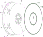
FIG. 2 is an exploded view of a detail of the container of FIG. 1;
FIG. 3 shows a plan view of a detail of FIG. 2;
figures 4 to 7 show various variants of the detail of figure 2 in exploded views; and
fig. 8 shows a plan view of a detail of fig. 7.
Detailed Description
In fig. 1, the reference numeral 1 designates in its entirety a container for containing an infusion or soluble substance for preparing a beverage, such as, for example, coffee, tea, chocolate, milk, broth, etc.
The capsule 1 is suitable for use in an apparatus (not shown) of a known type, in which the beverage preparation process comprises arranging the capsule in a sealed base and supplying a pressurized hot or cold fluid, usually water, in the capsule, so as to percolate or dissolve the substance contained in the capsule and thereby obtain the beverage.
As shown in fig. 1, the capsule 1 comprises a cup-shaped body 2 having a longitudinal axis 3 and closed at its upper end by a cover 4, constituted by a single-layer or multilayer film made of plastic and/or metal material and hermetically welded to an outer annular flange 5 of the cup-shaped body 2, which, in use, is perforated by perforating means (not shown) of the automatic beverage preparation device to allow the injection of a fluid, typically water, into the capsule 1 at a defined temperature and pressure.
The cup-shaped body 2 comprises a lateral wall 6 coaxial with the axis 3 and flaring generally, preferably but not necessarily, outwards towards the annular flange 5, and a bottom wall 7, the bottom wall 7 extending in a direction substantially transverse to the axis 3 and having a beverage outflow opening 8.
The cup-shaped body 2 is made of an impermeable material, preferably plastic for food use, in Particular Polypropylene (PP) or polybutylene terephthalate (PBT), and can be obtained by any suitable moulding process, in particular by thermoforming.
As shown in fig. 1, the container 1 further comprises a filter assembly 9 extending in the container 1 in a direction substantially transverse to the axis 3, so as to divide the internal volume of the container 1 into an upper chamber 10 for containing the infusion or soluble substance and a lower or collection chamber 11 into which the beverage coming from the upper chamber 10 flows and then from the container 1 through the beverage outflow opening 8.
Depending on the type and amount of substance contained in the container 1 and/or the degree of compaction that the substance should have, the substance in the upper chamber 10 may occupy all or only part of the volume between the filter assembly 9 and the cover 4.
In particular, as in the case of the container shown in fig. 1, if the substance is an infusion substance, for example coffee, the volume of the lower chamber 10 occupied by the substance is delimited at the bottom by the filter assembly 9 and at the top by a microporous foil 12 welded to the side wall 6 at a distance from the cover 4. The microporous foil 12 also has the function of facilitating an even distribution and penetration of the infusion fluid into the substance when the infusion fluid is supplied to the container 1 through the cover 4.
The filter assembly 9 comprises a relatively rigid disc 13 fixedly secured to the side wall 6, bounded at the top by a face 14 facing the upper chamber 10 and at the bottom by a face 15 facing the lower chamber 11, and provided with a plurality of through openings 16 extending between the faces 14 and 15.
According to the preferred embodiment shown in fig. 1, disk 13 has a peripheral portion 17 which sits on a flat annular portion 18 of lateral wall 6, transverse to axis 3, and is delimited circumferentially by an edge arranged in contact with lateral wall 6.
In order to bring disk 13 into firm contact with flat annular portion 18 of lateral wall 6 and prevent it from lifting and moving towards the inside of chamber 10 in use, lateral wall 6 is provided with a retaining member which engages at the top with peripheral portion 17 of disk 13 and is defined by an annular projection 21 projecting towards the inside of container 1.
The opening 16 of the disk 13 can have different shapes and sizes, depending on the type of beverage the container 1 is intended to make. By way of example only, in the container shown in fig. 1, opening 16 is defined by a plurality of holes uniformly distributed over the central annular portion of disk 13. According to the variant shown in fig. 7, the opening 16 is defined by a plurality of cross-shaped precuts distributed around the axis 3.
The disc 13 of the filter assembly 9 comprises a central tip 19 projecting from the face 15 of the disc 13 coaxially to the axis 3 and having, in use, the function of perforating a sealing film 20 welded to the inside of the bottom wall 7 before the beverage flows out of the opening 8, so as to allow the beverage to flow out of the capsule 1.
For this purpose, the tip 19 has a height, measured parallel to the axis 3, lower than the distance between the face 15 and the sealing membrane 20, and the side wall 6 has a deformable annular portion 21 arranged between the disk 13 and the beverage outflow opening 8 and designed to collapse axially when, in use, the container 1 is compressed inside the above-mentioned seat of the automatic beverage preparation device, with the subsequent axial displacement of the tip 19 towards and through the sealing membrane 20.
As shown in fig. 2 to 8, in addition to the disk 13, the filter assembly 9 comprises two blocking members arranged downstream of the disk 13 in the outflow direction of the beverage and defined by two membranes 21 and 22 facing each other and in direct contact with each other and coupled to the disk 13 according to various methods to be described below.
The septum 21 is arranged between the disc 13 and the septum 22 and has the function of sealing the upper chamber 10 containing the infusion substance and of tearing, in use, due to the introduction of the infusion fluid when the pressure inside the upper chamber 10 reaches a defined threshold.
The membrane 21 is preferably formed by a thin film of aluminium of variable thickness, depending on the beverage to be made, but can be made by a thin film of any other material (for example a polymeric material or a multilayer material), provided that it has technical characteristics such as to allow tearing of the membrane 21 when the pressure inside the upper chamber 10 reaches the above-mentioned threshold value.
In particular, the septum 21 has an annular shape and extends coaxially to the axis 3 around the tip 19, closing the opening 16. According to a variant not shown, the shape and dimensions of the membrane 21 may differ from those of the example shown in the figures. In general, the extension of diaphragm 21 may cover all or only a portion of face 15 of disk 13, so long as it is sufficient to cover the area of disk 13 having opening 16.
The septum 22 defines the last layer of the filter assembly 9, has an annular shape, and extends coaxially with the axis 3 around the tip 19 so as to completely cover the outside of the septum 21.
The septum 22 may be constituted by a thin film made of aluminium or of a polymeric material or of a multilayer aluminium/polymeric material, depending on the type of beverage to be made by the capsule 1. Also in this case, the thickness of the membrane may vary depending on the beverage to be made.
The septum 22 is preferably coupled to the rest of the filter assembly 9 by heat sealing, but any other known suitable technique may be used and the coupling may be made according to three main methods:
a) the diaphragm 22 is directly coupled to the disk 13;
b) the septum 22 is coupled to the septum 21;
c) the diaphragm 22 is partly directly coupled to the disc 13 and partly coupled to the diaphragm 21.
Fig. 2 to 6 show some possible coupling embodiments under a) in the list above.
Specifically, in fig. 2 and 3, the diaphragm 22 is coupled to the face 15 of the disk 13 by continuous welding along the outer and inner peripheral regions 25, 26 of the diaphragm 22. To couple diaphragm 22 to disk 13, diaphragm 21 is shaped and sized to expose an area of disk 13 to which diaphragm 22 may be coupled. In the illustrated case, therefore, the septum 21 has an outer diameter that is less than the outer diameter of the septum 22 and an inner diameter that is greater than the inner diameter of the septum 22, whereby the outer peripheral regions 23 and 25 and the inner peripheral regions 24 and 26 do not overlap.
In this embodiment, diaphragm 21 is fused to disk 13 by a continuous weld along outer peripheral region 23 and inner peripheral region 24.
In fig. 4, the diaphragm 22 is directly coupled to the face 15 of the disc 13 by a continuous weld along the inner peripheral region 26 and a discontinuous weld along the outer peripheral region 25. Also in this case, the diaphragm 21 is directly coupled to the disc 13 by continuous welding along the outer peripheral zone 23 and the inner peripheral zone 24.
In fig. 5, the diaphragm 22 is directly coupled to the face 15 of the disc 13 by a continuous weld along the outer peripheral region 25 and a discontinuous weld along the inner peripheral region 26. Also in this case, the diaphragm 21 is directly coupled to the disc 13 by continuous welding along the outer peripheral zone 23 and the inner peripheral zone 24.
In fig. 6, the diaphragm 22 is directly coupled to the face 15 of the disc 13 by a discontinuous weld along the outer and inner peripheral regions 25, 26. Also in this case, the diaphragm 21 is directly coupled to the disc 13 by continuous welding along the outer peripheral zone 23 and the inner peripheral zone 24.
In the case of discontinuous welding as described above, the form and dimensions of the welded and non-welded zones can vary and are chosen according to the characteristics of the beverage to be made.
Figures 7 and 8 show possible coupling embodiments under b) in the list above.
In this case, the diaphragms 21 and 22 have substantially the same size and are simultaneously coupled to the disk 13 by common continuous welding along the outer and inner peripheries of the diaphragm 22.
According to variants applicable to all the embodiments described above with reference to fig. 2, 4, 5, 6 and 7, the membrane 21 may be welded to the disc 13, instead of only along the inner and outer peripheries of the membrane 21, over the entire face 15 of the disc 13, or over any geometrical section of the disc 13 along the inner and outer peripheries of the membrane 21.
In addition to this, it is important to emphasize that the filter assembly 9 can also be used in containers having a different structure from the container 1 exemplified in the present description, in particular in containers without the tip 19. In this case, the filter assembly 9 differs from the previous one in that the diaphragms 21 and 22 do not necessarily have an annular shape, but may have a disc shape or any other type of shape, as long as the diaphragm 21 is adapted to cover the opening 16 of the disc 13 and thus seal the chamber 10 and the two diaphragms are opposite each other.
If the diaphragms 21 and 22 are not annular, welding along the inner periphery is obviously no longer necessary, but may be omitted entirely or may be replaced by a welded region at the central portion of the disk 13.
In general, the filter assembly 9 according to the invention can be used in containers which cannot have a container opening system by deformation of the side wall and piercing of the lower membrane seal by the internal piercing means. In particular, the filter assembly 9 may also be used in containers without sealing film or containers where the sealing film is manually removed before using the container or perforated by an external perforator mounted on the beverage preparation device.
Finally, depending on the characteristics of the beverage to be made, in particular when the capsule 1 is used for making a beverage by infusion, the filter assembly 9 of the capsule 1 also comprises a further filter member constituted by a sheet 27 of water-permeable material (for example a sheet of filter paper or non-woven fabric), which is arranged on the face 14 of the disc 13, is in direct contact with the substance in the upper chamber 10, and has the function of allowing the beverage to flow therethrough while preventing the residues of the infused substance from escaping from the upper chamber 10.
The operation of the container 1, and in particular the functioning of the filter assembly 9, is briefly described below. The closure of the container 1 in the above-mentioned seat of the beverage preparation device results in the perforation of the cover 4 and the tearing of the tip 19 against the sealing film 20. Due to the injection of the fluid under pressure, the beverage obtained by infusion or dissolution of the substance contained in the upper chamber 10 flows through the disk 13 and reaches the membrane 21.
When the pressure of the beverage is equal to a threshold value depending on the material, thickness and type of welding of the membrane 21, the membrane 21 is torn, allowing the beverage to reach the membrane 22. The behavior of the beverage downstream of the membrane 21 depends on a number of factors, including mainly the welded configuration of the membrane 22.
If the welding of the membrane 22 is continuous, the beverage is subjected to a pressure increase until the membrane 22 breaks, whereafter the membrane tears open and the beverage flows out.
If the welding of the septum 22 is discontinuous and comprises alternating welded and non-welded sections, after the beverage has flowed through the septum 21, the beverage is directed into the channel defined by the non-welded sections, then into the chamber 11 for collection and from there out of the container 1.
With regard to the effects due to the action of the filter assembly 9, the applicant has observed that the filter assembly 9 makes it possible to significantly improve the beverage delivery process with respect to conventional filters, in the following respects:
an improvement in the quality of aesthetic beverage delivery, since the beverage flows out of the container more smoothly and without splashing; this result is particularly evident when the septum 22 is welded discontinuously, since the alternating presence of welded and non-welded sections results in a plurality of flow portions, which makes it possible to distribute the flow of beverage in a more uniform and controlled manner;
-an improvement in the quality of the beverage in the cup in terms of aesthetics; in particular, in the case of coffee, the filter assembly 9 makes it possible to obtain a more compact and long-lasting dense foam (crema);
-quality improvement in the organoleptic properties of the beverage.
Claims (7)
Applications Claiming Priority (3)
| Application Number | Priority Date | Filing Date | Title |
|---|---|---|---|
| IT102016000109774 | 2016-10-31 | ||
| IT102016000109774A IT201600109774A1 (en) | 2016-10-31 | 2016-10-31 | CAPSULE FOR THE PREPARATION OF DRINKS |
| PCT/IB2017/054672 WO2018078461A1 (en) | 2016-10-31 | 2017-07-31 | Beverage preparation capsule |
Publications (2)
| Publication Number | Publication Date |
|---|---|
| CN109963796A CN109963796A (en) | 2019-07-02 |
| CN109963796B true CN109963796B (en) | 2021-01-26 |
Family
ID=58163041
Family Applications (1)
| Application Number | Title | Priority Date | Filing Date |
|---|---|---|---|
| CN201780068001.1A Expired - Fee Related CN109963796B (en) | 2016-10-31 | 2017-07-31 | beverage preparation container |
Country Status (12)
| Country | Link |
|---|---|
| US (1) | US20190300275A1 (en) |
| EP (1) | EP3532407B1 (en) |
| JP (1) | JP2019534213A (en) |
| KR (1) | KR102321312B1 (en) |
| CN (1) | CN109963796B (en) |
| AU (1) | AU2017352036A1 (en) |
| BR (1) | BR112019008807A2 (en) |
| CA (1) | CA3041195A1 (en) |
| IT (1) | IT201600109774A1 (en) |
| MX (1) | MX2019005011A (en) |
| RU (1) | RU2019116697A (en) |
| WO (1) | WO2018078461A1 (en) |
Families Citing this family (4)
| Publication number | Priority date | Publication date | Assignee | Title |
|---|---|---|---|---|
| WO2020102604A1 (en) | 2018-11-15 | 2020-05-22 | BetaPod, Inc. | System comprising a machine for preparing a smokable product from a portion capsule |
| US12509293B2 (en) * | 2020-09-02 | 2025-12-30 | Societe Des Produits Nestle S.A. | Biodegradable capsule with integrated opening means |
| GB202105761D0 (en) * | 2021-04-22 | 2021-06-09 | Ne Innovations Ltd | Pod for beverage preparation ingredient |
| IT202100027125A1 (en) * | 2021-10-21 | 2023-04-21 | Caffe Toscano S R L | CAPSULE FOR PREPARING COFFEE OR INSTANT DRINKS |
Citations (9)
| Publication number | Priority date | Publication date | Assignee | Title |
|---|---|---|---|---|
| CN101500907A (en) * | 2006-07-28 | 2009-08-05 | 意利咖啡股份公司 | Improvements to capsules containing a substance in powder form from which a beverage, preferably espresso coffee, is to be extracted |
| CN102365214A (en) * | 2009-03-31 | 2012-02-29 | 雀巢产品技术援助有限公司 | Capsule with filter and associated beverage production system for the preparation of liquid nutritional ingredients or food ingredients |
| CN103189284A (en) * | 2010-10-25 | 2013-07-03 | 雀巢产品技术援助有限公司 | Capsules for beverage preparation |
| CN103209908A (en) * | 2010-09-15 | 2013-07-17 | 雀巢产品技术援助有限公司 | Capsule with enhanced product delivery system |
| CN103502115A (en) * | 2011-03-08 | 2014-01-08 | 卡夫食品研发公司 | Beverage delivery pod and methods of use and manufacture |
| WO2014126463A1 (en) * | 2013-02-12 | 2014-08-21 | Koninklijke Douwe Egberts B.V. | Capsule, system and method for preparing a beverage |
| CN104271469A (en) * | 2012-05-07 | 2015-01-07 | 雀巢产品技术援助有限公司 | An ingredient capsule for beverage preparation |
| WO2015177591A3 (en) * | 2014-05-23 | 2016-03-17 | Biserkon Holdings Ltd. | Capsule and device for preparing beverages and method for manufacturing a capsule |
| CN106029524A (en) * | 2013-12-11 | 2016-10-12 | 卡菲塔利系统股份有限公司 | Capsule and system for making beverages |
Family Cites Families (9)
| Publication number | Priority date | Publication date | Assignee | Title |
|---|---|---|---|---|
| AU2005226884B2 (en) | 2004-03-26 | 2010-06-03 | Illycaffe's.P.A. | Integrated cartridge for extracting a beverage from a particulate substance |
| EP2239212B1 (en) * | 2009-04-09 | 2015-11-11 | Nestec S.A. | Capsule for preparation of a beverage with a delivery wall forming a confined flowpath |
| US8573115B2 (en) | 2010-11-15 | 2013-11-05 | Conair Corporation | Brewed beverage appliance and method |
| US8646379B2 (en) * | 2010-11-15 | 2014-02-11 | Conair Corporation | Brewed beverage appliance and method |
| ITMI20120247A1 (en) | 2012-02-20 | 2013-08-21 | Illycaffe Spa | CARTRIDGE FOR OBTAINING A DRINK. |
| EP2892824B1 (en) * | 2012-09-05 | 2017-05-10 | Nestec S.A. | A beverage capsule with anti-dripping membrane |
| ES2423832B2 (en) * | 2013-05-17 | 2014-05-19 | Unión Tostadora, S.A. | Beverage preparation capsule structure |
| CH708663A1 (en) * | 2013-10-04 | 2015-04-15 | Delica Ag | And capsule system for preparing a liquid food, as well as the capsule body. |
| PL225608B1 (en) * | 2015-04-30 | 2017-04-28 | Mokate Spółka Z Ograniczoną Odpowiedzialnością | Capsule for beverages |
-
2016
- 2016-10-31 IT IT102016000109774A patent/IT201600109774A1/en unknown
-
2017
- 2017-07-31 CN CN201780068001.1A patent/CN109963796B/en not_active Expired - Fee Related
- 2017-07-31 RU RU2019116697A patent/RU2019116697A/en not_active Application Discontinuation
- 2017-07-31 US US16/345,957 patent/US20190300275A1/en not_active Abandoned
- 2017-07-31 AU AU2017352036A patent/AU2017352036A1/en not_active Abandoned
- 2017-07-31 KR KR1020197014702A patent/KR102321312B1/en active Active
- 2017-07-31 BR BR112019008807A patent/BR112019008807A2/en active Search and Examination
- 2017-07-31 WO PCT/IB2017/054672 patent/WO2018078461A1/en not_active Ceased
- 2017-07-31 JP JP2019521659A patent/JP2019534213A/en active Pending
- 2017-07-31 EP EP17758954.6A patent/EP3532407B1/en not_active Not-in-force
- 2017-07-31 CA CA3041195A patent/CA3041195A1/en not_active Abandoned
- 2017-07-31 MX MX2019005011A patent/MX2019005011A/en unknown
Patent Citations (9)
| Publication number | Priority date | Publication date | Assignee | Title |
|---|---|---|---|---|
| CN101500907A (en) * | 2006-07-28 | 2009-08-05 | 意利咖啡股份公司 | Improvements to capsules containing a substance in powder form from which a beverage, preferably espresso coffee, is to be extracted |
| CN102365214A (en) * | 2009-03-31 | 2012-02-29 | 雀巢产品技术援助有限公司 | Capsule with filter and associated beverage production system for the preparation of liquid nutritional ingredients or food ingredients |
| CN103209908A (en) * | 2010-09-15 | 2013-07-17 | 雀巢产品技术援助有限公司 | Capsule with enhanced product delivery system |
| CN103189284A (en) * | 2010-10-25 | 2013-07-03 | 雀巢产品技术援助有限公司 | Capsules for beverage preparation |
| CN103502115A (en) * | 2011-03-08 | 2014-01-08 | 卡夫食品研发公司 | Beverage delivery pod and methods of use and manufacture |
| CN104271469A (en) * | 2012-05-07 | 2015-01-07 | 雀巢产品技术援助有限公司 | An ingredient capsule for beverage preparation |
| WO2014126463A1 (en) * | 2013-02-12 | 2014-08-21 | Koninklijke Douwe Egberts B.V. | Capsule, system and method for preparing a beverage |
| CN106029524A (en) * | 2013-12-11 | 2016-10-12 | 卡菲塔利系统股份有限公司 | Capsule and system for making beverages |
| WO2015177591A3 (en) * | 2014-05-23 | 2016-03-17 | Biserkon Holdings Ltd. | Capsule and device for preparing beverages and method for manufacturing a capsule |
Also Published As
| Publication number | Publication date |
|---|---|
| JP2019534213A (en) | 2019-11-28 |
| WO2018078461A1 (en) | 2018-05-03 |
| KR20190077426A (en) | 2019-07-03 |
| RU2019116697A (en) | 2020-11-30 |
| IT201600109774A1 (en) | 2018-05-01 |
| MX2019005011A (en) | 2019-09-09 |
| US20190300275A1 (en) | 2019-10-03 |
| CN109963796A (en) | 2019-07-02 |
| KR102321312B1 (en) | 2021-11-04 |
| CA3041195A1 (en) | 2018-05-03 |
| AU2017352036A1 (en) | 2019-05-23 |
| EP3532407A1 (en) | 2019-09-04 |
| EP3532407B1 (en) | 2020-11-25 |
| BR112019008807A2 (en) | 2019-07-16 |
Similar Documents
| Publication | Publication Date | Title |
|---|---|---|
| US10589922B2 (en) | Capsule for producing beverages | |
| AU2016203200B2 (en) | Capsule, system and method for preparing a beverage | |
| EP2651781B1 (en) | Capsule for beverage preparation | |
| US9409703B2 (en) | Portion capsule for producing a beverage using a portion capsule | |
| RU2610390C2 (en) | Capsule for beverage manufacturing | |
| RU2658271C1 (en) | Capsule for preparing beverages | |
| CN108349646B (en) | capsules for beverages | |
| EP1555218A1 (en) | Cartridge for coffee | |
| CN104995107A (en) | Single Serving Capsules and Systems | |
| KR20180127389A (en) | Leaky products, especially coffee capsules | |
| CN109689532B (en) | Capsule for preparing infusion beverages and soluble beverages | |
| CN109963796B (en) | beverage preparation container | |
| CN109689533B (en) | Capsule for preparing infusion beverages and soluble beverages | |
| CN111372870A (en) | Method for producing a cup for capsules for infused or soluble beverages, and associated cup and capsule | |
| JP2023552715A (en) | Capsules and systems for preparing beverages | |
| WO2012137052A1 (en) | Capsule and method for making beverages | |
| US11066232B2 (en) | Beverage preparation capsule | |
| WO2013050820A1 (en) | Capsule and method for making beverages | |
| HK1084083B (en) | Cartridge for coffee |
Legal Events
| Date | Code | Title | Description |
|---|---|---|---|
| PB01 | Publication | ||
| PB01 | Publication | ||
| SE01 | Entry into force of request for substantive examination | ||
| SE01 | Entry into force of request for substantive examination | ||
| GR01 | Patent grant | ||
| GR01 | Patent grant | ||
| CF01 | Termination of patent right due to non-payment of annual fee |
Granted publication date: 20210126 |
|
| CF01 | Termination of patent right due to non-payment of annual fee |