CN109911188B - Bridge detection UAV system for non-satellite navigation and positioning environment - Google Patents
Bridge detection UAV system for non-satellite navigation and positioning environment Download PDFInfo
- Publication number
- CN109911188B CN109911188B CN201910206658.0A CN201910206658A CN109911188B CN 109911188 B CN109911188 B CN 109911188B CN 201910206658 A CN201910206658 A CN 201910206658A CN 109911188 B CN109911188 B CN 109911188B
- Authority
- CN
- China
- Prior art keywords
- airborne
- module
- control
- bridge
- unmanned aerial
- Prior art date
- Legal status (The legal status is an assumption and is not a legal conclusion. Google has not performed a legal analysis and makes no representation as to the accuracy of the status listed.)
- Active
Links
Images


Landscapes
- Control Of Position, Course, Altitude, Or Attitude Of Moving Bodies (AREA)
- Radar Systems Or Details Thereof (AREA)
Abstract
本发明公开了一种非卫星导航定位环境的桥梁检测无人机系统,包括无人机飞行平台、机载组合定位模块、机载监测模块和地面站控制系统。所述无人机飞行平台包括无人机本体、电源、动力模块、飞行控制器和机载无线通信终端,所述机载组合定位模块包括微惯性测量单元、超宽带导航定位模块、光流量测模块和气压计,所述机载监测模块包括机载环境监测传感器、视觉传感器和雷达传感器,所述地面站控制系统包括地面无线基础设施、地面站规划控制软件和地面站数据处理软件。本发明采用了基于UWB、MIMU、OF、RAR的组合导航定位方式,提高了无人机在全球卫星导航定位环境下的可定位性和导航定位精度,并且通过光流模块进行桥梁复杂环境近距离障碍物观测。

The invention discloses an unmanned aerial vehicle system for bridge detection in a non-satellite navigation and positioning environment, comprising an unmanned aerial vehicle flight platform, an airborne combined positioning module, an airborne monitoring module and a ground station control system. The UAV flight platform includes an UAV body, a power supply, a power module, a flight controller and an airborne wireless communication terminal, and the airborne combined positioning module includes a micro-inertial measurement unit, an ultra-wideband navigation and positioning module, and an optical flow measurement unit. Module and barometer, the airborne monitoring module includes airborne environment monitoring sensors, vision sensors and radar sensors, and the ground station control system includes ground wireless infrastructure, ground station planning control software and ground station data processing software. The invention adopts the combined navigation and positioning method based on UWB, MIMU, OF, and RAR, which improves the positionability and navigation and positioning accuracy of the UAV in the global satellite navigation and positioning environment, and uses the optical flow module to carry out the short-distance bridge complex environment through the optical flow module. Obstacle observation.
Description
技术领域technical field
本发明涉及桥梁检测、无人机导航定位技术领域,特别涉及一种非卫星导航定位环境的 桥梁检测无人机系统。The invention relates to the technical field of bridge detection and UAV navigation and positioning, and in particular to a bridge detection UAV system in a non-satellite navigation and positioning environment.
背景技术Background technique
近年来,我国交通建设发展迅速,大规模桥梁相继完工。全球大跨度桥梁,我国占比已 超过50%。桥梁的健康检测关系着交通运输的安全和人民的生命财产安全。当前常用的检测 手段为人工目测或使用桥梁检测车,均有一定局限性:人工目测会存在检测盲区和监测效率 低等问题,而使用桥梁检测车费用高、机动性差、影响桥梁使用。In recent years, my country's transportation construction has developed rapidly, and large-scale bridges have been completed one after another. my country has accounted for more than 50% of the global long-span bridges. The health inspection of bridges is related to the safety of transportation and the safety of people's life and property. At present, the commonly used detection methods are manual visual inspection or the use of bridge inspection vehicles, which have certain limitations: manual visual inspection will have problems such as detection blind spots and low monitoring efficiency, while the use of bridge inspection vehicles is expensive, poor mobility, and affects the use of bridges.
目前,无人机技术不断发展,检测应用前景良好。针对传统桥梁检测手段的局限性,国 内已提出多种用于桥梁检测的无人机。针对桥梁的钢索、桥墩、桥墩支座、桥塔、桥腹等部 位部件损伤及结构变化的检测,无人机具备诸多的优势,如低成本、机动性、便携性、实时 性等。现有的用于桥梁检测的无人机平台也不可避免地有一些局限,关键问题是解决无人机 在桥梁复杂环境下的高精度定位和自主避障。无人机主要依靠GNSS技术获取全域绝对位置信 息。在桥梁环境的卫星信号较少情况下,低成本GNSS定位收敛时间长,在无人机高速运动时 导航定位信息滞后情况非常明显;尤其在桥梁的非空旷环境下,卫星信号会受到桥梁结构或 障碍物的严重遮挡,致使定位精度下降甚至不能定位。避障技术是增加无人机安全飞行的保 障,在桥梁环境下尤为需要;消费级无人机和航测无人机以正射影像拍摄为主,基本只基于 GNSS控制航迹,不能满足无人机桥梁复杂环境下的极高避障要求。At present, with the continuous development of UAV technology, the detection application prospect is good. In view of the limitations of traditional bridge detection methods, a variety of UAVs for bridge detection have been proposed in China. For the detection of damage and structural changes of steel cables, piers, pier supports, pylons, and belly parts of bridges, UAVs have many advantages, such as low cost, mobility, portability, and real-time performance. The existing UAV platforms for bridge detection inevitably have some limitations. The key problem is to solve the high-precision positioning and autonomous obstacle avoidance of UAVs in the complex environment of bridges. UAVs mainly rely on GNSS technology to obtain global absolute position information. When there are few satellite signals in the bridge environment, the low-cost GNSS positioning takes a long time to converge, and the navigation and positioning information lag is very obvious when the UAV moves at high speed; especially in the non-open environment of the bridge, the satellite signal will be affected by the bridge structure or Serious occlusion by obstacles, resulting in a decrease in positioning accuracy or even failure to locate. Obstacle avoidance technology is the guarantee to increase the safe flight of UAVs, especially in bridge environments; consumer UAVs and aerial survey UAVs are mainly based on orthophoto shooting, and are basically only based on GNSS to control the track, which cannot meet the requirements of unmanned aerial vehicles. The extremely high obstacle avoidance requirements in the complex environment of aircraft bridges.
发明内容SUMMARY OF THE INVENTION
针对现有的无人机平台在桥梁监测环境存在导航定位和自主避障的局限性,本发明提供 一种桥梁检测无人机系统,设计桥下非GNSS环境的局域组合导航定位和避障方案。Aiming at the limitation of navigation, positioning and autonomous obstacle avoidance of existing unmanned aerial vehicle platforms in bridge monitoring environment, the present invention provides a bridge detection unmanned aerial vehicle system to design local combined navigation positioning and obstacle avoidance in non-GNSS environment under bridges Program.
为了实现上述目的,本发明所采用的技术方案为:In order to achieve the above object, the technical scheme adopted in the present invention is:
一种非卫星导航定位环境的桥梁检测无人机系统,包括无人机飞行平台、机载组合定位 模块、机载监测模块和地面站控制系统,所述无人机飞行平台包括无人机本体、电源、动力 模块、飞行控制器和机载无线通信终端,所述机载监测模块得到的信息通过机载无线通信终 端实时传输至地面站控制系统;其特征在于:所述机载组合定位模块包括超宽带导航定位模 块、微惯性导航系统、气压高度计和光流避障模块,所述机载监测模块包括机载环境监测传 感器、视觉监测传感器和雷达建模传感器,所述飞行控制器分别与机载组合定位模块、机载 监测模块和机载无线通信终端连接;所述机载无线通信终端包括机载数据传输模块、机载图 像传输模块、遥控器接收器及UWB标签;所述微惯性导航系统用于获得无人机的角度和角速 度;所述光流避障模块用于感知无人机与桥底面的相对运动速度、运动方向和距离;所述超 宽带导航定位模块用于桥梁非GNSS空间的三维实时快速位置坐标解算;所述气压高度计用于 高程位置的平滑滤波估计;A bridge detection unmanned aerial vehicle system in a non-satellite navigation and positioning environment, comprising an unmanned aerial vehicle flight platform, an airborne combined positioning module, an airborne monitoring module and a ground station control system, wherein the unmanned aerial vehicle flying platform includes an unmanned aerial vehicle body , power supply, power module, flight controller and airborne wireless communication terminal, the information obtained by the airborne monitoring module is transmitted to the ground station control system in real time through the airborne wireless communication terminal; it is characterized in that: the airborne combined positioning module Including an ultra-wideband navigation and positioning module, a micro-inertial navigation system, a barometric altimeter and an optical flow obstacle avoidance module, the airborne monitoring module includes an airborne environment monitoring sensor, a visual monitoring sensor and a radar modeling sensor, and the flight controller is respectively connected with the aircraft. The airborne combined positioning module, the airborne monitoring module and the airborne wireless communication terminal are connected; the airborne wireless communication terminal includes an airborne data transmission module, an airborne image transmission module, a remote control receiver and a UWB tag; the micro-inertial navigation The system is used to obtain the angle and angular velocity of the UAV; the optical flow obstacle avoidance module is used to sense the relative movement speed, movement direction and distance between the UAV and the bottom surface of the bridge; the ultra-wideband navigation and positioning module is used for bridge non-GNSS Three-dimensional real-time fast position coordinate solution in space; the barometric altimeter is used for smooth filtering estimation of elevation position;
所述飞行控制器,基于组合位姿信息实现无人机三级闭环控制,第一级为姿态控制,第 二级为位置控制,第三级为机载传感器监测任务控制;所述姿态控制通过所连接的微惯性导 航系统,基于姿态扩展卡尔曼滤波获得无人机的角度、角速度;所述位置控制通过所连接的 超宽带导航定位模块、微惯性导航系统、气压计和光流避障模块组合,基于组合位置互补滤 波估计无人机的位置和速度;所述传感器监测任务控制,基于地面站控制系统传输的计划任 务、实时规划任务和设备遥控管理指令,实现包括机载环境监测传感器、视觉监测传感器和 雷达建模传感器的计划与在线监测任务控制功能。The flight controller realizes three-level closed-loop control of the UAV based on the combined attitude and attitude information, the first level is attitude control, the second level is position control, and the third level is airborne sensor monitoring mission control; The connected micro-inertial navigation system obtains the angle and angular velocity of the UAV based on the attitude extended Kalman filter; the position control is performed through the combination of the connected ultra-wideband navigation and positioning module, the micro-inertial navigation system, the barometer and the optical flow obstacle avoidance module , based on the combined position complementary filtering to estimate the position and speed of the UAV; the sensor monitoring mission control, based on the planned mission, real-time planned mission and equipment remote control management instructions transmitted by the ground station control system, realizes including airborne environment monitoring sensors, vision Monitoring sensors and radar modeling sensor planning and online monitoring mission control functions.
所述地面站控制系统包括地面无线基础设施和地面站规划控制模块;所述地面无线基础 设施包括对应机载无线通信终端的地面数据传输模块、地面图像传输模块、遥控发射器和UWB 基站;所述地面站规划控制模块,通过连接对应的机载无线通信终端以及地面无线基础设施, 集中采集机载传感器数据,以及基于控制律解算地面站任务的控制要求,形成控制指令和参 数,将控制指令和控制参数传输到无人机飞行控制器,从而执行动作、标定航迹及向操作员 提供规划辅助;所述地面站任务包括飞行模式、航线规划、感知控制。The ground station control system includes a ground wireless infrastructure and a ground station planning control module; the ground wireless infrastructure includes a ground data transmission module, a ground image transmission module, a remote control transmitter and a UWB base station corresponding to the airborne wireless communication terminal; The ground station planning control module, by connecting the corresponding airborne wireless communication terminal and ground wireless infrastructure, collects airborne sensor data centrally, and solves the control requirements of the ground station task based on the control law, forms control instructions and parameters, and controls the Commands and control parameters are transmitted to the UAV flight controller to perform actions, calibrate the track and provide planning assistance to the operator; the ground station tasks include flight mode, route planning, and perception control.
所述光流避障模块安装在无人机顶部,进行无人机顶部到桥梁底部的短距离测距和特征 获取;利用图像序列中像素的时域变化以及相邻帧的差分,来测量其在桥梁底部成像平面上 像素小运动的瞬时差异,从而估计平面方向的位移变化量、变化率和方向,实现无人机在桥 梁下方的悬停自稳、定向飞行及定速飞行。The optical flow obstacle avoidance module is installed on the top of the UAV, and performs short-distance ranging and feature acquisition from the top of the UAV to the bottom of the bridge; the time domain change of the pixels in the image sequence and the difference between adjacent frames are used to measure the distance. The instantaneous difference of the small pixel motion on the imaging plane at the bottom of the bridge is used to estimate the displacement change, rate and direction of the plane direction, and realize the hovering self-stabilization, directional flight and constant speed flight of the UAV under the bridge.
所述环境监测传感器包括空速计、温湿计和气体传感器,所述视觉监测传感器包括高清 摄像机或红外摄像机,所述雷达建模传感器包括合成孔径雷达、高光谱成像仪和微波雷达。The environmental monitoring sensors include airspeed meters, thermo-hygrometers, and gas sensors, the visual monitoring sensors include high-definition cameras or infrared cameras, and the radar modeling sensors include synthetic aperture radar, hyperspectral imager, and microwave radar.
所述UWB基站共有四个,分别采用碳纤杆固定在桥两侧,使得UWB基站信号和桥下机载 接收机是直射视距路径或绕射路径。There are four UWB base stations in total, which are respectively fixed on both sides of the bridge with carbon fiber poles, so that the UWB base station signal and the airborne receiver under the bridge are direct line-of-sight paths or diffraction paths.
本发明的有益效果有:提供一种桥梁检测系统,由无人机飞行平台、机载组合定位模块、 机载监测模块、地面站控制系统组成,针对现有的无人机桥梁检测系统中存在的非GNSS环境 定位和避障问题,提出了由超宽带、微惯性组合定位和光流避障的方法,有效解决传统桥梁 检测手段具有的受限性,如减少桥梁检测中的盲区和对交通的影响。The beneficial effects of the present invention are as follows: a bridge detection system is provided, which is composed of a UAV flight platform, an airborne combined positioning module, an airborne monitoring module, and a ground station control system. The problem of non-GNSS environment positioning and obstacle avoidance is proposed, and a method of combining ultra-wideband, micro-inertial positioning and optical flow obstacle avoidance is proposed to effectively solve the limitations of traditional bridge detection methods, such as reducing the blind spot in bridge detection and the impact on traffic. influences.
附图说明Description of drawings
图1是本发明系统原理图;Fig. 1 is the system principle diagram of the present invention;
图2是本发明系统组成框图;Fig. 2 is the system composition block diagram of the present invention;
图3是桥梁监测无人机三级控制算法流程图;Figure 3 is the flow chart of the three-level control algorithm of the bridge monitoring UAV;
图4是第二级互补滤波采集与参数模型;Fig. 4 is the second-level complementary filtering acquisition and parameter model;
图5是桥梁监测无人机模型图。Figure 5 is a model diagram of the bridge monitoring drone.
具体实施方式Detailed ways
下面结合附图,对本发明作详细说明:Below in conjunction with accompanying drawing, the present invention is described in detail:
如图1所示,本发明一种非全球卫星导航定位(GNSS)环境的桥梁检测无人机系统,包 括:无人机飞行平台、机载组合定位模块、机载监测模块、地面站控制系统;As shown in FIG. 1 , a bridge detection unmanned aerial vehicle system in a non-Global Satellite Navigation and Positioning (GNSS) environment of the present invention includes: an unmanned aerial vehicle flight platform, an airborne combined positioning module, an airborne monitoring module, and a ground station control system ;
所述无人机飞行平台包括无人机本体、电源、动力模块、飞行控制器、机载无线通信终 端;The UAV flight platform includes an UAV body, a power supply, a power module, a flight controller, and an airborne wireless communication terminal;
所述机载组合定位模块包括超宽带(UWB)导航定位模块、微惯性元件(MIMU)、气压高 度计(BAR)、光流(OF)避障模块;The airborne combined positioning module includes an ultra-wideband (UWB) navigation and positioning module, a micro-inertial element (MIMU), a barometric altimeter (BAR), and an optical flow (OF) obstacle avoidance module;
所述机载监测模块包括机载环境监测传感器、视觉监测传感器和雷达建模传感器;The airborne monitoring module includes an airborne environment monitoring sensor, a visual monitoring sensor and a radar modeling sensor;
所述地面站控制系统包括地面无线基础设施和地面站规划控制模块;The ground station control system includes a ground wireless infrastructure and a ground station planning control module;
所述飞行控制器由ARM处理器组成,内置SD卡,可存储信息,分别与机载组合定位模块、 机载监测模块和机载无线通信终端连接。The flight controller is composed of an ARM processor, has a built-in SD card, can store information, and is respectively connected with the airborne combined positioning module, the airborne monitoring module and the airborne wireless communication terminal.
UWB组合定位方法UWB combined positioning method
所述机载组合导航定位模块,采用基于UWB定位模块、微惯性元件(MIMU)和气压高度 计(BAR)的组合技术,UWB标签和UWB基站(已知坐标)保持高频脉冲通信链路和量测飞行时间(TOF,Time of Flight)数据;九轴MIMU测量加速度、角速度和方向角信息;BAR获 取气压高度信息;从而,进一步实现无人机在桥梁非GNSS环境下自主导航定位。The airborne integrated navigation and positioning module adopts the combined technology based on UWB positioning module, micro-inertial element (MIMU) and barometric altimeter (BAR). UWB tags and UWB base stations (known coordinates) maintain high-frequency pulse communication links and quantities. Time of Flight (TOF) data is measured; the nine-axis MIMU measures the acceleration, angular velocity and direction angle information; the BAR obtains the air pressure and altitude information; thus, the autonomous navigation and positioning of the UAV in the non-GNSS environment of the bridge is further realized.
1)利用MIMU数据解算无人机在三维(3D)空间的相对位置(x、y、z绝对坐标)和运动信息(速度、加速度、角速度)推算位移和转向角;1) Use MIMU data to calculate the relative position (x, y, z absolute coordinates) and motion information (speed, acceleration, angular velocity) of the UAV in three-dimensional (3D) space to calculate the displacement and steering angle;
2)利用UWB估计轨迹,利用位移和转向角修正UWB轨迹,利用UWB数据修正IMU误差;2) Use UWB to estimate the trajectory, use the displacement and steering angle to correct the UWB trajectory, and use the UWB data to correct the IMU error;
3)利用MIMU实时估计姿态(滚转、俯仰、偏航角度),进行INS导航误差,利用UWB 数据修正INS误差。3) Use the MIMU to estimate the attitude (roll, pitch, yaw angle) in real time, carry out the INS navigation error, and use the UWB data to correct the INS error.
相比于独立改进UWB、MIMU、激光的软/硬件技术,融合GNSS/MIMU/激光组合导航定位算 法能更好互补误差。由于松耦合在实际工程应用中的简单可行,且具有很强的适用性,本发 明采用GNSS/MIMU松耦合方式,用扩展卡尔曼滤波对参数进行估计,在保证高效率的同时实 现对非线性非正态分布系统的最优估计。由于小型无人机的高机动性和不稳定性,对融合定 位轨迹进一步进行贝叶斯非线性平滑算法,从而提高对非线性/非高斯序贯轨迹点的拟合和平 滑。Compared with independently improving the software/hardware technologies of UWB, MIMU, and laser, the integrated GNSS/MIMU/laser integrated navigation and positioning algorithm can better complement errors. Because the loose coupling is simple and feasible in practical engineering applications and has strong applicability, the present invention adopts the GNSS/MIMU loose coupling method, and uses the extended Kalman filter to estimate the parameters. Optimal estimation of non-normally distributed systems. Due to the high maneuverability and instability of small UAVs, a Bayesian nonlinear smoothing algorithm is further performed on the fused positioning trajectory to improve the fitting and smoothing of nonlinear/non-Gaussian sequential trajectory points.
所述的UWB基站共有四个或以上,全部用碳纤杆固定在桥两侧,使得信号和机载接收机 是直射视距路径或绕射路径。为了在三维空间中获取无人机的位置信息,需要事先预置四个 以上UWB基站,UWB基站需放置尽量避免共面,并保证无人机在四个定位基站的范围内飞行。There are four or more UWB base stations in total, all of which are fixed on both sides of the bridge with carbon fiber poles, so that the signal and the airborne receiver are direct line-of-sight paths or diffraction paths. In order to obtain the position information of the UAV in the three-dimensional space, it is necessary to preset more than four UWB base stations in advance. The UWB base stations should be placed as far as possible to avoid coplanarity, and ensure that the drone flies within the range of the four positioning base stations.
由于在桥梁检测中,桥梁结构等障碍会带来多径(Multipath)、非视距(Non-Lineof Sight, NLOS)和干扰误差,因此,将UWB和MIMU进行组合,规避多径和NLOS带来的定位误差, 二者以深组合的方式协同定位;同时鉴于UWB高程精度较低的缺点(UWB基站高程分布差 异小),本发明用机载气压计所得的绝对高度和超声波相对变化估计高度。In bridge detection, obstacles such as bridge structures will bring multipath (Multipath), non-line of sight (Non-Lineof Sight, NLOS) and interference errors. Therefore, UWB and MIMU are combined to avoid multipath and NLOS. At the same time, in view of the disadvantage of low UWB elevation accuracy (the UWB base station elevation distribution difference is small), the present invention uses the absolute height obtained by the airborne barometer and the ultrasonic relative change to estimate the height.
设UWB-TOF多边测距解算的无人机初始位置为(x0,y0,z0),以下为深组合扩展卡尔曼滤 波算法的过程:Assuming that the initial position of the UWB for the UWB-TOF multilateral ranging solution is (x 0 , y 0 , z 0 ), the following is the process of the deep combined extended Kalman filter algorithm:
确定状态方程和观测方程:Determine the equation of state and the observation equation:
状态方程为:The equation of state is:

式中,


其中,

观测方程为:The observation equation is:

式中,


使用深组合扩展卡尔曼滤波对实验数据进行融合处理,得到坐标的最优期望值。The experimental data is fused using the deep combinatorial extended Kalman filter to obtain the optimal expected value of the coordinates.
根据以上组合定位算法可得到的UWB定位标签的位置。The position of the UWB positioning tag can be obtained according to the above combined positioning algorithm.
所述UWB定位基站在系统工作前预置在不同平面,并保证无人机在四个UWB定位基站 的范围内飞行。同时确定UWB基站坐标系的z轴与气压计所得高度与初始标定坐高程z0之间 的关系Δh(在can-bus总线的数据输出频率可调节,数据输出频率典型值为1Hz):The UWB positioning base stations are preset on different planes before the system works, and the drones are guaranteed to fly within the range of the four UWB positioning base stations. At the same time, determine the relationship Δh between the z-axis of the UWB base station coordinate system, the height obtained by the barometer, and the initial calibration height z 0 (the data output frequency on the can-bus bus can be adjusted, and the data output frequency is typically 1Hz):
zk=hk+Δhz k =h k +Δh
其中Δh为此UWB坐标系的z轴与气压计所得高度之间的相差,为固定值。所述无人机的 位置可以通过以上组合定位算法得到,经过大地坐标系Obxeyeze转换后为(xk,yk,zk)。Where Δh is the difference between the z-axis of the UWB coordinate system and the height obtained by the barometer, which is a fixed value. The position of the UAV can be obtained by the above combined positioning algorithm, and is converted to (x k , y k , z k ) by the geodetic coordinate system Ob x e y e ze .
基于光流避障Obstacle avoidance based on optical flow
当光流传感器安装于四旋翼无人机顶部朝上面向桥底面时,可以感知无人机与桥底面的 相对运动速度、运动方向和距离。假设摄像机坐标系与机体坐标系重合,用Obxbybzb表示, 地面为大地坐标系Oexeyeze且近似为平面,地面点p的高度记为


p点位置的变化率为The rate of change of the position of point p is
地面点p在大地坐标系(pe)和机体坐标系(pb)中的关系如下The relationship between the ground point p in the geodetic coordinate system ( pe ) and the body coordinate system (p b ) is as follows

因为because

ωb为机体旋转角速度,ve为飞行器在大地坐标系下的飞行速度,当地面点p静止时,有ω b is the rotational angular velocity of the body, and ve is the flight speed of the aircraft in the geodetic coordinate system. When the ground point p is stationary, there are

由上式可知It can be seen from the above formula

即which is

最终写成如下形式Finally, it is written in the following form

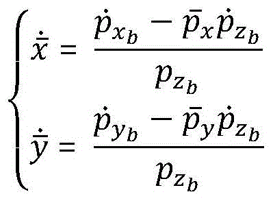
综上所述,对于地面点p,图像点为


将上式写为Write the above formula as

如果有M个可求光流的图像点,有If there are M image points for which optical flow can be obtained, we have

令

式中,


因此,基于光流传感器的测速模型可以表示为:Therefore, the speed measurement model based on the optical flow sensor can be expressed as:

式中ncam为摄像头的测量噪声。基于运动模型
无人机三级控制过程UAV three-level control process
所述飞行控制器基于组合位姿信息,实现无人机三级闭环控制,第一级为姿态控制(转向 方式),第二级为位置控制(升降方式),第三级为传感器控制(监测任务)。The flight controller realizes three-level closed-loop control of the UAV based on the combined position and attitude information. The first level is attitude control (steering mode), the second level is position control (lifting mode), and the third level is sensor control (monitoring). Task).
基于地面站传输的计划任务、实时规划任何和设备遥控管理指令,实现机载测控设备的 状态监测调整、遥测数据收集控制以及飞行性能管理等监测控制功能。Based on the planned tasks transmitted by the ground station, real-time planning of any and equipment remote control management instructions, the monitoring and control functions such as state monitoring and adjustment of airborne measurement and control equipment, telemetry data collection and control, and flight performance management are realized.
第一级:飞行控制器所连接的微惯性导航系统,基于姿态扩展卡尔曼滤波对加速度计进 行非重力加速度分离,然后对加速度计进行一次和二次积分获取含有误差的角度、角速度, 同时加速度/磁力计对俯仰角、滚动角和偏航角进行矫正。The first stage: the micro-inertial navigation system connected to the flight controller, the accelerometer is separated from the non-gravitational acceleration based on the attitude extended Kalman filter, and then the accelerometer is integrated once and twice to obtain the angle and angular velocity with errors, and the acceleration /Magnetometer corrects pitch, roll, and yaw.
第二级:飞行控制器所连接的气压计、光流传感器、UWB定位标签,基于组合位置深组 合改进滤波算法,修正由加速度计积分带来的速度、位置估计误差,获得无人机的三维坐标、 角度和速度。The second level: the barometer, optical flow sensor, and UWB positioning tag connected to the flight controller, based on the combined position depth combination to improve the filtering algorithm, correct the speed and position estimation errors caused by the accelerometer integration, and obtain the three-dimensional UAV. Coordinates, angles and speeds.
第三级:飞行控制器通过所连的无线通信终端接受地面站传输的计划任务,和姿态控制 器通过控制分配器控制电机和无人机的飞行状态,调整机载监测传感器任务流程。The third level: The flight controller accepts the planned tasks transmitted by the ground station through the connected wireless communication terminal, and the attitude controller controls the flight status of the motor and the UAV through the control distributor, and adjusts the task flow of the onboard monitoring sensor.
所述OF避障模块安装在无人机顶部,进行无人机顶部到桥梁底部的短距离测距和特征获 取,在桥梁下方探测到障碍物后,使无人机采取规避动作(定点控制、上升下降、地下跟随方 式),从而实现无人机在桥梁下方的防碰撞(避障)功能;所述OF模块利用图像序列中像素 的时域变化以及相邻帧的差分,来测量其在桥梁底部成像平面上像素小运动的瞬时差异,从 而估计平面方向的位移变化量、变化率和方向,实现无人机在桥梁下方的悬停自稳、定向飞 行、定速飞行等。The OF obstacle avoidance module is installed on the top of the UAV, and performs short-distance ranging and feature acquisition from the top of the UAV to the bottom of the bridge. After detecting obstacles under the bridge, the UAV takes evasive actions (fixed-point control, Ascending, descending, and underground following methods), so as to realize the anti-collision (obstacle avoidance) function of the UAV under the bridge; the OF module uses the time domain change of the pixels in the image sequence and the difference between adjacent frames to measure its position on the bridge. The instantaneous difference of the small motion of the pixels on the bottom imaging plane can estimate the displacement change, rate and direction of the plane direction, and realize the hovering self-stabilization, directional flight, and constant speed flight of the UAV under the bridge.
所述的机载监测模块,与无人机飞行控制器连接,包括机载环境监测传感器、视觉监测 传感器和雷达建模传感器。所述的环境监测传感器包括但不限于空速计、温湿计和气体传感 器,所述的视觉监测传感器包括高清摄像机或红外摄像机,所述的雷达建模传感器包括合成 孔径雷达(InSAR)、高光谱成像仪、微波雷达;所述的机载监测模块得到的信息通过机载无 线通信终端实时传输至地面站控制系统。The airborne monitoring module is connected with the UAV flight controller, and includes airborne environment monitoring sensors, visual monitoring sensors and radar modeling sensors. The environmental monitoring sensors include but are not limited to airspeed meters, temperature and humidity meters and gas sensors, the visual monitoring sensors include high-definition cameras or infrared cameras, and the radar modeling sensors include synthetic aperture radar (InSAR), high-resolution Spectral imager, microwave radar; the information obtained by the airborne monitoring module is transmitted to the ground station control system in real time through the airborne wireless communication terminal.
飞行控制器所连接的微惯性导航系统,基于姿态扩展卡尔曼滤波获得无人机的角度、角 速度,加速度/磁力计同时对俯仰角、滚动角和偏航角进行矫正。根据已知的机载雷达的测距 结果d0(无论正负)和桥梁的3D模型,可以得到雷达与病害位置连线与竖直方向的夹角为θ0, 连线在Oexeyeze水平平面投影与x轴夹角θ1。The micro-inertial navigation system connected to the flight controller obtains the angle and angular velocity of the UAV based on the attitude extended Kalman filter, and the accelerometer/magnetometer simultaneously corrects the pitch angle, roll angle and yaw angle. According to the known airborne radar ranging results d 0 (regardless of positive or negative) and the 3D model of the bridge, it can be obtained that the angle between the line connecting the radar and the disease location and the vertical direction is θ 0 , and the line is at O e x e The angle θ 1 between the horizontal plane projection of y e z e and the x-axis.
即得到病害坐标为:(xe+d0sinθ0cosθ1,ye+d0sinθ0sinθ1,ze+Δh+d0cosθ0)。That is, the disease coordinates are obtained as: (x e +d 0 sinθ 0 cosθ 1 , y e +d 0 sinθ 0 sinθ 1 , z e +Δh+d 0 cosθ 0 ).
机载无线通信终端包括数据传输模块、图像传输模块、遥控器接收器和UWB标签地面无 线基础设施包括对应机载通信模块的数据传输模块、图像传输模块、遥控发射器和UWB基站。 数据传输模块将无人机的实时状态数据传输至地面站控制系统,也可将地面站的操作指令实 时发送到无人机端。图像传输模块可以传输图像或视频,为避开干扰,工作频率选择5.8GHz, 并搭载高增益三叶草天线,其具有圆极化特点,以保证无人机在不同的姿态下实现稳定发射 信号。地面端使用两轴(俯仰轴、水平轴)伺服驱动的高增益定向跟踪天线,无人机实时传回 地面的水平、垂直位置信息与地面段所在的位置信息进行地理几何运算,得到地面端天线指 向无人机所需的俯仰角与水平角,通过USB数据口驱动伺服装置,实现天线实时对准无人机, 进而达到远距离实时视频传输的效果。数据和图像的传输通过对应的发射/接收机与地面站建 立链路,地面站再接入网络通信;从而实现数据的机载、地面站、服务器的多层次分布式/ 集中式数据传输和计算。The airborne wireless communication terminal includes a data transmission module, an image transmission module, a remote control receiver and a UWB tag. The ground wireless infrastructure includes a data transmission module, an image transmission module, a remote control transmitter and a UWB base station corresponding to the airborne communication module. The data transmission module transmits the real-time status data of the UAV to the ground station control system, and can also send the operation instructions of the ground station to the UAV terminal in real time. The image transmission module can transmit images or videos. In order to avoid interference, the working frequency is 5.8GHz, and it is equipped with a high-gain clover antenna, which has the characteristics of circular polarization to ensure that the UAV can transmit signals stably in different attitudes. The ground side uses a two-axis (pitch axis, horizontal axis) servo-driven high-gain directional tracking antenna, and the UAV transmits the horizontal and vertical position information of the ground and the position information of the ground segment in real time to perform geo-geometric operations to obtain the ground-side antenna. Point to the pitch angle and horizontal angle required by the drone, drive the servo device through the USB data port, and realize the real-time alignment of the antenna to the drone, thereby achieving the effect of long-distance real-time video transmission. The transmission of data and images establishes a link with the ground station through the corresponding transmitter/receiver, and the ground station is then connected to the network for communication; thus realizing the multi-level distributed/centralized data transmission and calculation of the airborne, ground station, and server data. .
地面站规划控制系统通过连接对应的机载无线通信终端以及地面无线基础设施,可以集 中采集的机载传感器数据,以及基于控制律解算地面站任务(飞行模式、航线规划、感知控 制)的控制要求,形成控制指令和参数,将控制指令和控制参数传输到无人机飞行控制器, 从而执行动作、标定航迹及向操作员提供规划辅助;地面站控制系统基于服务器端多源监测 数据处理可实现不同监测应用,如基于图像的桥梁裂缝特征识别和受力模式分析、基于序列 影像数据的桥梁可视化、基于空速计和温湿度计的桥梁环境分析、基于雷达的桥梁三维建模。The ground station planning and control system can centrally collect the airborne sensor data by connecting the corresponding airborne wireless communication terminals and ground wireless infrastructure, and solve the control of the ground station tasks (flight mode, route planning, perception control) based on the control law requirements, form control instructions and parameters, and transmit the control instructions and control parameters to the UAV flight controller, so as to perform actions, calibrate the track and provide planning assistance to the operator; the ground station control system is based on server-side multi-source monitoring data processing Different monitoring applications can be realized, such as image-based bridge crack feature identification and force pattern analysis, bridge visualization based on sequence image data, bridge environment analysis based on airspeed and temperature and humidity meters, and radar-based bridge 3D modeling.
本项目无人机地面站系统主要分两种模式:(1)基于PC端地面站开发,无人机飞行控 制信息与监控系统信息都呈现在地面站监测平台里;(2)基于移动终端的地面站;移动端的 APP中(手机或其他移动终端)完成主要数据监测功能,移动端APP支持Andriod4.2.2+和 IOS 8.0+两种平台。地面站软件可以根据实际项目任务规划无人机的飞行计划,在飞行过程 中可以实时显示无人机的状态,包括姿态、方位、速度、电量、任务等信息,如图5。The UAV ground station system of this project is mainly divided into two modes: (1) Based on PC-side ground station development, UAV flight control information and monitoring system information are presented in the ground station monitoring platform; (2) Based on mobile terminal Ground station; the main data monitoring function is completed in the mobile APP (mobile phone or other mobile terminal), and the mobile APP supports both Android 4.2.2+ and IOS 8.0+ platforms. The ground station software can plan the flight plan of the UAV according to the actual project task, and can display the status of the UAV in real time during the flight, including information such as attitude, orientation, speed, power, and mission, as shown in Figure 5.
实施例1:检测桥梁底部裂缝和螺栓脱落点Example 1: Detecting cracks at the bottom of bridges and bolt-off points
下面结合附图对本发明作更进一步的说明。系统依次按照以下步骤检测桥梁底部螺栓状 况:The present invention will be further described below in conjunction with the accompanying drawings. The system checks the condition of the bolts at the bottom of the bridge according to the following steps in sequence:
步骤1,把四个UWB基站用碳纤杆固定在桥两侧,并保证无人机在四个定位锚点的范围 内飞行。在地面站软件中预设四个基站的位置坐标。Step 1. Fix the four UWB base stations on both sides of the bridge with carbon fiber poles, and ensure that the drone flies within the range of the four positioning anchor points. The position coordinates of the four base stations are preset in the ground station software.
步骤2,根据光线明暗判断,选择在无人机上放置高清摄像机。为检测桥梁底部螺栓状 况,选择把高清摄像机和雷达上置。Step 2, according to the light and shade judgment, choose to place a high-definition camera on the drone. In order to detect the condition of the bolts at the bottom of the bridge, the high-definition camera and radar were selected.
步骤3,检查无人机飞行平台各模块工作状态。检查无误后,试飞开始实验。Step 3: Check the working status of each module of the UAV flight platform. After checking that everything is correct, the test flight begins.
步骤4,试飞实验无人机起降、悬停等基本功能,无误后通过地面站软件为无人机规划 路线。Step 4: Test the basic functions of the drone such as take-off and landing, hovering, etc., and plan the route for the drone through the ground station software after correct.
步骤5,无人机按照既定路线航行,通过雷达测距使无人机与桥梁底部保持相同距离航 行。Step 5, the UAV sails according to the established route, and the UAV is kept at the same distance from the bottom of the bridge through radar ranging.
步骤6,远程控制无人机对桥梁底部进行拍照或录像,并实时把图像信息传输回地面控 制平台。Step 6: Remotely control the drone to take pictures or videos of the bottom of the bridge, and transmit the image information back to the ground control platform in real time.
步骤7,基于形态学进行图像或视频处理,结合已知的桥梁模型,判断有无裂缝存在。 具体过程:In step 7, image or video processing is performed based on the morphology, and the existence of cracks is judged in combination with the known bridge model. Specific process:
(1)多结构中值滤波将形态学中的结构元素引入到中值滤波中来,采用4种形状的3X3结构元素对原始灰度图像进行依次滤波处理。由于采用了多种结构元素,因而可以对多种噪声进行有效地滤除。(1) Multi-structure median filter The morphological structuring elements are introduced into the median filter, and 3×3 structuring elements of 4 shapes are used to sequentially filter the original grayscale image. Due to the use of various structural elements, various noises can be effectively filtered out.
(2)形态学边缘检测算法与空域梯度算子相比较,用对称结构元素得到的形态学梯度受 边缘方向的影响最小,因此将形态学梯度边缘检测算法应用到桥梁裂缝检测当中,能得到理 想的裂缝边缘特性。(2) Comparing the morphological edge detection algorithm with the spatial gradient operator, the morphological gradient obtained by using symmetric structural elements is least affected by the edge direction. Therefore, the morphological gradient edge detection algorithm is applied to bridge crack detection and can obtain ideal crack edge properties.
(3)裂缝计算对裂缝的长度和宽度的计算,先需要对裂缝进行细化,得到裂缝的骨架, 并求出各段骨架的斜率,再通过计数的方式便可得到裂缝的长度和宽度,进一步评估裂缝对 整个桥梁结构造成的病害。(3) Crack calculation For the calculation of the length and width of the crack, it is necessary to refine the crack first to obtain the skeleton of the crack, and obtain the slope of each skeleton, and then the length and width of the crack can be obtained by counting. Further assess the damage caused by cracks to the entire bridge structure.
(4)结合桥梁结构和螺栓特征,采用原始图像数据发现对应的螺栓脱落点,对脱落点进 行识别记录并形成最终报告。(4) Combined with the bridge structure and bolt characteristics, the corresponding bolt shedding points are found by using the original image data, and the shedding points are identified and recorded, and a final report is formed.
步骤8,数据处理软件结合拍摄包含裂缝和脱落螺栓的视频或图像及无人机的位置、姿 态等信息,按照图4所示的坐标转换图,计算裂缝的具体位置。In step 8, the data processing software calculates the specific position of the crack according to the coordinate conversion diagram shown in Figure 4 in combination with the video or image including the crack and the falling bolt and the position, attitude and other information of the drone.
Claims (5)
Priority Applications (1)
| Application Number | Priority Date | Filing Date | Title |
|---|---|---|---|
| CN201910206658.0A CN109911188B (en) | 2019-03-18 | 2019-03-18 | Bridge detection UAV system for non-satellite navigation and positioning environment |
Applications Claiming Priority (1)
| Application Number | Priority Date | Filing Date | Title |
|---|---|---|---|
| CN201910206658.0A CN109911188B (en) | 2019-03-18 | 2019-03-18 | Bridge detection UAV system for non-satellite navigation and positioning environment |
Publications (2)
| Publication Number | Publication Date |
|---|---|
| CN109911188A CN109911188A (en) | 2019-06-21 |
| CN109911188B true CN109911188B (en) | 2022-02-11 |
Family
ID=66965561
Family Applications (1)
| Application Number | Title | Priority Date | Filing Date |
|---|---|---|---|
| CN201910206658.0A Active CN109911188B (en) | 2019-03-18 | 2019-03-18 | Bridge detection UAV system for non-satellite navigation and positioning environment |
Country Status (1)
| Country | Link |
|---|---|
| CN (1) | CN109911188B (en) |
Families Citing this family (24)
| Publication number | Priority date | Publication date | Assignee | Title |
|---|---|---|---|---|
| CN110275195A (en) * | 2019-07-03 | 2019-09-24 | 广西科技大学 | A Precise Positioning System for Unmanned Aerial Vehicles in Bridge Environment |
| CN110470226B (en) * | 2019-07-10 | 2021-05-28 | 广东工业大学 | A Displacement Measurement Method of Bridge Structure Based on UAV System |
| CN110441314A (en) * | 2019-07-30 | 2019-11-12 | 南京华智大为科技有限责任公司 | Bridge beam slab bottom surface inspection system based on unmanned plane automatic scanning |
| CN110515071A (en) * | 2019-08-24 | 2019-11-29 | 四川大学 | GPS-less Integrated Navigation Method Based on UWB Radar and Optical Flow Sensor |
| CN110601745B (en) * | 2019-09-18 | 2021-08-20 | 无锡睿思凯科技股份有限公司 | A UAV communication method with communication/ranging dual system |
| CN111983660A (en) * | 2020-07-06 | 2020-11-24 | 天津大学 | Quadrotor UAV Positioning System and Method in GNSS Denied Environment |
| CN112344930A (en) * | 2020-11-27 | 2021-02-09 | 上海工程技术大学 | Indoor positioning navigation system for unmanned aerial vehicle |
| CN113766416A (en) * | 2020-12-02 | 2021-12-07 | 北京京东乾石科技有限公司 | Unmanned aerial vehicle positioning method and device and storage medium |
| CN113821044A (en) * | 2021-07-06 | 2021-12-21 | 西北工业大学 | Autonomous Navigation and Stability Control Method for Bridge Detection UAV Based on Reinforcement Learning |
| CN113340405B (en) * | 2021-07-09 | 2023-03-17 | 中铁七局集团有限公司 | Bridge vibration mode measuring method, device and system |
| CN113359809B (en) * | 2021-07-23 | 2022-11-11 | 西北工业大学 | Bridge detection unmanned aerial vehicle autonomous positioning method based on RBFNN assistance |
| CN113552904A (en) * | 2021-08-18 | 2021-10-26 | 上海同陆云交通科技有限公司 | Improved bridge bottom detection system for unmanned aerial vehicle |
| CN114138013B (en) * | 2021-11-19 | 2025-03-25 | 武汉珈鹰智能科技有限公司 | A method, device, equipment and storage medium for flying an unmanned aerial vehicle at a constant altitude |
| CN113928563A (en) * | 2021-11-19 | 2022-01-14 | 武汉珈鹰智能科技有限公司 | A drone used to detect the bottom of bridges |
| CN114419109B (en) * | 2022-03-29 | 2022-06-24 | 中航金城无人系统有限公司 | Aircraft positioning method based on visual and barometric information fusion |
| CN115077655B (en) * | 2022-06-13 | 2025-05-09 | 中国极地研究中心(中国极地研究所) | A system and method for measuring water capacity of polar lakes |
| CN115131316A (en) * | 2022-06-29 | 2022-09-30 | 南京航空航天大学 | Concrete bridge deck pavement bonding layer damage detection method based on machine vision |
| CN116643234B (en) * | 2023-04-28 | 2025-10-03 | 中国民航大学 | A UAV cluster positioning system based on DW1000 |
| CN116295020B (en) * | 2023-05-22 | 2023-08-08 | 山东高速工程检测有限公司 | Method and device for locating bridge defects |
| CN116560383A (en) * | 2023-06-08 | 2023-08-08 | 云南电网有限责任公司怒江供电局 | An unmanned aerial vehicle mobile terminal control device |
| CN117032276B (en) * | 2023-07-04 | 2024-06-25 | 长沙理工大学 | Bridge detection method and system based on binocular vision and inertial navigation fusion unmanned aerial vehicle |
| CN117705186B (en) * | 2023-12-11 | 2024-07-19 | 利德世普科技有限公司 | Iron tower state monitoring system |
| CN120803013B (en) * | 2025-09-16 | 2025-11-28 | 时代天海科技有限公司 | Attitude control system for short wave satellite |
| CN120853327B (en) * | 2025-09-25 | 2026-01-06 | 福建融茂水利水电工程有限公司 | A Construction Safety Management Method Based on Excavator Perspective Image Fusion |
Family Cites Families (4)
| Publication number | Priority date | Publication date | Assignee | Title |
|---|---|---|---|---|
| CN101598557B (en) * | 2009-07-15 | 2012-05-23 | 北京航空航天大学 | Integrated navigation system applied to pilotless aircraft |
| US11467274B2 (en) * | 2015-09-29 | 2022-10-11 | Tyco Fire & Security Gmbh | Search and rescue UAV system and method |
| WO2018156284A1 (en) * | 2017-02-21 | 2018-08-30 | Walmart Apollo, Llc | Systems and methods for delivering merchandise using unmanned aerial vehicles |
| CN109445449B (en) * | 2018-11-29 | 2019-10-22 | 浙江大学 | A high subsonic UAV ultra-low altitude flight control system and method |
-
2019
- 2019-03-18 CN CN201910206658.0A patent/CN109911188B/en active Active
Also Published As
| Publication number | Publication date |
|---|---|
| CN109911188A (en) | 2019-06-21 |
Similar Documents
| Publication | Publication Date | Title |
|---|---|---|
| CN109911188B (en) | Bridge detection UAV system for non-satellite navigation and positioning environment | |
| CN110262546B (en) | A kind of tunnel intelligent drone inspection method | |
| US11218689B2 (en) | Methods and systems for selective sensor fusion | |
| CN113124856B (en) | Visual inertia tight coupling odometer based on UWB (ultra wide band) online anchor point and metering method | |
| CN108306217B (en) | Intelligent autonomous overhead high-voltage line wire flying inspection system and method | |
| CN105628026B (en) | A kind of positioning and orientation method and system of mobile object | |
| CN101201248B (en) | Aerial close-range photography displacement measurement system and method based on UAV | |
| CN111426320B (en) | Vehicle autonomous navigation method based on image matching/inertial navigation/milemeter | |
| CN106526551B (en) | A kind of radar antenna dynamic performance testing system and method | |
| CN102353377B (en) | High altitude long endurance unmanned aerial vehicle integrated navigation system and navigating and positioning method thereof | |
| CN112394382B (en) | Low-speed small target tracking device and method capable of resisting long-term shielding | |
| Strydom et al. | Visual odometry: autonomous uav navigation using optic flow and stereo | |
| CN102508493B (en) | Flight control method for small unmanned aerial vehicle | |
| CN101109640A (en) | Vision-based autonomous landing navigation system for unmanned aircraft | |
| CN104843176A (en) | Unmanned-gyroplane system used for automatic-inspection of bridges and tunnels and navigation method | |
| CN105182992A (en) | Unmanned aerial vehicle control method and device | |
| RU195749U1 (en) | Intelligent vision system for an unmanned aerial vehicle for solving navigation problems, building a three-dimensional map of the surrounding space and obstacles, and autonomous patrolling | |
| CN103983263A (en) | Inertia/visual integrated navigation method adopting iterated extended Kalman filter and neural network | |
| CN113156998B (en) | Control method of unmanned aerial vehicle flight control system | |
| CN103353297A (en) | Airborne photoelectric measurement apparatus of dimensions and spacing of electric transmission line and target, and method thereof | |
| CN102175882B (en) | Natural-landmark-based unmanned helicopter visual speed measurement method | |
| US20250306208A1 (en) | Laser slam system for slope compensation by using imu and implementation method thereof | |
| CN102788580A (en) | Flight path synthetic method in unmanned aerial vehicle visual navigation | |
| CN105045276A (en) | Method and apparatus for controlling flight of unmanned plane | |
| CN119987412A (en) | An autonomous flight and inspection system for unmanned aerial vehicles based on multi-sensor fusion technology |
Legal Events
| Date | Code | Title | Description |
|---|---|---|---|
| PB01 | Publication | ||
| PB01 | Publication | ||
| SE01 | Entry into force of request for substantive examination | ||
| SE01 | Entry into force of request for substantive examination | ||
| GR01 | Patent grant | ||
| GR01 | Patent grant |