[go: up one dir, main page]

CN109862925B - One-piece volute - Google Patents

One-piece volute Download PDF

Info

Publication number
CN109862925B
CN109862925B CN201780065651.0A CN201780065651A CN109862925B CN 109862925 B CN109862925 B CN 109862925B CN 201780065651 A CN201780065651 A CN 201780065651A CN 109862925 B CN109862925 B CN 109862925B
Authority
CN
China
Prior art keywords
axis
pump housing
inlet chamber
radius
wall
Prior art date
Legal status (The legal status is an assumption and is not a legal conclusion. Google has not performed a legal analysis and makes no representation as to the accuracy of the status listed.)
Expired - Fee Related
Application number
CN201780065651.0A
Other languages
Chinese (zh)
Other versions
CN109862925A (en
Inventor
C·R·山姆巴弗
M·E·塔斯金
Current Assignee (The listed assignees may be inaccurate. Google has not performed a legal analysis and makes no representation or warranty as to the accuracy of the list.)
Heart Instrument Co ltd
Original Assignee
Heart Instrument Co ltd
Priority date (The priority date is an assumption and is not a legal conclusion. Google has not performed a legal analysis and makes no representation as to the accuracy of the date listed.)
Filing date
Publication date
Application filed by Heart Instrument Co ltd filed Critical Heart Instrument Co ltd
Publication of CN109862925A publication Critical patent/CN109862925A/en
Application granted granted Critical
Publication of CN109862925B publication Critical patent/CN109862925B/en
Expired - Fee Related legal-status Critical Current
Anticipated expiration legal-status Critical

Links

Images

Classifications

    • AHUMAN NECESSITIES
    • A61MEDICAL OR VETERINARY SCIENCE; HYGIENE
    • A61MDEVICES FOR INTRODUCING MEDIA INTO, OR ONTO, THE BODY; DEVICES FOR TRANSDUCING BODY MEDIA OR FOR TAKING MEDIA FROM THE BODY; DEVICES FOR PRODUCING OR ENDING SLEEP OR STUPOR
    • A61M60/00Blood pumps; Devices for mechanical circulatory actuation; Balloon pumps for circulatory assistance
    • A61M60/40Details relating to driving
    • A61M60/403Details relating to driving for non-positive displacement blood pumps
    • A61M60/419Details relating to driving for non-positive displacement blood pumps the force acting on the blood contacting member being permanent magnetic, e.g. from a rotating magnetic coupling between driving and driven magnets
    • AHUMAN NECESSITIES
    • A61MEDICAL OR VETERINARY SCIENCE; HYGIENE
    • A61MDEVICES FOR INTRODUCING MEDIA INTO, OR ONTO, THE BODY; DEVICES FOR TRANSDUCING BODY MEDIA OR FOR TAKING MEDIA FROM THE BODY; DEVICES FOR PRODUCING OR ENDING SLEEP OR STUPOR
    • A61M60/00Blood pumps; Devices for mechanical circulatory actuation; Balloon pumps for circulatory assistance
    • A61M60/10Location thereof with respect to the patient's body
    • A61M60/122Implantable pumps or pumping devices, i.e. the blood being pumped inside the patient's body
    • A61M60/165Implantable pumps or pumping devices, i.e. the blood being pumped inside the patient's body implantable in, on, or around the heart
    • A61M60/178Implantable pumps or pumping devices, i.e. the blood being pumped inside the patient's body implantable in, on, or around the heart drawing blood from a ventricle and returning the blood to the arterial system via a cannula external to the ventricle, e.g. left or right ventricular assist devices
    • AHUMAN NECESSITIES
    • A61MEDICAL OR VETERINARY SCIENCE; HYGIENE
    • A61MDEVICES FOR INTRODUCING MEDIA INTO, OR ONTO, THE BODY; DEVICES FOR TRANSDUCING BODY MEDIA OR FOR TAKING MEDIA FROM THE BODY; DEVICES FOR PRODUCING OR ENDING SLEEP OR STUPOR
    • A61M60/00Blood pumps; Devices for mechanical circulatory actuation; Balloon pumps for circulatory assistance
    • A61M60/10Location thereof with respect to the patient's body
    • A61M60/122Implantable pumps or pumping devices, i.e. the blood being pumped inside the patient's body
    • A61M60/126Implantable pumps or pumping devices, i.e. the blood being pumped inside the patient's body implantable via, into, inside, in line, branching on, or around a blood vessel
    • A61M60/148Implantable pumps or pumping devices, i.e. the blood being pumped inside the patient's body implantable via, into, inside, in line, branching on, or around a blood vessel in line with a blood vessel using resection or like techniques, e.g. permanent endovascular heart assist devices
    • AHUMAN NECESSITIES
    • A61MEDICAL OR VETERINARY SCIENCE; HYGIENE
    • A61MDEVICES FOR INTRODUCING MEDIA INTO, OR ONTO, THE BODY; DEVICES FOR TRANSDUCING BODY MEDIA OR FOR TAKING MEDIA FROM THE BODY; DEVICES FOR PRODUCING OR ENDING SLEEP OR STUPOR
    • A61M60/00Blood pumps; Devices for mechanical circulatory actuation; Balloon pumps for circulatory assistance
    • A61M60/20Type thereof
    • A61M60/205Non-positive displacement blood pumps
    • A61M60/216Non-positive displacement blood pumps including a rotating member acting on the blood, e.g. impeller
    • A61M60/226Non-positive displacement blood pumps including a rotating member acting on the blood, e.g. impeller the blood flow through the rotating member having mainly radial components
    • A61M60/232Centrifugal pumps
    • AHUMAN NECESSITIES
    • A61MEDICAL OR VETERINARY SCIENCE; HYGIENE
    • A61MDEVICES FOR INTRODUCING MEDIA INTO, OR ONTO, THE BODY; DEVICES FOR TRANSDUCING BODY MEDIA OR FOR TAKING MEDIA FROM THE BODY; DEVICES FOR PRODUCING OR ENDING SLEEP OR STUPOR
    • A61M60/00Blood pumps; Devices for mechanical circulatory actuation; Balloon pumps for circulatory assistance
    • A61M60/40Details relating to driving
    • A61M60/403Details relating to driving for non-positive displacement blood pumps
    • A61M60/422Details relating to driving for non-positive displacement blood pumps the force acting on the blood contacting member being electromagnetic, e.g. using canned motor pumps
    • AHUMAN NECESSITIES
    • A61MEDICAL OR VETERINARY SCIENCE; HYGIENE
    • A61MDEVICES FOR INTRODUCING MEDIA INTO, OR ONTO, THE BODY; DEVICES FOR TRANSDUCING BODY MEDIA OR FOR TAKING MEDIA FROM THE BODY; DEVICES FOR PRODUCING OR ENDING SLEEP OR STUPOR
    • A61M60/00Blood pumps; Devices for mechanical circulatory actuation; Balloon pumps for circulatory assistance
    • A61M60/80Constructional details other than related to driving
    • A61M60/802Constructional details other than related to driving of non-positive displacement blood pumps
    • A61M60/81Pump housings
    • A61M60/814Volutes
    • AHUMAN NECESSITIES
    • A61MEDICAL OR VETERINARY SCIENCE; HYGIENE
    • A61MDEVICES FOR INTRODUCING MEDIA INTO, OR ONTO, THE BODY; DEVICES FOR TRANSDUCING BODY MEDIA OR FOR TAKING MEDIA FROM THE BODY; DEVICES FOR PRODUCING OR ENDING SLEEP OR STUPOR
    • A61M60/00Blood pumps; Devices for mechanical circulatory actuation; Balloon pumps for circulatory assistance
    • A61M60/80Constructional details other than related to driving
    • A61M60/802Constructional details other than related to driving of non-positive displacement blood pumps
    • A61M60/818Bearings
    • A61M60/824Hydrodynamic or fluid film bearings
    • BPERFORMING OPERATIONS; TRANSPORTING
    • B33ADDITIVE MANUFACTURING TECHNOLOGY
    • B33YADDITIVE MANUFACTURING, i.e. MANUFACTURING OF THREE-DIMENSIONAL [3-D] OBJECTS BY ADDITIVE DEPOSITION, ADDITIVE AGGLOMERATION OR ADDITIVE LAYERING, e.g. BY 3-D PRINTING, STEREOLITHOGRAPHY OR SELECTIVE LASER SINTERING
    • B33Y80/00Products made by additive manufacturing
    • AHUMAN NECESSITIES
    • A61MEDICAL OR VETERINARY SCIENCE; HYGIENE
    • A61MDEVICES FOR INTRODUCING MEDIA INTO, OR ONTO, THE BODY; DEVICES FOR TRANSDUCING BODY MEDIA OR FOR TAKING MEDIA FROM THE BODY; DEVICES FOR PRODUCING OR ENDING SLEEP OR STUPOR
    • A61M2207/00Methods of manufacture, assembly or production
    • BPERFORMING OPERATIONS; TRANSPORTING
    • B29WORKING OF PLASTICS; WORKING OF SUBSTANCES IN A PLASTIC STATE IN GENERAL
    • B29CSHAPING OR JOINING OF PLASTICS; SHAPING OF MATERIAL IN A PLASTIC STATE, NOT OTHERWISE PROVIDED FOR; AFTER-TREATMENT OF THE SHAPED PRODUCTS, e.g. REPAIRING
    • B29C64/00Additive manufacturing, i.e. manufacturing of three-dimensional [3D] objects by additive deposition, additive agglomeration or additive layering, e.g. by 3D printing, stereolithography or selective laser sintering
    • B29C64/10Processes of additive manufacturing
    • B29C64/106Processes of additive manufacturing using only liquids or viscous materials, e.g. depositing a continuous bead of viscous material
    • B29C64/124Processes of additive manufacturing using only liquids or viscous materials, e.g. depositing a continuous bead of viscous material using layers of liquid which are selectively solidified
    • B29C64/129Processes of additive manufacturing using only liquids or viscous materials, e.g. depositing a continuous bead of viscous material using layers of liquid which are selectively solidified characterised by the energy source therefor, e.g. by global irradiation combined with a mask
    • B29C64/135Processes of additive manufacturing using only liquids or viscous materials, e.g. depositing a continuous bead of viscous material using layers of liquid which are selectively solidified characterised by the energy source therefor, e.g. by global irradiation combined with a mask the energy source being concentrated, e.g. scanning lasers or focused light sources
    • BPERFORMING OPERATIONS; TRANSPORTING
    • B29WORKING OF PLASTICS; WORKING OF SUBSTANCES IN A PLASTIC STATE IN GENERAL
    • B29KINDEXING SCHEME ASSOCIATED WITH SUBCLASSES B29B, B29C OR B29D, RELATING TO MOULDING MATERIALS OR TO MATERIALS FOR MOULDS, REINFORCEMENTS, FILLERS OR PREFORMED PARTS, e.g. INSERTS
    • B29K2995/00Properties of moulding materials, reinforcements, fillers, preformed parts or moulds
    • B29K2995/0037Other properties
    • B29K2995/0056Biocompatible, e.g. biopolymers or bioelastomers
    • BPERFORMING OPERATIONS; TRANSPORTING
    • B29WORKING OF PLASTICS; WORKING OF SUBSTANCES IN A PLASTIC STATE IN GENERAL
    • B29LINDEXING SCHEME ASSOCIATED WITH SUBCLASS B29C, RELATING TO PARTICULAR ARTICLES
    • B29L2031/00Other particular articles
    • B29L2031/753Medical equipment; Accessories therefor
    • BPERFORMING OPERATIONS; TRANSPORTING
    • B33ADDITIVE MANUFACTURING TECHNOLOGY
    • B33YADDITIVE MANUFACTURING, i.e. MANUFACTURING OF THREE-DIMENSIONAL [3-D] OBJECTS BY ADDITIVE DEPOSITION, ADDITIVE AGGLOMERATION OR ADDITIVE LAYERING, e.g. BY 3-D PRINTING, STEREOLITHOGRAPHY OR SELECTIVE LASER SINTERING
    • B33Y10/00Processes of additive manufacturing

Landscapes

  • Health & Medical Sciences (AREA)
  • Heart & Thoracic Surgery (AREA)
  • Engineering & Computer Science (AREA)
  • Cardiology (AREA)
  • Hematology (AREA)
  • General Health & Medical Sciences (AREA)
  • Veterinary Medicine (AREA)
  • Mechanical Engineering (AREA)
  • Anesthesiology (AREA)
  • Biomedical Technology (AREA)
  • Public Health (AREA)
  • Life Sciences & Earth Sciences (AREA)
  • Animal Behavior & Ethology (AREA)
  • Physics & Mathematics (AREA)
  • Fluid Mechanics (AREA)
  • Vascular Medicine (AREA)
  • Materials Engineering (AREA)
  • Chemical & Material Sciences (AREA)
  • Manufacturing & Machinery (AREA)
  • External Artificial Organs (AREA)
  • Structures Of Non-Positive Displacement Pumps (AREA)

Abstract

一种血泵壳体包括整件式主体。该整件式主体限定有入口腔室,该入口腔室沿着第一轴线延伸并具有垂直于第一轴线的第一半径。过渡腔室连接于入口腔室并且具有沿围绕第一轴线的周向延伸的壁,该壁具有距第一轴线的大半径和小半径,大半径大于第一半径。柱沿着第一轴线从过渡腔室延伸到入口腔室中,该柱沿绕第一轴线的方向朝向入口腔室渐缩。出口连接于过渡腔室并且沿着横向于第一轴线的第二轴线延伸。

Figure 201780065651

A blood pump housing includes a one-piece body. The one-piece body defines an inlet chamber extending along a first axis and having a first radius perpendicular to the first axis. The transition chamber is connected to the inlet chamber and has a wall extending circumferentially about the first axis, the wall having a large radius from the first axis and a small radius, the large radius being greater than the first radius. A post extends from the transition chamber into the inlet chamber along a first axis, the post tapering toward the inlet chamber in a direction about the first axis. The outlet is connected to the transition chamber and extends along a second axis transverse to the first axis.

Figure 201780065651

Description

Single piece volute
Technical Field
The present invention relates to a pump housing, and in particular to a pump housing for a mechanical circulation support device or "MCSD".
Background
The pump housing serves to collect fluid introduced by the impeller at an upstream location and direct the fluid to an outlet at a downstream location. The fluid flow path in the pump housing is typically designed to convert dynamic energy (velocity) into pressure energy, i.e., to convert pump energy transferred from the impeller into pressure energy.
An improperly sized and/or manufactured housing may account for a significant portion of the overall pump losses. Proper design of the fluid flow path in the pump housing is critical to ensure overall pump performance and to minimize pump energy consumption. This is particularly true for pumps used to assist the pumping action of the heart in MCSDs. Pump housings for MCSDs are typically volute-shaped, wherein the cross section of the volute (flow channel) increases in the circumferential direction of the discharge in order to maintain a constant fluid velocity. The volute flow path is designed to maintain a Constant Angular Momentum (CAM) or a Constant Mean Velocity (CMV).
Pump housings having complex flow channels to achieve the desired flow characteristics have complex internal walls and are not easily manufactured by conventional methods. The pump housing used in MCSD is much smaller than pump housings used in most other applications in order to allow implantation of the MCSD within a patient. The small dimensions of the MCSD pump housings further complicate the efforts to manufacture these pump housings by conventional methods. Pump housings having the dimensions used in MCSDs are typically manufactured in two or more parts that are later attached to one another. This further increases the labor for manufacturing these pump housings.
Disclosure of Invention
The present invention advantageously provides a blood pump housing comprising a one-piece body. The one-piece body defines an inlet chamber extending along a first axis and having a first radius perpendicular to the first axis. The transition chamber is connected to the inlet chamber and has a wall extending in a circumferential direction about the first axis, the wall having a large radius and a small radius from the first axis, the large radius being greater than the first radius. A post extends from the transition chamber into the inlet chamber along a first axis, the post tapering toward the inlet chamber in a direction about the first axis. The outlet is connected to the transition chamber and extends along a second axis transverse to the first axis.
In another aspect of this embodiment, the body comprises a polymer.
In another aspect of this embodiment, the small radius is equal to or greater than the first radius.
In another aspect of this embodiment, the post is tapered.
In another aspect of this embodiment, the outlet includes a closed channel having a first section with a substantially rectangular cross-section transverse to the second axis and communicating with the transition chamber, and a second section with a substantially circular cross-section transverse to the second axis and communicating with the first section.
In another aspect of this embodiment, the first axis is perpendicular to the second axis.
In another aspect of this embodiment, the body includes a first wall surrounding an interior of the inlet chamber over at least a portion of an axial extent of the inlet chamber and a second wall surrounding an exterior of the first wall, the first wall and the second wall defining an annular space.
In another aspect of this embodiment, the inlet chamber is cylindrical.
In another embodiment, the mechanical circulation support device comprises a one-piece body. The one-piece body defines an inlet chamber extending along a first axis and having a first radius perpendicular to the first axis. The transition chamber is connected to the inlet chamber and has a wall extending in a circumferential direction about the first axis, the wall having a large radius and a small radius from the first axis, the large radius being greater than the first radius. A post extends from the transition chamber into the inlet chamber along a first axis, the post tapering toward the inlet chamber in a direction about the first axis. The outlet is connected to the transition chamber and extends along a second axis transverse to the first axis. The housing is connected to the inlet chamber, and the rotor is disposed within the housing and configured to push blood into the inlet chamber.
In another aspect of this embodiment, the post is tapered.
In another aspect of this embodiment, the outlet includes a closed channel having a first section with a substantially rectangular cross-section transverse to the second axis and communicating with the transition chamber, and a second section with a substantially circular cross-section transverse to the second axis and communicating with the first section.
In another aspect of this embodiment, the first axis is perpendicular to the second axis.
In another aspect of this embodiment, the body includes a first wall surrounding an interior of the inlet chamber over at least a portion of an axial extent of the inlet chamber and a second wall surrounding an exterior of the first wall, the first wall and the second wall defining an annular space.
In another aspect of this embodiment, the inlet chamber is cylindrical.
In another embodiment, a method of manufacturing a blood pump housing includes forming a body of a blood pump housing by an additive manufacturing process, the body of the housing being unitary. The one-piece body defines an inlet chamber extending along a first axis and having a first radius perpendicular to the first axis. The transition chamber is connected to the inlet chamber and has a wall extending in a circumferential direction about the first axis, the wall having a large radius and a small radius from the first axis, the large radius being greater than the first radius. A post extends from the transition chamber into the inlet chamber along a first axis, the post tapering toward the inlet chamber in a direction about the first axis. The outlet is connected to the transition chamber and extends along a second axis transverse to the first axis.
In another aspect of this embodiment, the additive manufacturing process comprises stereolithography.
In another aspect of this embodiment, the body of the housing is made of a resin polymer.
In another aspect of this embodiment, the additive manufacturing process comprises fused deposition modeling.
In another aspect of this embodiment, the additive manufacturing process comprises inkjet printing.
In another aspect of this embodiment, the additive manufacturing process includes a powder bed technique.
Drawings
A more complete understanding of the present invention, and the attendant advantages and features thereof, will be more readily understood by reference to the following detailed description when considered in conjunction with the accompanying drawings wherein:
FIG. 1 is a perspective view of a pump housing of an embodiment of the present disclosure;
FIG. 2 is a top view of the pump housing of FIG. 1;
FIG. 3 is a side view of the pump housing of FIG. 1;
FIG. 4 is a cross-sectional view taken along line A-of FIG. 2;
FIG. 5 is a cross-sectional view taken along line B of FIG. 2;
FIG. 6 is a cross-sectional view taken along line C of FIG. 2;
FIG. 7 is a cross-sectional view taken along line D of FIG. 3;
FIG. 8 is a cross-sectional view taken along line E-of FIG. 3;
FIG. 9A is a cross-sectional view of a mechanical circulation support device including the pump housing of FIG. 1; and
fig. 9B is a front view of the mechanical circulation support device of fig. 9A.
Detailed Description
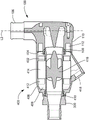
Referring now to the drawings, in which like reference numerals refer to like elements, there is shown in FIGS. 1-8 a pump housing, generally designated 100, in accordance with an embodiment of the present invention. The pump housing 100 has a unitary, i.e., one-piece, body defining an inlet chamber 102, a transition chamber 104, and an outlet 106. The inlet chamber 102 and the transition chamber 104 are connected to each other and are arranged about a first longitudinal axis L1. The outlet 104 extends about a second axis L2, which is L2 perpendicular to the first axis L1. A post 114 (best seen in fig. 4), which may be conical or any shape, extends from the base of the transition chamber 104 into the inlet chamber 102 along the longitudinal axis L1.
As best shown in fig. 3 and 5, the body includes an inner wall 108 defining an upstream portion of the inlet chamber 102 and an inlet port 122 for receiving fluid pumped at the upstream end of the inlet chamber 102. In one configuration, the inlet chamber 102 is substantially cylindrical with a radius R1 measured from the first axis L1 to the inner surface of the wall 108. A pair of O-ring grooves 103 (fig. 5) are provided in the inner surface of wall 108 near inlet port 122. The body also has an outer wall 110, the outer wall 110 being spaced radially outwardly from the inner wall 108 and extending about the axis L1 such that the inner and outer walls define an annular space 112 (fig. 7). As described below, the annular space 112 may be used to house other pump components and/or may facilitate attachment of the pump housing 102 to other pump components.
The transition chamber 104 is located downstream of the inlet chamber 102. The body includes a wall 128 (fig. 5, 6 and 8) extending circumferentially about axis L1 and defining a radial extent of the transition chamber 104. As best shown in fig. 8, the transition chamber 104 provides a volute-shaped flow path. In other words, the radius of the transition chamber 104, measured from the axis L1 to the inner surface of the wall, varies in the circumferential direction. The minimum radius R2 is configured at the tongue 120 at the entrance to the outlet 106. The radius gradually increases in a forward circumferential direction as indicated by arrow 122 in fig. 8 to a maximum radius R3 (fig. 8) adjacent tongue 120. As shown in FIG. 6, radius R5 is greater than radius R4. The swirl flow path is designed to vary the cross-sectional area of the flow path such that the narrowest area (at minimum radius R2) is located at the tongue 120 and the largest cross-sectional area (at maximum radius R3) is located at an azimuthal angle of about 360 degrees in the forward circumferential direction indicated by directional arrow 122 in fig. 8. The forward circumferential direction corresponds to the flow direction of the pumped blood during operation. The increasing cross-sectional area in the flow direction ensures that the static pressure remains constant, which minimizes the radial thrust on the pump impeller. The cross-sectional area of the swirl flow path of the present embodiment is configured based on achieving a Constant Mean Velocity (CMV), and other embodiments may utilize other methods, including utilizing a Constant Angular Momentum (CAM) method to design the swirl flow passage. In this embodiment, the small radius R2 of the transition chamber 104 is slightly larger than the radius R1 of the inlet chamber 102, while the maximum radius R3 is substantially larger than R1. Thus, the body defines a step 129, which step 129 has a surface facing in the downstream direction (towards the bottom of the figures in fig. 5 and 6) at the intersection of the inlet chamber 102 and the transition chamber 104.
The body also includes a base wall 126 that defines an end surface of the transition chamber 104. The end face is substantially planar and perpendicular to the axis L1 of the inlet chamber. The post 114 protrudes upstream from the base wall 126, through the transition chamber 104 and into the inlet chamber 102. The post 114 is in the form of a solid of revolution about axis L1 having a radius that gradually increases in a downstream direction toward the wall 126. In the particular embodiment shown, the post 114 is substantially conical with a rounded tip at its upstream end. As can best be understood with reference to fig. 5 and 6, the end surface defined by the wall 126, the step 129 and the circumferential wall 128 imparts a substantially rectangular cross-sectional shape to the peripheral portion of the transition chamber.
The body also defines a tubular outlet 106 (fig. 2, 4 and 8) in communication with the transition chamber. The tubular outlet includes a section 116 and a section 118, the section 116 having a generally rectangular cross-sectional shape extending from the intersection of the outlet and the transition chamber, the section 118 having a generally circular cross-sectional shape extending from the section 118. The cross-sectional area of section 118 may be greater than the cross-sectional area of section 116 to reduce the discharge velocity. The tongue 120 (fig. 8) represents an edge formed at the intersection of the volute profile of the transition chamber 104 and the tubular outlet 106. The flow below the tongue is directed back into the transition chamber 104, while the flow above the tongue is forced into the outlet 106.
Fig. 9A and 9B illustrate an MCSD incorporating the pump housing 100 discussed above in connection with fig. 1-8. The components of MCSD400 may be substantially as described in U.S. patent nos. 7,972,122; 8,007,254 No; and 8,419,609, the disclosure of which is incorporated herein by reference. MCSD400 may include a tubular inner housing 402, with the tubular inner housing 402 being connected to the upstream opening 122 of housing 100 and sealed to inner wall 108 by an O-ring 402. The inlet fitting 300 is connected to the upstream end of the inner housing 402. As more fully disclosed in U.S. patent application No. 62/270,189, inlet fitting 300 may be removable to allow insertion and placement of the rotor into inner housing 402; the disclosure of this document is incorporated herein by reference.
A generally cylindrical hollow outer shell 408 surrounds the inner shell 402. The outer shell is spaced apart from the inner shell such that the inner and outer shells collectively define an annular space 408 therebetween. The upstream end of the outer housing 406 is sealed to the exterior of the inner housing 402 by a seal, such as an O-ring 410. The downstream end of the housing is sealingly connected to the outer wall 110 of the housing 100. For example, the outer wall 110 may be welded or glued to the housing 406, or a resilient seal such as an O-ring (not shown) may be provided between these elements. The space 112 defined by the outer wall 110 and the inner wall 108 of the housing communicates with a space 408 within the housing 406. A set of electrical coils 412 and a ferromagnetic stator frame 414 are disposed within the space 408. Electrical wiring (not shown) connected to the coil 412 is also disposed within the space 408. The wiring is connected to a cable, commonly referred to as a "drive line" (not shown), which extends through a port 418 in the housing 406. The ports are closed by suitable seals (not shown) so that the spaces 406 and 112 are sealed from the environment outside the housing. Additional electrical and electronic components (not shown) may also be disposed within space 408, space 112, or both. In operation, spaces 406 and 112 are also isolated from blood flowing through the pump. The magnetic rotor 416 is disposed within the inner housing 402.
In operation, the MCSD is connected to the circulatory system of the patient. For example, the inlet fitting 300 may be connected to a ventricle of a patient's heart, while the outlet 106 of the housing 100 may be connected to an artery, such as the aorta. The MCSD may be implanted in a patient. The rotor 416 is suspended within the inner casing 402 from the walls of the inner casing by hydrodynamic bearings (not shown) contained within the rotor. The alternating current applied to the coils generates a rotating magnetic field that drives the rotor 416 to rotate. The rotating rotor forces the blood downstream toward the housing 100.
The pump housing 100 shown in this embodiment may be manufactured as a single unitary body or piece using an additive manufacturing process. As used in this disclosure, the term "additive manufacturing" refers to a process in which successive layers of material are formed to produce an article. Typically, a digital three-dimensional design data file is created and converted into two-dimensional patterns, each pattern representing a single layer to be formed. As an example, additive manufacturing techniques include fused deposition modeling and inkjet printing in which materials are selectively deposited to form each layer; stereolithography in which the photopolymer is selectively cured to form each layer; and powder bed techniques in which metal or polymer powders are selectively sintered; suitable biocompatible materials, including medical grade stereolithography resins, may be used to fabricate the pump housing 100 by stereolithography.
In the embodiments discussed above, the pump housing defines spaces 406 and 112 that house the electrical and electronic components of the pump, such as coil 414 (FIG. 9A). The space can prevent moisture from enteringAnd (6) adding. For example, where the pump is implanted in a patient, the outer wall 110 of the housing desirably has a sufficiently low water vapor transmission rate to limit the amount of moisture that permeates into the space during the expected life of the pump, which will not cause unacceptable moisture damage to the electrical and electronic components contained within the space. In the case where the pump is a temporary implant for short term use on the order of days, weeks or months, the water vapor transmission rate may be higher than that of a permanent MCSD. In these cases, the pump housing 100 may be fabricated from a material having a relatively higher moisture permeability than the materials typically used to fabricate permanent MCSDs. Some materials, including Somos ProtoGenTM18420 and
Figure GDA0002957781140000071
XC was found to be suitable for the dual purpose of stereolithography fabrication and providing the required level of permeability in temporary MCSD. While these polymer resins may not provide permeability protection or durability of permanent MCSDs, these temporary MCSDs provide an inexpensive and temporary alternative. Where the MCSD is intended for use as a permanent implant or a semi-permanent implant with a life expectancy of several years, materials such as metals with lower permeability may be used. Other additive manufacturing processes, such as shape metal deposition processes using electron beam guns or lasers, may be used in conjunction with powdered metals, metal alloys, or other composite materials.
An integral pump housing manufactured by stereolithography may not require material removal, but may require only a cleaning process such as vapor polishing prior to use. As used in this disclosure, a "unitary" element, such as a pump housing, is a one-piece material. Typically, the monolithic element has a generally uniform composition. However, the composition of the material may vary, as for example the composition of the material used during additive manufacturing is changed during deposition of the various layers. Moreover, the monolithic element may optionally include one or more coatings overlying and conforming to the monolithic piece, the coatings being structurally supported by the monolithic piece, such as coatings formed by electroplating or vapor deposition.
In addition, although the invention herein disclosed has been described with reference to particular features, it is to be understood that these features are merely illustrative of the principles and applications of the present invention. It is therefore to be understood that numerous modifications may be made to the illustrative embodiments, including variations in the dimensions of the various features described herein, and that other arrangements may be devised without departing from the spirit and scope of the present invention. In this regard, the present invention includes many additional features in addition to those specifically set forth in the following paragraphs. Furthermore, the foregoing disclosure should be considered as illustrative and not restrictive, since the invention is defined in the examples of numbered paragraphs which describe features of various embodiments according to the invention, and which are set forth in the following claims.
Some embodiments include:
embodiment 1. a pump housing, comprising:
a body defining:
a cylindrical inlet chamber extending along a first axis and having a first radius perpendicular to the first axis;
a transition chamber connected to the inlet chamber and having a wall extending in a circumferential direction about the first axis, the wall having a large radius and a small radius from the first axis, the large radius being greater than the first radius,
a post extending along the first axis from the transition chamber into the inlet chamber, the post tapering toward the inlet chamber in the direction about the first axis, an
An outlet connected to the transition chamber and extending along a second axis transverse to the first axis, the body being unitary.
Embodiment 2. the pump housing of embodiment 1, wherein the body is manufactured by an additive manufacturing process.
Embodiment 3. the pump housing of embodiment 2, wherein the additive manufacturing process is performed by stereolithography.
Embodiment 4. the pump housing of embodiment 1, wherein the body comprises a polymer.
Embodiment 5. the pump housing of embodiment 1, wherein the minor radius is equal to or greater than the first radius.
Embodiment 6. the pump housing of embodiment 1, wherein the column is tapered.
Embodiment 7 the pump housing of embodiment 1, wherein the outlet comprises a closed channel having a first section having a substantially rectangular cross-section transverse to the second axis and communicating with the transition chamber, and a second section having a substantially circular cross-section transverse to the second axis and communicating with the first section.
Embodiment 8 the pump housing of embodiment 1, wherein the first axis is perpendicular to the second axis.
Embodiment 9. the pump housing of embodiment 1, wherein the body comprises an inner first wall surrounding the inlet chamber over at least a portion of an axial extent of the inlet chamber, and an outer second wall surrounding the first wall, such that the first and second walls define an annular space.
Embodiment 10. a mechanical circulation support device comprising a pump housing according to any of embodiments 1-9, a casing connected to the inlet chamber, a rotor disposed within the casing, and a driver operable to rotate the rotor such that the rotor pushes blood into the inlet chamber of the housing.
Embodiment 11. the method of manufacturing a pump housing of any of embodiments 1-9, comprising forming the body of the housing by an additive manufacturing process.
Embodiment 12 the method of embodiment 11, wherein the step of forming the body of the housing is performed by stereolithography.
Embodiment 13 the method of embodiment 11, wherein the body of the housing is made of a resin polymer.

Claims (9)

1. A blood pump housing, the pump housing comprising:
a one-piece body defining:
an inlet chamber extending along a first axis and having a first radius perpendicular to the first axis;
a transition chamber connected to the inlet chamber and having a wall extending in a circumferential direction about the first axis, the wall having a major radius and a minor radius from the first axis, the major radius being greater than the first radius;
a post extending along the first axis from the transition chamber into the inlet chamber, the post tapering gradually toward the inlet chamber in the direction about the first axis; and
an outlet connected to the transition chamber and extending along a second axis transverse to the first axis, the outlet defining a closed channel defining a first section proximate the transition chamber and a second section extending from the first section, the first section having a diameter greater than a diameter of the second section.
2. The pump housing of claim 1, wherein the body comprises a polymer.
3. The pump housing of claim 1, wherein the minor radius is equal to or greater than the first radius.
4. The pump housing of claim 1, wherein the post is tapered.
5. The pump housing of claim 1, wherein the first section defines a rectangular cross-section and the second section defines a circular cross-section.
6. The pump housing of any of claims 1-5, wherein the first axis is perpendicular to the second axis.
7. The pump housing of claim 1, wherein the body comprises a first wall surrounding an interior of the inlet chamber and a second wall surrounding an exterior of the first wall over at least a portion of an axial extent of the inlet chamber, the first wall and the second wall defining an annular space.
8. The pump housing of claim 1, wherein the inlet chamber is cylindrical.
9. The pump housing of claim 1, further comprising a casing portion connected to the inlet chamber, the casing portion sized to receive a rotor configured to push blood into the inlet chamber.
CN201780065651.0A 2016-10-28 2017-10-27 One-piece volute Expired - Fee Related CN109862925B (en)

Applications Claiming Priority (3)

Application Number Priority Date Filing Date Title
US201662414270P 2016-10-28 2016-10-28
US62/414,270 2016-10-28
PCT/US2017/058671 WO2018081505A1 (en) 2016-10-28 2017-10-27 Single-piece volute

Publications (2)

Publication Number Publication Date
CN109862925A CN109862925A (en) 2019-06-07
CN109862925B true CN109862925B (en) 2021-09-24

Family

ID=60484446

Family Applications (1)

Application Number Title Priority Date Filing Date
CN201780065651.0A Expired - Fee Related CN109862925B (en) 2016-10-28 2017-10-27 One-piece volute

Country Status (4)

Country Link
US (1) US10549019B2 (en)
EP (1) EP3532122B1 (en)
CN (1) CN109862925B (en)
WO (1) WO2018081505A1 (en)

Citations (11)

* Cited by examiner, † Cited by third party
Publication number Priority date Publication date Assignee Title
US5824070A (en) * 1995-10-30 1998-10-20 Jarvik; Robert Hybrid flow blood pump
CN1342498A (en) * 2000-09-14 2002-04-03 株式会社Jms Turbine blood pump
WO2011054545A1 (en) * 2009-11-06 2011-05-12 Berlin Heart Gmbh Blood pump
CN102257279A (en) * 2008-12-16 2011-11-23 克里夫兰诊所基金会 Centrifugal pump with offset volute
US20120095281A1 (en) * 2010-10-13 2012-04-19 Reichenbach Steven H Pumping blood
CN102606233A (en) * 2012-03-19 2012-07-25 康跃科技股份有限公司 Variable-section spiral case with blade nozzle ring
WO2013056131A1 (en) * 2011-10-13 2013-04-18 Reichenbach Steven H Pump and method for mixed flow blood pumping
CN103635210A (en) * 2011-05-05 2014-03-12 柏林心脏有限公司 Blood pump
CN203609697U (en) * 2013-10-23 2014-05-28 北京航天控制仪器研究所 Cardiac apex implantable centrifugal pump for treating cardiac function failure
US20150151031A1 (en) * 2013-12-04 2015-06-04 Heartware, Inc. Molded vad
CN104956033A (en) * 2012-12-20 2015-09-30 博格华纳公司 Turbine housing with dividing vanes in volute

Family Cites Families (8)

* Cited by examiner, † Cited by third party
Publication number Priority date Publication date Assignee Title
EP1267959B1 (en) 2000-03-27 2005-06-15 The Cleveland Clinic Foundation Ventricular assist system with secondary impeller
US6949066B2 (en) * 2002-08-21 2005-09-27 World Heart Corporation Rotary blood pump diagnostics and cardiac output controller
US8419609B2 (en) * 2005-10-05 2013-04-16 Heartware Inc. Impeller for a rotary ventricular assist device
US7972122B2 (en) 2005-04-29 2011-07-05 Heartware, Inc. Multiple rotor, wide blade, axial flow pump
EP2520317B1 (en) * 2011-05-05 2014-07-09 Berlin Heart GmbH Blood pump
EP2898218A4 (en) 2012-09-21 2016-07-27 Energy Recovery Inc HYDRAULIC SYSTEM COMPRISING MODULAR INSERTED ELEMENTS
US10294944B2 (en) 2013-03-08 2019-05-21 Everheart Systems Inc. Flow thru mechanical blood pump bearings
CN108541223A (en) * 2015-12-21 2018-09-14 心脏器械股份有限公司 Axial-flow type with outlet volute can plant Mechanical circulatory support equipment

Patent Citations (11)

* Cited by examiner, † Cited by third party
Publication number Priority date Publication date Assignee Title
US5824070A (en) * 1995-10-30 1998-10-20 Jarvik; Robert Hybrid flow blood pump
CN1342498A (en) * 2000-09-14 2002-04-03 株式会社Jms Turbine blood pump
CN102257279A (en) * 2008-12-16 2011-11-23 克里夫兰诊所基金会 Centrifugal pump with offset volute
WO2011054545A1 (en) * 2009-11-06 2011-05-12 Berlin Heart Gmbh Blood pump
US20120095281A1 (en) * 2010-10-13 2012-04-19 Reichenbach Steven H Pumping blood
CN103635210A (en) * 2011-05-05 2014-03-12 柏林心脏有限公司 Blood pump
WO2013056131A1 (en) * 2011-10-13 2013-04-18 Reichenbach Steven H Pump and method for mixed flow blood pumping
CN102606233A (en) * 2012-03-19 2012-07-25 康跃科技股份有限公司 Variable-section spiral case with blade nozzle ring
CN104956033A (en) * 2012-12-20 2015-09-30 博格华纳公司 Turbine housing with dividing vanes in volute
CN203609697U (en) * 2013-10-23 2014-05-28 北京航天控制仪器研究所 Cardiac apex implantable centrifugal pump for treating cardiac function failure
US20150151031A1 (en) * 2013-12-04 2015-06-04 Heartware, Inc. Molded vad

Also Published As

Publication number Publication date
EP3532122A1 (en) 2019-09-04
EP3532122B1 (en) 2020-12-30
CN109862925A (en) 2019-06-07
WO2018081505A1 (en) 2018-05-03
US10549019B2 (en) 2020-02-04
US20180117226A1 (en) 2018-05-03

Similar Documents

Publication Publication Date Title
EP3930785B1 (en) Hvad rinse via a non-uniform thrust bearing gap
JP7485726B2 (en) Blood pump
CN105636619B (en) Impellers for axial flow pumps
CN102600518B (en) There is the axial-flow pump of multi-grooved rotor
EP2249895B1 (en) Platinum-cobalt-boron blood pump element
CN102711862B (en) Blood pump
US7798952B2 (en) Axial flow blood pump
EP3624868B1 (en) Center rod magnet
US8152493B2 (en) Centrifugal rotary blood pump with impeller having a hydrodynamic thrust bearing surface
CN101371041B (en) Rotary blood pump
US10117981B2 (en) Platinum-cobalt-boron blood pump element
US20060122456A1 (en) Wide blade, axial flow pump
CN108025123A (en) It is preferably used for the blood pump of accessory heart
WO2012054435A1 (en) Blood pump with separate mixed-flow and axial-flow impeller stages, components therefor and related methods
CN109862925B (en) One-piece volute
AU2004277286B2 (en) Impeller

Legal Events

Date Code Title Description
PB01 Publication
PB01 Publication
SE01 Entry into force of request for substantive examination
GR01 Patent grant
GR01 Patent grant
CF01 Termination of patent right due to non-payment of annual fee

Granted publication date: 20210924