CN109844834B - Dump truck and reversing aids - Google Patents
Dump truck and reversing aids Download PDFInfo
- Publication number
- CN109844834B CN109844834B CN201880003827.4A CN201880003827A CN109844834B CN 109844834 B CN109844834 B CN 109844834B CN 201880003827 A CN201880003827 A CN 201880003827A CN 109844834 B CN109844834 B CN 109844834B
- Authority
- CN
- China
- Prior art keywords
- distance
- dump truck
- target parking
- loading
- height
- Prior art date
- Legal status (The legal status is an assumption and is not a legal conclusion. Google has not performed a legal analysis and makes no representation as to the accuracy of the status listed.)
- Active
Links
Images


Classifications
-
- B—PERFORMING OPERATIONS; TRANSPORTING
- B60—VEHICLES IN GENERAL
- B60W—CONJOINT CONTROL OF VEHICLE SUB-UNITS OF DIFFERENT TYPE OR DIFFERENT FUNCTION; CONTROL SYSTEMS SPECIALLY ADAPTED FOR HYBRID VEHICLES; ROAD VEHICLE DRIVE CONTROL SYSTEMS FOR PURPOSES NOT RELATED TO THE CONTROL OF A PARTICULAR SUB-UNIT
- B60W30/00—Purposes of road vehicle drive control systems not related to the control of a particular sub-unit, e.g. of systems using conjoint control of vehicle sub-units
- B60W30/18—Propelling the vehicle
- B60W30/18009—Propelling the vehicle related to particular drive situations
- B60W30/18036—Reversing
-
- G—PHYSICS
- G05—CONTROLLING; REGULATING
- G05D—SYSTEMS FOR CONTROLLING OR REGULATING NON-ELECTRIC VARIABLES
- G05D1/00—Control of position, course, altitude or attitude of land, water, air or space vehicles, e.g. using automatic pilots
- G05D1/02—Control of position or course in two dimensions
- G05D1/021—Control of position or course in two dimensions specially adapted to land vehicles
- G05D1/0212—Control of position or course in two dimensions specially adapted to land vehicles with means for defining a desired trajectory
-
- E—FIXED CONSTRUCTIONS
- E02—HYDRAULIC ENGINEERING; FOUNDATIONS; SOIL SHIFTING
- E02F—DREDGING; SOIL-SHIFTING
- E02F3/00—Dredgers; Soil-shifting machines
- E02F3/04—Dredgers; Soil-shifting machines mechanically-driven
- E02F3/28—Dredgers; Soil-shifting machines mechanically-driven with digging tools mounted on a dipper- or bucket-arm, i.e. there is either one arm or a pair of arms, e.g. dippers, buckets
- E02F3/36—Component parts
- E02F3/42—Drives for dippers, buckets, dipper-arms or bucket-arms
- E02F3/43—Control of dipper or bucket position; Control of sequence of drive operations
- E02F3/435—Control of dipper or bucket position; Control of sequence of drive operations for dipper-arms, backhoes or the like
-
- E—FIXED CONSTRUCTIONS
- E02—HYDRAULIC ENGINEERING; FOUNDATIONS; SOIL SHIFTING
- E02F—DREDGING; SOIL-SHIFTING
- E02F9/00—Component parts of dredgers or soil-shifting machines, not restricted to one of the kinds covered by groups E02F3/00 - E02F7/00
- E02F9/20—Drives; Control devices
- E02F9/2025—Particular purposes of control systems not otherwise provided for
- E02F9/2045—Guiding machines along a predetermined path
-
- E—FIXED CONSTRUCTIONS
- E02—HYDRAULIC ENGINEERING; FOUNDATIONS; SOIL SHIFTING
- E02F—DREDGING; SOIL-SHIFTING
- E02F9/00—Component parts of dredgers or soil-shifting machines, not restricted to one of the kinds covered by groups E02F3/00 - E02F7/00
- E02F9/20—Drives; Control devices
- E02F9/2025—Particular purposes of control systems not otherwise provided for
- E02F9/205—Remotely operated machines, e.g. unmanned vehicles
-
- G—PHYSICS
- G08—SIGNALLING
- G08G—TRAFFIC CONTROL SYSTEMS
- G08G1/00—Traffic control systems for road vehicles
- G08G1/09—Arrangements for giving variable traffic instructions
-
- G—PHYSICS
- G08—SIGNALLING
- G08G—TRAFFIC CONTROL SYSTEMS
- G08G1/00—Traffic control systems for road vehicles
- G08G1/16—Anti-collision systems
-
- G—PHYSICS
- G08—SIGNALLING
- G08G—TRAFFIC CONTROL SYSTEMS
- G08G1/00—Traffic control systems for road vehicles
- G08G1/16—Anti-collision systems
- G08G1/165—Anti-collision systems for passive traffic, e.g. including static obstacles, trees
-
- G—PHYSICS
- G08—SIGNALLING
- G08G—TRAFFIC CONTROL SYSTEMS
- G08G1/00—Traffic control systems for road vehicles
- G08G1/16—Anti-collision systems
- G08G1/168—Driving aids for parking, e.g. acoustic or visual feedback on parking space
-
- G—PHYSICS
- G08—SIGNALLING
- G08G—TRAFFIC CONTROL SYSTEMS
- G08G1/00—Traffic control systems for road vehicles
- G08G1/20—Monitoring the location of vehicles belonging to a group, e.g. fleet of vehicles, countable or determined number of vehicles
- G08G1/202—Dispatching vehicles on the basis of a location, e.g. taxi dispatching
-
- B—PERFORMING OPERATIONS; TRANSPORTING
- B60—VEHICLES IN GENERAL
- B60P—VEHICLES ADAPTED FOR LOAD TRANSPORTATION OR TO TRANSPORT, TO CARRY, OR TO COMPRISE SPECIAL LOADS OR OBJECTS
- B60P1/00—Vehicles predominantly for transporting loads and modified to facilitate loading, consolidating the load, or unloading
- B60P1/04—Vehicles predominantly for transporting loads and modified to facilitate loading, consolidating the load, or unloading with a tipping movement of load-transporting element
-
- B—PERFORMING OPERATIONS; TRANSPORTING
- B60—VEHICLES IN GENERAL
- B60R—VEHICLES, VEHICLE FITTINGS, OR VEHICLE PARTS, NOT OTHERWISE PROVIDED FOR
- B60R21/00—Arrangements or fittings on vehicles for protecting or preventing injuries to occupants or pedestrians in case of accidents or other traffic risks
- B60R2021/0002—Type of accident
- B60R2021/0011—Rear collision or recoiling bounce after frontal collision
-
- B—PERFORMING OPERATIONS; TRANSPORTING
- B60—VEHICLES IN GENERAL
- B60R—VEHICLES, VEHICLE FITTINGS, OR VEHICLE PARTS, NOT OTHERWISE PROVIDED FOR
- B60R2300/00—Details of viewing arrangements using cameras and displays, specially adapted for use in a vehicle
- B60R2300/80—Details of viewing arrangements using cameras and displays, specially adapted for use in a vehicle characterised by the intended use of the viewing arrangement
- B60R2300/8093—Details of viewing arrangements using cameras and displays, specially adapted for use in a vehicle characterised by the intended use of the viewing arrangement for obstacle warning
Landscapes
- Engineering & Computer Science (AREA)
- Physics & Mathematics (AREA)
- General Physics & Mathematics (AREA)
- Mining & Mineral Resources (AREA)
- Civil Engineering (AREA)
- General Engineering & Computer Science (AREA)
- Structural Engineering (AREA)
- Mechanical Engineering (AREA)
- Automation & Control Theory (AREA)
- Transportation (AREA)
- Aviation & Aerospace Engineering (AREA)
- Radar, Positioning & Navigation (AREA)
- Remote Sensing (AREA)
- Control Of Position, Course, Altitude, Or Attitude Of Moving Bodies (AREA)
- Traffic Control Systems (AREA)
- Operation Control Of Excavators (AREA)
Abstract
Description
技术领域technical field
本发明涉及自卸车及倒车辅助装置,特别涉及大型的矿山用自卸车倒车行驶时的行驶辅助技术。The invention relates to a dump truck and a reversing auxiliary device, in particular to a driving assistance technology when a large-scale mine dump truck is reversing.
背景技术Background technique
专利文献1公开了一种车辆的引导装置,其“为基于通过行驶位置计量机构计量的无人车辆的行驶位置和规定无人车辆的引导线路线路数据使无人车辆沿引导线路引导行驶的无人车辆的引导装置,其具备:输入线路区的形状的机构;分别指示移动起点的位置、无人车辆的方向及移动目的点的位置、以及车辆行进方向的机构;在移动起点及移动目的点作成满足指示的位置和车辆行进方向的线路数据的机构;推断通过作成的线路数据使无人车辆行驶的情况下的无人车辆与线路区的干涉的机构;以及在推断出干涉的情况下变更线路数据的线路数据变更机构(摘要摘录)”。
现有技术文献prior art literature
专利文献Patent Literature
专利文献1:日本特开2008-97632号公报Patent Document 1: Japanese Patent Laid-Open No. 2008-97632
发明内容SUMMARY OF THE INVENTION
发明所要解决的课题The problem to be solved by the invention
在矿山从液压挖掘机向自卸车装载货物时,在专利文献1记载的技术中,停止位置被指定于工作面与行驶面的边界线的内侧,因此,可避免与工作面的接触,但是,为此,边界线的位置精度很重要。记载有该边界线根据装载机械的移动而生成。但是,根据装载机械的挖掘的方法不同,恐怕未必得到正确的边界线,因此,边界线的位置未必是正确的位置,存在如下问题:初始设定了该边界线的搬送车辆的目标停车位置距离装载机械过远、成为接触工作面的位置。而且,通过工作面与行驶面的边界线无法判断是否存在辅助作业车辆,在辅助作业车辆的位置关系中,恐怕会在不利于安全的位置生成目标停车位置。因此,存在以下实际情况:希望研发一种倒车辅助技术,能够追随边界线的形状变化,而且即使万一在倒车方向具有辅助作业车辆的情况下,也能够避免与之干涉。When loading cargo from a hydraulic excavator to a dump truck in a mine, in the technique described in
本发明鉴于上述实际情况而做成,目的在于提供特别是应用于矿山用的自卸车的倒车辅助技术。The present invention is made in view of the above-mentioned actual situation, and an object of the present invention is to provide a reversing assist technology especially applied to a dump truck for mining.
用于解决课题的方案solutions to problems
为了解决上述课题,本发明的自卸车具备前轮及后轮、搭载于该前轮及该后轮上的车身框架、以及搭载于该车身框架上的车斗,上述自卸车的特征在于,具备:第一后方监视传感器,其将上述自卸车的倒车方向作为扫描方向,测量至第一被检测体的第一距离,且输出表示该第一距离的第一距离信息,上述第一被检测体存在于第一高度,该第一高度是从上述后轮的接地面至该后轮的后端部的高度;第二后方监视传感器,其将上述自卸车的倒车方向作为扫描方向,测量至第二被检测体的第二距离,且输出表示该第二距离的第二距离信息,上述第二被检测体存在于第二高度,该第二高度是比上述第一高度高且上述车斗的后端部的高度;取得上述自卸车的本车位置信息的GPS;无线通信装置,其经由无线通信线路接收表示装载指定位置的装载指定位置信息,上述装载指定位置是向上述自卸车的车斗装载货物的装载机械指定的位置;以及倒车辅助装置,其由行驶辅助控制器构成,在向上述装载指定位置倒车时上述行驶辅助控制器进行行驶辅助,上述行驶辅助控制器的输入端分别连接于上述第一后方监视传感器、上述第二后方监视传感器、上述GPS、以及上述无线通信装置,上述行驶辅助控制器的输出端连接于外部装置,上述倒车辅助装置包含:输入控制部,其接受上述第一距离信息、上述第二距离信息、上述本车位置信息、以及上述装载指定位置信息的输入;第一被检测体位置运算部,其使用上述本车位置信息及上述第一距离信息运算上述第一被检测体的位置;判断距离运算部,其运算作为上述第一被检测体的位置及上述装载指定位置之间的距离的判断距离;允许接近体判断部,其在上述判断距离在允许接近体判断阈值以下的情况下,将上述第一被检测体判断为允许接近体,上述允许接近体判断阈值是用于判断上述第一被检测体是否为允许接近体而预先设定的值;目标停车距离运算部,其在上述第一被检测体为允许接近体的情况下,选择上述第一距离及上述第二距离中小的值作为目标停车距离,在上述第一被检测体不是允许接近体的情况下,运算从上述第一距离及上述第二距离中的小的值减去为了避免与上述第一被检测体的干涉而设定的安全距离所得到的距离作为目标停车距离;目标停车位置决定部,其基于上述目标停车距离及上述本车位置信息决定目标停车位置;以及输出控制部,其将表示上述目标停车位置的目标停车位置信息输出至上述外部装置。In order to solve the above-mentioned problems, a dump truck of the present invention includes front wheels and rear wheels, a body frame mounted on the front wheels and the rear wheels, and a body mounted on the body frame, and the dump truck is characterized by having : a first rear monitoring sensor, which takes the reversing direction of the dump truck as a scanning direction, measures a first distance to a first detected object, and outputs first distance information indicating the first distance, and the first detected object Existing at a first height, the first height being the height from the ground contact surface of the rear wheel to the rear end of the rear wheel; a second rear monitoring sensor, which takes the reversing direction of the dump truck as a scanning direction, and measures to the first The second distance of the detected object, and output the second distance information indicating the second distance, the second detected object exists at the second height, the second height is higher than the first height and the height of the vehicle body The height of the rear end; the GPS that acquires the position information of the own vehicle of the dump truck; the wireless communication device that receives the loading designation position information indicating the loading designation position through the wireless communication line, and the loading designation position is to the body of the dump truck A position designated by a loading machine for loading cargo; and a reversing assist device, which is composed of a travel assist controller, and the travel assist controller performs travel assistance when reversing to the above-mentioned loading designated position, and the input ends of the travel assist controllers are respectively connected to The first rear monitoring sensor, the second rear monitoring sensor, the GPS, and the wireless communication device, the output end of the driving assistance controller is connected to an external device, and the reversing assistance device includes an input control unit that receives the first an input of distance information, the second distance information, the own vehicle position information, and the loading designation position information; a first subject position calculation unit that uses the own vehicle position information and the first distance information to calculate the first a position of an object to be detected; a judgment distance calculating section that calculates a judgment distance as the distance between the position of the first object to be detected and the loading designated position; In the case where the above-mentioned first subject is judged as an approach-permitted body, the above-mentioned approach-allowed object judgment threshold is a value preset for judging whether the above-mentioned first subject is an approach-permitted body; target a parking distance calculation unit that selects a smaller value of the first distance and the second distance as a target parking distance when the first detected object is an approach permitted object, and the first detected object is not an approach permitted object In the case of , the distance obtained by subtracting the safety distance set to avoid interference with the first subject from the smaller of the first distance and the second distance is calculated as the target parking distance; the target parking distance a position determination unit that determines a target parking position based on the target parking distance and the host vehicle position information; and an output control unit that outputs target parking position information indicating the target parking position to the external device.
发明的效果effect of invention
根据本发明,能够提供应用于矿山用的自卸车的倒车辅助技术。此外,上述以外的目的、结构、效果在以下的实施方式中变得明了。According to the present invention, it is possible to provide a reverse assist technology applied to a dump truck for mining. In addition, the object, structure, and effect other than the above will become clear from the following embodiment.
附图说明Description of drawings
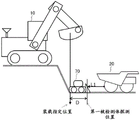
图1是矿山车辆运行系统的概略图。FIG. 1 is a schematic diagram of a mining vehicle operation system.
图2A是自卸车的侧视图。2A is a side view of the dump truck.
图2B是自卸车的平面图(俯视图)。FIG. 2B is a plan view (top view) of the dump truck.
图3A是自卸车的功能块图。3A is a functional block diagram of a dump truck.
图3B是倒车辅助装置的功能块图。3B is a functional block diagram of the reversing assist device.
图4A是装载机械的概略结构图。4A is a schematic configuration diagram of a loading machine.
图4B是装载位置指定装置的功能块图。FIG. 4B is a functional block diagram of the loading position specifying device.
图5是表示向装载位置停车前的概略的流程的流程图。FIG. 5 is a flowchart showing a schematic flow before parking at the loading position.
图6是表示倒车辅助处理的流程的流程图。FIG. 6 is a flowchart showing the flow of the reverse assist processing.
图7A是表示从装载停止位置到第一被检测体的判断距离D及第一距离L1的说明图(俯视)。7A is an explanatory diagram (plan view) showing the determination distance D and the first distance L1 from the loading stop position to the first object to be detected.
图7B是表示从装载停止位置到第一被检测体的判断距离D及第一距离L1的说明图(侧视)。7B is an explanatory diagram (side view) showing the determination distance D and the first distance L1 from the loading stop position to the first object to be detected.
图8是表示在步骤S602及S603执行的坐标转换处理的图。FIG. 8 is a diagram showing coordinate conversion processing executed in steps S602 and S603.
图9A是表示第一距离L1及第二距离L2的大小关系的例的图。FIG. 9A is a diagram showing an example of the magnitude relationship between the first distance L1 and the second distance L2.
图9B是表示第一距离L1及第二距离L2的大小关系的例的图。FIG. 9B is a diagram showing an example of the magnitude relationship between the first distance L1 and the second distance L2.
图10是表示步骤S604的判断结果为否定的情况的一例的图。FIG. 10 is a diagram showing an example of a case where the determination result in step S604 is negative.
图11是表示步骤S611中的目标停车位置距离的决定例的图。FIG. 11 is a diagram showing an example of determination of the target parking position distance in step S611 .
图12是搭载于有人自卸车的倒车辅助装置及外部装置的功能块图。FIG. 12 is a functional block diagram of a reverse assist device and an external device mounted on a manned dump truck.
图13是搭载于有人自卸车的倒车辅助装置及外部装置的功能块图。FIG. 13 is a functional block diagram of a reverse assist device and an external device mounted on a manned dump truck.
具体实施方式Detailed ways
以下,使用附图等,对本发明的实施方式进行说明。以下的说明表示本发明的内容的具体例,本发明不限定于这些说明,在本说明书公开的技术性思想的范围内,本领域技术人员可以进行各种变更及修正。另外,在用于说明本发明的全部图中,对于具有同一功能的部分,标注同一符号,有时省略其反复的说明。Hereinafter, embodiments of the present invention will be described with reference to the drawings and the like. The following description shows specific examples of the content of the present invention, and the present invention is not limited to these descriptions, and various changes and corrections can be made by those skilled in the art within the scope of the technical idea disclosed in this specification. In addition, in all the drawings for explaining the present invention, parts having the same functions are denoted by the same reference numerals, and repeated descriptions thereof may be omitted.
本实施方式涉及矿山车辆运行系统1,将本发明应用到了与管制服务器通信连接且根据从该管制服务器经由无线通信线路接收的管制指示信息进行自主行驶的自卸车。The present embodiment relates to a mining
图1是矿山车辆运行系统1的概略图。如图1所示,在矿山具有:通过挖掘机、轮式装载机等液压挖掘机10挖掘矿物、表土,并装载于自卸车20的装载场61;卸载装载于自卸车20的矿物、表土的放土场62;以及停放在矿山内使用的车辆、机械的停车场,而且,装载场61、放土场62以及停车场通过搬送路60连结。FIG. 1 is a schematic diagram of a mining
设置在上述矿山内的矿山车辆运行系统1构成为,将至少1台以上的自卸车20分别经由无线通信线路40通信连接于在管制局30所设置的管制服务器31。各自卸车接收从管制服务器31发送的管制指示信息,并据此自主行驶。The mining
在搬送路60、装载场61中,还行驶平地机、推土机、洒水车、轻型车等辅助作业车辆70。
图2A是自卸车的侧视图,图2B是自卸车的平面图(俯视图)。自卸车20具备右前轮21R、左前轮21L、右后轮22R、左后轮22L、车身框架23、搭载于车身框架23上的车斗24、以及设置于车身框架23的前部的驾驶室25。在自卸车20的右侧面具备监视自卸车20的右后方的右后方监视传感器30R,在自卸车20的左侧面具备监视自卸车20的左后方的左后方监视传感器30L(参照图2B)。2A is a side view of the dump truck, and FIG. 2B is a plan view (top view) of the dump truck. The
右后方监视传感器30R、及左后方监视传感器30L分别例如可以使用能够利用红外线的反射光取得至被检测体的距离的红外线距离传感器、能够使用两个图像通过利用立体视取得距离的立体相机等计算对称位置的被检测体距离的距离传感器。其中,右后方监视传感器30R将自卸车20的倒车方向作为扫描方向35,测量至第一被检测体的第一距离,并输出表示第一距离的第一距离信息,上述第一被检测体距离右后轮22R的接地面位于包含后轮的倒车时的轨迹的第一高度。而且,测量至第二被检测体的第二距离,并输出表示第二距离的第二距离信息,上述第二被检测体位于比第一高度高且包含车斗24的倒车时的轨迹的第二高度。同样地,左后方监视传感器30L测量至距离左后轮22L的接地面位于第一高度的第一被检测体的第一距离、及至距离左后轮22L的接地面位于第二高度的第二被检测体的第二距离,且输出第一距离信息及第二距离信息。The right
红外线距离传感器可以使用检测某一点的距离的固定型红外线距离传感器、通过使放射方向在红外线的某平面内移动而能够取得该平面上的多个点的距离的平面扫描型红外线距离传感器、可以使放射方向三维地动作来扫面空间的空间扫描型红外线距离传感器等。在使用固定型红外线距离传感器的情况下,右后方监视传感器30R及左后方监视传感器30L分别构成为包含安装于第一高度的固定型红外线距离传感器及安装于第二高度的固定型红外线距离传感器。The infrared distance sensor can use a fixed infrared distance sensor that detects the distance of a certain point, a plane scanning infrared distance sensor that can obtain the distance of a plurality of points on the plane by moving the radiation direction in a certain plane of infrared rays, and can use the infrared distance sensor. A space scanning infrared distance sensor, etc., which operates three-dimensionally in the radiation direction to scan the space. When a fixed infrared distance sensor is used, the right
作为一例,本实施方式中使用平面扫描型红外线距离传感器。平面扫描型红外线距离传感器的扫描范围是二维平面,设置为将自卸车20的从下方至后方的区包含于扫描范围。通过采用这样的传感器型号及传感器配置,由平面扫描型红外线距离传感器构成的右后方监视传感器30R及左后方监视传感器30L分别能够取得第一高度上的计量点的点列、及第二高度上的计量点的点列。也就是,右后方监视传感器30R兼备检测位于第一高度的第一被检测体的第一后方监视传感器和检测位于比第一高度高的第二高度的第二被检测体的第二后方监视传感器。同样,左后方监视传感器30L也兼备第一后方监视传感器、及第二后方监视传感器。As an example, a plane scanning infrared distance sensor is used in this embodiment. The scanning range of the plane-scanning infrared distance sensor is a two-dimensional plane, and is set so that the area from the bottom to the rear of the
作为其它例,也可以在后轮的车轴的左右方向中央部、及车斗的后端的左右方向中央部分别将平面扫描型红外线距离传感器以其计量面与行驶面大致平行的方式设置。As another example, a plane scanning infrared distance sensor may be provided in the left-right central portion of the axle of the rear wheel and the left-right central portion of the rear end of the body so that its measurement surface is substantially parallel to the running surface.
此外,在图2A中,将用于表示第一高度的检测位置的箭头的始点设为右后轮22R、左后轮22L的后端,将表示第二高度的检测位置的箭头的始点设为车斗24后端,并非限定将后方监视传感器配置于该位置。只要能够检测第一被检测体及第二被检测体,后方监视传感器不管配置于什么地方都可以。In addition, in FIG. 2A , the starting point of the arrow indicating the detection position of the first height is the rear end of the right
另外,理想的是将第一平面内及第二平面内的整个区域设为扫描范围,但是无需一定探测第一平面内整个域、及第二平面内整个区域,例如,如图2B所示,也可以灵活使用左右各自的角附近的距离。这样,就后方监视传感器的个数而言,可以在图2B所示的四个角的四点分别具备一个,合计四个传感器,可以在自卸车高度不同的两个点各具备一个传感器,进一步地,也可以具备一个将自卸车的高度方向包含于扫描面的传感器。In addition, it is desirable to set the entire area in the first plane and the entire area in the second plane as the scanning range, but it is not necessary to detect the entire area in the first plane and the entire area in the second plane. For example, as shown in FIG. 2B, The distances around the corners of the left and right can also be used flexibly. In this way, in terms of the number of rear monitoring sensors, one can be provided at each of the four points at the four corners shown in FIG. 2B , a total of four sensors can be provided, one sensor can be provided at each of the two points at different heights of the dump truck, and further Alternatively, a sensor that includes the height direction of the dump truck in the scanning surface may be provided.
图3A是自卸车的功能块图。自卸车20具备倒车辅助装置100。倒车辅助装置100是由包含CPU101、RAM102、ROM103、HDD104、输入输出接口(I/F105),且它们经由总线106相互连接而成的计算机构成的行驶辅助控制器。在I/F105的输入端分别连接无线通信装置28、右后方监视传感器30R、左后方监视传感器30L、以及本车位置传感器110,在输出端连接自主行驶控制装置120(由计算机构成的行驶控制控制器)。3A is a functional block diagram of a dump truck. The
倒车辅助装置100经由无线通信装置28从管制服务器31接收管制指示信息,从液压挖掘机10接收装载指定位置信息。The reversing
倒车辅助装置100从右后方监视传感器30R及左后方监视传感器30L分别接收传感器输出(包含作为至第一被检测体的距离的第一距离L1、作为至第二被检测体的距离的第二距离L2),从本车位置传感器110(GPS)接收本车位置信息。The reversing
另一方面,倒车辅助装置100向作为外部装置的自主行驶控制装置120输出倒车辅助装置100决定的目标停车位置信息和从管制服务器31接收到的管制指示信息。而且,也可以输出倒车辅助装置100决定的目标停车距离信息。On the other hand, the reversing
图3B是倒车辅助装置的功能块图。如图3B所示,倒车辅助装置100具备第一被检测体位置运算部111、第二被检测体位置运算部112、判断距离运算部113、允许接近体判断部114、目标停车距离运算部115、目标停车位置决定部116、输入控制部117、以及输出控制部118。上述各部可以通过构成倒车辅助装置100的硬件和实现各部的功能的软件的组合构成,也可以通过电路构成。各部的功能后面叙述。3B is a functional block diagram of the reversing assist device. As shown in FIG. 3B , the reversing
自主行驶控制装置120包含输入控制部121、及自主行驶控制部122。这些各部可以通过构成自主行驶控制装置120的硬件和实现各部的功能的软件的组合构成,也可以通过电路构成。自主行驶控制装置120连接于行驶马达211、转向马达212、以及制动装置213。自主行驶控制装置120按照管制指示信息及目的停车位置信息(也可以包含目的停车距离信息)将用于使自卸车20自主行驶的各种信号适当地输出至行驶马达211、转向马达212、以及制动装置213。The autonomous
图4A是装载机械的概略结构图。如图4A所示,液压挖掘机10具备:具备履带的下部行驶体11;可回旋地支撑于下部行驶体11上的上部回旋体12;搭载于上部回旋体12的驾驶座13;连结于上部回旋体12的前部的前作业机;计算液压挖掘机10的绝对坐标系的位置信息的位置计算装置(GPS)17;以及装载位置指定装置18。前作业机包含可俯仰动作地支撑的起重臂14、可旋转地支撑于起重臂14的前端的悬臂15、以及可旋转地支撑于悬臂15的前端的铲斗16。液压挖掘机10的操作人员使铲斗16位于向自卸车20的装载位置,当指定该位置时,装载位置指定装置18运算此时的铲斗16的绝对坐标系的坐标。4A is a schematic configuration diagram of a loading machine. As shown in FIG. 4A , the
图4B是装载位置指定装置的功能块图。液压挖掘机10具备检测起重臂14的俯仰角度的起重臂角度传感器141、检测悬臂15的旋转角度的悬臂角度传感器151、检测铲斗16的旋转角度的铲斗角度传感器161。装载位置指定装置18包含:基于来自起重臂角度传感器141、悬臂角度传感器151、以及铲斗角度传感器161的输出运算铲斗16相对于液压挖掘机10的相对位置的铲斗相对位置运算部181;对从GPS17取得的液压挖掘机10的绝对坐标系的位置信息加上铲斗相对位置运算部181运算出的铲斗16的相对位置,运算铲斗16的绝对位置的铲斗绝对位置运算部182;以及向自卸车20发送作为铲斗的绝对位置的装载指定位置信息的通信部183。FIG. 4B is a functional block diagram of the loading position specifying device. The
装载位置的指定操作可以构成为,在设置于液压挖掘机10的驾驶座的显示器显示装载机械周边的环境信息,在该显示器上,操作人员能够指定停车位置。当进行该装载位置的指定操作时,装载位置指定装置18取得此时的来自起重臂角度传感器141、悬臂角度传感器151、以及铲斗角度传感器161、GPS17的输出,运算铲斗绝对位置,并将其作为装载指定位置而输出。The designation operation of the loading position may be configured such that environmental information around the loading machine is displayed on a display provided on the driver's seat of the
以下说明例子:在液压挖掘机10被配置于比自卸车20的接地面高的位置,且挖掘工作面,向位于崖下的自卸车20装载货物的所谓上下台阶法时使用本实施方式的倒车辅助装置。An example will be described below. The reverse vehicle according to the present embodiment is used when the
如图2A所示,自卸车20在从侧方观察车身时的右后轮22R的后端(轮胎高度中央的水平方向后端)和车斗24的后端上下两个高度位置突出,该位置的与被检测体的接触的危险性高。因此,倒车时,要求避免在该两个平面的接触。As shown in FIG. 2A , when the vehicle body is viewed from the side, the rear end of the right
在此,液压挖掘机10在挖掘工作面本身的作业的性质上,假设存在于工作面附近。液压挖掘机10的铲斗16达不到那么远,因此,若考虑作业效率,则大多情况下,液压挖掘机10的操作人员指定的装载指定位置被指定在工作面附近。因此,在接近装载指定位置的位置探测到的被检测体能够认为是工作面。Here, it is assumed that the
工作面假设为从右后轮22R的接地面连续地立起。另外,工作面的形状随着挖掘作业的进展随时变形,但工作面的面为通过挖掘作业形成的人工的形状,不会从自卸车20的前轮21及后轮22的接地面突出得很大,是挖掘出的面形状。该情况下,自卸车20倒车时,在自卸车20充分靠近工作面时,必须在第一高度检测到工作面。由于以上的情况,在作为后轮22的后端部的高度的第一高度探测到的第一被检测体的位置与液压挖掘机10的操作人员指定的装载指定位置充分靠近的情况下,将第一被检测体判断为工作面。另一方面,在第一高度探测到的第一被检测体的位置远离装载指定位置的情况下,该被检测体能够认为不是工作面。若不是工作面,则自卸车20无需接近,由于假设为推土机等辅助作业车辆70,所以认为应在保持安全的距离的位置停车。It is assumed that the work surface continuously rises from the ground contact surface of the right
在此,自卸车20判断第一被检测体是否为工作面,若判断为是工作面,则比较从第一后方监视传感器到第一被检测体的距离(第一距离L1)和从第二后方监视传感器到第二被检测体的距离(第二距离L2),将较小的距离设为目标停车距离。另外,在判断为不是工作面的情况下,比较第一距离L1和第二距离L2,使用较小的距离、本车位置、以及用于安全的距离(称为“安全距离Ds”),计算目标停车距离,基于目标停车距离和本车位置决定目标停车位置。Here, the
以下,对自卸车20向液压挖掘机10的操作人员指定的装载位置一边使用倒车辅助装置一边自主行驶地接近并停在目标停车位置的处理进行说明。图5是表示向装载位置停车前的概略的流程的流程图。Hereinafter, the process of approaching the
自卸车20在放土场62卸载货物,然后在搬送路60行驶,朝向装载场61。在装载场61的入口,自卸车20对管制服务器31发送用于在装载场61的场内向液压挖掘机10行驶的路径数据的请求(S501)。The
管制服务器31相应请求而生成路径数据,并作为管制指示信息回复至自卸车20。自卸车20若取得路径数据(S502/是),则沿路径数据自主行驶(S503)。而且,自卸车20在取得路径数据前待机(S502/否)。The
若液压挖掘机10的操作人员进行装载位置的指定操作,则装载位置指定装置18将表示装载指定位置的绝对位置的装载指定位置信息发送至自卸车20及管制服务器31(S504)。When the operator of the
自卸车20生成包含折返地点且表示至装载指定位置信息所示的装载位置的路径的接近数据(S505),从管制服务器31发送至自卸车20,自卸车20取得(S506/是)。自卸车20取得接近数据前(S506/否),在折返地点待机。The
自卸车20一边接受倒车辅助装置100的行驶辅助,一边沿接近数据所示的路径倒车(S507)。在到达倒车辅助装置100决定的目标停车位置前,持续进行倒车辅助处理及倒车行驶(S508/否),若到达目标停车位置(S508/是),则停车,结束倒车辅助处理。The
接下来,对步骤S507的倒车辅助处理进行说明。图6是表示倒车辅助处理的流程的流程图。图7A是表示从装载停止位置到第一被检测体的判断距离D及第一距离L1的说明图(俯视)。图7B是表示从装载停止位置到第一被检测体的判断距离D及第一距离L1的说明图(侧视)。图8是表示在步骤S602及S603执行的坐标转换处理的图。图9A、图9B是表示第一距离L1及第二距离L2的大小关系的例的图。Next, the reversing assist processing in step S507 will be described. FIG. 6 is a flowchart showing the flow of the reverse assist processing. 7A is an explanatory diagram (plan view) showing the determination distance D and the first distance L1 from the loading stop position to the first object to be detected. 7B is an explanatory diagram (side view) showing the determination distance D and the first distance L1 from the loading stop position to the first object to be detected. FIG. 8 is a diagram showing coordinate conversion processing executed in steps S602 and S603. 9A and 9B are diagrams showing examples of the magnitude relationship between the first distance L1 and the second distance L2.
倒车辅助装置100的输入控制部117接受管制指示信息、本车位置信息、装载指定位置信息、右后方监视传感器30R、左后方监视传感器30L的传感器输出的输入。第一被检测体位置运算部111及第二被检测体位置运算部112分别从右后方监视传感器30R及左后方监视传感器30L取得传感器输出(包含第一距离L1、第二距离L2)(S601)。第一距离L1、第二距离L2基于来自右后方监视传感器30R及左后方监视传感器30L的输出各求出两个,可以从中选择任一方,例如较小的一方进行以下的处理,也可以使用从右后方监视传感器30R输出的第一距离L1、第二距离L2执行以下的处理,使用从左后方监视传感器30L输出的第一距离L1、第二距离L2执行以下的处理。The
第一被检测体位置运算部111使用第一距离L1和本车位置信息运算第一被检测体的绝对坐标的位置(S602)。The first subject
判断距离运算部113基于装载指定位置信息、从第一被检测体位置运算部111得到的第一被检测体位置信息,运算装载指定位置与第一被检测体位置之间的距离(以下,称为“判断距离D”)(S603)。The determination
参照图8,对第一被检测体位置运算部111及判断距离运算部113执行的坐标转换处理进行说明。图8中,用下标g表示矿山坐标系,用下标t表示自卸车坐标系,用下标s表示传感器坐标系。液压挖掘机10的操作人员指定的装载指定位置设为用矿山坐标系表示的坐标gPe。另外,自卸车的位置表示为用矿山坐标系表示的后轮轴中心的坐标gPt。Referring to FIG. 8 , the coordinate conversion processing executed by the first subject
在坐标转换处理中具有矿山坐标系、传感器坐标系、以及自卸车坐标系这三个。传感器坐标系通过使用右后方监视传感器及左后方监视传感器的安装于自卸车的安装位置与本车位置传感器计算的自卸车的车身中的本车位置计算基准位置的几何学的位置关系,进行向矿山坐标系的坐标转换。因此,判断距离运算部113及第一被检测体位置运算部111通过以下的数式1求出装载指定位置坐标及第一被检测体位置坐标,运算判断距离D。In the coordinate conversion processing, there are three coordinate systems, namely, a mine coordinate system, a sensor coordinate system, and a dump truck coordinate system. The sensor coordinate system is adjusted by using the geometrical positional relationship between the mounting position of the right rear monitoring sensor and the left rear monitoring sensor mounted on the dump truck and the host vehicle position calculation reference position in the body of the dump truck calculated by the host vehicle position sensor. Coordinate transformation of the mine coordinate system. Therefore, the determination
[数1][Number 1]
tP1=tPs sP1+tPs t P 1 = t P s s P 1 + t P s
gP1=gRt tP1+gPt=gRt(tRs sP1+tPs)+gPt g P 1 = g R t t P 1 + g P t = g R t ( t R s s P 1 + t P s ) + g P t
L1=|tP1-tPtire|L1=| t P 1 - t P tire |
D=|gPe-gP1|(向高度0的水平面投影)D=| g P e - g P 1 | (projection to the horizontal plane of height 0)
其中,in,
gRt表示从矿山坐标系观察的自卸车坐标系的姿势 g R t represents the posture of the dump truck coordinate system viewed from the mine coordinate system
tRs表示从自卸车坐标系观察的传感器坐标系的姿势 t R s represents the posture of the sensor coordinate system viewed from the tipper coordinate system
tP1表示从自卸车坐标系观察的第一被检测体的位置 t P 1 represents the position of the first subject viewed from the tipper coordinate system
sP1表示从传感器坐标系观察的第一被检测体的位置 s P 1 represents the position of the first subject viewed from the sensor coordinate system
tPs表示从自卸车坐标观察的传感器坐标系的位置 t P s represents the position of the sensor coordinate system viewed from the tipper coordinates
gP1表示从矿山坐标系观察的第一被检测体的位置 g P 1 represents the position of the first object viewed from the mine coordinate system
tPtire表示从自卸车坐标系观察的后轮轮胎后端的位置 t P tire represents the position of the rear end of the rear tire as viewed from the tipper coordinate system
gPe表示从矿山坐标系观察的装载指定位置 g P e represents the loading designation position viewed from the mine coordinate system
gPt表示从矿山坐标系观察的自卸车的位置 g P t represents the position of the dump truck viewed from the mine coordinate system
允许接近体判断部114判断判断距离D是否为预先设定的允许接近体判断阈值Dth以下(S604)。The approaching
若步骤S604的判断结果为肯定(S604/是),则判断为第一被检测体是允许接近体(S605),将该判断结果输出至目标停车距离运算部115。这里所谓的“允许接近体”是指即使自卸车20万一干涉也能够允许,在本例中,相当于工作面。若根据与非允许接近体的差异定义,则在后述的目标停车距离的运算中,无需确保安全距离Ds的被检测体可以称为允许接近体,需要确保安全距离Ds的被检测体可以称为非允许接近体。If the determination result of step S604 is affirmative (S604/YES), it is determined that the first detected object is an approaching object (S605), and the determination result is output to the target parking
目标停车距离运算部115比较第一距离L1及第二距离L2(S606),在第一距离L1为第二距离L2以下的情况下(S606/是,参照图9A),将第一距离L1决定为至目标停车位置的距离(S607),在第一距离L1比第二距离L2大的情况下(S606/否,参照图9B),将第二距离L2决定为至目标停车位置的距离(S608)。The target parking
若步骤S604的判断结果为否定(S604/否),则判断为第一被检测体是非允许接近体(例如,辅助作业车辆)(S609),并将该判断结果输出至目标停车距离运算部115。If the determination result in step S604 is negative (S604/NO), it is determined that the first detected object is a non-approachable object (for example, an auxiliary work vehicle) (S609), and the determination result is output to the target parking
目标停车距离运算部115比较第一距离L1及第二距离L2(S610),在第一距离L1为第二距离L2以下的场合(S610/是)下,使用预选设定的作为余裕的安全距离Ds,将从第一距离L1减去安全距离Ds得到的值决定为至目标停车位置的距离(S611),在第一距离L1比第二距离L2大的情况下(S610/否),将从第二距离L2减去安全距离Ds得到的值决定为至目标停车位置的距离(S612)。安全距离Ds例如可以使用10m以上的值。The target parking
图10是表示步骤S604的判断结果为否定的情况的一例的图。在工作面与自卸车20之间具有辅助作业车辆70。该情况下,右后方监视传感器30R及左后方监视传感器30L作为第一被检测体不是检测工作面,而是辅助作业车辆70。判断距离D是从装载停止位置到辅助作业车辆70的最靠近自卸车20的点(第一被检测体探测位置)的距离。通常,装载指定位置被指定为工作面附近,因此,(D-L1)的绝对值比Dth大。FIG. 10 is a diagram showing an example of a case where the determination result in step S604 is negative. An
图11是表示步骤S611中的目标停车位置距离的决定例的图。在工作面跟前具有辅助作业车辆70,因此,以不与其干涉的方式将比第一被检测体探测位置更靠作为余裕的安全距离Ds跟前作为目标停车位置。由此,目标停车距离运算部115将从第一距离L1减去安全距离Ds得到的距离计算为目标停车距离。图11举例说明了第一距离L1,但在第二距离L2比第一距离小的情况下,只要将第一距离L1换做第二距离L2即可。FIG. 11 is a diagram showing an example of determination of the target parking position distance in step S611 . Since there is an
然后,目标停车位置决定部116使用目标停车距离和本车位置决定目标停车位置(S613)。在从步骤S607、步骤S608转到本步骤的情况下,可以认为有效地在工作面附近停车,因此,目标停车位置被决定更为该(D-L1)、或(D-L2)成为零附近的地方。Then, the target parking
另一方面,在从步骤S611、步骤S612转到本步骤的情况下,此时,第一被检测体或第二被检测体可能是推土机等辅助作业车辆,因此,应当不接近,在保持安全距离Ds的位置停车,因此,以在对至被检测体的距离考虑到安全距离Ds的距离成为零附近的地方停车的方式决定停车位置。On the other hand, when the process proceeds from step S611 and step S612 to this step, at this time, the first subject or the second subject may be an auxiliary work vehicle such as a bulldozer, and therefore, should not approach, in order to maintain safety Since the vehicle is parked at a distance Ds, the parking position is determined so as to park at a position where the distance to the subject is considered to be near zero in consideration of the safety distance Ds.
根据本实施方式,在向液压挖掘机10的操作人员指定的装载停止位置倒车时,在本车辆与装载停止位置之间若具有非允许接近体,则将确保安全距离的位置设为目标停车位置,若不存在非允许接近体,则将装载停止位置设为目标停车位置,并向该位置倒车。在此,决定目标停车位置时,并非使用行驶面与非行驶面的部分、例如工作面的边界线,因此,无需更新边界线,即使边界线的位置、形状随时变化,也无需将其取得,能够期待作业效率的提高。According to the present embodiment, when reversing to the loading stop position designated by the operator of the
上述实施方式中举例说明了自主行驶车辆,但也可以将本发明应用于在自卸车20搭乘驾驶员,且根据其驾驶操作使自卸车行驶的所谓的有人自卸车的倒车辅助。图12、图13是搭载于有人自卸车的倒车辅助装置及外部装置的功能块图。In the above-described embodiment, the autonomous vehicle is described as an example, but the present invention can also be applied to a so-called manned dump truck reversing assistance in which the driver rides on the
如图12所示,连接倒车辅助装置100的输出端和设于自卸车20的驾驶室25内的信息提供装置250(由计算机构成的信息提供控制器)的输入端,在该信息提供装置250的输出端连接监视器261、警报器262的至少一个。信息提供装置250包含输入控制部251、显示控制部252、以及警告部253。显示控制部252也可以在监视器261显示表示决定了的目标停车位置的图像。在该画面同时显示本车辆的位置,从而能够更简单地掌握本车辆与目标停车位置的位置关系。而且,也可以将目标停车距离显示为数值。由此,能够对驾驶员通知至目标停车位置的倒车行驶距离,进行驾驶辅助。As shown in FIG. 12, the output end of the reversing
另外,例如,也可以构成为,在步骤S604的判断为否定的情况下,将表示该结果的信息输出至信息提供装置250,警告部253从警报器262输出警报。In addition, for example, when the determination in step S604 is negative, information indicating the result may be output to the
另外,作为从倒车辅助装置100输出目标停车位置的外部装置的例,如图13所示,也可以使用自卸车20的减速指令生成装置270。减速指令生成装置270包含输入控制部271、减速指令生成部272以及行驶控制部273,减速指令生成部272根据目标停车距离以在该距离成为零的位置停车的方式向行驶控制部273输出减速指令,行驶控制部273控制行驶马达281或制动装置282,从而调整速度,并且在目标停车位置停车。由此,即使在存在辅助作业车辆70的情况下,也能够避免与之干涉,并且朝向目标停车位置自动停止,能够抑制驾驶员的操作错误。In addition, as an example of an external device that outputs the target parking position from the reversing
根据本结构,在判断为工作面的情况和非工作面的情况下,能够恰当地确保减速指令输出的至后方的被检测体的距离,能够抑制产生不必要的操作介入。According to this configuration, when it is determined to be a working face or a non-working face, it is possible to appropriately secure the distance to the object behind which the deceleration command is output, and to suppress unnecessary intervention.
本发明不限定于上述实施方式,不变更本发明的宗旨的各种实施方式、实施例属于本发明。The present invention is not limited to the above-described embodiments, and various embodiments and examples that do not change the gist of the present invention belong to the present invention.
符号说明Symbol Description
1—矿山车辆运行系统,10—液压挖掘机,18—倒车辅助装置,20—自卸车,31—管制服务器,70—辅助作业车辆。1—Mining vehicle operation system, 10—Hydraulic excavator, 18—Reversing auxiliary device, 20—Dump truck, 31—Control server, 70—Auxiliary operation vehicle.
Claims (4)
Applications Claiming Priority (3)
| Application Number | Priority Date | Filing Date | Title |
|---|---|---|---|
| JP2017-035136 | 2017-02-27 | ||
| JP2017035136A JP6752168B2 (en) | 2017-02-27 | 2017-02-27 | Dump truck and retreat support device |
| PCT/JP2018/007267 WO2018155709A1 (en) | 2017-02-27 | 2018-02-27 | Dump truck and reversing assistance device |
Publications (2)
| Publication Number | Publication Date |
|---|---|
| CN109844834A CN109844834A (en) | 2019-06-04 |
| CN109844834B true CN109844834B (en) | 2021-07-09 |
Family
ID=63252885
Family Applications (1)
| Application Number | Title | Priority Date | Filing Date |
|---|---|---|---|
| CN201880003827.4A Active CN109844834B (en) | 2017-02-27 | 2018-02-27 | Dump truck and reversing aids |
Country Status (4)
| Country | Link |
|---|---|
| US (1) | US11292469B2 (en) |
| JP (1) | JP6752168B2 (en) |
| CN (1) | CN109844834B (en) |
| WO (1) | WO2018155709A1 (en) |
Families Citing this family (17)
| Publication number | Priority date | Publication date | Assignee | Title |
|---|---|---|---|---|
| US10883256B2 (en) * | 2018-05-25 | 2021-01-05 | Deere & Company | Object responsive control system for a work machine |
| US11353881B2 (en) * | 2018-10-04 | 2022-06-07 | Modular Mining Systems, Inc. | Systems and methods for guided maneuvering with wave-off alerts |
| CN111399494B (en) * | 2019-01-02 | 2023-07-14 | 长沙智能驾驶研究院有限公司 | An unmanned loading guidance method, device and system |
| JP7172794B2 (en) * | 2019-03-27 | 2022-11-16 | トヨタ自動車株式会社 | Autonomous driving system |
| US11055864B2 (en) * | 2019-05-24 | 2021-07-06 | Nanjing Polagis Technology Co. Ltd | Method and apparatus for determining a geographic position of a target object on a street view map |
| US11226627B2 (en) | 2019-06-20 | 2022-01-18 | Caterpillar Global Mining Llc | System for modifying a spot location |
| JP7400425B2 (en) * | 2019-12-10 | 2023-12-19 | コベルコ建機株式会社 | Remote operation support system for working machines |
| BR112022011724A2 (en) * | 2019-12-18 | 2022-08-30 | Volvo Constr Equip Ab | A METHOD OF OPERATING A FLEET OF AUTONOMOUS VEHICLES |
| CN111474929B (en) * | 2020-04-10 | 2023-11-03 | 三一智矿科技有限公司 | Mine charging method and device |
| JP7354975B2 (en) * | 2020-09-25 | 2023-10-03 | コベルコ建機株式会社 | Stop instruction system |
| JP7137605B2 (en) | 2020-11-06 | 2022-09-14 | 日立建機株式会社 | Vehicle management system |
| EP4250047A4 (en) | 2020-11-17 | 2024-09-04 | Hitachi Construction Machinery Co., Ltd. | DUMP TRUCK CONTROL SYSTEM |
| CN112651132B (en) * | 2020-12-29 | 2022-02-11 | 清华大学苏州汽车研究院(相城) | Expected function safety risk assessment method for misoperation of automatic driving vehicle |
| CA3230190A1 (en) * | 2021-08-25 | 2023-03-02 | Technological Resources Pty Limited | Methods and systems for mining |
| WO2024082073A1 (en) * | 2022-10-17 | 2024-04-25 | Sepulveda Leon Gagarin Anibal | System, mining vehicle and method for detecting and monitoring parapets in a mining environment |
| KR102524105B1 (en) * | 2022-11-30 | 2023-04-21 | (주)토탈소프트뱅크 | Apparatus for recognizing occupied space by objects |
| CN116968743B (en) * | 2023-08-30 | 2024-03-19 | 梁山华鲁专用汽车制造有限公司 | Dump truck and reversing auxiliary device |
Citations (14)
| Publication number | Priority date | Publication date | Assignee | Title |
|---|---|---|---|---|
| CN1591255A (en) * | 2003-08-28 | 2005-03-09 | 丰田自动车株式会社 | Vehicle backward movement assist device and vehicle parking assist device |
| CN103443837A (en) * | 2011-03-31 | 2013-12-11 | 日立建机株式会社 | Position adjustment assistance system for transportation machine |
| CN103661179A (en) * | 2012-09-13 | 2014-03-26 | 祖新华 | Intelligent automobile safety system |
| KR20140002712U (en) * | 2012-10-30 | 2014-05-09 | 현대중공업 주식회사 | Safety device of vessel block transformer |
| CN103826918A (en) * | 2012-09-21 | 2014-05-28 | 株式会社小松制作所 | Periphery-monitoring system for work vehicle and work vehicle |
| CN103826920A (en) * | 2011-09-29 | 2014-05-28 | 日立建机株式会社 | Body structure for dump truck |
| CN104509103A (en) * | 2012-08-03 | 2015-04-08 | 日立建机株式会社 | Conveyance vehicle surveillance device |
| JP2015081877A (en) * | 2013-10-24 | 2015-04-27 | 日立建機株式会社 | Reverse travelling support system |
| CN104769630A (en) * | 2013-08-20 | 2015-07-08 | 株式会社小松制作所 | Management system and management method |
| CN105074382A (en) * | 2013-09-13 | 2015-11-18 | 日立建机株式会社 | dump truck |
| CN105313890A (en) * | 2014-05-29 | 2016-02-10 | 陕西重型汽车有限公司 | Automobile reversing auxiliary system |
| CN105467991A (en) * | 2014-09-29 | 2016-04-06 | 日立建机株式会社 | Stop position determining device for transport vehicle and transport vehicle with the same |
| CN105531996A (en) * | 2014-02-18 | 2016-04-27 | 日立建机株式会社 | Obstacle detection device for working machinery |
| CN106462166A (en) * | 2016-04-28 | 2017-02-22 | 株式会社小松制作所 | Management device for construction machinery |
Family Cites Families (3)
| Publication number | Priority date | Publication date | Assignee | Title |
|---|---|---|---|---|
| JP4605807B2 (en) | 1998-02-13 | 2011-01-05 | 株式会社小松製作所 | Vehicle guidance device |
| US9823082B2 (en) * | 2011-08-24 | 2017-11-21 | Modular Mining Systems, Inc. | Driver guidance for guided maneuvering |
| JP5933004B2 (en) * | 2014-04-25 | 2016-06-08 | 株式会社小松製作所 | Perimeter monitoring system, work vehicle, and perimeter monitoring method |
-
2017
- 2017-02-27 JP JP2017035136A patent/JP6752168B2/en active Active
-
2018
- 2018-02-27 US US16/477,565 patent/US11292469B2/en active Active
- 2018-02-27 CN CN201880003827.4A patent/CN109844834B/en active Active
- 2018-02-27 WO PCT/JP2018/007267 patent/WO2018155709A1/en not_active Ceased
Patent Citations (14)
| Publication number | Priority date | Publication date | Assignee | Title |
|---|---|---|---|---|
| CN1591255A (en) * | 2003-08-28 | 2005-03-09 | 丰田自动车株式会社 | Vehicle backward movement assist device and vehicle parking assist device |
| CN103443837A (en) * | 2011-03-31 | 2013-12-11 | 日立建机株式会社 | Position adjustment assistance system for transportation machine |
| CN103826920A (en) * | 2011-09-29 | 2014-05-28 | 日立建机株式会社 | Body structure for dump truck |
| CN104509103A (en) * | 2012-08-03 | 2015-04-08 | 日立建机株式会社 | Conveyance vehicle surveillance device |
| CN103661179A (en) * | 2012-09-13 | 2014-03-26 | 祖新华 | Intelligent automobile safety system |
| CN103826918A (en) * | 2012-09-21 | 2014-05-28 | 株式会社小松制作所 | Periphery-monitoring system for work vehicle and work vehicle |
| KR20140002712U (en) * | 2012-10-30 | 2014-05-09 | 현대중공업 주식회사 | Safety device of vessel block transformer |
| CN104769630A (en) * | 2013-08-20 | 2015-07-08 | 株式会社小松制作所 | Management system and management method |
| CN105074382A (en) * | 2013-09-13 | 2015-11-18 | 日立建机株式会社 | dump truck |
| JP2015081877A (en) * | 2013-10-24 | 2015-04-27 | 日立建機株式会社 | Reverse travelling support system |
| CN105531996A (en) * | 2014-02-18 | 2016-04-27 | 日立建机株式会社 | Obstacle detection device for working machinery |
| CN105313890A (en) * | 2014-05-29 | 2016-02-10 | 陕西重型汽车有限公司 | Automobile reversing auxiliary system |
| CN105467991A (en) * | 2014-09-29 | 2016-04-06 | 日立建机株式会社 | Stop position determining device for transport vehicle and transport vehicle with the same |
| CN106462166A (en) * | 2016-04-28 | 2017-02-22 | 株式会社小松制作所 | Management device for construction machinery |
Also Published As
| Publication number | Publication date |
|---|---|
| CN109844834A (en) | 2019-06-04 |
| US20190367030A1 (en) | 2019-12-05 |
| US11292469B2 (en) | 2022-04-05 |
| JP2018142113A (en) | 2018-09-13 |
| WO2018155709A1 (en) | 2018-08-30 |
| JP6752168B2 (en) | 2020-09-09 |
Similar Documents
| Publication | Publication Date | Title |
|---|---|---|
| CN109844834B (en) | Dump truck and reversing aids | |
| US9052716B2 (en) | System for indicating parking position and direction of dump truck and hauling system | |
| CN112384661B (en) | Transport vehicle, system comprising a work machine for loading a transport vehicle with a raw material, method and work machine | |
| US10119244B2 (en) | System and method for controlling a work machine | |
| CN107407074B (en) | Display system and construction machinery | |
| JP7274831B2 (en) | working machine | |
| EP4427108B1 (en) | System and method for controlling travel of work machine | |
| JP7236826B2 (en) | working machine | |
| JP6529595B2 (en) | Control system for transport vehicle, transport vehicle, and control method for transport vehicle | |
| US12012729B2 (en) | System and method for automatically controlling work machine including work implement | |
| US11454006B2 (en) | Control system for work vehicle, method and work vehicle | |
| JP2017016477A (en) | Work machine travel assist system and transport vehicle | |
| US20220081879A1 (en) | System, method and device for calibrating work machine | |
| JP7245581B2 (en) | Systems and methods for controlling work machines that load materials onto haul vehicles | |
| JPWO2019187192A1 (en) | Work machine control systems, methods, and work machines | |
| US20230359209A1 (en) | Stability system for an articulated machine | |
| US11136742B2 (en) | System for controlling work vehicle, method for controlling work vehicle, and work vehicle | |
| US20250052892A1 (en) | Vehicle determination system | |
| US20240295096A1 (en) | System and method for controlling work machine | |
| US12359397B2 (en) | System for controlling work machine, method, and work machine | |
| US12006656B2 (en) | Work vehicle, control device for work vehicle, and method for specifying direction of work vehicle | |
| JP6761845B2 (en) | Dump truck control system and dump truck | |
| JP2025034797A (en) | Control system for loading machine, control method for loading machine, and remote operation system for loading machine | |
| WO2024062899A1 (en) | System including work machine and method for controlling work machine | |
| WO2024004984A1 (en) | Work machine |
Legal Events
| Date | Code | Title | Description |
|---|---|---|---|
| PB01 | Publication | ||
| PB01 | Publication | ||
| SE01 | Entry into force of request for substantive examination | ||
| SE01 | Entry into force of request for substantive examination | ||
| GR01 | Patent grant | ||
| GR01 | Patent grant |