CN109792580B - Ultrasonic transducer and method for manufacturing the same - Google Patents
Ultrasonic transducer and method for manufacturing the same Download PDFInfo
- Publication number
- CN109792580B CN109792580B CN201680089736.8A CN201680089736A CN109792580B CN 109792580 B CN109792580 B CN 109792580B CN 201680089736 A CN201680089736 A CN 201680089736A CN 109792580 B CN109792580 B CN 109792580B
- Authority
- CN
- China
- Prior art keywords
- vibration
- end side
- side block
- node
- longitudinal axis
- Prior art date
- Legal status (The legal status is an assumption and is not a legal conclusion. Google has not performed a legal analysis and makes no representation as to the accuracy of the status listed.)
- Active
Links
Images


Classifications
-
- A—HUMAN NECESSITIES
- A61—MEDICAL OR VETERINARY SCIENCE; HYGIENE
- A61B—DIAGNOSIS; SURGERY; IDENTIFICATION
- A61B17/00—Surgical instruments, devices or methods
- A61B17/32—Surgical cutting instruments
- A61B17/320068—Surgical cutting instruments using mechanical vibrations, e.g. ultrasonic
- A61B17/320092—Surgical cutting instruments using mechanical vibrations, e.g. ultrasonic with additional movable means for clamping or cutting tissue, e.g. with a pivoting jaw
-
- A—HUMAN NECESSITIES
- A61—MEDICAL OR VETERINARY SCIENCE; HYGIENE
- A61B—DIAGNOSIS; SURGERY; IDENTIFICATION
- A61B17/00—Surgical instruments, devices or methods
- A61B17/32—Surgical cutting instruments
- A61B17/320068—Surgical cutting instruments using mechanical vibrations, e.g. ultrasonic
-
- H—ELECTRICITY
- H04—ELECTRIC COMMUNICATION TECHNIQUE
- H04R—LOUDSPEAKERS, MICROPHONES, GRAMOPHONE PICK-UPS OR LIKE ACOUSTIC ELECTROMECHANICAL TRANSDUCERS; DEAF-AID SETS; PUBLIC ADDRESS SYSTEMS
- H04R17/00—Piezoelectric transducers; Electrostrictive transducers
-
- H—ELECTRICITY
- H04—ELECTRIC COMMUNICATION TECHNIQUE
- H04R—LOUDSPEAKERS, MICROPHONES, GRAMOPHONE PICK-UPS OR LIKE ACOUSTIC ELECTROMECHANICAL TRANSDUCERS; DEAF-AID SETS; PUBLIC ADDRESS SYSTEMS
- H04R17/00—Piezoelectric transducers; Electrostrictive transducers
- H04R17/10—Resonant transducers, i.e. adapted to produce maximum output at a predetermined frequency
-
- H—ELECTRICITY
- H04—ELECTRIC COMMUNICATION TECHNIQUE
- H04R—LOUDSPEAKERS, MICROPHONES, GRAMOPHONE PICK-UPS OR LIKE ACOUSTIC ELECTROMECHANICAL TRANSDUCERS; DEAF-AID SETS; PUBLIC ADDRESS SYSTEMS
- H04R3/00—Circuits for transducers, loudspeakers or microphones
-
- H—ELECTRICITY
- H04—ELECTRIC COMMUNICATION TECHNIQUE
- H04R—LOUDSPEAKERS, MICROPHONES, GRAMOPHONE PICK-UPS OR LIKE ACOUSTIC ELECTROMECHANICAL TRANSDUCERS; DEAF-AID SETS; PUBLIC ADDRESS SYSTEMS
- H04R31/00—Apparatus or processes specially adapted for the manufacture of transducers or diaphragms therefor
-
- A—HUMAN NECESSITIES
- A61—MEDICAL OR VETERINARY SCIENCE; HYGIENE
- A61B—DIAGNOSIS; SURGERY; IDENTIFICATION
- A61B17/00—Surgical instruments, devices or methods
- A61B17/32—Surgical cutting instruments
- A61B17/320068—Surgical cutting instruments using mechanical vibrations, e.g. ultrasonic
- A61B2017/320089—Surgical cutting instruments using mechanical vibrations, e.g. ultrasonic node location
Landscapes
- Health & Medical Sciences (AREA)
- Engineering & Computer Science (AREA)
- Surgery (AREA)
- Life Sciences & Earth Sciences (AREA)
- Physics & Mathematics (AREA)
- Acoustics & Sound (AREA)
- Signal Processing (AREA)
- Medical Informatics (AREA)
- Veterinary Medicine (AREA)
- Nuclear Medicine, Radiotherapy & Molecular Imaging (AREA)
- Molecular Biology (AREA)
- Animal Behavior & Ethology (AREA)
- General Health & Medical Sciences (AREA)
- Public Health (AREA)
- Heart & Thoracic Surgery (AREA)
- Dentistry (AREA)
- Biomedical Technology (AREA)
- Mechanical Engineering (AREA)
- Manufacturing & Machinery (AREA)
- Surgical Instruments (AREA)
- Transducers For Ultrasonic Waves (AREA)
Abstract
超声波转换器具备以在沿着长度轴线的方向上被夹在顶端侧块和基端侧块之间的状态安装在螺栓的外周的驱动单元,所述驱动单元具备通过供给电能而产生超声波振动的压电元件。所述超声波转换器通过传递在压电元件产生的超声波振动,从而以在所述驱动单元产生的第1振动波节和在所述螺栓产生的第2振动波节在沿着所述长度轴线的方向上的相互偏移被抑制的状态进行振动。
The ultrasonic transducer includes a drive unit mounted on the outer periphery of a bolt, sandwiched between a top end block and a base end block along a length axis. The drive unit includes a piezoelectric element that generates ultrasonic vibrations by supplying electrical energy. The ultrasonic transducer vibrates by transmitting the ultrasonic vibrations generated in the piezoelectric element, thereby suppressing the mutual offset between the first vibration node generated by the drive unit and the second vibration node generated by the bolt along the length axis.
Description
技术领域technical field
本发明涉及具备通过供给电能而产生超声波振动的压电元件的超声波转换器及该超声波转换器的制造方法。The present invention relates to an ultrasonic transducer including a piezoelectric element that generates ultrasonic vibrations by supplying electrical energy, and a method of manufacturing the ultrasonic transducer.
背景技术Background technique
在US2009/275864A1中公开了使用超声波振动来处置处置对象的超声波处置器具。在该超声波处置器具设有超声波转换器,该超声波转换器具备通过供给电能而产生超声波振动的压电元件。在该超声波转换器中,螺栓的顶端部连接于顶端侧块,螺栓和顶端侧块一体地形成。此外,在螺栓的外周安装有包含压电元件的驱动单元。螺栓的基端部连接于基端侧块,在螺栓的外周连结有基端侧块。驱动单元被夹在顶端侧块和基端侧块之间,从基端侧块对驱动单元向顶端侧作用按压力。US2009/275864A1 discloses an ultrasonic treatment instrument that uses ultrasonic vibration to treat a treatment object. The ultrasonic treatment instrument is provided with an ultrasonic transducer including a piezoelectric element that generates ultrasonic vibrations by supplying electric energy. In this ultrasonic transducer, the distal end portion of the bolt is connected to the distal end block, and the bolt and the distal end block are integrally formed. In addition, a drive unit including a piezoelectric element is attached to the outer periphery of the bolt. The base end portion of the bolt is connected to the base end side block, and the base end side block is connected to the outer periphery of the bolt. The drive unit is sandwiched between the distal end side block and the proximal end side block, and a pressing force acts on the drive unit toward the distal end side from the proximal end side block.
在US2009/275864A1这样的超声波转换器中,螺栓和压电元件的剪切模量等材质互不相同。此外,构成超声波转换器的每个构件的形状等都不相同。因此,在根据由压电元件产生的超声波振动而超声波转换器振动的状态下,存在由构成超声波转换器的每个构件的材质和形状等的差异引起在驱动单元产生的振动波节和在螺栓产生的振动波节在沿着长度轴线的方向上相互偏移的可能性。若在驱动单元的振动波节与螺栓的振动波节之间产生偏移,则存在向压电元件输出的输出电流与输出电压之间的相位差变大、产生与期望的振动不同的非正常振动的可能性。因而,由于在驱动单元的振动波节与螺栓的振动波节之间产生偏移,从而在电能向振动能量的转换过程中损失增加,由能量的损失引起的超声波转换器处的发热也增加。In the ultrasonic transducer such as US2009/275864A1, the materials such as the shear modulus of the bolt and the piezoelectric element are different from each other. In addition, the shape and the like of each member constituting the ultrasonic transducer are different. Therefore, in a state where the ultrasonic transducer vibrates according to the ultrasonic vibration generated by the piezoelectric element, there are vibration nodes generated in the drive unit and bolts caused by differences in the material and shape of each member constituting the ultrasonic transducer. The likelihood that the resulting vibrational nodes will be offset from each other along the length axis. If there is a shift between the vibration node of the drive unit and the vibration node of the bolt, the phase difference between the output current and the output voltage output to the piezoelectric element increases, resulting in abnormal vibration different from the expected vibration. Possibility of vibration. Thus, since a shift occurs between the vibration nodes of the drive unit and the vibration nodes of the bolt, losses increase during the conversion of electrical energy to vibration energy, and heat generation at the ultrasonic transducer due to the loss of energy also increases.
发明内容SUMMARY OF THE INVENTION
本发明即是为了解决所述问题而完成的,其目的在于,提供在电能向振动能量的转换过程中减少损失的超声波转换器及该超声波转换器的制造方法。The present invention has been made to solve the above-mentioned problems, and an object of the present invention is to provide an ultrasonic transducer and a method for manufacturing the ultrasonic transducer that reduce loss in the process of converting electrical energy into vibration energy.
为了达到所述目的,本发明的一个技术方案的超声波转换器包括:螺栓,其具有基端和顶端,该螺栓从基端沿着长度轴线延伸设置到顶端;顶端侧块,其连接于所述螺栓的顶端部;基端侧块,其连接于所述螺栓的基端部;以及驱动单元,其具备通过供给电能而产生超声波振动的压电元件,并且以在沿着所述长度轴线的方向上被夹在所述顶端侧块和所述基端侧块之间的状态安装在所述螺栓的外周,该驱动单元通过传递在所述压电元件产生的所述超声波振动,从而以在所述驱动单元产生的第1振动波节和在所述螺栓产生的第2振动波节在沿着所述长度轴线的所述方向上的相互偏移被抑制的状态与所述螺栓、所述顶端侧块及所述基端侧块一起进行振动。In order to achieve the object, an ultrasonic transducer according to one technical solution of the present invention includes: a bolt having a base end and a top end, the bolt extending from the base end to the top end along a longitudinal axis; a top end side block connected to the top end a top end portion of a bolt; a base end side block connected to the base end portion of the bolt; and a drive unit provided with a piezoelectric element that generates ultrasonic vibrations by supplying electric energy, and is arranged in a direction along the longitudinal axis The drive unit is mounted on the outer periphery of the bolt in a state of being sandwiched between the distal end side block and the proximal end side block, and the drive unit transmits the ultrasonic vibration generated in the piezoelectric element to The state in which the mutual offset of the first vibration node generated by the drive unit and the second vibration node generated by the bolt in the direction along the longitudinal axis is suppressed is the same as that of the bolt and the tip. The side block and the base end side block vibrate together.
本发明的一个技术方案的超声波转换器的制造方法包括以下的过程:在从基端沿着长度轴线延伸设置到顶端的螺栓的外周安装具备压电元件的驱动单元;在沿着所述长度轴线的方向上在连接于所述螺栓的顶端部的顶端侧块和连接于所述螺栓的基端部的基端侧块之间夹持所述驱动单元;通过向所述压电元件供给电能而在所述压电元件产生超声波振动,根据产生的所述超声波振动而使所述螺栓、所述顶端侧块、所述基端侧块及所述驱动单元一起进行振动;在所述螺栓、所述顶端侧块、所述基端侧块及所述驱动单元一起进行振动的状态下,对在所述驱动单元产生的第1振动波节和在所述螺栓产生的第2振动波节在沿着所述长度轴线的所述方向上的相对位置进行检测;以及基于所述第1振动波节和所述第2振动波节的所述相对位置的检测结果,对产生所述第1振动波节的外侧振动系统中的振动状态和产生所述第2振动波节的内侧振动系统中的振动状态进行调整,成为所述第1振动波节和所述第2振动波节在沿着所述长度轴线的所述方向上的相互偏移被抑制的状态。A method of manufacturing an ultrasonic transducer according to an aspect of the present invention includes the following steps: attaching a drive unit including a piezoelectric element to the outer periphery of a bolt extending from the base end to the tip along the longitudinal axis; The drive unit is sandwiched between a top end side block connected to the top end portion of the bolt and a base end side block connected to the base end portion of the bolt in the direction of the bolt; Ultrasonic vibration is generated in the piezoelectric element, and the bolt, the distal end side block, the proximal end side block, and the drive unit are vibrated together according to the generated ultrasonic vibration; In a state where the top end side block, the base end side block and the drive unit vibrate together, the first vibration node generated by the drive unit and the second vibration node generated by the bolt are aligned. detecting the relative position in the direction of the longitudinal axis; and generating the first vibration wave based on the detection result of the relative position of the first vibration node and the second vibration node The vibration state in the outer vibration system of the node and the vibration state in the inner vibration system generating the second vibration node are adjusted so that the first vibration node and the second vibration node are along the A state in which mutual offset in the direction of the longitudinal axis is suppressed.
附图说明Description of drawings
图1是表示使用第1实施方式的超声波转换器的处置系统的概略图。FIG. 1 is a schematic diagram showing a treatment system using the ultrasonic transducer according to the first embodiment.
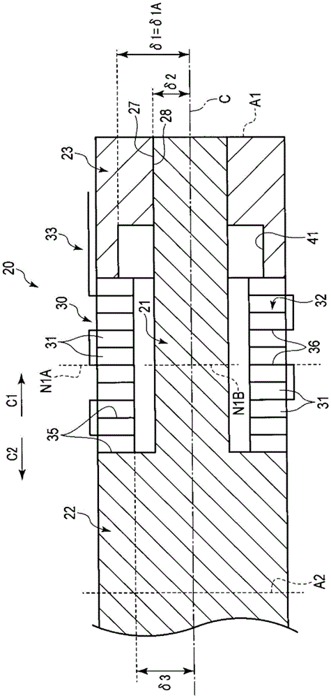
图2是概略地表示第1实施方式的超声波转换器的结构的剖视图。2 is a cross-sectional view schematically showing the configuration of the ultrasonic transducer according to the first embodiment.
图3A是表示第1振动波节和第2振动波节并未相互偏移的状态下的、向驱动单元输出的输出电流与输出电压之间的相位差及输出的频率从PLL控制开始时的经时变化的一个例子的概略图。3A shows the phase difference between the output current and the output voltage output to the drive unit and the output frequency when the PLL control is started in a state where the first vibration node and the second vibration node are not shifted from each other A schematic diagram of an example of changes over time.
图3B是表示第2振动波节位于比第1振动波节靠顶端侧的位置的状态下的、向驱动单元输出的输出电流与输出电压之间的相位差及输出的频率从PLL控制开始时的经时变化的一个例子概略图。3B shows the phase difference between the output current and the output voltage output to the drive unit and the frequency of the output when the PLL control is started in a state where the second vibration node is located on the distal side of the first vibration node An example schematic diagram of changes over time.
图4是表示在第1实施方式中通过调整从长度轴线到非接触部在径向上的距离而抑制第1振动波节和第2振动波节的相互偏移的方法的一个例子的概略图。4 is a schematic diagram showing an example of a method of suppressing mutual displacement of the first vibration node and the second vibration node by adjusting the distance from the longitudinal axis to the non-contact portion in the radial direction in the first embodiment.
图5是表示在第1变形例中通过调整非接触部在沿着长度轴线的方向上的尺寸而抑制第1振动波节和第2振动波节的相互偏移的方法的一个例子的概略图。5 is a schematic diagram showing an example of a method of suppressing the mutual displacement of the first vibration node and the second vibration node by adjusting the dimension of the non-contact portion in the direction along the longitudinal axis in the first modification .
图6是表示在第2变形例中通过调整第2延伸设置区域中的第2面积而抑制第1振动波节和第2振动波节的相互偏移的方法的一个例子以及在第3变形例中通过调整第2延伸设置区域在沿着长度轴线的方向上的尺寸而抑制第1振动波节和第2振动波节的相互偏移的方法的一个例子的概略图。6 is a diagram showing an example of a method of suppressing the mutual displacement of the first vibration node and the second vibration node by adjusting the second area in the second extending region in the second modification and the third modification A schematic diagram of an example of a method of suppressing the mutual displacement of the first vibration node and the second vibration node by adjusting the size of the second extending region in the direction along the longitudinal axis.
图7是表示在第4变形例中通过调整螺栓的外径而抑制第1振动波节和第2振动波节的相互偏移的方法的一个例子的概略图。7 is a schematic diagram showing an example of a method of suppressing the mutual displacement of the first vibration node and the second vibration node by adjusting the outer diameter of the bolt in the fourth modification.
图8是表示在第4变形例中通过调整螺栓的外径而抑制第1振动波节和第2振动波节的相互偏移的方法的、与图7不同的另一个例子的概略图。FIG. 8 is a schematic diagram showing another example different from FIG. 7 of a method of suppressing the mutual displacement of the first vibration node and the second vibration node by adjusting the outer diameter of the bolt in the fourth modification.
图9是概略地表示第5变形例的超声波转换器的结构的剖视图。9 is a cross-sectional view schematically showing a configuration of an ultrasonic transducer according to a fifth modification.
图10是概略地表示第6变形例的超声波转换器的结构的剖视图。10 is a cross-sectional view schematically showing a configuration of an ultrasonic transducer according to a sixth modification.
图11是概略地表示第7变形例的超声波转换器的结构的剖视图。11 is a cross-sectional view schematically showing the configuration of an ultrasonic transducer according to a seventh modification.
图12是概略地表示第8变形例的超声波转换器的结构的剖视图。12 is a cross-sectional view schematically showing the configuration of an ultrasonic transducer according to an eighth modification.
具体实施方式Detailed ways
(第1实施方式)(first embodiment)
参照图1~图4说明本发明的第1实施方式。图1是表示使用本实施方式的超声波转换器20的处置系统1的图。如图1所示,处置系统1包括超声波处置器具2和能量控制装置3。超声波处置器具2包括能够被保持的外壳5和安装于外壳5的轴6。轴6大致笔直地延伸设置。在此,在超声波处置器具2中,将相对于轴6而言外壳5所处的一侧设为基端侧(箭头C1侧),将与基端侧相反的那一侧设为顶端侧(箭头C2侧)。因此,轴6从顶端侧安装于外壳5。此外,在超声波处置器具2中,在相对于轴6而言顶端侧的部位设有末端执行器7。A first embodiment of the present invention will be described with reference to FIGS. 1 to 4 . FIG. 1 is a diagram showing a
在外壳5安装有能够转动的手柄8。通过手柄8相对于外壳5转动,从而手柄8相对于外壳5张开或者闭合。此外,在轴6贯穿有杆构件(探头)10。杆构件10由钛合金等振动传递性较高的材料形成。杆构件10从外壳5的内部穿过轴6的内部朝向顶端侧延伸设置。而且,杆构件10具备自轴6的顶端向顶端侧突出的杆突出部11。此外,在轴6的顶端部安装有能够转动的钳部件12。钳部件12和手柄8之间借助穿过轴6的内部延伸设置的可动构件(未图示)相连结。通过使手柄8相对于外壳5张开或者闭合,从而可动构件向基端侧或者顶端侧移动。由此,钳部件12相对于轴6转动,钳部件12和杆突出部11之间张开或者闭合。在本实施方式中,由杆突出部11和钳部件12形成末端执行器7。而且,通过在钳部件12和杆突出部11之间把持生物体组织等处置对象来处置处置对象。A
另外,在一个实施例中,在外壳5安装有作为旋转操作构件的旋转旋钮(未图示),旋转旋钮能够绕轴6的中心轴线相对于外壳5旋转。在该情况下,通过使旋转旋钮旋转,从而轴6、末端执行器7及杆构件10绕轴6的中心轴线相对于外壳5一起旋转。此外,在一个实施例中,未设置钳部件12,仅由杆突出部11形成末端执行器7。在该情况下,不设置前述的手柄8和可动构件。此外,在该情况下,杆突出部11具有钩形状、刮刀形状或者刮板形状等。In addition, in one embodiment, a rotary knob (not shown) as a rotary operation member is attached to the housing 5 , and the rotary knob is rotatable relative to the housing 5 around the central axis of the
超声波转换器20在外壳5的内部从基端侧连接于杆构件10。在本实施方式中,超声波转换器20收纳在转换器壳18的内部,并支承于转换器壳18。而且,通过将转换器壳18从基端侧安装于外壳5,从而超声波转换器20连接于杆构件10。在本实施方式中,超声波转换器20的顶端直接连接于杆构件10的基端。此外,在本实施方式中,在转换器壳18连接有线缆13的一端。线缆13的另一端以能够拆卸的方式连接于能量控制装置3。The
另外,在一个实施例中,未设置转换器壳18。在该情况下,超声波转换器20利用外壳5进行支承,线缆13的一端连接于外壳5。此外,在一个实施例中,超声波转换器20借助1个以上中继构件(未图示)间接地连接于杆构件10。在该情况下,中继构件由钛合金等振动传递性较高的材料形成。此外,在设有前述的旋转旋钮的实施例中,通过使旋转旋钮旋转,从而超声波转换器20与轴6、末端执行器7及杆构件10一起绕轴6的中心轴线相对于外壳5旋转。Additionally, in one embodiment, the
图2是表示超声波转换器20的结构的图。如图2所示,超声波转换器20具备作为中心轴线而具有长度轴线C的螺栓(轴)21。在此,沿着长度轴线C的方向上的一侧与基端侧(箭头C1侧)一致,沿着长度轴线C的方向上的另一侧与顶端侧(箭头C2侧)一致。螺栓21从基端沿着长度轴线C大致笔直地延伸设置到顶端。FIG. 2 is a diagram showing the configuration of the
如图1和图2所示,在超声波转换器20中,螺栓21的顶端部连接于顶端侧块(前组)22。在本实施方式中,顶端侧块22与螺栓21为一体。顶端侧块22和螺栓21例如由钛合金、铝合金或者SUS等形成。另外,顶端侧块22既可以由与螺栓21相同的材料形成,也可以由与螺栓21不同的材料形成。此外,顶端侧块22形成超声波转换器20的顶端,并连接于杆构件10或者中继构件。在本实施方式中,在顶端侧块22形成有利用转换器壳18或外壳5支承的凸缘等被支承部25,并形成有随着朝向顶端侧而与长度轴线C大致垂直的截面积减少的变幅杆26。另外,在超声波转换器20和杆构件10之间设有中继构件的实施例中,前述的被支承部25和变幅杆26也可以设于中继构件。As shown in FIGS. 1 and 2 , in the
在超声波转换器20中,螺栓21的基端部连接于基端侧块(后组)23。在本实施方式中,基端侧块23形成为覆盖螺栓21的外周的环状。在螺栓21的基端部的外周作为第1结合部而形成有外螺纹部27。此外,在基端侧块23的内周作为结合于第1结合部的第2结合部而形成有内螺纹部28。在本实施方式中,外螺纹部27从螺栓21的基端朝向顶端侧延伸设置,内螺纹部28从基端侧块23的基端朝向顶端侧延伸设置。通过内螺纹部28结合即螺纹结合于外螺纹部27,从而基端侧块23连结在螺栓21的外周。因而,在本实施方式中,基端侧块23是连结在螺栓21的外周的连结构件。In the
基端侧块23例如由钛合金、铝合金或者SUS等形成。在此,基端侧块23既可以由与顶端侧块22相同的材料形成,也可以由与顶端侧块22不同的材料形成。此外,在本实施方式中,基端侧块23的基端在沿着长度轴线C的方向上与螺栓21的基端位置大致一致,由基端侧块23的基端和螺栓21的基端形成超声波转换器20的基端。The base
在螺栓21的外周安装有驱动单元30。驱动单元30在沿着长度轴线C的方向上被夹在顶端侧块22和基端侧块23之间。而且,驱动单元30被基端侧块23向顶端侧按压。驱动单元30在本实施方式中具备10个压电元件31。压电元件31例如由陶瓷等与螺栓21剪切模量等材质(物理性质值)不同的材料形成。压电元件31将电能转换为振动能量。压电元件31分别形成为环状,螺栓21贯穿于各个压电元件31。另外,压电元件31至少设置1个即可。The
此外,驱动单元30具备由金属等导电材料形成的电极构件32、33。电极构件32在本实施方式中具备6个电极环部35,电极构件33在本实施方式中具备5个电极环部36。螺栓21贯穿于各个电极环部35和各个电极环部36。压电元件31分别在沿着长度轴线C的方向上被夹在对应的1个电极环部35和对应的1个电极环部36之间。在电极构件32连接有电布线37的一端。此外,在电极构件33连接有电布线38的一端。另外,电极环部35、36的数量与压电元件31的数量相对应地决定,在任一种情况下,都成为压电元件31分别被夹在对应的1个电极环部35和对应的1个电极环部36之间的结构。由于像前述那样形成超声波转换器20,因此在本实施方式中,超声波转换器20成为螺栓紧固朗之万型振子(Bolt-clamped Langevin-typeTransducer)。Further, the
能量控制装置3包括能量输出源15、处理器16及存储介质17。电布线37、38穿过线缆13的内部地延伸设置,电布线37、38各自的另一端连接于能量输出源15。能量输出源15具备利用电池电源或者插座将来自电源等的电力转换为向超声波转换器20的驱动单元30供给的电能的转换电路等,输出转换后的电能。从能量输出源15输出的电能借助电布线37、38被供给到驱动单元30。能量输出源15例如以预定的频率范围内的任一个频率向驱动单元30输出交流电力。The
作为控制部的处理器16由包含CPU(Central Processing Unit:中央处理单元)、ASIC(Application Specific Integrated Circuit:专用集成电路)或者FPGA(FieldProgrammable Gate Array:现场可编程门阵列)等的集成电路形成。遵照存储于处理器16或者存储介质17的程序来进行处理器16中的处理。此外,在存储介质17存储有在处理器16中使用的处理程序和在处理器16的运算中使用的参数和表格等。处理器16对从能量输出源15向驱动单元30输出电能进行控制。在本实施方式中,处理器16检测与从能量输出源15向驱动单元输出的电能相关的输出电流和输出电压,检测输出电流与输出电压之间的相位差Δθ。而且,处理器16在预定的频率范围Δf内调整来自能量输出源15的输出的频率f,成为相位差Δθ变为零的状态。即,利用处理器16来进行调整电能的输出的频率f而成为相位差Δθ变为零的状态的PLL(Phase Lock Loop:锁相环)控制。The
通过从能量输出源15向驱动单元30供给电能,从而对电极构件32、33之间施加电压,对各个压电元件31施加电压。由此,压电元件31分别将电能转换为振动能量,在压电元件31产生超声波振动。产生的超声波振动被传递到杆构件10,并在杆构件10中被从基端侧向顶端侧传递到杆突出部11。末端执行器7利用传递到杆突出部11的超声波振动来处置生物体组织等处置对象。在超声波转换器20和杆构件10中传递超声波振动的状态下,包含超声波转换器20和杆构件10的振动体以预定的频率范围内的任一个频率进行振动。因而,在超声波转换器20中,螺栓21、顶端侧块22、基端侧块23及驱动单元30根据在压电元件31产生的超声波振动而一起振动。此时,振动体进行振动方向与长度轴线C大致平行的纵向振动。另外,在一个实施例中,预定的频率范围为46kHz以上且48kHz以下,在另一个实施例中,预定的频率范围为46.5kHz以上且47.5kHz以下。By supplying electric power from the
在振动体以预定的频率范围内的任一个频率进行振动的状态下,在振动体的顶端、即杆构件10的顶端产生振动波腹之一。而且,在振动体的基端、即超声波转换器20的基端产生作为振动波腹之一的振动波腹A1。振动波腹A1在振动波腹中位于最靠基端侧的位置。此外,在本实施方式中,在顶端侧块22产生自振动波腹A1向顶端侧离开半波长的振动波腹A2。此外,在本实施方式中,在振动体以预定的频率范围内的任一个频率进行振动的状态下,在驱动单元30产生第1振动波节N1A,在螺栓21产生第2振动波节N1B。振动波节N1A、N1B均是振动波腹A1和振动波腹A2之间的振动波节,其位于自振动波腹A1向顶端侧离开4分之1波长的位置。In a state where the vibrating body vibrates at any frequency within a predetermined frequency range, one of vibration antinodes is generated at the tip of the vibrating body, that is, at the tip of the
另外,在一个实施例中,在驱动单元30和顶端侧块22之间及驱动单元30和基端侧块23之间均设有由电绝缘材料形成的绝缘环(未图示)。而且,在驱动单元30的内周和螺栓21的外周之间设有由电绝缘材料形成的绝缘管(未图示)。由此,防止了向顶端侧块22、基端侧块23及螺栓21供给被供给到驱动单元30的电能。此外,在一个实施例中,从能量输出源15输出与供给到驱动单元30的电能不同的电能。例如,分别向杆突出部11和钳部件12供给与供给到驱动单元30的电能不同的电能。由此,向在钳部件12和杆突出部11之间把持的处置对象通入高频电流。In addition, in one embodiment, insulating rings (not shown) formed of an electrically insulating material are provided between the driving
如图2所示,在基端侧块23的内周形成有在与螺栓21的外周之间具有间隙的非接触部41。在本实施方式中,非接触部41从基端侧块23的顶端朝向基端侧延伸设置,并与作为第2结合部的内螺纹部28的顶端侧相邻设置。在此,内螺纹部28在外螺纹部27处抵接于螺栓21的外周。因此,基端侧块23的非接触部41处的内径大于基端侧块23的内螺纹部28处的内径,从长度轴线C到非接触部41在径向上的距离δ1大于从长度轴线C到内螺纹部28在径向上的距离δ2。在一个实施例中,基端侧块23的非接触部41处的内径大于驱动单元30的内径,从长度轴线C到非接触部41在径向上的距离δ1成为大于从长度轴线C到驱动单元30的内周在径向上的距离δ3的距离δ1A。另外,从长度轴线C到驱动单元30的内周在径向上的距离δ3大于从长度轴线C到内螺纹部28在径向上的距离δ2。As shown in FIG. 2 , a
接着,对本实施方式的超声波转换器20的制造方法、作用及效果进行说明。在超声波转换器20的制造过程中,首先在螺栓21的外周安装包含压电元件31的驱动单元30。然后,将基端侧块23的内螺纹部(第2结合部)28螺纹结合于螺栓21的外螺纹部(第1结合部)27,将基端侧块23连结于螺栓21的外周。由此,驱动单元30被夹在顶端侧块22和基端侧块23之间,从基端侧块23对驱动单元30作用预定的按压力。Next, the manufacturing method, operation, and effect of the
若像前述那样组装超声波转换器20,则从能量输出源15向驱动单元30供给电能,根据超声波振动而使超声波转换器20振动。此时,利用处理器16进行前述的PLL控制。然后,在超声波转换器20振动的状态下,检测前述的第1振动波节N1A和第2振动波节N1B的相对位置。在本实施方式中,检测与向驱动单元30供给的电能相关的输出电流和输出电压,基于输出电流与输出电压之间的相位差Δθ来检测振动波节N1A、N1B的相对位置。此外,在一个实施例中,除了相位差Δθ之外还基于来自能量输出源15的输出的频率f来检测振动波节N1A、N1B的相对位置。When the
在此,螺栓21和压电元件31的剪切模量等材质(物理性质值)互不相同。此外,构成超声波转换器20的每个构件的形状等都不同。在根据由压电元件31产生的超声波振动而超声波转换器20振动的状态下,产生第1振动波节N1A的外侧振动系统中的振动和产生第2振动波节N1B的内侧振动系统中的振动受到螺栓21、顶端侧块22、基端侧块23及压电元件31等构成超声波转换器20的构件的剪切模量等材质和上述的构件的形状的影响。即,基于构成超声波转换器20的构件的物性和形状等的超声波转换器20各部位的刚性对外侧振动系统和内侧振动系统各自的振动产生影响。因而,存在如下可能性:以构成超声波转换器20的构件的材质和形状等的差异为起因在驱动单元30产生的第1振动波节N1A和在螺栓21产生的第2振动波节N1B在沿着长度轴线C的方向上相互偏移。例如在压电元件31由与螺栓21相比剪切模量较高的材料形成的情况等时,有时第2振动波节N1B位于比第1振动波节N1A靠顶端侧的位置。另一方面,在压电元件31由与螺栓21相比剪切模量较低的材料形成的情况等时,有时第2振动波节N1B位于比第1振动波节N1A靠基端侧的位置。另外,在本实施方式中,外侧振动系统由驱动单元30和基端侧块23形成,内侧振动系统由螺栓21形成。Here, the
图3A和图3B分别是表示从PLL控制开始时向驱动单元30输出的输出电流与输出电压之间的相位差Δθ及输出的频率f的经时变化的一个例子的图。图3A表示第1振动波节N1A和第2振动波节N1B并未相互偏移的状态,图3B表示第2振动波节N1B位于比第1振动波节N1A靠顶端侧的位置的状态。此外,在图3A和图3B中,分别是横轴表示经过时间t,纵轴表示相位差Δθ和频率f。而且,在图3A和图3B中,分别用实线表示相位差Δθ的经时变化,用虚线表示频率f的经时变化。FIGS. 3A and 3B are diagrams each showing an example of time-dependent changes in the phase difference Δθ between the output current and the output voltage output to the
如图3A所示,在沿着长度轴线C的方向上振动波节N1A、N1B并未相互偏移的情况下,根据PLL控制,相位差Δθ在零或零的附近发生变化。因而,相位差Δθ的绝对值经时地维持在比预定的阈值θth小的状态。此外,若超声波转换器20继续振动,则产生由振动引起的热。通过产生热,从而根据PLL控制,频率f经时地缓慢减少。此时,在预定的频率范围Δf内,频率f经时地减少。As shown in FIG. 3A , when the vibration nodes N1A, N1B are not shifted from each other in the direction along the longitudinal axis C, the phase difference Δθ changes at or near zero according to the PLL control. Therefore, the absolute value of the phase difference Δθ is maintained to be smaller than the predetermined threshold value θth over time. Further, when the
此外,在第2振动波节N1B位于比第1振动波节N1A靠顶端侧的位置的图3B所示的情况下,在PLL控制刚刚开始之后,包含压电元件31的驱动单元30的振动、即外侧振动系统的振动的影响较大,螺栓21的振动、即内侧振动系统的振动的影响较小。因此,输出电流相对于输出电压延迟,相位差Δθ变为负。此时,频率f也根据PLL控制而经时地减少。而且,若由于振动而产生热,频率f减少到一定程度,则螺栓(轴)21的振动的影响变大。若包含螺栓21的内侧振动系统的振动系统的影响变大,则输出电流相对于输出电压增进,相位差Δθ反转为正。此外,若螺栓21的振动的影响变大,则基于与驱动单元30(外侧振动系统)相比振动状态不同的螺栓21(内侧振动系统)的振动来控制驱动单元30的振动,该驱动单元30作为由处理器16进行的PLL控制的控制对象。即,不能适当地进行PLL控制。因此,在相位差Δθ反转为正之后,相位差Δθ不变为负。而且,若经过一定程度的时间,则相位差Δθ的绝对值变得大于预定的阈值θth,变得大于例如10°。此外,若内侧振动系统的振动的影响变大,则频率f的减少率变大。频率f经时地急剧减少。此外,由于不能适当地进行PLL控制,因此也存在频率f减少到预定的频率范围Δf的范围外的情况。In addition, in the case shown in FIG. 3B in which the second vibration node N1B is located on the distal side of the first vibration node N1A, immediately after the start of the PLL control, the vibration of the
在第2振动波节N1B位于比第1振动波节N1A靠基端侧的位置的情况下,若开始PLL控制,则例如相位差Δθ从正反转为负。而且,在相位差Δθ反转为负之后,相位差Δθ不会变为正,相位差Δθ的绝对值变得大于预定的阈值θth。此外,在第2振动波节N1B位于比第1振动波节N1A靠基端侧的位置的情况下,也存在如下情况:频率f从预定的频率范围Δf瞬间变化到预定的频率范围Δf的范围外。When the second vibration node N1B is located closer to the base end side than the first vibration node N1A, when the PLL control is started, the phase difference Δθ is reversed from positive to negative, for example. Also, after the phase difference Δθ is inverted to be negative, the phase difference Δθ does not become positive, and the absolute value of the phase difference Δθ becomes larger than the predetermined threshold value θth. In addition, when the second vibration node N1B is located closer to the base end side than the first vibration node N1A, there are cases where the frequency f instantaneously changes from the predetermined frequency range Δf to the predetermined frequency range Δf. outside.
由于相位差Δθ和频率f显示前述那样的变化的倾向,因此在本实施方式中能够基于相位差Δθ和频率f来检测振动波节N1A、N1B的相对位置。例如在一个实施例中,在开始向压电元件31供给电能之后相位差Δθ的正负反转,而且在相位差Δθ的正负反转之后相位差Δθ的正负不会变化,相位差Δθ的绝对值变得大于预定的阈值θth,基于这样的状况判断为振动波节N1A、N1B相互偏移。此外,由于相位差Δθ和频率f显示前述那样的变化的倾向,因此在本实施方式中能够基于相位差Δθ和频率f来检测第2振动波节N1B是相对于第1振动波节N1A向顶端侧偏移还是相对于第1振动波节N1A向基端侧偏移。Since the phase difference Δθ and the frequency f tend to change as described above, in the present embodiment, the relative positions of the vibration nodes N1A and N1B can be detected based on the phase difference Δθ and the frequency f. For example, in one embodiment, the positive and negative of the phase difference Δθ are reversed after the power supply to the
若检测振动波节N1A、N1B的相对位置,则基于检测结果,在本实施方式中,调整基端侧块23的非接触部41处的内径的大小,调整从长度轴线C到非接触部41在径向上的距离δ1的大小。通过距离δ1发生变化,从而非接触部41延伸设置的范围内的、基端侧块23的与长度轴线C垂直的截面积发生变化,基端侧块23的形状发生变化。通过根据基端侧块23的形状的变化而基端侧块23的刚性(质量)发生变化,从而包含驱动单元30的外侧振动系统中的振动状态和包含螺栓21的内侧振动系统中的振动状态发生变化。因而,距离δ1对外侧振动系统中的振动和内侧振动系统中的振动产生影响,通过调整距离δ1来调整外侧振动系统和内侧振动系统各自的振动状态。When the relative positions of the vibration nodes N1A and N1B are detected, based on the detection result, in the present embodiment, the size of the inner diameter of the
此外,若外侧振动系统和内侧振动系统各自的振动状态发生变化,则振动波节N1A、N1B的相对位置发生变化。因此,通过根据距离δ1的调整而调整基端侧块23的形状和刚性,从而调整振动波节N1A、N1B的相对位置。在本实施方式中,调整距离δ1,调整基端侧块23的形状和刚性,成为在驱动单元30产生的第1振动波节N1A和在螺栓21产生的第2振动波节N1B在沿着长度轴线C的方向上的相互偏移被抑制的状态。由此,调整外侧振动系统和内侧振动系统各自的振动状态,成为抑制了振动波节N1A、N1B相互的偏移的状态。In addition, when the vibration state of each of the outer vibration system and the inner vibration system changes, the relative positions of the vibration nodes N1A and N1B change. Therefore, the relative positions of the vibration nodes N1A and N1B are adjusted by adjusting the shape and rigidity of the
图4是说明根据从长度轴线C到非接触部41在径向上的距离δ1的调整而抑制第1振动波节N1A和第2振动波节N1B相互的偏移的方法的一个例子的图。在图4的一个例子中,在调整距离δ1之前的超声波转换器20中,从长度轴线C到非接触部41在径向上的距离δ1成为与从长度轴线C到驱动单元30的内周在径向上的距离δ3大致相同的大小的距离δ1B。此外,第2振动波节N1B位于比第1振动波节N1A靠顶端侧的位置。在图4的一个例子中,基于振动波节N1A、N1B的相对位置的检测结果而使距离δ1从距离δ1B增加到距离δ1A。由此,基端侧块23的形状发生变化,基端侧块23的刚性和质量等发生变化。在此,在图4的一个例子中,不使基端侧块23的剪切模量等材质发生变化,而增加距离δ1。因此,根据距离δ1的调整,基端侧块23的刚性下降,并且基端侧块23的质量减少。通过基端侧块23的形状发生变化,从而外侧振动系统和内侧振动系统各自的振动状态发生变化,振动波节N1A、N1B的相对位置发生变化。而且,在距离δ1调整为距离δ1A的超声波转换器20中,抑制了振动波节N1A、N1B相互的偏移。FIG. 4 is a diagram illustrating an example of a method of suppressing mutual displacement of the first vibration node N1A and the second vibration node N1B by adjusting the distance δ1 in the radial direction from the longitudinal axis C to the
像前述那样,在本实施方式中,通过在超声波转换器20的制造时根据距离δ1的调整而调整基端侧块23的形状,从而抑制了振动波节N1A、N1B相互的偏移。由于包含距离δ1的基端侧块23的形状的缘故,振动波节N1A、N1B相互的偏移被抑制,从而在根据超声波处置器具2使用时等的超声波振动而超声波转换器20振动的状态下,利用处理器16适当地进行PLL控制,向驱动单元30输出的输出电流与输出电压之间的相位差Δθ维持在零或零的附近。此外,通过抑制振动波节N1A、N1B相互间的偏移,从而也抑制了产生除纵向振动之外的非正常振动(例如横向振动和扭转振动等)的状况。由此,在利用超声波转换器20将电能向振动能量转换的过程中损失减少,并且由能量的损失引起的超声波转换器20处的发热也减少。As described above, in the present embodiment, the displacement of the vibration nodes N1A and N1B is suppressed by adjusting the shape of the
(变形例)(Variation)
另外,在图5中表示了一个例子的第1变形例中,通过调整非接触部41在沿着长度轴线C的方向上的尺寸L1的大小来调整振动波节N1A、N1B的相对位置。通过尺寸L1发生变化,从而基端侧块23的形状和刚性(质量)发生变化。在此,通过基端侧块23的形状发生变化,从而外侧振动系统和内侧振动系统各自的振动状态发生变化。因此,尺寸L1对外侧振动系统和内侧振动系统各自的振动产生影响,通过调整尺寸L1来调整外侧振动系统和内侧振动系统各自的振动状态。此时,调整尺寸L1,调整基端侧块23的形状,成为在驱动单元30(外侧振动系统)产生的第1振动波节N1A和在螺栓21(内侧振动系统)产生的第2振动波节N1B在沿着长度轴线C的方向上的相互的相对偏移被抑制的状态。因而,在本变形例中,由于包含尺寸L1的基端侧块23的形状的缘故,振动波节N1A、N1B的相互的偏移被抑制。5, the relative positions of the vibration nodes N1A, N1B are adjusted by adjusting the size of the dimension L1 of the
在图5的一个例子中,在调整尺寸L1之前的超声波转换器20中,非接触部41在沿着长度轴线C的方向上的尺寸L1成为尺寸L1B。此外,第2振动波节N1B位于比第1振动波节N1A靠顶端侧的位置。在图5的一个例子中,基于振动波节N1A、N1B的相对位置的检测结果而使尺寸L1从尺寸L1B增加到尺寸L1A。由此,基端侧块23的形状发生变化,基端侧块23的刚性和质量等发生变化。在图5的一个例子中,不使基端侧块23的剪切模量等材质发生变化,而增加尺寸L1。因此,根据尺寸L1的调整,基端侧块23的刚性下降,并且基端侧块23的质量减少。通过基端侧块23的形状发生变化,从而外侧振动系统和内侧振动系统各自的振动状态发生变化,振动波节N1A、N1B的相对位置发生变化。而且,在尺寸L1调整为尺寸L1A的超声波转换器20中,抑制了振动波节N1A、N1B的相互的偏移。In an example of FIG. 5 , in the
另外,在一个变形例中,也可以是,通过调整从长度轴线C到非接触部41在径向上的距离δ1和非接触部41在沿着长度轴线C的方向上的尺寸L1这两者来调整基端侧块23的形状,从而调整外侧振动系统和内侧振动系统各自的振动状态。在该情况下也是,调整距离δ1和尺寸L1,调整基端侧块23的形状,成为抑制了振动波节N1A、N1B相互的偏移的状态。In addition, in a modification, both the distance δ1 in the radial direction from the longitudinal axis C to the
此外,在图6中表示了一个例子的第2变形例和第3变形例中,分别是作为连结构件的基端侧块23包括第1延伸设置区域42和第2延伸设置区域43。第1延伸设置区域42从基端侧块23的顶端朝向基端侧延伸设置。此外,第2延伸设置区域43与第1延伸设置区域42的基端侧相邻设置,延伸设置到基端侧块23的基端。第1延伸设置区域42的外周在与长度轴线C大致垂直的截面中形成为距长度轴线C距离R1的圆形形状。而且,在第1延伸设置区域42中,在与长度轴线C大致垂直的截面中,被基端侧块23的外周包围的范围成为第1面积S1。另一方面,在第2延伸设置区域43的外周,平面45A、45B从第2延伸设置区域43的基端延伸设置到顶端。在本变形例中,平面45A、45B互相大致平行,平面45A、45B分别位于距长度轴线C比距离R1小的距离R2的位置。此外,第2延伸设置区域43的外周中的、除平面45A、45B之外的部位在与长度轴线C大致垂直的截面中成为距长度轴线C距离R1的圆弧形状。因而,在第2延伸设置区域43中,在与长度轴线C大致垂直的截面中,被基端侧块23的外周包围的范围成为比第1面积S1小的第2面积S2。In addition, in the 2nd modification and the 3rd modification which show an example in FIG. 6, the base-
在第2变形例中,通过调整从长度轴线C到各个平面45A、45B的距离R2来调整第2延伸设置区域43中的第2面积S2,从而调整振动波节N1A、N1B的相对位置。通过距离R2发生变化,第2面积S2发生变化,从而基端侧块23的形状发生变化。像前述那样,通过基端侧块23的形状发生变化,从而外侧振动系统和内侧振动系统各自的振动状态发生变化。因此,距离R2和第2面积S2对外侧振动系统和内侧振动系统各自的振动产生影响,通过调整第2面积S2来调整外侧振动系统和内侧振动系统各自的振动状态。此时,调整距离R2和第2面积S2,调整基端侧块23的形状,成为振动波节N1A、N1B在沿着长度轴线C的方向上的相互偏移被抑制的状态。因而,在本变形例中,由于包含第2面积S2的基端侧块23的形状的缘故,振动波节N1A、N1B相互的偏移被抑制。In the second modification, the relative positions of the vibration nodes N1A and N1B are adjusted by adjusting the second area S2 in the second extending
在图6的一个例子中,在调整距离R2和第2面积S2之前的超声波转换器20中,从长度轴线C到各个平面45A、45B的距离R2成为距离R2B。此外,第2振动波节N1B位于比第1振动波节N1A靠顶端侧的位置。在图6的一个例子中,基于振动波节N1A、N1B的相对位置的检测结果而使距离R2从距离R2B减少到距离R2A,使第2面积S2减少。由此,基端侧块23的形状发生变化,基端侧块23的刚性和质量等发生变化。在此,在图6的一个例子中,不使基端侧块23的剪切模量等材质发生变化,而使距离R2和第2面积S2减少。因此,根据距离R2和第2面积S2的调整,基端侧块23的刚性下降,并且基端侧块23的质量减少。通过基端侧块23的形状发生变化,从而外侧振动系统和内侧振动系统各自的振动状态发生变化,振动波节N1A、N1B的相对位置发生变化。而且,在距离R2调整为距离R2A的超声波转换器20中,抑制了振动波节N1A、N1B相互的偏移。In the example of FIG. 6 , in the
此外,在一个变形例中,第2延伸设置区域43的外周在与长度轴线C大致垂直的截面中形成为距长度轴线C比距离R1小的距离R2的圆形形状。在该情况下也是,在第2延伸设置区域43中,在与长度轴线C大致垂直的截面中,被基端侧块23的外周包围的范围成为比第1面积S1小的第2面积S2。在本变形例中,也与第2变形例同样通过调整距离R2来调整第2延伸设置区域43中的第2面积S2,从而调整振动波节N1A、N1B的相对位置。In addition, in one modification, the outer periphery of the second extending
在第3变形例中,通过调整第2延伸设置区域43在沿着长度轴线C的方向上的尺寸L2来调整振动波节N1A、N1B的相对位置。通过尺寸L2发生变化,从而基端侧块23的形状发生变化。像前述那样,通过基端侧块23的形状发生变化,从而外侧振动系统和内侧振动系统各自的振动状态发生变化。因此,尺寸L2对外侧振动系统和内侧振动系统各自的振动产生影响,通过调整尺寸L2来调整外侧振动系统和内侧振动系统各自的振动状态。此时,调整尺寸L2,调整基端侧块23的形状,成为振动波节N1A、N1B在沿着长度轴线C的方向上的相互偏移被抑制的状态。因而,在本变形例中,由于包含尺寸L2的基端侧块23的形状的缘故,振动波节N1A、N1B的相互偏移被抑制。In the third modification, the relative positions of the vibration nodes N1A and N1B are adjusted by adjusting the dimension L2 of the second extending
在图6的一个例子中,在调整尺寸L2之前的超声波转换器20中,第2延伸设置区域43在沿着长度轴线C的方向上的尺寸L2成为尺寸L2B。此外,第2振动波节N1B位于比第1振动波节N1A靠顶端侧的位置。在图6的一个例子中,基于振动波节N1A、N1B的相对位置的检测结果而使尺寸L2从尺寸L2B增加到尺寸L2A。由此,基端侧块23的形状发生变化,基端侧块23的刚性和质量等发生变化。在此,在图6的一个例子中,不使基端侧块23的剪切模量等材质发生变化,而使尺寸L2增加。因此,根据尺寸L2的调整,基端侧块23的刚性下降,并且基端侧块23的质量减少。通过基端侧块23的形状发生变化,从而外侧振动系统和内侧振动系统各自的振动状态发生变化,振动波节N1A、N1B的相对位置发生变化。而且,在尺寸L2调整为尺寸L2A的超声波转换器20中,抑制了振动波节N1A、N1B相互的偏移。In the example of FIG. 6 , in the
另外,在一个变形例中,也可以是,通过调整第2延伸设置区域中的第2面积S2和第2延伸设置区域43在沿着长度轴线C的方向上的尺寸L2这两者来调整基端侧块23的形状,从而调整外侧振动系统和内侧振动系统各自的振动状态。在该情况下也是,调整第2面积S2和尺寸L2,调整基端侧块23的形状,成为抑制了振动波节N1A、N1B相互的偏移的状态。In addition, in a modified example, the base may be adjusted by adjusting both the second area S2 in the second extending area and the dimension L2 of the second extending
此外,在图7和图8中表示了一个例子的第4变形例中,螺栓21的外周除了具备外螺纹部27之外还具备非接触外周部(螺栓主体外周部)46。非接触外周部46从螺栓21连接于顶端侧块22的连接位置朝向基端侧延伸设置。此外,非接触外周部46与外螺纹部27的顶端侧相邻设置。非接触外周部46与基端侧块23的内周和驱动单元30的内周不接触,而在非接触外周部46和基端侧块23的内周之间及非接触外周部46和驱动单元30的内周之间形成有间隙。7 and 8 show an example, the outer periphery of the
在本变形例中,通过调整螺栓21的非接触外周部46处的外径来调整振动波节N1A、N1B的相对位置。在此,通过根据螺栓21的形状的变化而螺栓21的刚性(质量)发生变化,从而外侧振动系统和内侧振动系统各自的振动状态发生变化。因此,螺栓21的外径对外侧振动系统和内侧振动系统各自的振动产生影响,通过调整螺栓21的外径来调整外侧振动系统和内侧振动系统各自的振动状态。In this modification, the relative positions of the vibration nodes N1A and N1B are adjusted by adjusting the outer diameter of the non-contact outer
此外,若像前述那样外侧振动系统和内侧振动系统各自的振动状态发生变化,则振动波节N1A、N1B的相对位置发生变化。因此,通过根据螺栓21的外径的调整而调整螺栓21的形状和刚性,从而调整振动波节N1A、N1B的相对位置。另外,在本变形例中也是,调整螺栓21的外径,调整螺栓21的形状,成为如下状态:在驱动单元30(外侧振动系统)产生的第1振动波节N1A和在螺栓21(内侧振动系统)产生的第2振动波节N1B在沿着长度轴线C的方向上的相互偏移被抑制。由此,调整外侧振动系统和内侧振动系统各自的振动状态,成为抑制了振动波节N1A、N1B的相互偏移的状态。因而,在本变形例中,由于包含螺栓21的外径的螺栓21的形状的缘故,振动波节N1A、N1B的相互偏移被抑制。In addition, when the vibration state of each of the outer vibration system and the inner vibration system changes as described above, the relative positions of the vibration nodes N1A and N1B change. Therefore, by adjusting the shape and rigidity of the
在图7的一个例子中,在调整螺栓21的外径之前的超声波转换器20中,螺栓21的非接触外周部46处的外径D1成为外径D1A。外径D1A成为与外螺纹部27处的螺栓21的外径D2大致相同的大小。此外,第2振动波节N1B位于比第1振动波节N1A靠顶端侧的位置。在图7的一个例子中,基于振动波节N1A、N1B的相对位置的检测结果而使外径D1从外径D1A增加到外径D1B。由此,螺栓21的形状发生变化,螺栓21的刚性和质量等发生变化。在此,在图7的一个例子中,不使螺栓21的剪切模量等材质发生变化,而使外径D1增加。因此,根据外径D1的调整,螺栓21的刚性上升,并且螺栓21的质量增加。通过螺栓21的形状发生变化,从而外侧振动系统和内侧振动系统各自的振动状态发生变化,振动波节N1A、N1B的相对位置发生变化。而且,在被调整了螺栓21的外径的超声波转换器20中,抑制了振动波节N1A、N1B的相互偏移。In the example of FIG. 7 , in the
在图8的一个例子中,也与图7的一个例子同样,在调整螺栓21的外径之前的超声波转换器20中,螺栓21的非接触外周部46处的外径D1成为外径D1A。但是,在图8的一个例子中,与图7的一个例子不同,第2振动波节N1B位于比第1振动波节N1A靠基端侧的位置。在图8的一个例子中,基于振动波节N1A、N1B的相对位置的检测结果而使外径D1从外径D1A减少到外径D1C。由此,螺栓21的形状发生变化,螺栓21的刚性和质量等发生变化。在此,在图8的一个例子中,不使螺栓21的剪切模量等材质发生变化,而使外径D1减少。因此,根据外径D1的调整,螺栓21的刚性下降,并且螺栓21的质量减少。通过螺栓21的形状发生变化,从而外侧振动系统和内侧振动系统各自的振动状态发生变化,振动波节N1A、N1B的相对位置发生变化。而且,在被调整了螺栓21的外径的超声波转换器20中,抑制了振动波节N1A、N1B的相互偏移。In the example of FIG. 8 , similarly to the example of FIG. 7 , in the
此外,在图9所示的第5变形例中,在螺栓21的非接触外周部46设有随着朝向基端侧而外径逐渐减小的锥部48。在本变形例中,利用锥部48来调整螺栓21的形状和刚性等,抑制了振动波节N1A、N1B的相互偏移。因而,在本变形例中也是,调整螺栓21的外径,调整螺栓21的形状,成为抑制了振动波节N1A、N1B的相互偏移的状态。另外,在一个变形例中,也可以是,在非接触外周部46设置随着朝向基端侧而外径逐渐增加的锥部(未图示),利用锥部来调整螺栓21的形状,成为抑制了振动波节N1A、N1B的相互偏移的状态。Further, in the fifth modification shown in FIG. 9 , the non-contact outer
此外,在图10所示的第6变形例中,在螺栓21的非接触外周部46设有锥部51、52。在锥部51中,随着朝向基端侧而外径逐渐增加,在锥部52中,随着朝向基端侧而外径逐渐减少。此外,锥部52与锥部51的基端侧连续。在本变形例中,调整螺栓21的外径,调整螺栓21的形状,成为第2振动波节N1B位于锥部51、52之间的交界的状态。通过调整螺栓21的形状而成为第2振动波节N1B位于锥部51、52之间的交界的状态,从而抑制了振动波节N1A、N1B的相互偏移。因而,在本变形例中也是,调整螺栓21的外径,调整螺栓21的形状,成为抑制了振动波节N1A、N1B的相互偏移的状态。In addition, in the sixth modification shown in FIG. 10 , the
此外,在图11所示的第7变形例中,在非接触外周部46设有锥部55、56。在锥部55中,随着朝向基端侧而外径逐渐减少,在锥部56中,随着朝向基端侧而外径逐渐增加。此外,锥部56与锥部55的基端侧连续。在本变形例中,调整螺栓21的外径,调整螺栓21的形状,成为第2振动波节N1B位于锥部55、56之间的交界的状态。通过调整螺栓21的形状而成为第2振动波节N1B位于锥部55、56之间的交界的状态,从而抑制了振动波节N1A、N1B的相互偏移。因而,在本变形例中也是,调整螺栓21的外径,调整螺栓21的形状,成为抑制了振动波节N1A、N1B的相互偏移的状态。In addition, in the seventh modification shown in FIG. 11 , the
另外,在一个变形例中,也可以是,通过调整外螺纹部27处的螺栓21的外径来调整螺栓21的形状,从而调整螺栓21的刚性和质量等。此外,在另一个变形例中,也可以是,通过调整外螺纹部27的螺距来调整螺栓21的形状,从而调整螺栓21的刚性和质量等。在上述的变形例中也均是,调整螺栓21的形状,成为抑制了振动波节N1A、N1B的相互偏移的状态。In addition, in a modified example, the rigidity, mass, etc. of the
此外,在一个变形例中,通过调整顶端侧块22和基端侧块23中的至少一者的材质来调整振动波节N1A、N1B的相对位置。在此,通过使顶端侧块22和基端侧块23中的任一者的剪切模量和密度等材质发生变化,顶端侧块22和基端侧块23中的任一者的刚性(质量)发生变化,从而外侧振动系统和内侧振动系统各自的振动状态发生变化。因此,顶端侧块22和基端侧块23各自的材质对外侧振动系统和内侧振动系统各自的振动产生影响,通过调整顶端侧块22和基端侧块23中的任一者的材质来调整外侧振动系统和内侧振动系统各自的振动状态。In addition, in one modification, the relative positions of the vibration nodes N1A and N1B are adjusted by adjusting the material of at least one of the distal
此外,若像前述那样外侧振动系统和内侧振动系统各自的振动状态发生变化,则振动波节N1A、N1B的相对位置发生变化。因此,通过根据顶端侧块22和基端侧块23中的任一者的材质的调整而调整顶端侧块22和基端侧块23中的任一者的刚性和质量等,从而调整振动波节N1A、N1B的相对位置。另外,在本变形例中也是,调整顶端侧块22和基端侧块23中的任一者的材质,成为如下状态:在驱动单元30产生的第1振动波节N1A和在螺栓21产生的第2振动波节N1B在沿着长度轴线C的方向上的相互偏移被抑制。由此,调整外侧振动系统和内侧振动系统各自的振动状态,成为抑制了振动波节N1A、N1B的相互偏移的状态。因而,在本变形例中,由于顶端侧块22的材质和基端侧块23的材质中的至少一者的缘故,振动波节N1A、N1B的相互偏移被抑制。In addition, when the vibration state of each of the outer vibration system and the inner vibration system changes as described above, the relative positions of the vibration nodes N1A and N1B change. Therefore, by adjusting the rigidity, mass, etc. of either one of the distal
在某一个例子中,在调整螺栓21的外径之前的超声波转换器20中,第2振动波节N1B位于比第1振动波节N1A靠顶端侧的位置。在该情况下,基于振动波节N1A、N1B的相对位置的检测结果而调整基端侧块23的材质,使基端侧块23的剪切模量减少。在该情况下,不使基端侧块23的形状发生变化,而使基端侧块23的剪切模量减少。因此,根据材质的调整,基端侧块23的刚性下降,基端侧块23的质量减少。此外,也可以替代调整基端侧块23的材质,而调整顶端侧块22的材质,使顶端侧块22的剪切模量增加。在该情况下,不使顶端侧块22的形状发生变化,而使顶端侧块22的剪切模量增加。因此,根据材质的调整,顶端侧块22的刚性上升,顶端侧块22的质量增加。通过像前述那样顶端侧块22或者基端侧块23的材质发生变化,从而外侧振动系统和内侧振动系统各自的振动状态发生变化,振动波节N1A、N1B的相对位置发生变化。而且,在被调整了基端侧块23或者顶端侧块22的材质的超声波转换器20中,抑制了振动波节N1A、N1B的相互偏移。In a certain example, in the
此外,也可以通过组合前述的实施方式等几个实施方式来调整振动波节N1A、N1B的相对位置。例如,在一个变形例中,通过调整基端侧块23的形状和螺栓21的形状这两者来调整振动波节N1A、N1B的相对位置。此外,在另一个变形例中,通过调整基端侧块23的形状和基端侧块23的材质这两者来调整振动波节N1A、N1B的相对位置。In addition, the relative positions of the vibration nodes N1A and N1B may be adjusted by combining several embodiments such as the above-described embodiments. For example, in one modification, the relative positions of the vibration nodes N1A and N1B are adjusted by adjusting both the shape of the proximal
此外,在图12所示的第8变形例中,螺栓21与基端侧块23一体地形成。在该情况下,在螺栓21的外周的顶端部作为第1结合部而形成有外螺纹部61。此外,在顶端侧块22的基端部作为能够与第1结合部结合的第2结合部而形成有内螺纹部62。在本变形例中,通过内螺纹部62结合即螺纹结合于外螺纹部61,从而顶端侧块22与螺栓21的外周连结。因而,在本变形例中,顶端侧块22成为与螺栓21的外周连结的连结构件。在本变形例中,在顶端侧块22形成有在与螺栓21的外周之间具有间隙的非接触部63。非接触部63从顶端侧块22的基端朝向顶端侧延伸设置,并与作为第2结合部的内螺纹部62的基端侧相邻设置。此外,在本变形例中,由内螺纹部62和非接触部63形成从顶端侧块22的基端朝向顶端侧凹入的凹形状。In addition, in the eighth modification shown in FIG. 12 , the
在本变形例中也是,在根据由压电元件31产生的超声波振动而超声波转换器20振动的状态下,在驱动单元30产生第1振动波节N1A,在螺栓21产生第2振动波节N1B。在本变形例中,外侧振动系统由驱动单元30和顶端侧块22的一部分形成,内侧振动系统由螺栓21形成。Also in this modification, in a state where the
在本变形例中,例如通过调整从长度轴线C到非接触部63的距离来调整顶端侧块22的形状和刚性,从而调整外侧振动系统和内侧振动系统各自的振动状态。在本变形例中也是,调整外侧振动系统和内侧振动系统各自的振动状态,成为抑制了振动波节N1A、N1B的相互偏移的状态。此外,在本变形例中也是,也可以替代顶端侧块22的形状的调整而调整螺栓21的形状,或者除了顶端侧块22的形状的调整外还调整螺栓21的形状。通过调整螺栓21的形状来调整外侧振动系统和内侧振动系统各自的振动状态,从而调整振动波节N1A、N1B的相对位置。并且,在本变形例中也是,也可以替代顶端侧块22的形状的调整而调整顶端侧块22和基端侧块23中的任一者的材质,或者除了顶端侧块22的形状的调整外还调整顶端侧块22和基端侧块23中的任一者的材质。通过调整顶端侧块22和基端侧块23中的任一者的材质来调整外侧振动系统和内侧振动系统各自的振动状态,从而调整振动波节N1A、N1B的相对位置。In this modification, the shape and rigidity of the
在前述的实施方式等中,超声波转换器(20)包括从基端沿着长度轴线(C)延伸设置到顶端的螺栓(21)、连接有螺栓(21)的顶端部的顶端侧块(22)、以及连接有螺栓(21)的基端部的基端侧块(23)。超声波转换器(20)具备以在沿着长度轴线(C)的方向上被夹在顶端侧块(22)和基端侧块(23)之间的状态安装在螺栓(21)的外周的驱动单元(30),驱动单元(30)具备通过供给电能而产生超声波振动的压电元件(31)。超声波转换器(20)通过传递在压电元件(31)产生的超声波振动,从而以在驱动单元(30)产生的第1振动波节(N1A)和在螺栓(21)产生的第2振动波节(N1B)在沿着长度轴线(C)的方向上的相互偏移被抑制的状态进行振动。In the aforementioned embodiments and the like, the ultrasonic transducer (20) includes the bolt (21) extending from the base end to the distal end along the longitudinal axis (C), and the distal end side block (22) to which the distal end of the bolt (21) is connected. ), and a base end side block (23) to which the base end portion of the bolt (21) is connected. The ultrasonic transducer (20) is provided with a drive that is attached to the outer periphery of the bolt (21) in a state of being sandwiched between the distal end side block (22) and the proximal end side block (23) in the direction along the longitudinal axis (C). A unit (30), the drive unit (30) is provided with a piezoelectric element (31) that generates ultrasonic vibrations by supplying electric energy. The ultrasonic transducer (20) transmits the ultrasonic vibration generated by the piezoelectric element (31), thereby generating the first vibration node (N1A) generated by the driving unit (30) and the second vibration wave generated by the bolt (21). The node (N1B) vibrates in a state where mutual offset in the direction along the longitudinal axis (C) is suppressed.
以上,对本发明的实施方式等进行了说明,但本发明并不限于前述的实施方式等,能够在不脱离发明的主旨的前提下进行各种变形是不言而喻的。The embodiments and the like of the present invention have been described above, but the present invention is not limited to the above-mentioned embodiments and the like, and it goes without saying that various modifications can be made without departing from the gist of the invention.
Claims (12)
Applications Claiming Priority (1)
| Application Number | Priority Date | Filing Date | Title |
|---|---|---|---|
| PCT/JP2016/079114 WO2018061198A1 (en) | 2016-09-30 | 2016-09-30 | Ultrasonic transducer and method for manufacturing ultrasonic transducer |
Publications (2)
| Publication Number | Publication Date |
|---|---|
| CN109792580A CN109792580A (en) | 2019-05-21 |
| CN109792580B true CN109792580B (en) | 2020-11-10 |
Family
ID=60417548
Family Applications (1)
| Application Number | Title | Priority Date | Filing Date |
|---|---|---|---|
| CN201680089736.8A Active CN109792580B (en) | 2016-09-30 | 2016-09-30 | Ultrasonic transducer and method for manufacturing the same |
Country Status (4)
| Country | Link |
|---|---|
| US (1) | US11266428B2 (en) |
| JP (1) | JP6234641B1 (en) |
| CN (1) | CN109792580B (en) |
| WO (1) | WO2018061198A1 (en) |
Families Citing this family (2)
| Publication number | Priority date | Publication date | Assignee | Title |
|---|---|---|---|---|
| US11903604B2 (en) | 2021-02-18 | 2024-02-20 | Olympus Corporation | Ultrasound transducer and treatment tool that includes a piezoelectric element and a horn |
| WO2023084653A1 (en) * | 2021-11-10 | 2023-05-19 | オリンパスメディカルシステムズ株式会社 | Fastening member, method for manufacturing ultrasonic treatment tool, and ultrasonic treatment tool |
Citations (8)
| Publication number | Priority date | Publication date | Assignee | Title |
|---|---|---|---|---|
| JP2003092797A (en) * | 2002-09-02 | 2003-03-28 | Olympus Optical Co Ltd | Manufacturing method of ultrasonic wave vibrator |
| CN1965609A (en) * | 2004-06-11 | 2007-05-16 | 精工爱普生株式会社 | Ultrasonic transducer and ultrasonic speaker using the same |
| JP2012034019A (en) * | 2010-07-28 | 2012-02-16 | Nippon Ceramic Co Ltd | Ultrasonic transceiver |
| CN103250430A (en) * | 2010-12-20 | 2013-08-14 | Nec卡西欧移动通信株式会社 | Oscillator device and electronic instrument |
| CN103703794A (en) * | 2011-08-03 | 2014-04-02 | 株式会社村田制作所 | Ultrasound transducer |
| JP2015033090A (en) * | 2013-08-06 | 2015-02-16 | オリンパス株式会社 | Ultrasonic vibration device and ultrasonic medical device |
| CN104936543A (en) * | 2013-05-21 | 2015-09-23 | 奥林巴斯株式会社 | Ultrasonic treatment device |
| CN105722470A (en) * | 2013-11-15 | 2016-06-29 | 奥林巴斯株式会社 | Vibration generation unit, vibrating body unit, and ultrasonic treatment device |
Family Cites Families (15)
| Publication number | Priority date | Publication date | Assignee | Title |
|---|---|---|---|---|
| JPS60109399A (en) * | 1983-11-17 | 1985-06-14 | Nec Corp | Bolted langevin vibrator |
| JP3695773B2 (en) * | 1994-05-16 | 2005-09-14 | オリンパス株式会社 | Drive unit for ultrasonic transducer |
| US5800448A (en) * | 1996-07-24 | 1998-09-01 | Surgical Design Corporation | Ultrasonic surgical instrument |
| US20080214967A1 (en) * | 2004-02-17 | 2008-09-04 | Ernest Aranyi | Ultrasonic surgical instrument |
| US20030212392A1 (en) * | 2002-05-13 | 2003-11-13 | Paul Fenton | Ultrasonic soft tissue cutting and coagulation systems having a curvilinear blade member and clamp |
| US20050187514A1 (en) * | 2004-02-09 | 2005-08-25 | Omnisonics Medical Technologies, Inc. | Apparatus and method for an ultrasonic medical device operating in a torsional mode |
| US8016843B2 (en) * | 2005-09-09 | 2011-09-13 | Alcon Research Ltd | Ultrasonic knife |
| JP2010504138A (en) * | 2006-09-25 | 2010-02-12 | ピエゾサージェリー ソシエタ レスポンサビリタ リミタータ | Handpiece with surgical tool for drilling holes in bone tissue |
| US20090216157A1 (en) * | 2008-02-22 | 2009-08-27 | Norihiro Yamada | Ultrasonic operating apparatus |
| US8206410B2 (en) | 2008-03-31 | 2012-06-26 | Olympus Medical Systems Corp. | Surgical operating apparatus |
| US20090270854A1 (en) * | 2008-04-28 | 2009-10-29 | Chie Yachi | Surgical operating apparatus |
| JP5430161B2 (en) * | 2008-06-19 | 2014-02-26 | オリンパスメディカルシステムズ株式会社 | Ultrasonic surgical device |
| JP5379501B2 (en) * | 2008-06-19 | 2013-12-25 | オリンパスメディカルシステムズ株式会社 | Ultrasonic treatment device |
| US8650728B2 (en) * | 2009-06-24 | 2014-02-18 | Ethicon Endo-Surgery, Inc. | Method of assembling a transducer for a surgical instrument |
| WO2016174709A1 (en) * | 2015-04-27 | 2016-11-03 | オリンパス株式会社 | Ultrasonic transducer production method and ultrasonic transducer |
-
2016
- 2016-09-30 CN CN201680089736.8A patent/CN109792580B/en active Active
- 2016-09-30 WO PCT/JP2016/079114 patent/WO2018061198A1/en not_active Ceased
- 2016-09-30 JP JP2017521254A patent/JP6234641B1/en active Active
-
2019
- 2019-03-29 US US16/369,476 patent/US11266428B2/en active Active
Patent Citations (8)
| Publication number | Priority date | Publication date | Assignee | Title |
|---|---|---|---|---|
| JP2003092797A (en) * | 2002-09-02 | 2003-03-28 | Olympus Optical Co Ltd | Manufacturing method of ultrasonic wave vibrator |
| CN1965609A (en) * | 2004-06-11 | 2007-05-16 | 精工爱普生株式会社 | Ultrasonic transducer and ultrasonic speaker using the same |
| JP2012034019A (en) * | 2010-07-28 | 2012-02-16 | Nippon Ceramic Co Ltd | Ultrasonic transceiver |
| CN103250430A (en) * | 2010-12-20 | 2013-08-14 | Nec卡西欧移动通信株式会社 | Oscillator device and electronic instrument |
| CN103703794A (en) * | 2011-08-03 | 2014-04-02 | 株式会社村田制作所 | Ultrasound transducer |
| CN104936543A (en) * | 2013-05-21 | 2015-09-23 | 奥林巴斯株式会社 | Ultrasonic treatment device |
| JP2015033090A (en) * | 2013-08-06 | 2015-02-16 | オリンパス株式会社 | Ultrasonic vibration device and ultrasonic medical device |
| CN105722470A (en) * | 2013-11-15 | 2016-06-29 | 奥林巴斯株式会社 | Vibration generation unit, vibrating body unit, and ultrasonic treatment device |
Also Published As
| Publication number | Publication date |
|---|---|
| WO2018061198A1 (en) | 2018-04-05 |
| JP6234641B1 (en) | 2017-11-22 |
| CN109792580A (en) | 2019-05-21 |
| JPWO2018061198A1 (en) | 2018-09-27 |
| US11266428B2 (en) | 2022-03-08 |
| US20190223900A1 (en) | 2019-07-25 |
Similar Documents
| Publication | Publication Date | Title |
|---|---|---|
| CN106999222B (en) | Vibration transmission unit and ultrasonic treatment device | |
| CN109845293B (en) | Vibration transmission body, ultrasonic transducer structure, and medical device | |
| JP6099832B2 (en) | Vibration generating unit, vibrator unit, and ultrasonic treatment instrument | |
| CN109792580B (en) | Ultrasonic transducer and method for manufacturing the same | |
| JP6157747B2 (en) | Vibrating body unit and ultrasonic probe | |
| JP6192886B1 (en) | Vibration transmitting member, ultrasonic treatment instrument, and vibrator unit | |
| US11602369B2 (en) | Vibration transmitter and ultrasonic treatment instrument | |
| CN106457308B (en) | Vibration generating unit, vibrating body unit, and ultrasonic treatment device | |
| CN109845292B (en) | Ultrasonic transducer and ultrasonic treatment system | |
| JP6980813B2 (en) | Vibration transmission member and ultrasonic treatment tool | |
| WO2018061199A1 (en) | Ultrasonic transducer and method for producing ultrasonic transducer |
Legal Events
| Date | Code | Title | Description |
|---|---|---|---|
| PB01 | Publication | ||
| PB01 | Publication | ||
| SE01 | Entry into force of request for substantive examination | ||
| SE01 | Entry into force of request for substantive examination | ||
| GR01 | Patent grant | ||
| GR01 | Patent grant |