CN109789291B - Intravenous catheter apparatus with safety function and pressure control valve element - Google Patents
Intravenous catheter apparatus with safety function and pressure control valve element Download PDFInfo
- Publication number
- CN109789291B CN109789291B CN201780060096.2A CN201780060096A CN109789291B CN 109789291 B CN109789291 B CN 109789291B CN 201780060096 A CN201780060096 A CN 201780060096A CN 109789291 B CN109789291 B CN 109789291B
- Authority
- CN
- China
- Prior art keywords
- needle
- housing
- intravenous catheter
- catheter apparatus
- arm
- Prior art date
- Legal status (The legal status is an assumption and is not a legal conclusion. Google has not performed a legal analysis and makes no representation as to the accuracy of the status listed.)
- Active
Links
Images


Classifications
-
- A—HUMAN NECESSITIES
- A61—MEDICAL OR VETERINARY SCIENCE; HYGIENE
- A61M—DEVICES FOR INTRODUCING MEDIA INTO, OR ONTO, THE BODY; DEVICES FOR TRANSDUCING BODY MEDIA OR FOR TAKING MEDIA FROM THE BODY; DEVICES FOR PRODUCING OR ENDING SLEEP OR STUPOR
- A61M5/00—Devices for bringing media into the body in a subcutaneous, intra-vascular or intramuscular way; Accessories therefor, e.g. filling or cleaning devices, arm-rests
- A61M5/178—Syringes
- A61M5/31—Details
- A61M5/32—Needles; Details of needles pertaining to their connection with syringe or hub; Accessories for bringing the needle into, or holding the needle on, the body; Devices for protection of needles
- A61M5/3205—Apparatus for removing or disposing of used needles or syringes, e.g. containers; Means for protection against accidental injuries from used needles
- A61M5/321—Means for protection against accidental injuries by used needles
- A61M5/3243—Means for protection against accidental injuries by used needles being axially-extensible, e.g. protective sleeves coaxially slidable on the syringe barrel
- A61M5/3273—Means for protection against accidental injuries by used needles being axially-extensible, e.g. protective sleeves coaxially slidable on the syringe barrel freely sliding on needle shaft without connection to syringe or needle
-
- A—HUMAN NECESSITIES
- A61—MEDICAL OR VETERINARY SCIENCE; HYGIENE
- A61M—DEVICES FOR INTRODUCING MEDIA INTO, OR ONTO, THE BODY; DEVICES FOR TRANSDUCING BODY MEDIA OR FOR TAKING MEDIA FROM THE BODY; DEVICES FOR PRODUCING OR ENDING SLEEP OR STUPOR
- A61M25/00—Catheters; Hollow probes
- A61M25/0097—Catheters; Hollow probes characterised by the hub
-
- A—HUMAN NECESSITIES
- A61—MEDICAL OR VETERINARY SCIENCE; HYGIENE
- A61M—DEVICES FOR INTRODUCING MEDIA INTO, OR ONTO, THE BODY; DEVICES FOR TRANSDUCING BODY MEDIA OR FOR TAKING MEDIA FROM THE BODY; DEVICES FOR PRODUCING OR ENDING SLEEP OR STUPOR
- A61M25/00—Catheters; Hollow probes
- A61M25/01—Introducing, guiding, advancing, emplacing or holding catheters
- A61M25/06—Body-piercing guide needles or the like
- A61M25/0606—"Over-the-needle" catheter assemblies, e.g. I.V. catheters
-
- A—HUMAN NECESSITIES
- A61—MEDICAL OR VETERINARY SCIENCE; HYGIENE
- A61M—DEVICES FOR INTRODUCING MEDIA INTO, OR ONTO, THE BODY; DEVICES FOR TRANSDUCING BODY MEDIA OR FOR TAKING MEDIA FROM THE BODY; DEVICES FOR PRODUCING OR ENDING SLEEP OR STUPOR
- A61M25/00—Catheters; Hollow probes
- A61M25/01—Introducing, guiding, advancing, emplacing or holding catheters
- A61M25/06—Body-piercing guide needles or the like
- A61M25/0612—Devices for protecting the needle; Devices to help insertion of the needle, e.g. wings or holders
- A61M25/0618—Devices for protecting the needle; Devices to help insertion of the needle, e.g. wings or holders having means for protecting only the distal tip of the needle, e.g. a needle guard
-
- A—HUMAN NECESSITIES
- A61—MEDICAL OR VETERINARY SCIENCE; HYGIENE
- A61M—DEVICES FOR INTRODUCING MEDIA INTO, OR ONTO, THE BODY; DEVICES FOR TRANSDUCING BODY MEDIA OR FOR TAKING MEDIA FROM THE BODY; DEVICES FOR PRODUCING OR ENDING SLEEP OR STUPOR
- A61M39/00—Tubes, tube connectors, tube couplings, valves, access sites or the like, specially adapted for medical use
- A61M39/02—Access sites
- A61M39/06—Haemostasis valves, i.e. gaskets sealing around a needle, catheter or the like, closing on removal thereof
-
- A—HUMAN NECESSITIES
- A61—MEDICAL OR VETERINARY SCIENCE; HYGIENE
- A61M—DEVICES FOR INTRODUCING MEDIA INTO, OR ONTO, THE BODY; DEVICES FOR TRANSDUCING BODY MEDIA OR FOR TAKING MEDIA FROM THE BODY; DEVICES FOR PRODUCING OR ENDING SLEEP OR STUPOR
- A61M25/00—Catheters; Hollow probes
- A61M25/0067—Catheters; Hollow probes characterised by the distal end, e.g. tips
- A61M25/0074—Dynamic characteristics of the catheter tip, e.g. openable, closable, expandable or deformable
- A61M25/0075—Valve means
- A61M2025/0076—Unidirectional valves
- A61M2025/0078—Unidirectional valves for fluid inflow from the body into the catheter lumen
-
- A—HUMAN NECESSITIES
- A61—MEDICAL OR VETERINARY SCIENCE; HYGIENE
- A61M—DEVICES FOR INTRODUCING MEDIA INTO, OR ONTO, THE BODY; DEVICES FOR TRANSDUCING BODY MEDIA OR FOR TAKING MEDIA FROM THE BODY; DEVICES FOR PRODUCING OR ENDING SLEEP OR STUPOR
- A61M39/00—Tubes, tube connectors, tube couplings, valves, access sites or the like, specially adapted for medical use
- A61M39/02—Access sites
- A61M39/06—Haemostasis valves, i.e. gaskets sealing around a needle, catheter or the like, closing on removal thereof
- A61M2039/062—Haemostasis valves, i.e. gaskets sealing around a needle, catheter or the like, closing on removal thereof used with a catheter
-
- A—HUMAN NECESSITIES
- A61—MEDICAL OR VETERINARY SCIENCE; HYGIENE
- A61M—DEVICES FOR INTRODUCING MEDIA INTO, OR ONTO, THE BODY; DEVICES FOR TRANSDUCING BODY MEDIA OR FOR TAKING MEDIA FROM THE BODY; DEVICES FOR PRODUCING OR ENDING SLEEP OR STUPOR
- A61M39/00—Tubes, tube connectors, tube couplings, valves, access sites or the like, specially adapted for medical use
- A61M39/02—Access sites
- A61M39/06—Haemostasis valves, i.e. gaskets sealing around a needle, catheter or the like, closing on removal thereof
- A61M2039/0633—Haemostasis valves, i.e. gaskets sealing around a needle, catheter or the like, closing on removal thereof the seal being a passive seal made of a resilient material with or without an opening
- A61M2039/064—Slit-valve
Landscapes
- Health & Medical Sciences (AREA)
- Life Sciences & Earth Sciences (AREA)
- Heart & Thoracic Surgery (AREA)
- Engineering & Computer Science (AREA)
- Animal Behavior & Ethology (AREA)
- Biomedical Technology (AREA)
- Hematology (AREA)
- Anesthesiology (AREA)
- General Health & Medical Sciences (AREA)
- Public Health (AREA)
- Veterinary Medicine (AREA)
- Pulmonology (AREA)
- Biophysics (AREA)
- Environmental & Geological Engineering (AREA)
- Vascular Medicine (AREA)
- Infusion, Injection, And Reservoir Apparatuses (AREA)
- Media Introduction/Drainage Providing Device (AREA)
Abstract
本发明涉及一种静脉内导管设备,其包括:导管座(12),其布置在导管管子(10)的近端,所述导管座(12)具有限定腔室(16)的内表面(14);针(20),其限定轴向方向并且具有针尖(24),当处于就绪位置时,所述针(20)延伸穿过所述腔室(16)和所述导管管子(10);针护罩(32),当所述针(20)处于所述就绪位置时,所述针护罩可滑动地布置在所述针(20)上并且至少部分地收容在所述腔室(16)中,所述针护罩(32)包含基部部分(34)和从所述基部部分(34)延伸的第一臂(36)和第二臂(38),其中当所述针(20)处于所述就绪位置时,所述第一臂(36)通过所述针(20)抵抗恢复力而径向地向外偏转,由此所述针护罩(32)与所述导管座(12)保持接触;并且其中所述导管设备包含阀,所述阀将在所述阀的远侧方向上布置的远侧空间与在所述阀的近侧方向上布置的近侧空间分离。本发明进一步提供的是,所述阀基于在所述远侧空间中占主导的压力与在所述近侧空间中占主导的压力之间的压差打开。
The invention relates to an intravenous catheter device comprising: a catheter hub (12) arranged at the proximal end of a catheter tube (10), the catheter hub (12) having an inner surface (14) defining a chamber (16) ); a needle (20) defining an axial direction and having a needle tip (24) which, when in the ready position, extends through the chamber (16) and the catheter tube (10); A needle guard (32) slidably disposed over the needle (20) and at least partially housed in the chamber (16) when the needle (20) is in the ready position ), the needle shield (32) includes a base portion (34) and a first arm (36) and a second arm (38) extending from the base portion (34), wherein when the needle (20) In the ready position, the first arm (36) is deflected radially outwardly by the needle (20) against a restoring force whereby the needle shield (32) and the catheter hub (12) ) remain in contact; and wherein the catheter apparatus includes a valve that separates a distal space disposed in a distal direction of the valve from a proximal space disposed in a proximal direction of the valve. The invention further provides that the valve opens based on a pressure difference between the pressure prevailing in the distal space and the pressure prevailing in the proximal space.
Description
发明主题Invention subject
本发明涉及一种静脉内导管设备,其包括:导管座,其布置在导管管子的近端,所述导管座具有限定腔室的内表面;针,其限定轴向方向并且具有针尖,当处于就绪位置时,所述针延伸穿过所述腔室和所述导管管子;针护罩,当所述针处于所述就绪位置时,所述针护罩可滑动地布置在所述针上并且至少部分地收容在所述腔室中,所述针护罩包含基部部分和从所述基部部分延伸的第一臂和第二臂,其中当所述针处于所述就绪位置时,所述第一臂通过所述针抵抗恢复力而径向地向外偏转,由此所述针护罩与所述导管座保持接触;并且其中所述导管设备包含阀,所述阀将在所述阀的远侧方向上布置的远侧空间与在所述阀的近侧方向上布置的近侧空间分离。The present invention relates to an intravenous catheter device comprising: a catheter hub disposed at the proximal end of a catheter tube, the catheter hub having an inner surface defining a chamber; a needle defining an axial direction and having a needle tip, which when in the in a ready position, the needle extends through the lumen and the catheter tube; a needle shield slidably disposed over the needle when the needle is in the ready position and At least partially housed in the chamber, the needle shield includes a base portion and first and second arms extending from the base portion, wherein the first and second arms extend when the needle is in the ready position. An arm is deflected radially outwardly by the needle against a restoring force whereby the needle shield remains in contact with the catheter hub; and wherein the catheter device includes a valve that will be in contact with the valve The distal space arranged in the distal direction is separate from the proximal space arranged in the proximal direction of the valve.
相关技术Related Technology
这种静脉内导管设备通常是已知的。针护罩用于防止操纵静脉内导管设备的人在将导管管子放入患者静脉中并且随后从患者静脉移除针之后意外地与针尖接触。由此,静脉内导管设备有助于避免血源性疾病的不必要传播。Such intravenous catheter devices are generally known. Needle shields are used to prevent a person manipulating an intravenous catheter device from accidentally coming into contact with the needle tip after placing the catheter tube into a patient's vein and then removing the needle from the patient's vein. Thus, the intravenous catheter device helps to avoid unnecessary transmission of blood-borne diseases.
此外,血液回流到中心线和其它类型的静脉内导管中可能导致腔内血栓形成,从而产生IV接入装置的完全或部分闭塞。此类闭塞可能干扰IV疗法、为致病细菌提供营养丰富的区域、或从导管分离,从而导致静脉血栓形成。即使在腔内血栓形成不会导致另外的健康并发症的情况下,此类情况需要更换导管,这一过程可能既耗时又导致移除部位和新引入部位处受伤。In addition, backflow of blood into central lines and other types of intravenous catheters can lead to intraluminal thrombosis, resulting in complete or partial occlusion of the IV access device. Such occlusions may interfere with IV therapy, provide a nutrient-rich area for disease-causing bacteria, or detach from the catheter, leading to venous thrombosis. Even in cases where intraluminal thrombosis does not lead to additional health complications, such situations require catheter replacement, a process that can be time consuming and result in injury at both the removal site and the newly introduced site.
静脉内医疗装置用流量阀已经从不同的现有技术文献中已知,例如,US 2009/0264832 A1、WO 90/00071 A1、EP 1 656 179 A1或WO 2004/082757 A1。然而,从这些文献中已知的流量阀在其结构上相对复杂并且难以制造。此外,这些文献不包含关于包含针护罩的安全特征的任何提示。Flow valves for intravenous medical devices are already known from various prior art documents, eg US 2009/0264832 A1, WO 90/00071 A1, EP 1 656 179 A1 or WO 2004/082757 A1. However, the flow valves known from these documents are relatively complex in their structure and difficult to manufacture. Furthermore, these documents do not contain any hints regarding the inclusion of safety features of needle shields.
此外,文献EP 1 545 681 A1描述了一种具有阀布置的安全IV导管。然而,这种阀布置需要用于致动阀的机械启动部件。这导致难以制造和组装且不能提供可靠功能的复杂结构。Furthermore, document EP 1 545 681 A1 describes a safety IV catheter with a valve arrangement. However, this valve arrangement requires mechanical actuation means for actuating the valve. This results in complex structures that are difficult to manufacture and assemble and do not provide reliable function.
发明目的Purpose of invention
本发明的目的是提供一种静脉内导管设备,所述静脉内导管设备提供了针对针尖意外刺伤的更好保护并且同时制造成本低廉。It is an object of the present invention to provide an intravenous catheter device that provides better protection against accidental needle stick injuries and at the same time is inexpensive to manufacture.
发明内容和本发明的任选特征的一般性描述SUMMARY OF THE INVENTION AND GENERAL DESCRIPTION OF OPTIONAL FEATURES OF THE INVENTION
本发明的静脉内导管设备包括:导管座,其布置在导管管子的近端并且具有限定腔室的内表面;针,其限定轴向方向并且具有针尖,其中当处于就绪位置时,所述针延伸穿过所述腔室和所述导管管子;针护罩,当所述针处于其就绪位置时,所述针护罩可滑动地布置在所述针上并且收容在所述腔室中,所述针护罩包含基部部分和从所述基部部分延伸的第一臂和第二臂,其中当所述针处于其就绪位置时,所述第一臂通过所述针抵抗恢复力而径向地向外偏转,由此所述针护罩与所述导管座保持接触;以及保持器件,只要所述第一臂处于其偏转状态,所述保持器件就用于将所述针护罩保持在所述腔室中。所述保持器件包含设置在所述第一臂上的第一盘状保持突起和形成在所述管道座的所述内表面中并且适于收容所述保持突起的保持凹陷。此外,所述导管设备包含阀,所述阀将在所述阀的远侧方向上布置的远侧空间与在所述阀的近侧方向上布置的近侧空间分离,其中所述阀基于在所述远侧空间中占主导的压力与在所述近侧空间中占主导的压力之间的压差打开。The intravenous catheter device of the present invention comprises: a catheter hub disposed at the proximal end of the catheter tube and having an inner surface defining a lumen; a needle defining an axial direction and having a needle tip, wherein when in the ready position, the needle extending through the lumen and the catheter tube; a needle shield slidably disposed over the needle and received in the lumen when the needle is in its ready position, The needle shield includes a base portion and first and second arms extending from the base portion, wherein when the needle is in its ready position, the first arm is radially resisted by the needle against a restoring force. outwardly deflected, whereby the needle shield remains in contact with the catheter adapter; and retaining means for retaining the needle shield in the in the chamber. The retaining means includes a first disc-shaped retaining protrusion provided on the first arm and a retaining recess formed in the inner surface of the pipe seat and adapted to receive the retaining protrusion. Furthermore, the catheter device comprises a valve that separates a distal space arranged in a distal direction of the valve from a proximal space arranged in a proximal direction of the valve, wherein the valve is based on the The pressure differential between the pressure prevailing in the distal space and the pressure prevailing in the proximal space opens.
在一个实施例中,所述静脉内导管设备的所述导管座包括主体并且在轴向方向上延伸。所述主体具有远端和近端。导管在所述主体的所述远端处附接到所述主体。端口在大致垂直于所述轴向方向的方向上从所述主体延伸。翼可以被设置在与所述端口相对的主体处。所述主体限定从所述近端朝向所述远端延伸的腔室。In one embodiment, the catheter adapter of the intravenous catheter device includes a body and extends in an axial direction. The body has a distal end and a proximal end. A catheter is attached to the body at the distal end of the body. A port extends from the body in a direction substantially perpendicular to the axial direction. Wings may be provided at the body opposite the ports. The body defines a chamber extending from the proximal end toward the distal end.
一方面,通过提供根据本发明的静脉内导管,一旦所述针处于其缩回位置,安全功能就安全地覆盖所述针尖。此外,压力启动阀允许根据患者疗法的实际需求安全且可靠地控制通过导管设备的流体流动。压力启动阀易于制造且在实际使用中操作可靠且简单。In one aspect, by providing an intravenous catheter according to the present invention, a safety feature securely covers the needle tip once the needle is in its retracted position. In addition, the pressure activated valve allows safe and reliable control of fluid flow through the catheter device according to the actual needs of patient therapy. Pressure activated valves are easy to manufacture and reliable and simple to operate in actual use.
根据本发明的一个实施例,所述阀包括:具有第一开口和第二开口的壳体;和位于所述壳体中的弹性体构件,所述弹性体构件包括厚度、从所述厚度突出的连续外周壁;以及延伸穿过所述厚度的狭缝,所述外周壁的连续部分与所述壳体形成连续的可密封接触并且将所述壳体分成上部区段和下部区段,所述弹性体构件被配置成使得在所述壳体的所述上部区段与所述下部区段之间产生压差时导致:(i)所述外周壁从所述壳体偏转,从而允许流体围绕所述弹性体构件流动;或(ii)所述狭缝打开,从而允许流体流过所述弹性体构件。According to one embodiment of the invention, the valve includes: a housing having a first opening and a second opening; and an elastomeric member located in the housing, the elastomeric member comprising a thickness, protruding from the thickness a continuous peripheral wall; and a slit extending through the thickness, the continuous portion of the peripheral wall forming a continuous sealable contact with the housing and dividing the housing into an upper section and a lower section, whereby The elastomeric member is configured such that when a pressure differential is created between the upper and lower sections of the housing, it causes: (i) the peripheral wall to deflect from the housing, thereby allowing fluid flow around the elastomeric member; or (ii) the slit is opened to allow fluid to flow through the elastomeric member.
此外,根据本发明的另外的实施例,所述阀进一步包括位于所述壳体中并且被所述外周壁包围的支撑件,所述支撑件被配置成在所述第一开口与所述第二开口之间提供流体连通。在另一方面,单独地或与上文提及的前述方面中的任一方面组合的所述支撑件被所述壳体收容或与所述壳体成一体。在另一方面,单独地或与第一实施例的前述方面中的任一方面组合的所述支撑件包括围绕所述第二开口布置的多个间隔开的柱,所述多个柱的远端由所述外周壁包围。在本发明的另一方面,所述支撑件包括围绕所述第二开口布置的环形壁,所述环形壁具有至少一个流体流动通路,所述流体流动通路在所述下部区段与所述第二开口之间提供流体连通。Furthermore, according to a further embodiment of the present invention, the valve further includes a support member located in the housing and surrounded by the peripheral wall, the support member being configured to be connected between the first opening and the first opening. Fluid communication is provided between the two openings. In another aspect, the support, alone or in combination with any of the preceding aspects mentioned above, is received by or integral with the housing. In another aspect, the support, alone or in combination with any of the preceding aspects of the first embodiment, includes a plurality of spaced-apart posts disposed about the second opening, the plurality of posts distal to The ends are surrounded by the peripheral wall. In another aspect of the invention, the support includes an annular wall disposed around the second opening, the annular wall having at least one fluid flow passage that communicates with the second opening in the lower section. Fluid communication is provided between the two openings.
在本发明的另一方面,所述第二开口包括延伸到所述壳体中并且由所述外周壁包围的管道。在另一方面,延伸到所述壳体中的所述管道的一部分的内径大于延伸到所述壳体之外的所述管道的内径。In another aspect of the invention, the second opening includes a duct extending into the housing and surrounded by the peripheral wall. In another aspect, the inner diameter of a portion of the conduit extending into the housing is greater than the inner diameter of the conduit extending out of the housing.
在本发明的另一方面,所述壳体的一部分是渐缩的,并且所述外周壁的远侧部分以与所述壳体可密封接触的方式渐缩。In another aspect of the invention, a portion of the housing is tapered and a distal portion of the peripheral wall is tapered in sealing contact with the housing.
在本发明的另一方面,所述壳体的所述上部部分包括内壁,所述内壁包括在其中的至少一个凹入通道并且基本上沿着所述壳体的纵向轴线延伸,其中所述外周壁从所述壳体的偏转基本上对应于所述至少一个凹入通道的放置。In another aspect of the invention, the upper portion of the housing includes an inner wall including at least one recessed channel therein and extending substantially along a longitudinal axis of the housing, wherein the outer perimeter The deflection of the wall from the housing substantially corresponds to the placement of the at least one recessed channel.
在本发明的另一方面,所述壳体包括两个或更多个可密封连接以形成不漏流体组合件的部件。In another aspect of the invention, the housing includes two or more components that can be sealingly connected to form a fluid-tight assembly.
在本发明的另一方面,所述弹性体元件包括顶表面和与所述顶表面分开第一厚度的底表面;并且所述外周壁具有第二厚度,并且所述外周壁从所述底表面突出。在另一方面,单独地或与第一实施例的前述方面中的任一方面组合的所述第二厚度小于所述顶表面与所述底表面之间的厚度。In another aspect of the invention, the elastomeric element includes a top surface and a bottom surface separated from the top surface by a first thickness; and the peripheral wall has a second thickness, and the peripheral wall extends from the bottom surface protrude. In another aspect, the second thickness, alone or in combination with any of the preceding aspects of the first embodiment, is less than the thickness between the top surface and the bottom surface.
在本发明的另一方面,所述弹性体构件进一步包括沿着所述厚度的外周边缘的连续侧向突起,并且所述壳体被配置有对应凹部以收容所述连续侧向突起并且向所述弹性体构件的所述表面提供径向应力。在本发明的另一方面,所述弹性体构件进一步包括在所述顶表面上的一个或多个竖直突起,所述壳体被配置成向所述一个或多个竖直突起提供法向应力。在本发明的另一方面,所述厚度在所述厚度的相对侧上是凹的、凸的或凹的和凸的。In another aspect of the invention, the elastomeric member further includes a continuous lateral protrusion along the outer peripheral edge of the thickness, and the housing is configured with a corresponding recess to receive the continuous lateral protrusion and extend to all The surface of the elastomeric member provides radial stress. In another aspect of the invention, the elastomeric member further includes one or more vertical protrusions on the top surface, the housing being configured to provide a normal to the one or more vertical protrusions stress. In another aspect of the invention, the thickness is concave, convex or both concave and convex on opposite sides of the thickness.
在本发明的另一方面,所述弹性体构件是环形、椭圆形、圆柱形、半球形或杯形的。在另一方面,单独地或与第一实施例的前述方面中的任一方面组合的所述弹性体构件是截头圆锥形的。In another aspect of the invention, the elastomeric member is annular, elliptical, cylindrical, hemispherical, or cup-shaped. In another aspect, the elastomeric member, alone or in combination with any of the preceding aspects of the first embodiment, is frustoconical.
在本发明的另一方面,所述弹性体构件的所述顶表面具有在所述外周边缘处终止的一个或多个流体通道。In another aspect of the invention, the top surface of the elastomeric member has one or more fluid passages terminating at the peripheral edge.
在本发明的另一方面,所述狭缝在比使所述外周壁从所述壳体偏转所需的阈值压力大的阈值压力下打开。In another aspect of the invention, the slit opens at a threshold pressure greater than a threshold pressure required to deflect the peripheral wall from the housing.
在本发明的另一方面,与所述第一开口和所述第二开口组合的所述狭缝被配置成通过壳体收容细长医疗装置,具体地所述导管设备的所述针。在本发明的另一方面,所述支撑件被配置成通过所述壳体收容和/或引导细长医疗装置,具体地所述导管设备的所述针。在本发明的另一方面,与所述狭缝组合的所述支撑件被配置成通过所述壳体收容和/或引导细长医疗装置,具体地所述导管设备的所述针。In another aspect of the invention, the slit in combination with the first opening and the second opening is configured to receive, through the housing, an elongated medical device, in particular the needle of the catheter apparatus. In another aspect of the invention, the support is configured to receive and/or guide an elongated medical device, in particular the needle of the catheter apparatus, through the housing. In another aspect of the invention, the support in combination with the slit is configured to receive and/or guide an elongated medical device, in particular the needle of the catheter apparatus, through the housing.
根据本发明的另一实施例,所述阀的所述壳体形成为单独的部件,或者其中所述壳体是所述导管座的一部分。因此,可以将所述阀布置在具有单独壳体的单独部件中并且将所述阀布置在用于所述静脉内导管的这个单独部件中。作为替代方案,可以将所述阀整合在所述静脉内导管内,例如所述导管座内。According to another embodiment of the invention, the housing of the valve is formed as a separate part, or wherein the housing is part of the catheter adapter. Thus, the valve can be arranged in a separate part with a separate housing and the valve can be arranged in this separate part for the intravenous catheter. Alternatively, the valve may be integrated into the intravenous catheter, eg, the catheter hub.
根据本发明的一个实施例,所述导管座由至少两个部件形成,所述至少两个部件包括固持所述导管管子的远侧导管座部分和近侧导管座部分,其中所述至少两个部件安装到彼此上。当然,可以添加另外的部件。相应的远侧导管座部分和近侧导管座部分可以彼此直接接触,或者可以在其间布置另外的部件。在此方面,根据本发明可能的是,所述远侧导管座部分和所述近侧导管座部分中的一个包含凹形连接区段,并且其中所述远侧导管座部分和所述近侧导管座部分中的另一个包含装配到所述凹形连接区段中的凸形连接区段。According to one embodiment of the invention, the catheter adapter is formed from at least two parts including a distal catheter adapter portion and a proximal catheter adapter portion holding the catheter tube, wherein the at least two Components are mounted to each other. Of course, additional components can be added. The respective distal and proximal catheter adapter portions may be in direct contact with each other, or additional components may be disposed therebetween. In this respect, it is possible according to the invention that one of the distal catheter adapter part and the proximal catheter adapter part comprises a female connecting section, and wherein the distal catheter adapter part and the proximal catheter adapter part The other of the catheter adapter sections includes a male connecting section that fits into the female connecting section.
为了将远侧导管座部分和近侧导管座部分彼此连接,所述凸形连接区段和/或所述凹形连接区段可以形成有螺纹或卡扣配合布置以装配到彼此中。可替代地或另外地,可以将这些部件胶合、焊接或以其它方式固定到彼此来提供此类布置。In order to connect the distal catheter adapter portion and the proximal catheter adapter portion to each other, the male connection section and/or the female connection section may be formed with a thread or a snap fit arrangement to fit into each other. Alternatively or additionally, the components may be glued, welded or otherwise secured to each other to provide such an arrangement.
根据本发明的另一实施例,所述近侧导管座部分包含形成所述腔室的第一近侧导管座壁。如上所述,提供了用于将所述针护罩收容和固持在所述就绪位置的腔室。下面详细地描述了用于将所述针护罩固持在所述就绪位置和用于在其转换之后释放处于所述缩回状态的针护罩的机制。According to another embodiment of the present invention, the proximal catheter adapter portion includes a first proximal catheter adapter wall forming the lumen. As described above, a chamber is provided for receiving and retaining the needle shield in the ready position. Mechanisms for holding the needle guard in the ready position and for releasing the needle guard in the retracted state after its transition are described in detail below.
根据本发明关于阀的布置的另外的实施例,所述弹性体构件被布置在由所述远侧导管座部分或由所述近侧导管座部分或由所述远侧导管座部分和所述近侧导管座部分形成的内部空间中。According to a further embodiment of the invention with regard to the arrangement of the valve, the elastomeric member is arranged between the distal catheter adapter part or the proximal catheter adapter part or the distal catheter adapter part and the in the interior space formed by the proximal catheter adapter portion.
此外,关于所述阀布置,根据本发明可能的是,所述支撑件形成为单独的元件或与所述远侧导管座部分或所述近侧导管座部分一体地形成。整合所述支撑件允许进一步简化本发明的结构。由此,可以减少零件的数量并且进一步便于组装根据本发明的静脉内导管设备。Furthermore, with regard to the valve arrangement, it is possible according to the invention that the support is formed as a separate element or integrally formed with the distal catheter adapter part or the proximal catheter adapter part. Integrating the support allows further simplification of the structure of the invention. Thereby, the number of parts can be reduced and the assembly of the intravenous catheter device according to the present invention is further facilitated.
关于所述针护罩,本发明进一步提供的是,当所述针尖被收容在所述臂之间时,所述第二臂可以径向地向内偏转。此外,所述第一臂和所述第二臂可以由弹性材料制成。根据本发明的关于所述针护罩的优选实施例,所述第一臂和所述第二臂由塑料材料制成。根据针护罩的另一个实施例,所述第一臂和所述第二臂与所述基部部分一体地形成。With regard to the needle shield, the present invention further provides that the second arm can be deflected radially inward when the needle tip is received between the arms. Furthermore, the first arm and the second arm may be made of elastic material. According to a preferred embodiment of the present invention with respect to the needle shield, the first arm and the second arm are made of plastic material. According to another embodiment of the needle shield, the first arm and the second arm are integrally formed with the base portion.
此外,根据本发明的针护罩可以进一步提供的是,所述恢复力由所述第一臂的弹性特性和至少部分地包围所述臂的附加张紧元件中的至少一个产生。Furthermore, the needle shield according to the invention may further provide that the restoring force is generated by at least one of the elastic properties of the first arm and an additional tensioning element at least partially surrounding the arm.
作为所述针护罩的另一方面,本发明可以提供的是,所述第一臂比所述第二臂长。除此之外,所述第一臂可以具有远端区段,所述远端区段具有用于捕获所述针尖的底切部。此外,根据本发明的另一方面,所述远端区段朝向所述第二臂成角度并且与所述第二臂重叠。As another aspect of the needle shield, the present invention may provide that the first arm is longer than the second arm. Additionally, the first arm may have a distal section with an undercut for capturing the needle tip. Furthermore, in accordance with another aspect of the invention, the distal section is angled towards and overlaps the second arm.
根据本发明的另一方面,所述导管座可以进一步包括保持器件,只要所述第一臂处于其偏转状态,所述保持器件就用于将所述针护罩保持在所述腔室中,所述保持器件包含设置在所述第一臂上的第一盘状保持突起和形成在所述内表面中并且适于收容所述保持突起的保持凹陷。在此方面,根据本发明,所述保持突起可以具有大致平行的近侧面和远侧面和/或凸的,具体地是部分圆柱形的外周表面。According to another aspect of the invention, the catheter adapter may further comprise retaining means for retaining the needle shield in the chamber as long as the first arm is in its deflected state, The retaining means includes a first disc-shaped retaining protrusion provided on the first arm and a retaining recess formed in the inner surface and adapted to receive the retaining protrusion. In this respect, according to the invention, the retaining protrusions may have substantially parallel proximal and distal sides and/or a convex, in particular part-cylindrical, peripheral surface.
此外,根据本发明的另一方面,第二盘状保持突起布置在所述第二臂上并且适于与所述保持凹陷接合。Furthermore, according to another aspect of the present invention, a second disc-shaped retaining protrusion is arranged on the second arm and is adapted to engage with the retaining recess.
根据本发明的另一方面,其中所述针护罩包括张紧元件,所述张紧元件在所述第一保持突起近侧的区域中至少部分地包围臂或施加使所述臂一起偏置的线性偏置力。According to another aspect of the invention, wherein the needle shield comprises a tensioning element that at least partially surrounds the arms or applies a bias to the arms together in a region proximal to the first retaining projection the linear biasing force.
根据本发明的另一实施例,所述针包含封闭所述针尖的开口,其中所述针尖与所述开口之间的距离被布置成使得当所述针处于所述就绪位置时所述开口被所述导管座覆盖。使用此类开口,医疗从业者通过所谓的闪回特征接收对患者的应用是否成功的即时反馈。所述闪回特征提供的是,在患者的压力下,少量的血液从开口倾倒到透明的导管管子中,使得不管医疗从业者是否成功地将针尖引入到患者的静脉中,其都立即可见。According to another embodiment of the invention, the needle comprises an opening closing the needle tip, wherein the distance between the needle tip and the opening is arranged such that the opening is closed when the needle is in the ready position The catheter adapter is covered. Using such openings, the medical practitioner receives immediate feedback on whether the application to the patient was successful through a so-called flashback feature. The flashback feature provides that, under the pressure of the patient, a small amount of blood is poured from the opening into the clear catheter tube, making it immediately visible whether or not the medical practitioner successfully introduces the needle tip into the patient's vein.
关于本发明的此方面,所述开口可以进一步由纵向狭缝形成,所述纵向狭缝延伸使得其纵向方向平行于或横向于所述针的纵向轴线。所述开口的另外的形状也是可能的。然而,形成纵向狭缝提供了制造所述开口的简单且容易的方式。With regard to this aspect of the invention, the opening may further be formed by a longitudinal slit extending such that its longitudinal direction is parallel or transverse to the longitudinal axis of the needle. Other shapes of the openings are also possible. However, forming longitudinal slits provides a simple and easy way of making the openings.
根据本发明的另外的方面,所述针包含靠近其针尖的改变所述针的横截面形状的针特征。此类特征可以是所述针的横截面的放大,如在所述针轴的外周向表面上形成或由在所述针轴的一个特定外周向部分处提供的补充材料的局部突起形成的周围凸起或裂口。可替代地并且更易于制造,假如所述针被局部挤压和变形使得其具有不匹配穿过所述针护罩内的圆形开口的椭圆形横截面,所述针特征可以通过局部卷曲形成。According to a further aspect of the invention, the needle includes a needle feature proximate its needle tip that alters the cross-sectional shape of the needle. Such a feature may be an enlargement of the cross-section of the needle, such as formed on the outer circumferential surface of the needle shaft or a perimeter formed by localized protrusions of complementary material provided at a particular outer circumferential portion of the needle shaft Raised or split. Alternatively and easier to manufacture, the needle features can be formed by partial crimping, provided the needle is locally squeezed and deformed such that it has an oval cross-section that does not match a circular opening in the needle shield .
在此方面,本发明可以进一步提供的是,所述针护罩包含具有预定直径的开口,所述开口与所述针特征相互作用,使得当所述针处于缩回位置时所述针特征防止所述针从所述针护罩缩回。根据本发明的此方面,所述针护罩的与所述针特征相互作用的所述开口可以在所述针护罩中一体地形成或由金属或塑料垫圈形成。此类附加部件如金属或塑料垫圈可以在制造期间与所述针护罩共同模制。In this regard, the invention may further provide that the needle shield includes an opening having a predetermined diameter, the opening interacting with the needle feature such that the needle feature prevents the needle when the needle is in the retracted position The needle is retracted from the needle shield. According to this aspect of the invention, the opening of the needle shield that interacts with the needle feature may be integrally formed in the needle shield or formed from a metal or plastic gasket. Such additional components such as metal or plastic gaskets may be co-molded with the needle shield during manufacture.
在另外的实施例中,提供了一种通过根据本发明的静脉内导管设备控制流动方向的方法。所述方法包括:在包括如第一实施例的任何方面所限定的阀的装置中在壳体的上部区段与下部区段之间产生压差;使外周壁从所述壳体偏转并且允许流体围绕弹性体构件流动;或者,在替代方案中;使狭缝打开,从而允许流体通过弹性体构件抽吸;其中流体通过所述装置的流动方向是受控的。In further embodiments, a method of controlling the direction of flow by an intravenous catheter device according to the present invention is provided. The method includes: creating a pressure differential between an upper section and a lower section of a housing in a device comprising a valve as defined in any aspect of the first embodiment; deflecting a peripheral wall from the housing and allowing The fluid flows around the elastomeric member; or, in the alternative; the slits are opened to allow fluid to be drawn through the elastomeric member; wherein the direction of fluid flow through the device is controlled.
关于此方法的另一方面,所述壳体的所述上部区段即近侧空间与所述下部区段即远侧空间之间的压差由施加到所述壳体的近侧区段的负压或由施加到所述壳体的远侧区段的正压产生,使得所述狭缝允许流体从其流过。此外,关于此方法,所述壳体的所述近侧区段与所述远侧区段之间的压差由施加到所述壳体的所述近侧区段的正压产生,使得外周壁允许流体围绕所述弹性体构件流动。With regard to another aspect of this method, the pressure differential between the upper section, or proximal space, and the lower section, or distal space, of the housing is determined by the pressure applied to the proximal section of the housing. Negative pressure, or positive pressure applied to the distal section of the housing, causes the slit to allow fluid to flow therethrough. Furthermore, with this method, the pressure differential between the proximal and distal sections of the housing is created by the positive pressure applied to the proximal section of the housing such that a peripheral The walls allow fluid to flow around the elastomeric member.
关于此方法的另一方面,所述方法进一步包括:将冲洗溶液经由第一开口引入到所述壳体的上部部分;由正压力引起外周壁从所述壳体偏转;推动所述弹性体构件周围的冲洗液;重新引导流体流入所述壳体的下部区段;以及清洁所述壳体的下部区段的至少一部分。With regard to another aspect of this method, the method further comprises: introducing a flushing solution into the upper portion of the housing via a first opening; causing a peripheral wall to deflect from the housing by positive pressure; pushing the elastomeric member surrounding flushing fluid; redirecting fluid flow into the lower section of the housing; and cleaning at least a portion of the lower section of the housing.
关于此方法的另外的方面,所述清洁进一步包括防止在通过所述装置抽吸生物流体之后在所述装置内的血栓或防止在抽吸之后所述装置内的细菌生长。所述方法进一步可以包括防止所述装置内的回流。With regard to further aspects of this method, the cleaning further comprises preventing thrombus within the device after aspiration of biological fluid through the device or preventing bacterial growth within the device after aspiration. The method may further include preventing backflow within the device.
本公开的阀以及具体地根据本发明的包括阀的静脉内导管减少或消除血液回流到血管导管的远侧尖端中。根据设计,所述阀具有高注射方向流速和高内部流体混合,这防止了可能导致细菌定植和导管相关血流感染(CRBSI)的不可冲洗的流体体积。在本领域存在的阀和装置中不容易获得这两个主要益处。The valve of the present disclosure and, in particular, the intravenous catheter including the valve in accordance with the present invention reduces or eliminates the backflow of blood into the distal tip of the vascular catheter. By design, the valve has a high injection directional flow rate and high internal fluid mixing, which prevents non-flushable fluid volumes that can lead to bacterial colonization and catheter-related bloodstream infection (CRBSI). These two major benefits are not readily available in valves and devices existing in the art.
当前公开的在根据本发明的静脉内导管内实施的阀h也可以被称为“压力启动阀”,或者可替代地被称为“输注通畅阀”。所述阀包括被配置成驻留在壳体中的弹性体构件,所述弹性体构件具有穿过厚度的狭缝,所述弹性体构件进一步具有可偏转的外周壁,所述外周壁与所述壳体内部过盈接触,以形成不透流体的密封并且将所述壳体分隔成上部部分和下部部分。每个分隔具有与其相关的用于流体流出和流体流入的开口。The presently disclosed valve h implemented within an intravenous catheter according to the present invention may also be referred to as a "pressure activated valve", or alternatively an "infusion patency valve". The valve includes an elastomeric member configured to reside in the housing, the elastomeric member having a slit through the thickness, the elastomeric member further having a deflectable peripheral wall that communicates with the outer peripheral wall. The interior of the housing is in interference contact to form a fluid tight seal and separate the housing into an upper portion and a lower portion. Each partition has openings associated therewith for fluid outflow and fluid inflow.
在一方面,所公开的阀允许在单向方向上递送流体流过所述导管设备的所述阀和开口的低水头压力。此类型的流体递送与连续IV疗法和通过注射或IV泵的定期递送一致。当通过附接的鲁尔接头或其它输注装置的流体被引入到包括所公开的通畅阀的装置的近端中时,在壳体中的分隔之间产生压差。在一种状态下,所述压差使所述弹性体构件的外周壁表面偏转,从而破坏与所述壳体的不透流体的密封。这允许流体围绕所述弹性体构件流动并且流过此临时联结,并且将流体引入到由所述弹性体构件分开的所述壳体的其它分隔中。In one aspect, the disclosed valve allows low head pressure to deliver fluid flow through the valve and opening of the catheter apparatus in a one-way direction. This type of fluid delivery is consistent with continuous IV therapy and periodic delivery by injection or IV pump. When fluid through an attached luer or other infusion device is introduced into the proximal end of the device including the disclosed patency valve, a pressure differential is created between the compartments in the housing. In one condition, the pressure differential deflects the peripheral wall surface of the elastomeric member, thereby breaking the fluid-tight seal with the housing. This allows fluid to flow around the elastomeric member and through this temporary joint, and to introduce fluid into other partitions of the housing separated by the elastomeric member.
在一种状态下,例如在输液状态下,在所述壳体的上分隔与下分隔之间形成正压差,本公开的阀提供低的阀开启压力。除了低开启压力之外,本公开的阀进一步提供了对输注方向(近侧到远侧流动方向)上流动的低限制,这允许包括阀的装置与现有的IV输注系统一起使用。当阀接近注射部位的竖直水平时,本文所述的阀的低但非零的开启压力仍然防止空气在输注方向上进入。除此之外,这通过在弹性体构件周围布置流动并且配置壳体的内部设计以便在提供高流速的同时帮助阀可冲洗性来提供。In a state, such as in an infusion state, where a positive pressure differential is created between the upper and lower partitions of the housing, the valve of the present disclosure provides a low valve opening pressure. In addition to the low cracking pressure, the valve of the present disclosure further provides low restriction of flow in the infusion direction (proximal to distal flow direction), which allows the device including the valve to be used with existing IV infusion systems. The low but non-zero cracking pressure of the valve described herein still prevents air from entering in the direction of infusion when the valve is near the vertical level of the injection site. Among other things, this is provided by arranging the flow around the elastomeric member and configuring the internal design of the housing to assist valve flushability while providing high flow rates.
在另一种状态下,例如在抽吸状态下,在壳体的近侧分隔与远端分隔之间形成负压差,本公开的阀提供的阈值开启压力高于输注方向上的阈值开启压力。除此之外,当前公开的阀的这种构型防止血液回流到导管管腔中,这通常通过断开鲁尔接头、输液附件或无针入口阀引起的瞬时真空造成。由于当前公开的阀和包括其的装置的设计和构型,提供了防止血液回流并且因此减少或消除了腔内血栓形成和细菌定植或感染的风险。与常规上执行的一样,当前公开的阀在抽吸方向上的开启压力被配置成使得其仍然低到足以允许使用注射器或真空管有意地抽出流体。In another state, such as a suction state, where a negative pressure differential is created between the proximal and distal separations of the housing, the valve of the present disclosure provides a threshold cracking pressure higher than the threshold cracking in the infusion direction pressure. Among other things, this configuration of the presently disclosed valve prevents backflow of blood into the catheter lumen, which is typically caused by the momentary vacuum caused by disconnecting the luer, infusion accessory, or needleless inlet valve. Due to the design and configuration of the presently disclosed valve and device including the same, prevention of blood backflow is provided and thus the risk of intraluminal thrombosis and bacterial colonization or infection is reduced or eliminated. As is conventionally performed, the cracking pressure in the suction direction of the presently disclosed valve is configured such that it remains low enough to allow intentional withdrawal of fluid using a syringe or vacuum tube.
当前公开的阀或包括其的装置的另一优点是装置内的阀的构型提供了血液接触表面的高流体混合和/或冲洗。控制输注方向上的流体体积和/或速度以使流体在装置的分隔空间中的混合达到最大。这种高度混合改善了阀的冲洗,从而限制了可能以其它方式导致未冲洗的营养丰富的输注物中的细菌定植的死体积。Another advantage of the presently disclosed valve or device including the same is that the configuration of the valve within the device provides for high fluid mixing and/or flushing of blood contacting surfaces. The fluid volume and/or velocity in the infusion direction is controlled to maximize mixing of the fluid in the compartments of the device. This high level of mixing improves flushing of the valve, thereby limiting dead volume that might otherwise lead to bacterial colonization of the unflushed nutrient-rich infusion.
在一个实施例中,当前公开的IV导管设备的阀被配置成附接到导管上,并且除此之外被设计成防止血液或其它流体回流到导管设备一个管腔或多个管腔中。单独或在连接器中包含的阀可以与具有管腔的医疗装置例如血管导管组合使用或者与其成一体,并且可以被配置成与此类装置联接或者被配置成在导管制造期间或稍后在使用时整合。当前公开的阀和包括其的装置的一个优点在于,从包括当前阀的装置的近端分离接入鲁尔接头附接装置或从附接到包括当前阀的装置的近端的无针进入阀的分离将不会引起血液回流到一个或多个中心线管腔中。此外,包括当前阀的装置将仍然允许由接入注射器或真空小瓶(例如,真空采血管)将通过管腔的液体如血液或其它生物液体排出。In one embodiment, the valve of the presently disclosed IV catheter device is configured to be attached to the catheter and is otherwise designed to prevent backflow of blood or other fluids into the lumen or lumens of the catheter device. The valve, alone or contained in a connector, can be used in combination with or integral with a medical device having a lumen, such as a vascular catheter, and can be configured to couple with such a device or to be used during manufacture of the catheter or later time integration. One advantage of the presently disclosed valve and device including the same is that the access luer attachment device or from the needleless access valve attached to the proximal end of the device including the current valve is disconnected from the proximal end of the device including the current valve The separation will not cause the backflow of blood into one or more of the centerline lumens. Furthermore, devices including current valves would still allow fluids such as blood or other biological fluids to be drained through the lumen by an access syringe or vacuum vial (eg, a vacuum blood collection tube).
在一方面,阀包括壳体和弹性体构件。在另一方面,阀包括壳体、弹性体构件和支撑件。现在参考示例性实施例和/或附图讨论阀的各个方面。In one aspect, the valve includes a housing and an elastomeric member. In another aspect, a valve includes a housing, an elastomeric member, and a support. Various aspects of the valve are now discussed with reference to the exemplary embodiments and/or figures.
包括阀的壳体可以包括单个部件或者具有IV导管设备的多部件构型。在一方面,壳体包括上部区段和下部区段,所述下部区段可密封地连接到所述上部区段以提供不漏水组合件。在另一方面,壳体包括由两个或更多个部分构成的上部区段,所述上部区段可密封地连接到下部区段以提供不漏水组合件。壳体可以是适用于医疗装置的常规塑料如聚碳酸酯、聚酯、环状烯烃共聚物、ABS等。The housing including the valve may comprise a single part or a multi-part configuration with an IV catheter device. In one aspect, the housing includes an upper section and a lower section, the lower section sealingly connectable to the upper section to provide a watertight assembly. In another aspect, the housing includes an upper section of two or more parts sealingly connectable to the lower section to provide a watertight assembly. The housing may be a conventional plastic suitable for use in medical devices such as polycarbonate, polyester, cyclic olefin copolymer, ABS, and the like.
弹性体构件被配置成将壳体分隔成上部区段和下部区段。通常,弹性体构件可以是环形、椭圆形、圆柱形、半球形、杯形或截头圆锥形的。在一方面,弹性体构件可以是杯形或截头圆锥形的,其内部空腔形成在其基部与其表面之间。在一方面,可以有利地使用水平或凸/凹表面,其具有从那个表面突出的形成杯形或截头圆锥形的外周壁。此类构造的外周壁可以是椭圆形或圆形的,或者具有其它形状,条件是连续的不透流体密封可以与壳体的内部部分和外周壁的外表面的一部分协作地布置以将壳体分成上部部分和下部部分并且为阀或装置提供流动方向功能。外周壁可以背离从其法线突出或突出其法线的表面渐缩。可替代地或与锥度组合,外周壁和/或从其突出的表面的外径可以大于壳体的对应配合部分的对应内径,从而提供壳体的过盈和/或流体密封和/或分隔。外周壁的锥度可以大于壳体的内壁的锥度以提供能够促进其间的流体密封的量的过盈关系,并且有效地将装置的壳体分隔成至少两个区段。可替代地或与上述组合,外周壁厚度可以朝向其远端渐缩。The elastomeric member is configured to divide the housing into an upper section and a lower section. Typically, the elastomeric member may be annular, elliptical, cylindrical, hemispherical, cup-shaped or frusto-conical. In one aspect, the elastomeric member may be cup-shaped or frusto-conical with an interior cavity formed between its base and its surface. In one aspect, it may be advantageous to use a horizontal or convex/concave surface having a cup-shaped or frusto-conical peripheral wall protruding from that surface. The peripheral wall of such a configuration may be oval or circular, or have other shapes, provided that a continuous fluid-tight seal may be arranged in cooperation with the interior portion of the housing and a portion of the outer surface of the peripheral wall to seal the housing. Divides into upper and lower parts and provides a flow direction function for a valve or device. The peripheral wall may taper away from the surface protruding from its normal or protruding from its normal. Alternatively or in combination with the taper, the outer diameter of the peripheral wall and/or the surface protruding therefrom may be larger than the corresponding inner diameter of the corresponding mating portion of the housing to provide interference and/or fluid sealing and/or separation of the housing. The taper of the outer peripheral wall may be greater than the taper of the inner wall of the housing to provide an amount of interference capable of promoting a fluid seal therebetween and effectively divide the housing of the device into at least two sections. Alternatively or in combination with the above, the peripheral wall thickness may taper towards its distal end.
在一方面,弹性体构件包括具有表面的截头圆锥形形状,所述表面具有顶表面和与顶表面分开第一厚度的底表面,并且远离底表面突出的外周壁具有第二厚度,所述外周壁形成包含底表面的空腔。第二厚度可以小于或等于第一厚度。表面在相对侧上可以是凹的和凸的,或者仅在一侧上可以是凹的或凸的。弹性体构件的顶表面可以具有在其外周边缘处终止的一个或多个流体通道。在下面和附图中描述其它特征。In one aspect, the elastomeric member includes a frustoconical shape having a surface having a top surface and a bottom surface separated from the top surface by a first thickness, and a peripheral wall protruding away from the bottom surface having a second thickness, the The peripheral wall forms a cavity containing a bottom surface. The second thickness may be less than or equal to the first thickness. The surfaces may be concave and convex on opposite sides, or concave or convex on only one side. The top surface of the elastomeric member may have one or more fluid passages terminating at its peripheral edge. Additional features are described below and in the accompanying drawings.
根据另一方面,弹性体构件包括穿过厚度的在壳体的上部区段与下部区段之间的压差下打开的一个或多个狭缝,所述压差可以例如通过从包括弹性体构件的装置的任一远端抽出流体而产生。弹性体构件的狭缝被配置成在阈值压力大于使外周壁从壳体偏转所需的阈值压力下打开。壳体被配置成使得弹性体构件和上壳体的内表面上方的顶部空间为狭缝提供足够的间隙以使其打开。在第一状态下,狭缝在一方面抵抗在近侧到远侧流动方向(例如,输注)上的流动,除此之外,所述流动限制狭缝在此流动方向上打开的能力。然而,允许通过狭缝在另一个方向(例如,抽吸)上的流动。According to another aspect, the elastomeric member includes one or more slits through the thickness that open to a pressure differential between the upper and lower sections of the housing, which pressure differential may be obtained, for example, by Produced by withdrawing fluid from either distal end of the device of the member. The slit of the elastomeric member is configured to open at a threshold pressure greater than a threshold pressure required to deflect the peripheral wall from the housing. The housing is configured such that the elastomeric member and the headspace above the inner surface of the upper housing provide sufficient clearance for the slit to open. In the first state, the slit resists flow in a proximal-to-distal flow direction (eg, infusion) on the one hand, and in addition, the flow limits the ability of the slit to open in this flow direction. However, flow in the other direction (eg, suction) is allowed through the slit.
在一方面,弹性体构件具有大致平坦或凸/凹的顶表面,所述顶表面具有截头圆锥形空腔,所述空腔包含由与壳体的纵向轴线对齐突出的一个或多个支撑件(例如,突出柱或壁)支撑的底表面。一个或多个支撑件可以与下壳体成一体或者可以在制造期间放置到位。弹性体构件的至少一部分的过盈配合由上壳体部件和/或下壳体构件和/或弹性体构件上的特征维持。弹性体构件还可以在使用或不使用一个或多个所述支撑件的情况下通过环形配件或突起固定到位,以在制造和装置使用期间定位弹性体构件和/或向狭缝提供径向压缩应力(例如,以调整或控制狭缝开启压力)。例如,弹性体构件可以包括沿着其顶部截头圆锥形表面的外周边缘的连续侧向突起,并且壳体可以配置有对应凹部以收容连续的侧向突起并且为弹性体构件的表面厚度提供过盈和/或径向应力。连续侧向突起的厚度可以等于或小于表面的厚度。另外地或与其组合,弹性体构件可以包括一个或多个从其截头圆锥形顶表面的竖直突起,所述壳体被配置成且尺寸被确定成为一个或多个竖直突起提供法向应力以在组装或使用期间固定弹性体构件。In one aspect, the elastomeric member has a generally flat or convex/concave top surface with a frustoconical cavity containing one or more supports protruding in alignment with the longitudinal axis of the housing The bottom surface supported by a piece (for example, a protruding column or wall). One or more supports may be integral with the lower housing or may be placed in place during manufacture. The interference fit of at least a portion of the elastomeric member is maintained by features on the upper housing component and/or the lower housing member and/or the elastomeric member. The elastomeric member may also be held in place by ring fittings or protrusions, with or without the use of one or more of said supports, to position the elastomeric member and/or provide radial compression to the slit during manufacture and device use Stress (for example, to adjust or control slit opening pressure). For example, the elastomeric member may include continuous lateral protrusions along the outer peripheral edge of its top frusto-conical surface, and the housing may be configured with corresponding recesses to accommodate the continuous lateral protrusions and provide a transition to the surface thickness of the elastomeric member and/or radial stress. The thickness of the continuous lateral protrusions may be equal to or less than the thickness of the surface. Additionally or in combination therewith, the elastomeric member may include one or more vertical protrusions from its frustoconical top surface, the housing being configured and dimensioned to provide a normal direction to the one or more vertical protrusions Stress to secure the elastomeric member during assembly or use.
在一方面,弹性体构件是阀组合件的一部分。阀组合件可以被配置成各种壳体构型,所述壳体构型被设计用于流体联接,如双向、三向和四向联接。阀组合件可以包括被配置成引入到壳体中的弹性体构件和任选的支撑件。组合件可以被配置成适应两件式壳体构造,所述两件式壳体构造具有上壳体/下壳体、沿着纵向轴线分离的两件式壳体或其组合,例如实心下壳体和两件式上壳体。In one aspect, the elastomeric member is part of a valve assembly. The valve assembly can be configured in various housing configurations designed for fluid coupling, such as two-way, three-way, and four-way coupling. The valve assembly may include an elastomeric member and optional support configured to be introduced into the housing. The assembly may be configured to accommodate a two-piece housing configuration having an upper/lower housing, a two-piece housing separated along a longitudinal axis, or a combination thereof, such as a solid lower housing body and two-piece upper housing.
通过输注通畅阀抽取流体(流体从远侧方向流动到近侧方向)限制在通过弹性体构件的中心轴线形成的一个或多个狭缝的阈值开启压力之下。阈值开启压力被设计得足够高,使得通过断开鲁尔接头、输液附件或附接的无针接入阀而引起的瞬时真空不会打开狭缝以及因此阀以在那个方向上流动。然而,抽吸流动方向“开启压力”被设计得足够低以允许在需要时由注射器或真空管子有意地抽出流体。弹性体构件的截头圆锥状截面的设计及其与壳体的圆锥形内部部分的过盈提供了可在任一方向操作的单向流体流动,以控制流体在壳体中、在其无泄漏功能且易于使用的开口之间流动。Fluid withdrawal (fluid flow from distal to proximal direction) through the infusion patency valve is limited below a threshold cracking pressure of one or more slits formed through the central axis of the elastomeric member. The threshold cracking pressure is designed to be high enough that a momentary vacuum caused by disconnecting the luer, infusion accessory, or attached needleless access valve will not open the slit and thus the valve to flow in that direction. However, the suction flow direction "cracking pressure" is designed to be low enough to allow intentional withdrawal of fluid by a syringe or vacuum tube when needed. The design of the frusto-conical cross-section of the elastomeric member and its interference with the conical inner portion of the housing provides unidirectional fluid flow operable in either direction to control fluid in the housing, in its leak-free function And easy-to-use flow between openings.
阀和配置有此阀的装置可以被配置成医疗装置的通路,例如导引器如导丝或其它医疗装置。具有当前阀的设计可以提供“在导丝上”放置或替换技术并且消除或防止回渗或空气栓塞。在本公开的一个方面,实施例中的每个不包括弹簧致动阀组合件、或具有在阀壳体的空腔内的导引器阀的弹簧致动阀组合件、或压缩环致动阀组合件。当然,此类装置可以与当前公开的阀组合使用。本文所公开的阀实施例消除了对狭缝开口、随后是孔、随后是另一个狭缝开口的三层设计的需要。实际上,在某些方面,本公开没有夹紧壳体的半部之间的弹性体构件以支撑弹性体构件,而是采用与壳体的内壁成协作关系的弹性体构件的设计。同样地,当前公开的阀实施例使阀组合件上方和下方的死空间最小化和/或提供对任何这种死空间的有效冲洗。此外,本发明的阀实施例避免了医疗装置中使用的压力致动阀的其它构型常见的问题,如:1)通过具有用于双向流体输送的狭缝的“圆顶状”隔片泄漏流体;2)不能通过具有在壳体的壁之间“弹跳”的狭缝的装置进给重力;以及3)不能有效地冲洗具有被设计成双流体流过狭缝的阀的装置的内部。相比之下,本发明的阀提供了对泄漏的消除、重力进给的能力以及对包括阀的装置内部的改善的冲洗。此外,本公开的阀的附加优点包含:对通过穿过弹性体构件或围绕所述弹性体构件的通路流过装置的流体流动的定向控制、死空间的最小化和/或改进的冲洗能力、可重复的导丝可触及性而无与已知的装阀系统通常相关的故障或问题。The valve and the device equipped with the valve can be configured as a passageway for a medical device, such as an introducer such as a guide wire or other medical device. Designs with current valves can provide "on guidewire" placement or replacement techniques and eliminate or prevent back-wet or air embolism. In one aspect of the present disclosure, each of the embodiments does not include a spring-actuated valve assembly, or a spring-actuated valve assembly with an introducer valve within a cavity of the valve housing, or a compression ring actuation valve assembly. Of course, such a device could be used in combination with the presently disclosed valve. The valve embodiments disclosed herein eliminate the need for a three-layer design of a slit opening, followed by a hole, followed by another slit opening. Indeed, in certain aspects, the present disclosure does not clamp the elastomeric member between the halves of the housing to support the elastomeric member, but instead employs the design of the elastomeric member in cooperative relationship with the inner wall of the housing. Likewise, the presently disclosed valve embodiments minimize dead space above and below the valve assembly and/or provide effective flushing of any such dead space. Furthermore, valve embodiments of the present invention avoid problems common to other configurations of pressure-actuated valves used in medical devices, such as: 1) leakage through a "dome-like" septum with slits for bidirectional fluid delivery 2) cannot feed gravity through a device with slits that "bounce" between the walls of the housing; and 3) cannot effectively flush the interior of a device with a valve designed for dual fluid flow through the slit. In contrast, the valve of the present invention provides elimination of leaks, gravity feed capability, and improved flushing of the interior of the device that includes the valve. Furthermore, additional advantages of the valves of the present disclosure include: directional control of fluid flow through the device through passages through or around the elastomeric member, minimization of dead space and/or improved flushing capability, Repeatable guidewire accessibility without the failures or problems typically associated with known valved systems.
弹性体构件可以由常规热固性橡胶(合成和非合成)制成。弹性体构件在制造期间被配置在近侧壳体与远侧壳体之间。弹性体构件的锥形外周与近侧壳体的锥形部分之间的过盈形成常闭阀。除此之外,这种过盈允许液体在一个方向上的低压通路。Elastomeric members can be made from conventional thermoset rubbers (synthetic and non-synthetic). The elastomeric member is disposed between the proximal and distal housings during manufacture. The interference between the tapered outer periphery of the elastomeric member and the tapered portion of the proximal housing forms a normally closed valve. Among other things, this interference allows low pressure passage of the liquid in one direction.
压力启动/通畅阀的设计允许线或套管穿过装置的中心轴线。这有助于放置PICC或CVC导管以及短外周IV导管。因此,当前公开的阀可以用于用作“无血启动”阀,从而限制在放置导管时血液对临床医生的限制暴露。在插入时,可以移除线或针套管,狭缝在其移除时自动关闭,并且保护护理者免于过度暴露血液。这还可以使导管座更不含富含营养的流体以进一步保护患者免受可能的部位感染。与壳体的第一开口和第二开口配合的弹性体构件的狭缝可以被配置成通过壳体收容细长的医疗装置。壳体可以包含支撑件,或者进给到第二开口中的向内渐缩的开口被配置成通过壳体收容和/或引导细长的医疗装置。The design of the pressure activated/clear valve allows a wire or sleeve to pass through the central axis of the device. This facilitates placement of PICC or CVC catheters as well as short peripheral IV catheters. Accordingly, the presently disclosed valve can be used as a "bloodless activation" valve, thereby limiting the limited exposure of blood to the clinician when placing the catheter. Upon insertion, the thread or needle cannula can be removed, the slit automatically closes when it is removed, and the caregiver is protected from overexposure to blood. This can also make the catheter adapter less nutrient-rich fluid to further protect the patient from possible site infections. The slits of the elastomeric member cooperating with the first and second openings of the housing may be configured to receive the elongated medical device through the housing. The housing may contain a support, or an inwardly tapered opening that feeds into the second opening configured to receive and/or guide the elongated medical device through the housing.
上述阀提供了一种在包括当前公开的阀的壳体的上部区段与下部区段之间产生压差的方法。这种压差使外周壁从壳体偏转并且允许流体围绕弹性体构件流动,或者在替代方案中,使狭缝打开以允许流体通过弹性体构件抽吸。在此方法中,通过装置的流体流动方向是受控的。举例来说,壳体的上部区段与下部区段之间的压差由施加到壳体的上部区段的负压或由施加到壳体的下部区段的正压产生,使得狭缝允许流体从其流过。在其它实例中,壳体的上部区段与下部区段之间的压差由施加到壳体的上部区段的正压产生,使得外周壁允许流体围绕弹性体构件流动。The valve described above provides a method of creating a pressure differential between an upper section and a lower section of a housing comprising the presently disclosed valve. This pressure differential deflects the peripheral wall from the housing and allows fluid to flow around the elastomeric member or, in the alternative, opens the slit to allow fluid to be drawn through the elastomeric member. In this method, the direction of fluid flow through the device is controlled. For example, the pressure difference between the upper and lower sections of the casing is created by a negative pressure applied to the upper section of the casing or by a positive pressure applied to the lower section of the casing, such that the slit allows fluid flows through it. In other examples, the pressure differential between the upper and lower sections of the housing is created by positive pressure applied to the upper section of the housing such that the peripheral wall allows fluid to flow around the elastomeric member.
所述方法进一步包括:将冲洗溶液经由第一开口引入壳体的上部部分以及由正压使外周壁从壳体偏转。这导致围绕弹性体构件以及在截头圆锥形弹性体构件的空腔下方和内部推动冲洗溶液,以及将流体流动重新定向在壳体的下部区段中。这提供了对壳体的下部区段的至少一部分的清洁。这种清洁防止在通过装置抽吸生物流体之后在装置内形成血栓和/或防止在抽吸之后装置内的细菌生长。The method further includes introducing a flushing solution into the upper portion of the housing via the first opening and deflecting the peripheral wall from the housing by positive pressure. This causes the flushing solution to be pushed around and under and within the cavity of the frusto-conical elastomeric member, as well as to redirect fluid flow in the lower section of the housing. This provides for cleaning of at least a portion of the lower section of the housing. This cleaning prevents thrombus formation within the device after aspiration of biological fluid through the device and/or prevents bacterial growth within the device after aspiration.
本文所公开的所有实施例的静脉内导管设备的上壳体和下壳体以及另外的部件可以通过超声焊接、溶剂粘合、胶粘、粘合剂和/或本领域已知的其它热或化学方法固定。在本发明的至少一个方面中,壳体或其子组合件被设计成使得焊接过程将弹性体构件捕获在壳体之间,从而产生常闭密封。壳体部件可以被配置成用于卡扣配合、胶合、旋焊、溶剂焊等。The upper and lower housings and additional components of the intravenous catheter devices of all embodiments disclosed herein may be welded by ultrasonic welding, solvent bonding, gluing, adhesives, and/or other heat or Chemically fixed. In at least one aspect of the present invention, the housings or sub-assemblies thereof are designed such that the welding process captures the elastomeric member between the housings, thereby creating a normally closed seal. The housing components may be configured for snap fit, gluing, spin welding, solvent welding, and the like.
弹性体构件的任何部分和/或弹性体构件的狭缝可以进行润滑。在一方面,可以使用硅酮润滑剂。可以在弹性体构件的不同表面上使用不同的润滑剂。在模制过程中,可以将一种或多种硅酮流体混合到弹性体构件中。Any portion of the elastomeric member and/or the slits of the elastomeric member may be lubricated. In one aspect, silicone lubricants can be used. Different lubricants may be used on different surfaces of the elastomeric member. During the molding process, one or more silicone fluids may be mixed into the elastomeric member.
静脉内导管设备的壳体和/或支撑件以及另外的部件可以由刚性、生物相容性、工程级树脂如聚碳酸酯、环烯共聚物(COC或透明丙烯腈丁二烯苯乙烯(MABS)等注塑模制。弹性体构件的某些构型可以使用同样注塑模制的热塑性弹性体TPE构造而成的。液体注塑模制(LIM)可以用于弹性体构件和/或用于产生阀组合件。压缩模制或旋转压缩模制可以用于制造弹性体构件。弹性材料可以采用用于这种模制方法的硅酮、聚氨酯。The housing and/or support and additional components of the intravenous catheter device can be made of rigid, biocompatible, engineering-grade resins such as polycarbonate, cycloolefin copolymer (COC, or clear acrylonitrile butadiene styrene (MABS). ), etc. Some configurations of elastomeric components can be constructed using thermoplastic elastomer TPEs that are also injection molded. Liquid injection molding (LIM) can be used for elastomeric components and/or to create valves Assembly. Compression molding or rotational compression molding can be used to make elastomeric components. Elastomeric materials can be silicone, polyurethane used for this molding method.
下面将提及关于IV导管设备的另外特征:Additional features regarding IV catheter devices will be mentioned below:
盘状保持突起的益处在于,其沿着圆形接触表面与形成在导管座的内表面中的对应保持凹陷接合。与如从现有技术中已知的IV导管设备不同,这提供了沿着保持突起和保持凹陷的基本上环形部分在针护罩与导管座之间的接合,只要针护罩处于其就绪位置并且防止所述针护罩从针座缩回,就可以在两个部件之间提供安全且可靠的接合。即使针护罩在导管座内旋转,但是导管座与针护罩之间的这种牢固接合将针护罩安全地固持在导管座内。The benefit of the disc-shaped retention protrusion is that it engages a corresponding retention recess formed in the inner surface of the catheter adapter along the circular contact surface. Unlike IV catheter devices as known from the prior art, this provides engagement between the needle shield and the catheter hub along the substantially annular portion of the retaining protrusion and retaining recess, as long as the needle shield is in its ready position And by preventing retraction of the needle shield from the needle hub, a safe and secure engagement between the two components can be provided. This secure engagement between the catheter adapter and the needle shield securely holds the needle shield within the catheter adapter even if the needle shield rotates within the catheter adapter.
由于在导管座的内表面中形成用于将针护罩保持在腔室中的凹陷而非例如突起,因此可以更容易地以及因此以更低的制造成本制造导管座,具体地如果导管座是塑料零件并且例如通过注塑模制形成。同时在针护罩上设置的第一保持突起的特定设计确保了保持突起与保持凹陷的有效接合,并且因此可靠地将针护罩保持在导管座中。因此,降低了在从导管座抽出针期间针护罩从导管座过早释放的风险以及因此被针意外刺伤的风险。Since recesses for retaining the needle shield in the chamber are formed in the inner surface of the catheter adapter instead of eg protrusions, the catheter adapter can be manufactured more easily and therefore at a lower manufacturing cost, particularly if the catheter adapter is Plastic parts and are formed, for example, by injection moulding. At the same time the specific design of the first retaining projections provided on the needle shield ensures an effective engagement of the retaining projections with the retaining recesses and thus securely holds the needle shield in the catheter hub. Thus, the risk of premature release of the needle shield from the catheter hub and thus accidental needle stick during withdrawal of the needle from the catheter hub is reduced.
根据优选实施例,保持突起是部分圆形的,具体地半圆形形状。更具体地说,保持突起可以具有大致平行的近侧面和远侧面和/或凸的,具体地是部分圆柱形的外周表面。According to a preferred embodiment, the retaining protrusions are partially circular, in particular semicircular in shape. More specifically, the retention protrusions may have generally parallel proximal and distal sides and/or a convex, in particular partially cylindrical, peripheral surface.
根据另一个实施例,第一保持突起布置在第一臂的远端的区域中。According to another embodiment, the first retaining protrusion is arranged in the region of the distal end of the first arm.
根据又另一个实施例,只要第一臂处于其偏转状态,第二盘状保持突起就布置在第二臂上并且适于与保持凹陷接合。According to yet another embodiment, as long as the first arm is in its deflected state, the second disc-shaped retaining projection is arranged on the second arm and is adapted to engage with the retaining recess.
根据又另一个实施例,当针尖被收容在臂之间时,第二臂可以优选地沿着其整个长度径向地向内偏转,从而允许第二保持突起与保持凹陷脱离接合。According to yet another embodiment, when the needle tip is received between the arms, the second arm may deflect radially inward, preferably along its entire length, thereby allowing the second retaining protrusion to disengage from the retaining recess.
根据又另一个实施例,第二保持突起布置在第二臂的远端的区域中。具体地,第二保持突起可以与第一保持突起相对布置。According to yet another embodiment, the second retaining protrusion is arranged in the region of the distal end of the second arm. Specifically, the second holding protrusions may be arranged opposite to the first holding protrusions.
根据又另一个实施例,保持凹陷是至少部分环形凹陷,优选地是环形凹陷。According to yet another embodiment, the retaining recess is an at least partially annular recess, preferably an annular recess.
根据又另一个实施例,恢复力由第一臂和弹性特性和张紧元件中的至少一个产生。例如,针护罩可以包括张紧元件,所述张紧元件在第一保持突起近侧的区域中至少部分地包围臂而不是包围两个臂或通过线性偏置动作使所述两个臂偏置。可替代地或另外地,第一臂和第二臂可以由弹性材料制成。According to yet another embodiment, the restoring force is generated by the first arm and at least one of the elastic properties and the tensioning element. For example, the needle shield may include a tensioning element that at least partially encloses the arms in a region proximal to the first retention projection instead of enclosing or biasing the two arms by a linear biasing action set. Alternatively or additionally, the first arm and the second arm may be made of a resilient material.
根据又另一个实施例,第一臂和第二臂由塑料材料制成。优选地,与基部部分一体地形成的第一臂和第二臂还由塑料材料制成,例如通过注塑模制。According to yet another embodiment, the first arm and the second arm are made of plastic material. Preferably, the first and second arms integrally formed with the base portion are also made of plastic material, eg by injection moulding.
为了简化和经济有效地生产针护罩,整合的张紧元件或弹性构件可以例如通过注塑和/或嵌件模制一体地形成到臂上,使得整个针护罩具有整体结构。For simplified and cost-effective production of the needle shield, an integrated tensioning element or elastic member may be integrally formed onto the arm, for example by injection molding and/or insert molding, so that the entire needle shield has a unitary structure.
根据本发明的又另一个实施例,整合的弹性构件或弹性元件可以包括部分或完全包围臂的环状整合形式/结构和/或仅部分地包围臂的夹具、支架、“C”形夹子等。According to yet another embodiment of the present invention, the integrated elastic member or elastic element may comprise an annular integrated form/structure that partially or fully surrounds the arm and/or a clamp, bracket, "C" clip, etc. that only partially surrounds the arm .
可替代地或另外地,基部部分以及第一臂和第二臂可以由金属材料或材料的组合形成,如不同的塑料材料、不同的金属材料或塑料材料和/或金属材料的不同组合。例如,臂中的一个可以由金属材料制成,并且另一个可以由塑料材料制成。同样,基部部分可以由金属材料制成,并且臂可以由塑料材料制成,反之亦然。还应注意的是,与针轴接触的臂的内部部分可以由如TPE等热塑性材料制成,而臂的外部部分可以由不同的材料制成,例如塑料、金属、复合材料或弹性体材料,使得针护罩在沿着针滑动时引起较小的摩擦力,从而便于针抽出。Alternatively or additionally, the base portion and the first and second arms may be formed from metallic materials or combinations of materials, such as different plastic materials, different metal materials or different combinations of plastic and/or metal materials. For example, one of the arms may be made of a metallic material and the other of a plastic material. Likewise, the base portion may be made of metal material and the arms may be made of plastic material, or vice versa. It should also be noted that the inner part of the arm that is in contact with the needle shaft can be made of a thermoplastic material such as TPE, while the outer part of the arm can be made of a different material such as plastic, metal, composite or elastomeric material, This allows the needle shield to induce less friction as it slides along the needle, thereby facilitating needle withdrawal.
根据又另一个实施例,针包括接合器件,所述接合器件被设置在距针尖一定距离处以与针护罩接合并且防止针护罩从针上滑落。优选地,与针的主轮廓相比,接合器件由针在至少一个方向上的径向尺寸的扩大部形成。接合器件可以通过局部压接、肩部、形成为环形加宽等的凸起等来发现。According to yet another embodiment, the needle includes engagement means arranged at a distance from the needle tip to engage with the needle shield and prevent the needle shield from slipping off the needle. Preferably, the engagement means are formed by an enlargement of the radial dimension of the needle in at least one direction compared to the main contour of the needle. Engagement means may be found by local crimping, shoulders, protrusions formed as annular widenings, and the like.
根据又另一个实施例,针护罩包括止动元件,当针尖被收容在第一臂与第二臂之间时,所述止动元件与针的接合器件接合。优选地,止动元件限定具有适于针的主轮廓但小于针的扩大部的横截面的轴向孔。此外,止动元件可以由与基部部分的材料不同的材料制成,具体地由金属材料制成。止动元件可以具有盘状形状或管状形状和/或布置在基部部分的远侧。它可以固定在基部部分中或以浮动方式支撑在针上。According to yet another embodiment, the needle shield comprises a stop element which engages the engaging means of the needle when the needle tip is received between the first and second arms. Preferably, the stop element defines an axial bore which is adapted to the main profile of the needle but smaller than the cross-section of the enlarged portion of the needle. Furthermore, the stop element can be made of a different material than that of the base part, in particular a metallic material. The stop element may have a disc-like or tubular shape and/or be arranged distally of the base portion. It can be fixed in the base part or supported on the needle in a floating manner.
现在将参考附图仅以举例的方式描述本发明的优选实施例。Preferred embodiments of the present invention will now be described, by way of example only, with reference to the accompanying drawings.
现在将在下文中参考示出本公开的实施例的附图更全面地描述本公开的实施例。然而,本公开可以以许多不同的形式实施并且不应该被解释为限制于本文所述的实施例。相反,提供这些实施例是为了使得本公开彻底和完整,并且将向本领域技术人员充分地传达权利要求的范围。贯穿全文,相似的数字始终指代相似的元件。Embodiments of the present disclosure will now be described more fully hereinafter with reference to the accompanying drawings that illustrate embodiments of the present disclosure. However, the present disclosure may be embodied in many different forms and should not be construed as limited to the embodiments described herein. Rather, these embodiments are provided so that this disclosure will be thorough and complete, and will fully convey the scope of the claims to those skilled in the art. Like numbers refer to like elements throughout.
附图说明Description of drawings
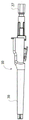
图1是根据本发明的静脉内导管设备的纵向视图;Figure 1 is a longitudinal view of an intravenous catheter device according to the present invention;
图2是本发明的静脉内导管设备的纵向截面视图;Figure 2 is a longitudinal cross-sectional view of the intravenous catheter device of the present invention;
图3是根据图2的无针盖的纵向截面视图;Figure 3 is a longitudinal sectional view of the needle-free cover according to Figure 2;
图4是根据本发明的静脉内导管设备的分解纵向截面视图;Figure 4 is an exploded longitudinal sectional view of an intravenous catheter device according to the present invention;
图5是处于缩回状态的根据本发明的静脉内导管设备的纵向截面视图;Figure 5 is a longitudinal cross-sectional view of an intravenous catheter device according to the present invention in a retracted state;
图6是根据本发明的静脉内导管设备的另一个实施例的透视分解视图;6 is a perspective exploded view of another embodiment of an intravenous catheter device according to the present invention;
图7是无张紧元件的图5的静脉内导管设备的针护罩的纵向截面视图;7 is a longitudinal cross-sectional view of the needle shield of the intravenous catheter device of FIG. 5 without a tensioning element;
图8是图7的针护罩的俯视图;Figure 8 is a top view of the needle shield of Figure 7;
图9是图7的针护罩的仰视图;并且Figure 9 is a bottom view of the needle shield of Figure 7; and
图10是图7的针护罩的远端的前视图;Figure 10 is a front view of the distal end of the needle shield of Figure 7;
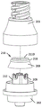
图11是根据本公开的压力启动阀的实施例的具有截面平面A-A的平面视图;11 is a plan view with cross-sectional plane A-A of an embodiment of a pressure activated valve according to the present disclosure;
图12是示出截面平面14A-14A和14B-14B的图11的俯视图;12 is a top view of FIG. 11 showing
图13是图11的实施例的分解视图;Figure 13 is an exploded view of the embodiment of Figure 11;
图14A和图14B是分别沿着截面平面14A-14A和14B-14B的图11的实施例的横截面视图;14A and 14B are cross-sectional views of the embodiment of FIG. 11 along
图15是图11的实施例的上壳体的透视图;Figure 15 is a perspective view of the upper housing of the embodiment of Figure 11;
图16是图11的实施例的下壳体的透视图;Figure 16 is a perspective view of the lower housing of the embodiment of Figure 11;
图17A和图17B是分别沿着截面平面14A-14A和14B-14B的分别处于第一操作状态和第二操作状态的图11的实施例的横截面视图;17A and 17B are cross-sectional views of the embodiment of FIG. 11 in a first operational state and a second operational state, respectively, along
图18A、图18B、图18C和图18D是根据本公开的实施例的弹性体构件的透视图;18A, 18B, 18C, and 18D are perspective views of elastomeric members according to embodiments of the present disclosure;
图19是根据本公开的压力启动阀的另一个实施例的具有截面平面B-B的平面图;19 is a plan view with cross-sectional plane B-B of another embodiment of a pressure activated valve according to the present disclosure;
图20是示出截面平面22A-22A和22A-22A的图11的俯视图;20 is a top view of FIG. 11 showing
图21A和图21B分别是图19的实施例的分解视图和分解截面视图;Figures 21A and 21B are an exploded view and an exploded cross-sectional view, respectively, of the embodiment of Figure 19;
图22A和图22B是分别沿着截面平面22A-22A和22B-22B的图19的实施例的横截面视图;22A and 22B are cross-sectional views of the embodiment of FIG. 19 along
图23A和图23B分别是图19的实施例的下壳体的平面视图和透视图;23A and 23B are a plan view and a perspective view, respectively, of the lower case of the embodiment of FIG. 19;
图24A和图24B是分别沿着截面平面22A-22A和22B-22B的分别处于第一操作状态和第二操作状态的图19的实施例的横截面视图;24A and 24B are cross-sectional views of the embodiment of FIG. 19 in a first operational state and a second operational state, respectively, along
图25A、图25B和图25C是根据本公开的压力启动阀的另一个实施例的截面视图,图25B示出了图25A旋转90°的实施例;Figures 25A, 25B and 25C are cross-sectional views of another embodiment of a pressure activated valve according to the present disclosure, Figure 25B showing the embodiment of Figure 25A rotated 90°;
图26A是根据本公开的压力启动阀的另一个实施例的具有截面平面26B-26B的平面视图;26A is a plan view with
图26B是图26A的实施例的沿着截面平面26B-26B的横截面视图;Figure 26B is a cross-sectional view of the embodiment of Figure 26A along
图27A是根据本公开的压力启动阀的另一个实施例的具有截面平面27B-27B的平面视图;27A is a plan view with
图27B是图27A的实施例的沿着截面平面27B-27B的横截面视图;Figure 27B is a cross-sectional view of the embodiment of Figure 27A along
图28A是根据本公开的压力启动阀的另一个实施例的具有截面平面28B-28B的平面视图;28A is a plan view with
图28B是图28A的实施例的沿着截面平面28B-28B的横截面视图;Figure 28B is a cross-sectional view of the embodiment of Figure 28A along
图29A是根据本公开的压力启动阀的另一个实施例的具有截面平面29B-29B的平面视图;29A is a plan view with
图29B是图29A的实施例的沿着截面平面29B-29B的横截面视图;Figure 29B is a cross-sectional view of the embodiment of Figure 29A along
图30A是根据本发明的另一个实施例的纵向截面视图;Figure 30A is a longitudinal cross-sectional view according to another embodiment of the present invention;
图30B示出了根据图30A的实施例的靠近针尖的针的细节;Figure 30B shows a detail of the needle near the tip of the needle according to the embodiment of Figure 30A;
图31A是根据本发明的又另一个实施例的纵向截面视图;并且Figure 31A is a longitudinal cross-sectional view according to yet another embodiment of the present invention; and
图31B示出了根据图31A的实施例的靠近针尖的针的细节;Figure 31B shows a detail of the needle near the needle tip according to the embodiment of Figure 31A;
图32A和图32B是根据本发明的又另一个实施例的纵向截面视图。32A and 32B are longitudinal cross-sectional views of yet another embodiment according to the present invention.
具体实施方式Detailed ways
根据本发明,提供了一种静脉内导管设备,所述静脉内导管设备提供了针对针尖意外刺伤的更好保护并且同时制造成本低廉。虽然本发明可以有许多不同形式的实施例,但是在此将描述具体实施例,应理解本公开被认为是本发明原理的例示,并且不旨在将本发明限制于本文详述的实施例中。In accordance with the present invention, there is provided an intravenous catheter device that provides better protection against accidental needle tip stick injuries and at the same time is inexpensive to manufacture. While the invention may be embodied in many different forms, specific embodiments will be described herein with the understanding that this disclosure is to be considered as illustrative of the principles of the invention and is not intended to limit the invention to the embodiments detailed herein. .
如本文所使用的,术语“近侧”是指最靠近例如使用装置的临床医生的装置的区域或装置上的位置。与此相反,术语“远侧”是指装置的距临床医生最远的区域,例如,针的远侧区域将是包含将被插入例如患者的静脉中的针尖的针的区域。As used herein, the term "proximal" refers to the area or location on the device closest to the device, eg, the clinician using the device. In contrast, the term "distal" refers to the region of the device that is furthest from the clinician, eg, the distal region of the needle would be the region of the needle that contains the needle tip to be inserted, eg, in a patient's vein.
在使用导管设备之前,针护罩被布置在靠近针轴的近端的导管座中。在这种情况下,针完全延伸穿过针护罩,从而使针护罩的第一臂向外偏转,即与轴向方向成一定角度,使得第一臂的远侧壁被支撑在针轴上。在将导管插入患者体内后,通过可从针中提供的侧向开口看得见的血液确定成功的静脉穿刺。此后,将针从导管管子抽出,并且针轴移动穿过针护罩,同时针护罩保持在导管座中。一旦针尖穿过针护罩的横向远侧壁,即,使得针轴不再支撑远侧壁,恢复力就确保针护罩的第一臂移回到与针护罩的轴向方向对齐的位置,使得针尖被针护罩的远侧壁阻挡,即,防止针尖从针护罩轴向突出。Before use of the catheter device, the needle shield is placed in the catheter hub near the proximal end of the needle shaft. In this case, the needle extends completely through the needle shield, thereby deflecting the first arm of the needle shield outward, ie at an angle to the axial direction, so that the distal wall of the first arm is supported on the needle shaft superior. After insertion of the catheter into the patient, a successful venipuncture is determined by blood visible from the lateral opening provided in the needle. Thereafter, the needle is withdrawn from the catheter tube and the needle shaft is moved through the needle shield while the needle shield remains in the catheter hub. Once the needle tip passes through the lateral distal wall of the needle shield, ie, so that the needle shaft no longer supports the distal wall, the restoring force ensures that the first arm of the needle shield moves back into alignment with the axial direction of the needle shield , so that the needle tip is blocked by the distal wall of the needle shield, ie prevents the needle tip from protruding axially from the needle shield.
一旦针尖被远侧壁阻挡,当止动元件被布置在臂之间时,针轴的扩大部与止动元件接合,或者当止动元件被布置在基部部分中时,针轴的扩大部与基部部分的远侧接合,以防止针护罩从针轴上移除。止动元件由比基部部分的第一材料更硬且更不容易变形的第二材料制成的事实具有如下效果:针护罩被更有效地固定在针轴上并且即使当拉动针时施加外力过大也可以保持原状,因为防止了扩大部由于止动元件而被拉过针护罩的基部部分。因此,针护罩不太可能意外地从针尖移除,并且因此针护罩提供了针对意外刺伤的更好保护并且因此增加了操纵导管设备的人的安全性。Once the needle tip is blocked by the distal wall, the enlarged portion of the needle shaft engages the stop element when the stop element is arranged between the arms, or the enlarged portion of the needle shaft engages with the stop element when the stop element is arranged in the base portion The distal side of the base portion engages to prevent removal of the needle shield from the needle shaft. The fact that the stop element is made of a second material that is harder and less deformable than the first material of the base part has the effect that the needle shield is more effectively fixed on the needle shaft and even if excessive force is applied when the needle is pulled The large can also remain undisturbed, since the enlargement is prevented from being pulled past the base portion of the needle shield due to the stop element. Consequently, the needle shield is less likely to be accidentally removed from the needle tip, and thus the needle shield provides better protection against accidental stick injuries and thus increases the safety of the person handling the catheter device.
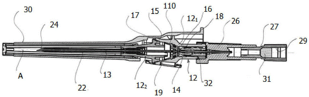
图1和图2示出了根据本发明的第一实施例的静脉内导管设备10。静脉内导管包括导管座12和在导管座12的远端处附接到导管座12的导管管子13。应当理解,术语“近侧”指的是靠近操纵静脉内导管设备的人的位置或朝向,而术语“远侧”指的是远离这个人的位置或朝向,其中针20的纵向方向A是参考方向。Figures 1 and 2 show an
导管座12的近侧部分121具有内表面14,所述内表面限定了具有大致圆形横截面的腔室16。腔室16位于导管座12的近侧区段中。在腔室16的远侧区域中,导管座的内表面14设置有环形保持突起18,将在下面进一步更详细地讨论所述环形保持突起的功能。The
导管座12还包含远侧导管座部分122。近侧导管座部分121在其远端处形成、具有锥形凹区段15。远侧导管座部分122在其近侧处形成并且具有锥形凸区段17。锥形凹区段15和锥形凸区段17形成有环形突起和凹部,所述环形突起和凹部被设置成彼此接合,以便以卡扣配合布置将近侧导管座部分121和远侧导管座部分122彼此固定在一起。固定可以通过额外的粘合剂或其它固定方式例如焊接来支撑。锥形凹区段15形成内部中空空间19,将关于阀布置进一步讨论所述内部中空空间。所述阀布置包含弹性体元件110。The catheter adapter 12 also includes a distal
具有远端和近端的针20延伸穿过导管座12的腔室16以及延伸穿过导管管子13。针20包括针轴22和在其远端处的针尖24。针座26附接到针20的近端。在近端处,针座26具有中空空间,所述中空空间收容具有通路29的塞子27,所述通路收容多孔过滤器元件31。A
针20限定所述轴向(纵向)方向A,并且除了针20在至少一个方向上的径向尺寸的扩大部之外,针轴22具有大致恒定的主轮廓,与所述主轮廓相比,所述扩大部位于针尖24的区域中并形成可以在图4中附图标记25处看到的接合器件。优选地,接合器件通过针20的卷边制成。然而,所述接合器件也可以通过针的焊接、铣削、冷镦或扩展来制造。将在下面进一步更详细地讨论接合器件的功能。The
图1、图2和图3示出了在使用前的情况下的静脉内导管设备。在使用前的这种情况下,针20一直延伸穿过导管座12的腔室16以及导管管子13,并且针尖24从导管管子13的远端突出。在这种背景下,针20的这个位置也被称为就绪位置。应注意,针20由与导管座12接合的针座26固定在其就绪位置。Figures 1, 2 and 3 show the intravenous catheter device in a condition prior to use. In this condition prior to use, the
为了防止在使用静脉内导管设备之前由针20造成的意外刺伤,管状盖30覆盖导管管子13和穿过其延伸的针20的部分。盖30的近端部分可移除地固定到导管座12的远端部分。To prevent accidental puncture by
静脉内导管设备进一步包括针护罩32,所述针护罩用于在使用针20之后,即在将导管管子13放入患者静脉和从患者静脉抽出针20之后保护针尖24。针护罩32可滑动地布置在针轴22上并收容在腔室16中。The intravenous catheter device further includes a
图4示出了具有上述部件但不是使用情况的分解视图。这个分解视图在某种程度上示出了如何可以组装根据本发明的IV导管设备的方式。Figure 4 shows an exploded view with the above components but not in use. This exploded view shows somewhat how the IV catheter device according to the present invention can be assembled.
图5示出了当针从导管座12缩回时处于缩回情况的根据本发明的这个实施例的IV导管设备。在这种情况下,针尖24被针护罩32覆盖,其中针特征25防止针护罩32在远侧方向上从针上移除。针尖24被针护罩32覆盖。可以从针座26移除塞子27。可以将导管管子13引入患者的静脉中,这未被详细示出。FIG. 5 shows the IV catheter device according to this embodiment of the invention in a retracted condition when the needle is retracted from the
图6以进一步的透视分解视图示出了整个布置。它还示出了用于固定导管管子13的中空固定塞子31。Figure 6 shows the entire arrangement in a further perspective exploded view. It also shows a hollow fixing
如可以在图7到图10中更详细地看到的,针护罩32包括管状基部部分34以及大致在轴向方向上从管状基部部分34的远侧延伸的第一臂36和第二臂38。基部部分34和臂36、38由塑料材料一体地制成,例如通过注塑模制。As can be seen in more detail in FIGS. 7-10 , the
基部部分34具有用于收容针20的轴向通孔40。通孔40包括第一区段42和第二区段44两者,所述第一区段和所述第二区段的横截面大于针20的主轮廓,第二区段44的横截面甚至大于第一区段42的横截面。The
呈盘状板形状的止动元件46如垫圈例如通过嵌件模制布置在基部部分34的远侧处。止动元件46由与基部部分34的材料不同的材料制成,例如由金属材料制成。止动元件46具有轴向孔48,所述轴向孔与基部部分34的通孔40对齐并且其横截面小于基部部分34的通孔40的横截面。更具体地,止动元件46的轴向孔48的横截面适合于针20的主轮廓,使得止动元件46可以以最小摩擦力沿着针轴22滑动。然而,横向于纵向方向A的轴向孔48的最大尺寸小于横向于纵向方向设置在针20上的接合器件的最大尺寸,以防止接合器件穿过止动元件46并且因此防止针护罩32从针20上滑落。A
针护罩32的第一臂36比第二臂38长,并且具有大的远端区段50,所述远端区段具有用于捕获针尖24的底切部51。远端区段50朝向第二臂38成角度并与第二臂38重叠(图8)。在其就绪位置中,针20完全延伸穿过针护罩32(图7)。在这种情况下,第一臂38的远端区段50被支撑在针轴22上,从而使第一臂36径向地向外偏转。为了便于第一臂36偏转,第一臂36具有大致在臂36的中间区域中的横截面减小的变窄部分52。与第一臂36相反并且由于缺少成角度的远端区段,第二臂38不会被延伸穿过针护罩32的针20显著偏转。尽管如此,第二臂38具有类似的变窄部分54,其原因将在下面进一步变得显而易见。The
即使第一臂36和第二臂38具有一定弹性,张紧元件例如橡胶带56(由图8和图9中的虚线表示)围绕臂36、38的远端区段,使得第一臂36的偏转主要发生在张紧元件的恢复力上(图7)。Even though the
当在将导管13放入患者静脉中之后将针20从导管管子13中抽出时,针20滑过针护罩32直到针尖24穿过第一臂36的成角度的远端区段50。此时,成角度的远端区段50不再支撑在针轴22上,并且第一臂36-主要通过由橡胶带56支撑的自身弹性力-用正在阻挡针尖24的成角度的远端区段50卡扣回到其松弛状态。应当理解,第一臂36的长度和接合器件距针尖24的距离彼此适配,使得收容在针护罩32中的针尖24相对于在针护罩32中的轴向移动具有最小间隙。When the
为了防止针护罩32过早地从导管座12的腔室16移除,即在针尖24被针护罩32覆盖之前,第一臂36设置有盘状第一保持突起58,所述第一保持突起在第一臂36的偏转状态下与导管座14的内表面14中的保持凹陷18接合。第一保持突起58具有大致平坦的近侧面60、远侧面62和凸的,具体地是部分圆柱形的外周表面64,其半径与保持凹陷18的区域中的导管座12的内表面14的半径相适配。第一保持突起58的高度,即在径向方向上看到的其尺寸,被适配成使得当第一臂36卡扣回到其松弛状态时第一保持突起58与保持凹陷18脱离接合。In order to prevent premature removal of the
第二臂38设置有盘状第二保持突起66,所述第二保持突起类似于第一保持突起58并且在与第一保持突起58相反的径向方向上延伸。第二保持突起66还具有大致平行的近侧面60和远侧面62以及凸的,具体地是部分圆柱形的外周表面64。第二保持突起66的高度,即在径向方向上看到的其尺寸,被适配成使得当针20处于其就绪位置时保持突起66与保持凹陷18接合。为了使保持突起66与保持凹陷18脱离接合,当针20上的拉力变得足够大时,第二臂38可以朝向针20在径向上向内略微偏转。The
如从图1中可以看出,保持凹陷18的轴向尺寸即宽度显著大于保持突起58、66的轴向尺寸,即宽度。例如,尽管其它比率是可能的,但是只要确保保持凹陷18与保持突起58、66之间的可靠接合,保持凹陷18的宽度就可以是保持突起58、66的宽度的三倍到五倍。As can be seen in FIG. 1 , the axial dimension, ie the width, of the retaining
如上所述,IV导管装置还包含阀。为了解释阀的结构和功能,参考图11到图29B了解可以整合到IV导管中的阀的不同实施例。阀可以如下所讨论的单独形成或整合在导管装置中。因此,阀被单独地描述为装置100。如上所示,阀可以整合到导管座12中,所述导管座然后与至少两个导管座部分121和122形成阀的壳体。As mentioned above, the IV catheter set also includes a valve. To explain the structure and function of the valve, reference is made to Figures 11-29B for various embodiments of valves that may be integrated into an IV catheter. The valve may be formed separately or integrated into the catheter device as discussed below. Accordingly, the valve is described solely as
现在参考附图,图11是描绘将阀形成为单独的部件的装置100的第一实施例的透视图。装置100包括用于提供与凸形鲁尔配件连接的刚性上壳体101以及提供与凹形鲁尔配件连接的刚性下壳体102。所述装置具有光滑外部以让患者感到舒适。装置100具有第一开口101a和第二开口102a。虽然第一开口101a被示出为带螺纹的,但是它可以被配置成光滑的而不具有螺纹。图12是装置100的俯视图,其示出了在下面进一步描述的截面平面。Referring now to the drawings, FIG. 11 is a perspective view depicting a first embodiment of an
图13是装置100的分解透视图,其描绘了具有支撑件112的下壳体102、具有从表面167朝向下壳体102突出的外周壁169的弹性体构件110。表面167上存在狭缝117。上壳体101被配置成与下壳体102形成不透流体的密封。如图所示,上壳体101可以配置有带螺纹的凹形鲁尔配件106。如图所示,下壳体可以配置有凸形鲁尔配件107和周围的内螺纹108。13 is an exploded perspective view of
现在参考图14A和图14B,示出了处于经组装构型的第一实施例装置100的分别相隔90°的横截面视图。Referring now to FIGS. 14A and 14B , cross-sectional views, respectively, 90° apart, of the
图14A描绘了弹性体构件110的外周壁169的一部分,所述外周壁与内壁111过盈配合,从而与上壳体101的内壁111形成连续密封件。弹性体构件110将装置100分成对应于第一开口101a的上部区段和对应于第二开口102a的下部区段。弹性体构件110被示出为由支撑件112支撑。支撑件112形成开口109并在下壳体102与第二开口102a之间提供流体连通。弹性体构件110在此被示出为常闭阀,因为狭缝117和与内壁111形成的连续密封件两者在装置100通过压差启动之前防止流体在开口101a与开口102a之间流动。在制造期间固定上壳体101和下壳体102时,例如在将壳体部件一起粘接/焊接在例如焊接接头114处时,可以提供弹性体构件110与壳体的内壁111之间的过盈配合。弹性体构件由支撑件112支撑,并且弹性体构件抵靠上壳体的内壁111密封。流体能够在支撑件之间流入开口109中并通过第一开口101a。下壳体102包含围绕突出部102c的基部102e,所述突出部从基部102e突出作为第二开口102a的一部分。表面(或基部)102e径向向外延伸到渐缩壁102d。渐缩壁102d的外径的一部分被配置成通过焊接接头114可密封的具有上壳体101的内径的布置。FIG. 14A depicts a portion of the outer
图14B描绘了第一实施例的一方面,由此流体通道115c被设置在上壳体101的内壁111中。如图所示,流体通道115c大致平行于装置100的纵向轴线朝向下壳体102延伸。流体通道115c的长度的远侧终点(例如,远端115d)被配置成使得外周壁169的至少一部分(例如,如图所示,远端169a)与内壁111持续地保持过盈。在一个实施例中,装置100可以配置成没有流体通道115c(宽度等于0)。FIG. 14B depicts an aspect of the first embodiment whereby
在一方面,两个或更多个流体通道115c被设置在上壳体101的内壁111中。在这种方面,两个流体通道115c可以以与其基本上与装置100的纵向轴线对齐的对应纵向轴线平行的构型布置。在一个实施例中,弹性体构件具有由单个狭缝形成的狭缝117,并且两个流体通道115c被布置成与单个狭缝117的纵向轴线正交。在这种构型中,在输注流体期间并且在外周壁169偏转时,径向力被施加到表面167,以便于维持狭缝117闭合。In one aspect, two or more
图15示出了上壳体101的透视图,其描述了如图所示与第一开口101a流体连通并且具有大致平行于上壳体101的纵向轴线的长度的流体通道115c。流体通道115c的宽度可以被选择为大约等于大于零且小于上壳体101的最大内部周长的一半的数量的任何宽度。在一方面,流体通道115c的宽度被选择为小于第一开口101a的最小内径,以便在输注和/或冲洗装置100期间促进压力或力(和/或加速流体速度)聚焦在外周壁169上。图16示出了下壳体102的透视图,其描绘了围绕第二开口102a的突出部102c布置的多个支撑件112。支撑件112围绕突出部102c径向布置,其间具有间隔,以允许在输注期间上壳体101第一开口101a与下壳体102第二开口102a之间的流体连通。支撑件112可以具有远侧突出部112c,所述远侧突出部被配置成接触弹性体构件110的下表面并且在组装或使用期间使弹性体构件110在壳体内的移位最小化和/或施加预载荷和/或考虑上壳体部件和下壳体部件的堆叠。15 shows a perspective view of the
图17A和图17B是分别以第一状态(例如,输注)和第二状态(例如,抽吸)示出的装置100的横截面视图。箭头A1和A2描绘了装置100内的流体流动方向。17A and 17B are cross-sectional views of
参考图17A,在第一状态下,在通过第一开口101a输注流体时产生了在分隔壳体之间的压差,所述压差引起外周壁169从上壳体101的内壁111偏转,从而产生流体通路115并允许围绕弹性体构件110在装置100的上部部分与下部部分之间流体连通,同时保持狭缝117闭合,以便提供从第一开口101a到第二开口102a的定向流体流动。下壳体102的结构,例如渐缩壁102d和突出部102c,可以提供湍流和/或流体流动方向,以便能够有效地冲洗已经与体液接触的弹性体构件部分(例如,外周壁169的内表面)。在各个方面的外周壁169提供椭圆形、杯状或截头圆锥形(或截头圆锥形),所述椭圆形、杯状或截头圆锥形被配置成在产生压差时以相对低的输注开启压力阈值朝向装置100的中心纵向轴线向内偏转和/或弯曲(例如通过将输注流体引入开口101a)。相对低的输注开启压力阈值为H20的约6英寸到约36英寸(0.2 psig到约1.3 psig;其中术语“约”涵盖所述值的±20%)。例如,当IV袋升高到患者中的插入点的高度以上时,获得这种压力。与在输注状态和抽吸状态下流动“穿过”弹性体密封件/阀的现有阀不同,当前公开的阀被配置成在输注状态下“围绕”阀流动并且在抽吸状态下流动通过阀。这种当前构型的优点在于,抽吸后的泄漏和“回流”几乎全部被消除,并且如参照图17A和图17B的示例性实施例所述的,提供了通过重力容易地输注流体的期望能力。Referring to FIG. 17A , in the first state, a pressure difference between the partition housings is generated when the fluid is infused through the
参考图17B,在第二状态下,在通过第二开口102a抽吸流体时产生的压差导致狭缝117打开,而外周壁169的远端169a保持与上壳体101的内壁111持续可密封过盈接触。在一方面,狭缝被配置成使得需要抽吸压力阈值以允许流体从第二开口102a穿过狭缝穿过第一开口101a。在一方面,抽吸压力阈值显著高于输注开启压力阈值。在一方面,抽吸压力阈值与输注抽吸阈值之间的差异使得抽吸阈值开启压力比输注阈值开启压力大约5 psig。阈值开启压力的这种差异的范围可以在约3 psig与约7 psig之间(其中“约”涵盖所述值的±20%)。配置阈值开启压力的差异可以通过改变下面进一步讨论的弹性体构件110的弹性模量、厚度和/或厚度变化、锥度、交联/固化以及材料选择和尺寸以及狭缝117的设计和布置来实现。可以关于开启压力阈值调节的附加参数包含流动通道115c的数量、宽度和长度和/或上壳体部件和下壳体部件的内部几何形状。Referring to FIG. 17B , in the second state, the pressure differential created when fluid is drawn through the
参考图18A、图18B、图18C和图18D,示出了弹性体构件的变型。图18A和图18B描绘了具有单个狭缝117和多狭缝117a构型的弹性体构件110。可以使用其它狭缝构型。Referring to Figures 18A, 18B, 18C and 18D, variations of the elastomeric member are shown. Figures 18A and 18B depict
图18C和图18D分别描绘了改进的弹性体构件110a和110b,所述弹性体构件在示例性截头圆锥形构件110a、110b上具有附加特征,即截头圆锥形构件110a的表面上的突出部1100、或截头圆锥形构件110b的表面中的一个或多个通道1150。Figures 18C and 18D depict improved
图18D进一步描绘了弹性体构件的实施例,其中截头圆锥形构件110b包含杆部1175,所述杆部具有穿过其、由外周壁169c包围的管道(未示出),所述管道被配置成围绕第二开口102a或牢固地包围下壳体101的突出部102c。杆部1175可以被配置为用于与开口102a和狭缝117流体连通的管道。在这种构型中,杆部1175必然包括一个或多个竖直布置(具有壳体纵向轴线)的开口/狭缝(未示出),所述开口/狭缝穿过其以在输注期间用于流体通路/冲洗,所述开口/狭缝可以被配置成响应压缩输注压力/力并且至少部分地打开以允许流体进入开口102a,而在抽吸期间,不经受压缩应力的开口/狭缝将保持关闭以便于基本上所有流体流过开口102a、杆部1175、狭缝117、壳体的上部区段和开口101a。在上述弹性体构件实施例的这种改进中,将保持如上所述的弹性体构件110的所有其它功能属性。Figure 18D further depicts an embodiment of an elastomeric member in which the
参照图19,示出了当前公开的阀的第二实施例,其描绘了装置200的透视图,所述装置具有带有第一开口201a的上壳体201和下壳体202。Referring to Figure 19, a second embodiment of the presently disclosed valve is shown, depicting a perspective view of a
图20描绘了具有截面平面22A-22A和22B-22B的装置200的俯视图。20 depicts a top view of
图21A和图21B分别描绘了装置200的分解视图和分解截面视图。装置200的下壳体202包含环形壁212。在此示例性实施例中,环形壁212为弹性体构件210提供支撑,所述弹性体构件被外周壁269包围。如图所示,环形壁212可以与下壳体201成一体,或者可以单独模制并且在组装期间布置在壳体中。弹性体构件210具有来自表面267的边缘的侧向环形突起218,所述环形突起被配置成由上壳体201的内壁211内的凹部218a收容。此外,弹性体构件210包含来自表面267的用于在组装上壳体部件201和下壳体部件202时提供过盈的竖直环形凸起2110。弹性体构件210的表面267包含狭缝217,所述狭缝穿过表面267的厚度。与前一实施例不同,装置200的下壳体202包含进给到第二开口202a中的渐缩开口202c。渐缩开口202c提供用于将医疗装置如导丝等插入到较小直径的第二开口201a中的引导,并且防止这种装置的扭结和/或弯曲。21A and 21B depict an exploded view and an exploded cross-sectional view of the
现在参考图22A和图22B,示出了处于经组装构型的分别相隔90°的第二实施例装置200的横截面视图。图22A描绘了弹性体构件210的外周壁269的一部分,所述外周壁与内壁211过盈配合,从而与上壳体201的内壁211形成连续密封件。弹性体构件210将装置200分成对应于第一开口201a的上部区段和对应于第二开口202a的下部区段。弹性体构件210被示出为由环形突出部212支撑,所述环形突出部包含在下壳体202与第二开口202a之间提供流体连通的流动通路209。弹性体构件210在此被示出为常闭阀,因为狭缝217和与内壁211形成的连续密封件两者在装置200通过压差启动之前防止流体在开口201a与开口202a之间流动。在制造期间固定上壳体201和下壳体202时,例如在将壳体部件一起粘接/焊接在例如焊接接头214处时,可以提供弹性体构件210与壳体内壁211之间的过盈配合。弹性体构件210的外周壁269与内壁211形成流体型密封。流体能够流过开口209处的环形支撑件212和第二开口202a。下壳体202包含围绕环形支撑件212的表面或基部202e,所述环形支撑件从基部202e突出作为第二开口202a的一部分。表面或基部202e径向向外延伸到渐缩壁202d。渐缩壁202d的外径的一部分被配置成通过焊接接头214可密封的具有上壳体201的内径的布置。图22B描绘了第二实施例的一方面,由此环形支撑件212的内径向内渐缩成第二开口202a的内径的尺寸,所述第二开口还用作用于可以插入穿过所述装置的医疗装置的引导器件。Referring now to Figures 22A and 22B, there are shown cross-sectional views of the
以类似于第一实施例的方式,装置200包括任选的流体通道215c,所述流体通道大致平行于装置200的纵向轴线朝向下壳体202延伸。在一个实施例中,本文公开的装置中的任一个可以被配置成没有流体通道215c。In a manner similar to the first embodiment, the
图23A示出了下壳体202的侧视图,其描绘了环形支撑件212和通路209。图23B是下壳体202的透视图,其示出了环形支撑件212和进给到第二开口202a中的渐缩的开口202f。环形支撑件212可以具有远侧突出部212c,所述远侧突出部被配置成接触弹性体构件210的下表面并且在组装或使用期间使弹性体构件210在壳体内的移位最小化。FIG. 23A shows a side view of
装置200类似地起到第一实施例的装置的作用,如图24A和图24B所描绘的,其分别示出了以第一状态(例如,输注)和第二状态(例如,抽吸)示出的装置200的横截面视图。箭头Bl和B2描绘了装置200内的流体流动方向。参考图24A,在第一状态下,在通过第一开口201a输注流体时在装置200的分隔壳体之间产生压差,所述压差引起外周壁269从上壳体201的内壁211偏转,从而产生流体通路215并允许围绕弹性体构件210在装置200的上部部分与下部部分之间流体连通,同时保持狭缝217闭合,以便提供从第一开口201a到第二开口202a的定向流体流动。下壳体202的结构例如渐缩的壁202d可以提供湍流和/或流体流动方向,以便能够有效地冲洗已经与体液接触的弹性体构件部分(例如,外周壁269的内表面)。外周壁269被配置成在产生压差时以如前第一实施例所述的相对低的输注开启压力阈值朝向装置200的中心纵向轴线向内偏转和/或向内弯曲(例如通过将输注流体引入开口201a)。参考图24B,在第二状态下,在通过第二开口202a抽吸流体时产生分隔壳体中的压差,所述压差导致狭缝217打开,而外周壁269的远侧边缘269a保持与上壳体201的内壁211持续可密封过盈接触。在一方面,狭缝被配置成使得需要抽吸压力阈值以允许流体从第二开口202a穿过狭缝穿过第一开口201a。
图25A和图25B描绘了第三实施例装置300,所述第三实施例装置被示出为配置有来自第二实施例装置200的上壳体201和弹性体构件210,而具有开口309的环形支撑件312被配置成不接触弹性体构件210的下表面。如上所讨论的,弹性体构件210的支撑仅由侧向环形突起218提供且与凹部218a过盈。图25C描绘了具有对装置300的下壳体部件进行的修改的装置333,其中环形支撑件312完全不存在,并且下壳体302'的表面或基部302e具有开口302c以进给到第二开口302a中。FIGS. 25A and 25B depict a
图26A和图26B是沿着第四实施例装置400的截面平面26B-26B的透视图和横截面视图,其示出了具有凸形鲁尔锁壳体组合件的压力启动阀的实施方式。管401a结合到管壳体401,所述管壳体连接到凸形鲁尔壳体402。凸形鲁尔锁座402c卡扣配合到下壳体402。装置400的功能和操作与前面描述的实施例类似地描述。26A and 26B are perspective and cross-sectional views along
图27A和图27B分别是组装有上壳体201的第五实施例装置500的沿着截面平面27B-27B的透视图和横截面视图。装置500展示了压力启动阀如何可以直接整合到血管导管座502中。导管502a可以是外周IV导管、PICC、CVC等。如上所示并且关于图1到图9所讨论的,根据本发明的IV导管另外设置有用于防止意外的刺伤的针护罩。27A and 27B are perspective and cross-sectional views, respectively, of the
图28A和图28B分别是组装有上壳体201并且进一步与凸形鲁尔装置650联接的第五实施例装置600的沿着截面平面28B-28B的透视图和横截面视图。装置600展示了弹性体构件210的狭缝217如何可以适应通过导管602a插入、由渐缩的内部管道602e引导的医疗装置675。FIGS. 28A and 28B are perspective and cross-sectional views, respectively, of the
图29A和图29B分别是第六实施例装置700的沿着截面平面29B-29B的透视图和横截面视图。装置700展示了直接与鲁尔致动阀701整合的本公开的压力启动阀。压力启动阀组合件在727处连接到鲁尔致动阀组合件。鲁尔致动阀701组装到凹形鲁尔壳体703中并在728处密封在其内。如所示的包括鲁尔致动阀的装置700是一个阀的实例,然而,压力启动阀组合件可以与任何数量的鲁尔致动阀整合,以提供如本文所公开的益处。29A and 29B are perspective and cross-sectional views, respectively, of
图30A和图30B、图31A和图31B以类似于根据图4的视图的分解视图示出了根据本发明的另一个实施例。不同之处在于针包含在针特征25稍微近侧的通孔,所述通孔形成为狭缝70。狭缝70在横向方向上延伸到针的纵向轴线A。狭缝70提供如在说明书的介绍部分中描述的闪回特征。Figures 30A and 30B, 31A and 31B show another embodiment according to the invention in an exploded view similar to the view according to Figure 4 . The difference is that the needle contains a through hole slightly proximal of the
需要补充的是,关于具有针护罩32的安全IV导管的不同实施例的本发明以及根据阀装置的描述的参考图11到图29的压力启动阀,上壳体101、201、701可以由近侧导管座部分121形成,并且下壳体102、202、302、402、502、602可以由远侧导管座部分122形成。还可以将如例如关于图11描述的单独的阀装置与仍由本发明覆盖的安全IV导管组合。It should be added that with regard to the invention of the different embodiments of the safety IV catheter with the
图32A和图32B示出了本发明的另一个实施例。不同之处在于端口71在大致垂直于轴向方向A的方向上从导管座121的主体延伸。提供了用于覆盖端口71的帽73。翼72被设置在与端口71相对的主体处。Figures 32A and 32B illustrate another embodiment of the present invention. The difference is that the
应当理解,尽管本文中可以使用术语第一、第二等来描述各种元件,但是这些元件不应受这些术语的限制。这些术语仅用于将一个元件与另一个元件相区分。例如,在不偏离本公开的范围的情况下,第一元件可以被称为第二元件,并且类似地,第二元件可以被称为第一元件。如本文所使用的,术语“和/或”包含相关联的所列项中的一个或多个任何和所有组合。It will be understood that, although the terms first, second, etc. may be used herein to describe various elements, these elements should not be limited by these terms. These terms are only used to distinguish one element from another. For example, a first element could be termed a second element, and, similarly, a second element could be termed a first element, without departing from the scope of the present disclosure. As used herein, the term "and/or" includes any and all combinations of one or more of the associated listed items.
在本文中可以使用如“下方(below)”或“上方(above)”或“上部(upper)”或“下部(lower)”或“水平”或“竖直”等相对术语来描述如图所示的一个元件、层或区域与另一个元件、层或区域的关系。应当理解,除了附图中所描绘的朝向之外,这些术语旨在涵盖装置的不同朝向。Relative terms such as "below" or "above" or "upper" or "lower" or "horizontal" or "vertical" may be used herein to describe The relationship of one element, layer or region shown to another element, layer or region. It should be understood that these terms are intended to encompass different orientations of the device in addition to the orientation depicted in the figures.
在此所使用的术语用于以下目的:仅描述具体实施例并且不旨在限制本公开。如在此使用的,单数形式“一个”、“一种”、和“该”旨在还包括复数形式,除非文中相反地清楚指出。The terminology used herein is used for the purpose of describing particular embodiments only and is not intended to limit the present disclosure. As used herein, the singular forms "a," "an," and "the" are intended to include the plural forms as well, unless the context clearly dictates otherwise.
应进一步理解的是,当在本文中使用时,术语“包括(comprises)”,“包括(comprising)”,“包含(includes)”和/或“包含(including)”指定所述特征、整数、步骤、操作、元件和/或部件的存在,但是不排除存在或添加一个或多个其它特征、整数、步骤、操作、元件、部件和/或其组,除非另有定义,否则本文中使用的所有术语(包含技术术语和科技术语)具有与本公开所属领域的普通技术人员通常所理解的含义相同的含义。应进一步理解的是,本文所使用的术语应被解释为具有与其在本说明书和相关领域的上下文中的含义一致的含义,并且除非本文中明确地如此定义,否则将不会在理想化的或过度正式的意义上进行解释。It is to be further understood that the terms "comprises", "comprising", "includes" and/or "including" as used herein designate the stated features, integers, The presence of steps, operations, elements and/or components, but does not preclude the presence or addition of one or more other features, integers, steps, operations, elements, components and/or groups thereof, unless otherwise defined, as used herein All terms (including technical and scientific terms) have the same meaning as commonly understood by one of ordinary skill in the art to which this disclosure belongs. It is to be further understood that terms used herein are to be construed to have the meanings consistent with their meanings in the context of this specification and related art and, unless explicitly so defined herein, will not be used in idealized or Explain in an overly formal sense.
除非另有明确说明,否则如“较少”和“较大”等比较性定量术语旨在涵盖平等概念。例如,“较少”可能不仅意味着在最严格的数学意义上“较少”,而且还意味着“小于或等于”。如本文所使用的术语“流体”是指液体、气体或其组合。Comparative quantitative terms such as "less" and "larger" are intended to cover the concept of equality unless explicitly stated otherwise. For example, "less" might not only mean "less" in the strictest mathematical sense, but also "less than or equal to". The term "fluid" as used herein refers to a liquid, a gas, or a combination thereof.
Claims (45)
Applications Claiming Priority (3)
| Application Number | Priority Date | Filing Date | Title |
|---|---|---|---|
| IN201611026278 | 2016-08-01 | ||
| IN201611026278 | 2016-08-01 | ||
| PCT/IB2017/050499 WO2018025094A1 (en) | 2016-08-01 | 2017-01-31 | Intravenous catheter apparatus with safety function and pressure controlled valve element |
Publications (2)
| Publication Number | Publication Date |
|---|---|
| CN109789291A CN109789291A (en) | 2019-05-21 |
| CN109789291B true CN109789291B (en) | 2022-05-03 |
Family
ID=58185564
Family Applications (1)
| Application Number | Title | Priority Date | Filing Date |
|---|---|---|---|
| CN201780060096.2A Active CN109789291B (en) | 2016-08-01 | 2017-01-31 | Intravenous catheter apparatus with safety function and pressure control valve element |
Country Status (12)
| Country | Link |
|---|---|
| US (2) | US11116944B2 (en) |
| EP (2) | EP3341066B1 (en) |
| JP (1) | JP7257318B2 (en) |
| CN (1) | CN109789291B (en) |
| AU (1) | AU2017306658B2 (en) |
| BR (1) | BR112019002082B1 (en) |
| ES (1) | ES2905900T3 (en) |
| MY (1) | MY197406A (en) |
| RU (1) | RU2742869C2 (en) |
| SG (1) | SG11201900903SA (en) |
| WO (1) | WO2018025094A1 (en) |
| ZA (1) | ZA201900873B (en) |
Families Citing this family (27)
| Publication number | Priority date | Publication date | Assignee | Title |
|---|---|---|---|---|
| SG11201900903SA (en) * | 2016-08-01 | 2019-02-27 | Poly Medicure Ltd | Intravenous catheter apparatus with safety function and pressure controlled valve element |
| ES2955558T3 (en) | 2016-10-27 | 2023-12-04 | Bard Inc C R | Intraosseous access device |
| CA3047165A1 (en) | 2016-12-27 | 2018-07-05 | Vasonics, Llc | Catheter housing |
| CN112120742B (en) * | 2019-06-25 | 2025-06-13 | 杭州德柯医疗科技有限公司 | Piercing device |
| EP4028104A4 (en) | 2019-09-10 | 2023-12-13 | MedSource International LLC | An intravenous catheter device |
| CN212879457U (en) | 2019-09-27 | 2021-04-06 | 巴德阿克塞斯系统股份有限公司 | Self-advancing intraosseous access device and intraosseous access device |
| EP4031027B1 (en) | 2019-09-27 | 2024-10-30 | Bard Access Systems, Inc. | Various operating mechanisms for intraosseous access medical devices |
| US11759235B2 (en) | 2019-09-27 | 2023-09-19 | Bard Access Systems, Inc. | Constant-torque intraosseous access devices and methods thereof |
| CN112568962A (en) | 2019-09-27 | 2021-03-30 | 巴德阿克塞斯系统股份有限公司 | Stepped needle for an intraosseous access device |
| JP7512300B2 (en) | 2019-12-24 | 2024-07-08 | ポリー メディキュア リミテッド | Intravenous Catheter Device |
| US11291801B2 (en) | 2020-01-31 | 2022-04-05 | Np Medical Inc. | Patient access site securement system |
| CN113317840A (en) | 2020-02-28 | 2021-08-31 | 巴德阿克塞斯系统股份有限公司 | Flexible intra-osseous obturator |
| US11896264B2 (en) | 2020-04-21 | 2024-02-13 | Bard Access Systems, Inc. | Reusable push-activated intraosseous access device |
| AU2021264445B2 (en) * | 2020-04-27 | 2025-09-25 | Bard Access Systems, Inc. | Preloaded stylet valve compatibility |
| CN113749724B (en) | 2020-06-03 | 2026-01-13 | 巴德阿克塞斯系统股份有限公司 | Intraosseous device including sensing obturator |
| CN113940727A (en) | 2020-07-17 | 2022-01-18 | 巴德阿克塞斯系统股份有限公司 | Safety mechanism |
| CN114098918B (en) | 2020-08-25 | 2025-12-12 | 巴德阿克塞斯系统股份有限公司 | Angled intraosseous access system |
| EP4203820B1 (en) | 2020-09-09 | 2025-01-29 | Bard Access Systems, Inc. | Aspiration apparatus for intraosseous access system |
| US11779750B2 (en) * | 2020-09-29 | 2023-10-10 | Carefusion 303, Inc. | Needleless connector with valve pivot support |
| CN217960227U (en) | 2021-02-08 | 2022-12-06 | 巴德阿克塞斯系统股份有限公司 | Intraosseous access system |
| WO2022172281A1 (en) * | 2021-02-10 | 2022-08-18 | Neeraj Gupta | Intravenous cannula |
| US12337123B2 (en) | 2021-05-06 | 2025-06-24 | Medsource Labs, Llc | Safety intravenous cannula |
| US20220379095A1 (en) * | 2021-05-27 | 2022-12-01 | Becton, Dickinson And Company | Needle assembly for visualization of fluid movement |
| CN115671492A (en) * | 2021-07-27 | 2023-02-03 | 上海微创生命科技有限公司 | Two-way valve, two-way valve assembly and PICC catheter |
| US12186497B2 (en) | 2022-01-14 | 2025-01-07 | Medsource International Llc | Intravenous cannula |
| US20240100300A1 (en) * | 2022-09-27 | 2024-03-28 | Carefusion 303, Inc. | Fluid shield assemblies and flow restriction devices with fluid shield assemblies |
| CN119633204B (en) * | 2025-01-17 | 2025-09-16 | 中国人民解放军空军军医大学 | Sleeves and injection components for local anesthetic injection |
Citations (3)
| Publication number | Priority date | Publication date | Assignee | Title |
|---|---|---|---|---|
| US5603702A (en) * | 1994-08-08 | 1997-02-18 | United States Surgical Corporation | Valve system for cannula assembly |
| CN104684478A (en) * | 2012-08-27 | 2015-06-03 | 英杰克蒂姆梅德公司 | needle cover |
| CN105396212A (en) * | 2014-04-29 | 2016-03-16 | B.布劳恩梅尔松根股份公司 | Valved Catheter Assemblies And Related Methods |
Family Cites Families (22)
| Publication number | Priority date | Publication date | Assignee | Title |
|---|---|---|---|---|
| US4332249A (en) * | 1980-08-01 | 1982-06-01 | Sherwood Medical Industries, Inc. | Filter and valve assembly for hypodermic syringe |
| DE3721299A1 (en) * | 1987-06-27 | 1989-01-12 | Braun Melsungen Ag | CATHETER DEVICE |
| US4827973A (en) | 1988-06-27 | 1989-05-09 | Vernay Laboratories, Inc. | One way flow valve |
| DE20210394U1 (en) | 2002-07-04 | 2002-09-12 | B. Braun Melsungen Ag, 34212 Melsungen | catheter introducer |
| US7601141B2 (en) | 2002-11-26 | 2009-10-13 | Nexus Medical, Llc | Pressure actuated flow control valve |
| US7988679B2 (en) | 2003-03-18 | 2011-08-02 | Navilyst Medical, Inc. | Pressure responsive slit valve assembly for a plurality of fluids and uses thereof |
| US7914502B2 (en) | 2003-07-31 | 2011-03-29 | Nypro Inc. | Anti-drawback medical valve |
| US8308691B2 (en) * | 2006-11-03 | 2012-11-13 | B. Braun Melsungen Ag | Catheter assembly and components thereof |
| CN101104094A (en) * | 2007-08-10 | 2008-01-16 | 张亚根 | Safety type artery and venous indwelling needle with airtight interface without needle |
| JP5889277B2 (en) * | 2010-04-16 | 2016-03-22 | ポリー メディキュア リミテッド | Catheter device |
| UA110794C2 (en) * | 2010-05-05 | 2016-02-25 | Полі Медікьюе Лімітед | Protective device for medical needles instruments and node iv catheter comprising said needle protective device |
| CN106943647B (en) * | 2010-08-05 | 2020-09-04 | B·布朗·梅尔松根有限公司 | Needle safety device and assembly |
| US9623210B2 (en) * | 2013-03-15 | 2017-04-18 | B. Braun Melsungen Ag | Catheter assemblies with wipeable bloodstop and related methods |
| US8979802B2 (en) * | 2013-03-15 | 2015-03-17 | B. Braun Melsungen Ag | Safety IV catheter assembly with seal |
| CN203694357U (en) | 2013-03-15 | 2014-07-09 | B.布劳恩梅尔松根股份公司 | safety IV catheter |
| US9114231B2 (en) * | 2013-03-15 | 2015-08-25 | B. Braun Melsungen Ag | Valved catheter assemblies and related methods |
| JP6298146B2 (en) * | 2013-03-16 | 2018-03-20 | ポリー メディキュア リミティド | Transfer device valve |
| CN106456958B (en) * | 2014-01-08 | 2021-04-02 | B.布劳恩梅尔松根股份公司 | Catheter device with valve and related method |
| US9750925B2 (en) * | 2014-01-21 | 2017-09-05 | Becton, Dickinson And Company | Ported catheter adapter having combined port and blood control valve with venting |
| BR112017002254B1 (en) * | 2014-08-05 | 2023-02-07 | Bullpup Scientific Ltd | CATHETER INSERTION SYSTEM AND CATHETER CLOSURE UNIT |
| KR101618028B1 (en) * | 2015-11-30 | 2016-05-18 | 최영철 | Assembled filter for syringe, syringe and assembled ringer comprising thereof |
| SG11201900903SA (en) * | 2016-08-01 | 2019-02-27 | Poly Medicure Ltd | Intravenous catheter apparatus with safety function and pressure controlled valve element |
-
2017
- 2017-01-31 SG SG11201900903SA patent/SG11201900903SA/en unknown
- 2017-01-31 MY MYPI2019000617A patent/MY197406A/en unknown
- 2017-01-31 EP EP17707667.6A patent/EP3341066B1/en active Active
- 2017-01-31 EP EP21212032.3A patent/EP3998098A1/en active Pending
- 2017-01-31 WO PCT/IB2017/050499 patent/WO2018025094A1/en not_active Ceased
- 2017-01-31 ES ES17707667T patent/ES2905900T3/en active Active
- 2017-01-31 RU RU2019105210A patent/RU2742869C2/en active
- 2017-01-31 CN CN201780060096.2A patent/CN109789291B/en active Active
- 2017-01-31 US US15/768,754 patent/US11116944B2/en active Active
- 2017-01-31 JP JP2019505503A patent/JP7257318B2/en active Active
- 2017-01-31 BR BR112019002082-9A patent/BR112019002082B1/en active IP Right Grant
- 2017-01-31 AU AU2017306658A patent/AU2017306658B2/en active Active
-
2019
- 2019-02-11 ZA ZA2019/00873A patent/ZA201900873B/en unknown
-
2021
- 2021-09-10 US US17/472,346 patent/US12029869B2/en active Active
Patent Citations (3)
| Publication number | Priority date | Publication date | Assignee | Title |
|---|---|---|---|---|
| US5603702A (en) * | 1994-08-08 | 1997-02-18 | United States Surgical Corporation | Valve system for cannula assembly |
| CN104684478A (en) * | 2012-08-27 | 2015-06-03 | 英杰克蒂姆梅德公司 | needle cover |
| CN105396212A (en) * | 2014-04-29 | 2016-03-16 | B.布劳恩梅尔松根股份公司 | Valved Catheter Assemblies And Related Methods |
Also Published As
| Publication number | Publication date |
|---|---|
| ZA201900873B (en) | 2021-09-29 |
| US20210402154A1 (en) | 2021-12-30 |
| US12029869B2 (en) | 2024-07-09 |
| RU2019105210A (en) | 2020-09-01 |
| SG11201900903SA (en) | 2019-02-27 |
| EP3341066A1 (en) | 2018-07-04 |
| JP2019527118A (en) | 2019-09-26 |
| BR112019002082B1 (en) | 2023-01-17 |
| AU2017306658B2 (en) | 2022-03-10 |
| US11116944B2 (en) | 2021-09-14 |
| WO2018025094A1 (en) | 2018-02-08 |
| ES2905900T3 (en) | 2022-04-12 |
| BR112019002082A2 (en) | 2019-05-14 |
| US20180311475A1 (en) | 2018-11-01 |
| EP3998098A1 (en) | 2022-05-18 |
| RU2019105210A3 (en) | 2020-09-01 |
| EP3341066B1 (en) | 2022-01-12 |
| RU2742869C2 (en) | 2021-02-11 |
| CN109789291A (en) | 2019-05-21 |
| JP7257318B2 (en) | 2023-04-13 |
| MY197406A (en) | 2023-06-16 |
| AU2017306658A1 (en) | 2019-02-21 |
Similar Documents
| Publication | Publication Date | Title |
|---|---|---|
| CN109789291B (en) | Intravenous catheter apparatus with safety function and pressure control valve element | |
| AU2019201867B2 (en) | Transfer device valve | |
| JP7534375B2 (en) | Systems and methods for improving guidance of instruments within an intravenous catheter assembly - Patents.com | |
| US12377227B2 (en) | Hemostasis valve-equipped indwelling needle and indwelling needle assembly |
Legal Events
| Date | Code | Title | Description |
|---|---|---|---|
| PB01 | Publication | ||
| PB01 | Publication | ||
| SE01 | Entry into force of request for substantive examination | ||
| SE01 | Entry into force of request for substantive examination | ||
| GR01 | Patent grant | ||
| GR01 | Patent grant |