CN109753852B - Optical assembly for object texture, display assembly and electronic equipment - Google Patents
Optical assembly for object texture, display assembly and electronic equipment Download PDFInfo
- Publication number
- CN109753852B CN109753852B CN201711073040.9A CN201711073040A CN109753852B CN 109753852 B CN109753852 B CN 109753852B CN 201711073040 A CN201711073040 A CN 201711073040A CN 109753852 B CN109753852 B CN 109753852B
- Authority
- CN
- China
- Prior art keywords
- light
- display panel
- light guide
- display
- guide device
- Prior art date
- Legal status (The legal status is an assumption and is not a legal conclusion. Google has not performed a legal analysis and makes no representation as to the accuracy of the status listed.)
- Active
Links
Images


Landscapes
- Devices For Indicating Variable Information By Combining Individual Elements (AREA)
- Image Input (AREA)
Abstract
本申请提供了一种用于物体纹路的光学组件、显示组件及电子设备,属于显示技术领域。该光学组件应用于具有显示面板的电子设备,该光学组件包括:光源、导光器件和光探测器阵列。其中,光源用于发出光,导光器件用于使光源发出的光在导光器件中传播,并将光导向显示面板的显示侧,且导光器件的面积大于或等于显示面板的面积,光探测器阵列用于在显示面板的显示侧存在待识别物体时,接收该待识别物体反射的光,并根据接收到的该待识别物体反射的光生成用于指示该待识别物体的图像的光信号,本申请解决了相关技术无法实现全屏指纹识别,影响用户体验,可靠性较差的问题,实现了全屏识别,提高了用户体验,提高了纹路识别可靠性,用于电子设备。
The present application provides an optical component, a display component and an electronic device for object texture, which belong to the technical field of display. The optical assembly is applied to an electronic device having a display panel, and the optical assembly includes a light source, a light guide device and a photodetector array. Among them, the light source is used to emit light, the light guide device is used to make the light emitted by the light source propagate in the light guide device, and guide the light to the display side of the display panel, and the area of the light guide device is greater than or equal to the area of the display panel, and the light The detector array is used to receive the light reflected by the object to be identified when there is an object to be identified on the display side of the display panel, and generate light for indicating the image of the object to be identified according to the received light reflected from the object to be identified Signal, the present application solves the problem that the related technology cannot realize full-screen fingerprint recognition, affects user experience, and has poor reliability, realizes full-screen recognition, improves user experience, and improves the reliability of texture recognition, and is used in electronic equipment.
Description
技术领域technical field
本申请涉及显示技术领域,特别涉及一种用于物体纹路的光学组件、显示组件及电子设备。The present application relates to the field of display technology, and in particular, to an optical component, a display component and an electronic device used for object textures.
背景技术Background technique
目前,有机发光二极管(英文:Organic Light-Emitting Diode;简称:OLED)显示装置因其自发光、对比度高、厚度薄、视角广及反应速度快等优点,在个人生活中所起的作用越来越重要,用户经常将许多重要个人信息和办公资料存储在显示装置中,因此,显示装置的安全性变得尤为重要。常见的提高显示装置的安全性的方式为:为显示装置设置密码,密码可以为口令、图形、或口令和图形相结合等形式。然而,上述方式在实际应用过程中存在一些问题,例如,若密码较简单,则存在容易泄露或者被破解的问题,若密码较复杂,则存在用户记忆难度大的问题。At present, organic light-emitting diode (English: Organic Light-Emitting Diode; abbreviated: OLED) display device plays an increasingly important role in personal life due to its advantages of self-luminescence, high contrast, thin thickness, wide viewing angle and fast response speed. More important, users often store a lot of important personal information and office materials in the display device, and therefore, the security of the display device becomes particularly important. A common way to improve the security of the display device is to set a password for the display device, and the password can be in the form of a password, a graphic, or a combination of a password and a graphic. However, the above method has some problems in practical application. For example, if the password is simple, it is easy to be leaked or cracked, and if the password is complex, it is difficult for the user to remember.
相关技术中,为了提高显示装置的安全性,显示装置的显示组件采用指纹识别技术,其中,指纹识别技术中光学指纹识别技术被广泛采用。例如,采用光学指纹识别技术进行指纹识别的显示组件包括光源、光探测器和显示面板。光源和光探测器均设置在指定位置,光源用于发出光,光探测器用于在显示面板的显示侧存在用户手指时,接收用户手指反射的光,并根据接收到的光生成用于识别指纹的指纹图像的光信号。In the related art, in order to improve the security of the display device, the display component of the display device adopts the fingerprint identification technology, among which, the optical fingerprint identification technology is widely used in the fingerprint identification technology. For example, a display component for fingerprint identification using optical fingerprint identification technology includes a light source, a light detector and a display panel. Both the light source and the light detector are set at the designated position, the light source is used to emit light, and the light detector is used to receive the light reflected by the user's finger when there is a user's finger on the display side of the display panel, and generate a fingerprint for identifying the fingerprint according to the received light. The light signal of the fingerprint image.
然而上述显示组件无法实现全屏指纹识别,影响用户体验,识别可靠性较差。However, the above-mentioned display components cannot realize full-screen fingerprint recognition, which affects the user experience and causes poor recognition reliability.
发明内容SUMMARY OF THE INVENTION
本申请提供了一种用于物体纹路的光学组件、显示组件及电子设备,可以解决相关技术无法实现全屏指纹识别,影响用户体验,识别可靠性较差的问题。所述技术方案如下:The present application provides an optical component, a display component and an electronic device for object textures, which can solve the problems that the related technologies cannot realize full-screen fingerprint recognition, affect user experience, and have poor recognition reliability. The technical solution is as follows:
第一方面,提供了一种用于物体纹路的光学组件,应用于具有显示面板的电子设备,包括:光源、导光器件和光探测器阵列。其中,光源用于发出光,导光器件用于使光源发出的光在导光器件中传播,并将光导向显示面板的显示侧,导光器件的面积大于或等于显示面板的面积,光探测器阵列用于在显示面板的显示侧存在待识别物体时,接收该待识别物体反射的光,并根据接收到的该待识别物体反射的光生成用于指示该待识别物体的图像的光信号。示例的,待识别物体可以为指纹或者掌纹。In a first aspect, an optical assembly for object texture is provided, which is applied to an electronic device having a display panel, including: a light source, a light guide device and a photodetector array. Among them, the light source is used to emit light, and the light guide device is used to make the light emitted by the light source propagate in the light guide device and guide the light to the display side of the display panel. The area of the light guide device is greater than or equal to the area of the display panel. When there is an object to be identified on the display side of the display panel, the device array is used to receive the light reflected by the object to be identified, and to generate an optical signal indicating the image of the object to be identified according to the received light reflected from the object to be identified . For example, the object to be identified may be a fingerprint or a palm print.
在本申请中,导光器件能够将光源发出的光在导光器件中传播,并将光导向显示面板的显示侧,且该导光器件的面积大于或等于显示面板的面积。这样一来,在显示面板显示侧的任一位置上的物体都能够被检测到,所以显示面板的任一位置都能完成纹路识别,实现了全屏识别。同时导光器件的使用还可以降低对光源数量的需求,进而降低了显示组件的成本。In the present application, the light guide device can propagate the light emitted by the light source in the light guide device and guide the light to the display side of the display panel, and the area of the light guide device is greater than or equal to that of the display panel. In this way, an object at any position on the display side of the display panel can be detected, so that any position of the display panel can complete the texture recognition, realizing full-screen recognition. At the same time, the use of the light guide device can also reduce the demand for the number of light sources, thereby reducing the cost of the display assembly.
该光学组件的光源、导光器件和光探测器阵列的设置位置可以有多种,比如,光源可以设置在显示面板的一端的下方,也可以设置在显示面板的正下方;光探测器阵列可以设置在显示面板的非显示侧;导光器件可以设置在光探测器阵列和显示面板之间,也可以设置在显示面板的盖板或偏光片的下方。The light source, light guide device and photodetector array of the optical assembly can be arranged in various positions. For example, the light source can be arranged below one end of the display panel or directly below the display panel; the photodetector array can be arranged On the non-display side of the display panel; the light guide device may be arranged between the photodetector array and the display panel, or may be arranged under the cover plate or the polarizer of the display panel.
示例的,光学组件可应用的电子设备可以为智能手机、平板电脑、电视机、显示器、笔记本电脑、可穿戴设备、数码相框、导航仪等具有显示功能的产品或部件。电子设备的显示面板可以为OLED显示面板。For example, the electronic device to which the optical component can be applied may be a product or component with a display function, such as a smart phone, a tablet computer, a TV, a monitor, a notebook computer, a wearable device, a digital photo frame, a navigator, and the like. The display panel of the electronic device may be an OLED display panel.
光学组件的光探测器阵列包括多个光探测器,比如显示面板每英寸可以对应设置500个光探测器,光探测器阵列可以覆盖整个显示面板。示例的,光探测器可以为高分辨率的图像传感器,比如可以为CMOS、CCD等。The photodetector array of the optical component includes a plurality of photodetectors, for example, 500 photodetectors can be correspondingly arranged per inch of the display panel, and the photodetector array can cover the entire display panel. For example, the photodetector may be a high-resolution image sensor, such as a CMOS, a CCD, or the like.
可选的,导光器件包括导光板和衍射光学器件,衍射光学器件设置在导光板上。其中,导光板的两侧均设置有光折射层,光折射层的折射率小于导光板的折射率。衍射光学器件用于将导光板中传播的光导向显示面板的显示侧。Optionally, the light guide device includes a light guide plate and a diffractive optical device, and the diffractive optical device is disposed on the light guide plate. Wherein, both sides of the light guide plate are provided with light refraction layers, and the refractive index of the light refraction layers is smaller than that of the light guide plate. Diffractive optics are used to direct light propagating in the light guide plate to the display side of the display panel.
导光板两侧的光折射层的折射率小于导光板的折射率,使得入射至导光板中的光在导光板与光折射层的界面上可以发生全反射,从而使得光源发出的光在导光器件中传播。The refractive index of the light refraction layers on both sides of the light guide plate is smaller than that of the light guide plate, so that the light incident on the light guide plate can be totally reflected at the interface between the light guide plate and the light refraction layer, so that the light emitted by the light source is reflected in the light guide plate. spread in the device.
可选的,光折射层由空气或光学胶形成。导光板可以由对光具有高透过率的材料制成,示例的,导光板可以由PC、PMMA、PDMS或玻璃材料制成。Optionally, the light refraction layer is formed of air or optical glue. The light guide plate may be made of a material with high transmittance to light, for example, the light guide plate may be made of PC, PMMA, PDMS or glass material.
可选的,显示面板具有矩阵状排布的多个像素,每个像素包括多个子像素,示例的,每个像素可以包括3个子像素,也可以包括5个子像素。当每个像素包括3个子像素时,这3个子像素可以为红色子像素、绿色子像素和蓝色子像素。衍射光学器件包括矩阵状排布的多个衍射光栅,经过每个衍射光栅的光从显示面板中的多个子像素之间的空隙穿过,避免了显示组件显示的画面受到影响。可选的,可以通过调整衍射光栅的位置的方式,或者控制衍射光栅发出的衍射光的出射角的方式,使经过每个衍射光栅的光从显示面板中的多个子像素之间的空隙穿过。Optionally, the display panel has a plurality of pixels arranged in a matrix, and each pixel includes a plurality of sub-pixels. For example, each pixel may include 3 sub-pixels, or may include 5 sub-pixels. When each pixel includes 3 sub-pixels, the 3 sub-pixels may be red sub-pixels, green sub-pixels and blue sub-pixels. The diffractive optical device includes a plurality of diffraction gratings arranged in a matrix, and the light passing through each diffraction grating passes through the gaps between the plurality of sub-pixels in the display panel, so as to prevent the picture displayed by the display assembly from being affected. Optionally, by adjusting the position of the diffraction grating, or by controlling the exit angle of the diffracted light emitted by the diffraction grating, the light passing through each diffraction grating can pass through the gaps between the plurality of sub-pixels in the display panel. .
在本申请中,衍射光学器件发出的衍射光的出射角可以小于预设角度值,使衍射光在显示面板的盖板和空气的界面不发生全反射。In the present application, the exit angle of the diffracted light emitted by the diffractive optical device may be smaller than a preset angle value, so that the diffracted light does not undergo total reflection at the interface between the cover plate of the display panel and the air.
另外,衍射光学器件发出的衍射光的出射角也可以大于或等于预设角度值,使衍射光在显示面板的盖板和空气的界面发生全反射。当衍射光在显示面板的盖板和空气的界面发生全反射时,相较于衍射光在显示面板的盖板和空气的界面不发生全反射,能够提高待识别物体的图像的清晰度,进而提高纹路识别的准确度。示例的,可以通过设置衍射光栅的光栅周期和调节入射至衍射光栅的光的入射角,使衍射光学器件发出的衍射光的出射角大于或等于预设角度值。In addition, the exit angle of the diffracted light emitted by the diffractive optical device may also be greater than or equal to a preset angle value, so that the diffracted light is totally reflected at the interface between the cover plate of the display panel and the air. When the diffracted light is totally reflected at the interface between the cover plate and the air of the display panel, compared with the diffracted light that does not undergo total reflection at the interface between the cover plate and the air of the display panel, the clarity of the image of the object to be recognized can be improved, and further Improve the accuracy of texture recognition. For example, by setting the grating period of the diffraction grating and adjusting the incident angle of light incident on the diffraction grating, the exit angle of the diffracted light emitted by the diffractive optical device may be greater than or equal to a preset angle value.
其中,预设角度值θ1满足:θ1=arcsin(n2*sinθ2/n1),n1为导光板的折射率,n2为盖板的折射率,θ2为衍射光在盖板和空气的界面上的入射角,θ2满足:θ2>arcsin(n3/n2),n3为空气的折射率。Wherein, the preset angle value θ1 satisfies: θ1=arcsin(n2*sinθ2/n1), n1 is the refractive index of the light guide plate, n2 is the refractive index of the cover plate, and θ2 is the incidence of diffracted light on the interface between the cover plate and the air Angle, θ2 satisfies: θ2>arcsin(n3/n2), n3 is the refractive index of air.
衍射光学器件发出的衍射光的出射角大于或等于预设角度值,衍射光在显示面板的盖板和空气的界面发生全反射,衍射光的反射率为100%,盖板与空气的界面反射的光的强度更大,这样一来,光探测器阵列根据盖板与空气的界面反射的光生成的光信号,和根据盖板与待识别物体的界面反射的光生成的光信号的差异更大,从而使处理器能够基于光探测器阵列生成的两种差异更大的光信号形成清晰度更高的待识别物体的图像。The exit angle of the diffracted light emitted by the diffractive optical device is greater than or equal to the preset angle value, the diffracted light is totally reflected at the interface between the cover plate and the air of the display panel, the reflectivity of the diffracted light is 100%, and the interface between the cover plate and the air reflects In this way, the difference between the optical signal generated by the photodetector array based on the light reflected from the interface between the cover plate and the air and the optical signal generated based on the light reflected from the interface between the cover plate and the object to be identified is greater. Therefore, the processor can form a higher-definition image of the object to be identified based on the two more different optical signals generated by the photodetector array.
假设待识别物体为指纹,为了进一步提高指纹图像的清晰度,可以增大第二界面反射的光的强度与第一界面反射的光的强度的差值。其中,第二界面指的是显示面板的盖板与空气(即指纹谷与盖板之间存在的空气)的界面,第一界面指的是盖板与指纹脊的界面。为了增大第二界面反射的光的强度与第一界面反射的光的强度的差值,可以使衍射光学器件发出的衍射光的出射角大于或等于预设角度值,使衍射光在第二界面即显示面板的盖板和空气的界面发生全反射。由于第二界面反射的光的强度与第一界面反射的光的强度的差值更大,所以光探测器阵列根据第二界面反射的光生成的光信号和根据第一界面反射的光生成的光信号的差异更大,从而使处理器能够基于光探测器阵列生成的两种差异更大的光信号形成清晰度更高的指纹图像。Assuming that the object to be recognized is a fingerprint, in order to further improve the clarity of the fingerprint image, the difference between the intensity of the light reflected by the second interface and the intensity of the light reflected by the first interface can be increased. The second interface refers to the interface between the cover plate of the display panel and the air (ie, the air existing between the fingerprint valley and the cover plate), and the first interface refers to the interface between the cover plate and the fingerprint ridge. In order to increase the difference between the intensity of the light reflected by the second interface and the intensity of the light reflected by the first interface, the exit angle of the diffracted light emitted by the diffractive optical device can be greater than or equal to the preset angle value, so that the diffracted light is at the second interface. The interface, that is, the interface between the cover plate of the display panel and the air, undergoes total reflection. Since the difference between the intensity of the light reflected by the second interface and the intensity of the light reflected by the first interface is larger, the optical signal generated by the photodetector array according to the light reflected by the second interface and the light signal generated by the light reflected by the first interface The optical signals are more different, allowing the processor to form a higher definition fingerprint image based on the two more different optical signals generated by the photodetector array.
通常,显示面板包括:阵列基板、用于对阵列基板起覆盖和保护作用的封装层、依次设置在封装层远离阵列基板一侧的偏光片、光学透明胶和盖板。盖板可以为玻璃盖板。光学组件的导光器件可以设置在光探测器阵列和显示面板之间,或者,设置在显示面板的盖板或偏光片的下方。Generally, a display panel includes an array substrate, an encapsulation layer for covering and protecting the array substrate, a polarizer, an optically transparent adhesive and a cover plate sequentially arranged on the side of the encapsulation layer away from the array substrate. The cover plate may be a glass cover plate. The light guide device of the optical assembly may be disposed between the photodetector array and the display panel, or may be disposed under the cover plate or the polarizer of the display panel.
可选的,光源设置可以在显示面板的一端的下方。将光源设置在显示面板的一端的下方,可以降低光学组件的厚度,降低包括光学组件的显示组件的厚度,进而降低包括显示组件的电子设备的厚度,满足用户对电子设备的使用需求。Optionally, the light source may be disposed below one end of the display panel. Disposing the light source below one end of the display panel can reduce the thickness of the optical assembly, the thickness of the display assembly including the optical assembly, and the thickness of the electronic device including the display assembly, thereby meeting the user's needs for the use of the electronic device.
进一步的,为了提高光源的光利用率,进而提高纹路识别准确度,该光学组件还可以包括:光路准直器,光路准直器设置在光源和导光器件之间,光路准直器用于对光源发出的光进行汇聚并耦合至导光器件内。光源发出的光通过光路准直器被耦合至导光器件内,使得导光器件能够使光源发出的更多的光在导光器件中传播,并将光导向显示面板的显示侧,从而使光探测器阵列接收到的待识别物体反射的光的强度更高,提高了光源的光利用率,进而提高了纹路识别的准确度。Further, in order to improve the light utilization rate of the light source and further improve the accuracy of pattern recognition, the optical assembly may further include: an optical path collimator, the optical path collimator is arranged between the light source and the light guide device, and the optical path collimator is used for alignment. The light emitted by the light source is collected and coupled into the light guide device. The light emitted by the light source is coupled into the light guide device through the optical path collimator, so that the light guide device can make more light emitted by the light source propagate in the light guide device, and guide the light to the display side of the display panel, so that the light The intensity of the light reflected by the object to be recognized received by the detector array is higher, the light utilization rate of the light source is improved, and the accuracy of pattern recognition is further improved.
可选的,光路准直器包括汇聚透镜和耦合光栅。光源设置在汇聚透镜的焦距位置,耦合光栅设置在汇聚透镜和导光器件之间。汇聚透镜用于将光源发出的光汇聚为准直光束;耦合光栅用于将准直光束耦合至导光器件内。光源发出的光通过汇聚透镜和耦合光栅被耦合至导光器件内,使得导光器件能够将光源发出的更多的光在导光器件中传播,并将光导向显示面板的显示侧。Optionally, the optical path collimator includes a converging lens and a coupling grating. The light source is arranged at the focal length of the converging lens, and the coupling grating is arranged between the converging lens and the light guide device. The converging lens is used for converging the light emitted by the light source into a collimated light beam; the coupling grating is used for coupling the collimated light beam into the light guide device. The light emitted by the light source is coupled into the light guide device through the converging lens and the coupling grating, so that the light guide device can transmit more light emitted by the light source in the light guide device and guide the light to the display side of the display panel.
示例的,可以采用纳米压印工艺在导光板远离显示面板的一侧形成耦合光栅。For example, a nano-imprinting process may be used to form a coupling grating on the side of the light guide plate away from the display panel.
可选的,用于物体纹路的光学组件的光源也可以设置在导光器件的侧壁上,在这种情况下,光学组件无需设置光路准直器,简化了光学组件的结构。Optionally, the light source of the optical assembly used for the texture of the object can also be disposed on the side wall of the light guide device. In this case, the optical assembly does not need to be provided with an optical path collimator, which simplifies the structure of the optical assembly.
可选的,光源可以包括多个子光源,汇聚透镜可以包括多个子透镜,多个子光源与多个子透镜一一对应。示例的,子透镜可以为微透镜、柱透镜或准直器,准直器包括快轴准直器和慢轴准直器。Optionally, the light source may include multiple sub-light sources, the converging lens may include multiple sub-lenses, and the multiple sub-light sources are in one-to-one correspondence with the multiple sub-lenses. Exemplarily, the sub-lens may be a microlens, a cylindrical lens or a collimator, and the collimator includes a fast-axis collimator and a slow-axis collimator.
此外,光源也可以为一激光器,汇聚透镜可以为一微透镜或一柱透镜,激光器设置在微透镜或柱透镜的焦距位置。In addition, the light source can also be a laser, the converging lens can be a microlens or a cylindrical lens, and the laser is arranged at the focal length of the microlens or the cylindrical lens.
可选的,多个衍射光栅为矩阵状等间距排布,且排布的间距为20微米~400微米。Optionally, the plurality of diffraction gratings are arranged in a matrix shape at equal intervals, and the arranged interval is 20 micrometers to 400 micrometers.
可选的,每个衍射光栅的长度为5微米~30微米,宽度为5微米~30微米。Optionally, each diffraction grating has a length of 5 μm to 30 μm and a width of 5 μm to 30 μm.
另外,针对于未来的全屏指纹识别技术,该光学组件能够使移动终端屏幕的厚度较小,能够得到满足指纹识别需求较清晰的指纹图像,可以很好地应用于未来的全屏指纹识别技术中,适应技术发展趋势。In addition, for the future full-screen fingerprint identification technology, the optical component can make the thickness of the mobile terminal screen smaller, and can obtain a clearer fingerprint image that meets the needs of fingerprint identification, and can be well applied to the future full-screen fingerprint identification technology. Adapt to technological trends.
第二方面,提供了一种显示组件,包括显示面板和第一方面所述的光学组件。由于该光学组件能够将光源发出的光在导光器件中传播,并将光导向显示面板的显示侧,光探测器阵列在显示面板的显示侧存在待识别物体时,接收该待识别物体反射的光,并根据接收到的该待识别物体反射的光生成用于指示该待识别物体的图像的光信号,导光器件的面积大于或等于显示面板的面积,所以显示面板的任一位置都能完成纹路识别,实现了全屏识别,提高了用户体验,提高了纹路识别可靠性。同时导光器件的使用还可以降低对光源数量的需求,进而降低了显示组件的成本。另外,将光源设置在显示面板的一端的下方,可以降低电子设备的厚度,满足用户对电子设备的使用需求,进一步的,还提高了光源的光利用率,提高了纹路识别的准确度。In a second aspect, a display assembly is provided, including a display panel and the optical assembly described in the first aspect. Since the optical assembly can transmit the light emitted by the light source in the light guide device and guide the light to the display side of the display panel, when there is an object to be identified on the display side of the display panel, the photodetector array receives the reflected light from the object to be identified. light, and generate a light signal for indicating the image of the object to be identified according to the received light reflected by the object to be identified. The area of the light guide device is greater than or equal to the area of the display panel, so any position of the display panel can Completed texture recognition, realized full-screen recognition, improved user experience, and improved the reliability of texture recognition. At the same time, the use of the light guide device can also reduce the demand for the number of light sources, thereby reducing the cost of the display assembly. In addition, arranging the light source below one end of the display panel can reduce the thickness of the electronic device, meet the user's demand for the use of the electronic device, further improve the light utilization rate of the light source, and improve the accuracy of pattern recognition.
可选的,显示面板为OLED显示面板。Optionally, the display panel is an OLED display panel.
第三方面,提供了一种电子设备,包括第二方面的显示组件和处理器(如CPU),处理器用于根据显示组件的光学组件得到的光信号形成待识别物体的图像。由于该电子设备的显示组件包括用于物体纹路的光学组件,该光学组件的导光器件能够将光源发出的光在导光器件中传播,并将光导向显示面板的显示侧,光探测器阵列在显示面板的显示侧存在待识别物体时,接收该待识别物体反射的光,并根据接收到的该待识别物体反射的光生成用于指示该待识别物体的图像的光信号,且导光器件的面积大于或等于显示面板的面积,所以显示面板的任一位置都能完成纹路识别,实现了全屏识别,提高了用户体验,提高了纹路识别可靠性。同时导光器件的使用还可以降低对光源数量的需求,进而降低了电子设备的成本。另外,将光源设置在显示面板的一端的下方,可以降低电子设备的厚度,满足用户对电子设备的使用需求,进一步的,还提高了光源的光利用率,提高了纹路识别准确度。In a third aspect, an electronic device is provided, including the display component of the second aspect and a processor (eg, a CPU), where the processor is configured to form an image of an object to be recognized according to an optical signal obtained by an optical component of the display component. Since the display assembly of the electronic device includes the optical assembly for the texture of the object, the light guide device of the optical assembly can propagate the light emitted by the light source in the light guide device, and guide the light to the display side of the display panel, and the photodetector array When there is an object to be identified on the display side of the display panel, the light reflected by the object to be identified is received, and a light signal indicating the image of the object to be identified is generated according to the received light reflected by the object to be identified, and the light is guided. The area of the device is greater than or equal to the area of the display panel, so any position of the display panel can complete the pattern recognition, which realizes the full-screen recognition, improves the user experience, and improves the reliability of the pattern recognition. At the same time, the use of the light guide device can also reduce the demand for the number of light sources, thereby reducing the cost of electronic equipment. In addition, arranging the light source below one end of the display panel can reduce the thickness of the electronic device, meet the user's demand for the use of the electronic device, further improve the light utilization rate of the light source, and improve the accuracy of pattern recognition.
第四方面,提供了一种用于物体纹路的光学组件的制造方法,该方法包括:分别形成光源、导光器件和光探测器阵列。其中,光源用于发出光,导光器件用于使光源发出的光在导光器件中传播,并将光导向显示面板的显示侧,导光器件的面积大于或等于显示面板的面积,光探测器阵列用于在显示面板的显示侧存在待识别物体时,接收待识别物体反射的光,并根据接收到的待识别物体反射的光生成用于指示待识别物体的图像的光信号。示例的,待识别物体可以为指纹或者掌纹。In a fourth aspect, a method for manufacturing an optical component for object texture is provided, the method comprising: forming a light source, a light guide device and a photodetector array respectively. Among them, the light source is used to emit light, and the light guide device is used to make the light emitted by the light source propagate in the light guide device and guide the light to the display side of the display panel. The area of the light guide device is greater than or equal to the area of the display panel. The device array is used to receive the light reflected by the object to be identified when there is an object to be identified on the display side of the display panel, and to generate a light signal indicating an image of the object to be identified according to the received light reflected from the object to be identified. For example, the object to be identified may be a fingerprint or a palm print.
该制造方法形成的导光器件能够将光源发出的光在导光器件中传播,并将光导向显示面板的显示侧,导光器件的面积大于或等于显示面板的面积,所以显示面板的任一位置都能完成纹路识别,实现了全屏识别,提高了用户体验,提高了识别纹路可靠性,同时形成导光器件还可以降低对光源数量的需求,进而降低了显示组件的成本。The light guide device formed by the manufacturing method can propagate the light emitted by the light source in the light guide device and guide the light to the display side of the display panel. The area of the light guide device is greater than or equal to that of the display panel, so any The texture recognition can be completed at all positions, realizing full-screen recognition, improving user experience, and improving the reliability of identifying textures. At the same time, the formation of light guide devices can also reduce the demand for the number of light sources, thereby reducing the cost of display components.
可选的,导光器件包括导光板和衍射光学器件,相应的,形成导光器件,包括:在导光板上形成衍射光学器件,之后,在形成有衍射光学器件的导光板的两侧形成光折射层,光折射层的折射率小于导光板的折射率,衍射光学器件用于将导光板中传播的光导向显示面板的显示侧。Optionally, the light guide device includes a light guide plate and a diffractive optical device. Correspondingly, forming the light guide device includes: forming a diffractive optical device on the light guide plate, and then forming light on both sides of the light guide plate on which the diffractive optical device is formed. Refraction layer, the refractive index of the light refraction layer is smaller than that of the light guide plate, and the diffractive optical device is used to guide the light propagating in the light guide plate to the display side of the display panel.
可选的,显示面板具有矩阵状排布的多个像素,每个像素包括多个子像素,衍射光学器件包括矩阵状排布的多个衍射光栅,相应的,在导光板上形成衍射光学器件,可以包括:在导光板上形成多个衍射光栅,经过每个衍射光栅的光从显示面板中的多个子像素之间的空隙穿过,避免显示组件显示的画面受到影响。可选的,可以通过调整衍射光栅的位置的方式,或者控制衍射光栅发出的衍射光的出射角的方式,使经过每个衍射光栅的光从显示面板中的多个子像素之间的空隙穿过。Optionally, the display panel has a plurality of pixels arranged in a matrix, each pixel includes a plurality of sub-pixels, and the diffractive optical device includes a plurality of diffraction gratings arranged in a matrix. Correspondingly, the diffractive optical device is formed on the light guide plate, It may include: forming a plurality of diffraction gratings on the light guide plate, and the light passing through each diffraction grating passes through the gaps between the plurality of sub-pixels in the display panel, so as to prevent the picture displayed by the display assembly from being affected. Optionally, by adjusting the position of the diffraction grating, or by controlling the exit angle of the diffracted light emitted by the diffraction grating, the light passing through each diffraction grating can pass through the gaps between the plurality of sub-pixels in the display panel. .
可选的,在导光板上形成多个衍射光栅,可以包括:通过纳米压印工艺在导光板上形成多个衍射光栅。示例的,多个衍射光栅为矩阵状等间距排布,排布的间距可以为20微米~400微米。每个衍射光栅021的长度可以为5微米~30微米,宽度可以为5微米~30微米。Optionally, forming a plurality of diffraction gratings on the light guide plate may include: forming a plurality of diffraction gratings on the light guide plate through a nanoimprint process. Exemplarily, the plurality of diffraction gratings are arranged in a matrix shape at equal intervals, and the arranged interval may be 20 micrometers to 400 micrometers. The length of each
可选的,形成光探测器阵列,包括:在显示面板的非显示侧形成光探测器阵列。示例的,可以在显示面板的非显示侧每英寸对应形成500个光探测器。光探测器阵列覆盖整个显示面板。Optionally, forming the photodetector array includes: forming the photodetector array on the non-display side of the display panel. For example, 500 photodetectors may be formed per inch on the non-display side of the display panel. The photodetector array covers the entire display panel.
通常,显示面板包括盖板和偏光片,相应的,形成导光器件,可以包括:在显示面板靠近光探测器阵列的一侧形成导光器件,导光器件位于光探测器阵列和显示面板之间;或者,在显示面板远离光探测器阵列的一侧形成导光器件,导光器件位于显示面板的盖板或偏光片的下方。Generally, the display panel includes a cover plate and a polarizer. Correspondingly, forming a light guide device may include: forming a light guide device on a side of the display panel close to the photodetector array, and the light guide device is located between the photodetector array and the display panel. Alternatively, a light guide device is formed on the side of the display panel away from the photodetector array, and the light guide device is located under the cover plate or the polarizer of the display panel.
可选的,形成光源,可以包括:在显示面板的一端的下方形成光源,使得光源的最外侧的边缘位于显示面板的垂直投影最外侧的边缘外。将光源形成在显示面板的一端的下方,可以降低光学组件的厚度,降低包括光学组件的显示组件的厚度,进而降低包括显示组件的电子设备的厚度,满足用户对电子设备的使用需求。Optionally, forming the light source may include: forming the light source under one end of the display panel so that the outermost edge of the light source is located outside the outermost edge of the vertical projection of the display panel. Forming the light source under one end of the display panel can reduce the thickness of the optical component, reduce the thickness of the display component including the optical component, and further reduce the thickness of the electronic device including the display component, so as to meet the needs of the user for the use of the electronic device.
另外,也可以在显示面板的一端形成光源,光源与显示面板位于同一层。In addition, a light source may be formed at one end of the display panel, and the light source and the display panel may be located on the same layer.
可选的,光学组件还包括:光路准直器,相应的,在显示面板的一端的下方形成光源之后,该方法还可以包括:在光源和导光器件之间形成光路准直器,光路准直器用于对光源发出的光进行汇聚并耦合至导光器件内。Optionally, the optical assembly further includes: an optical path collimator. Correspondingly, after the light source is formed under one end of the display panel, the method may further include: forming an optical path collimator between the light source and the light guide device, and the optical path collimator is formed. The straightener is used for condensing the light emitted by the light source and coupling it into the light guide device.
光源发出的光通过光路准直器被耦合至导光器件内,使得导光器件能够使光源发出的更多的光在导光器件中传播,并将光导向显示面板的显示侧,从而使光探测器阵列接收到的待识别物体反射的光的强度更高,提高了光源的光利用率,进而提高了纹路识别准确度。The light emitted by the light source is coupled into the light guide device through the optical path collimator, so that the light guide device can make more light emitted by the light source propagate in the light guide device, and guide the light to the display side of the display panel, so that the light The intensity of the light reflected by the object to be recognized received by the detector array is higher, the light utilization rate of the light source is improved, and the accuracy of pattern recognition is further improved.
可选的,光路准直器包括汇聚透镜和耦合光栅,相应的,在光源和导光器件之间形成光路准直器,包括:在光源和导光器件之间形成汇聚透镜,使光源位于汇聚透镜的焦距位置;在汇聚透镜和导光器件之间形成耦合光栅,汇聚透镜用于将光源发出的光汇聚为准直光束,耦合光栅用于将准直光束耦合至导光器件内。示例的,可以采用纳米压印工艺在导光板远离显示面板的一侧形成耦合光栅。Optionally, the optical path collimator includes a converging lens and a coupling grating. Correspondingly, forming an optical path collimator between the light source and the light guide device includes: forming a converging lens between the light source and the light guide device, so that the light source is located in the converging device. The focal length position of the lens; a coupling grating is formed between the converging lens and the light guide device, the converging lens is used for converging the light emitted by the light source into a collimated light beam, and the coupling grating is used for coupling the collimated light beam into the light guide device. For example, a nano-imprinting process may be used to form a coupling grating on the side of the light guide plate away from the display panel.
本申请提供的技术方案带来的有益效果是:The beneficial effects brought by the technical solution provided by the application are:
由于导光器件能够将光源发出的光在导光器件中传播,并将光导向显示面板的显示侧,光探测器阵列在显示面板的显示侧存在待识别物体时,接收该待识别物体反射的光,并根据接收到的该待识别物体反射的光生成用于指示该待识别物体的图像的光信号,由于导光器件的面积大于或等于显示面板的面积,所以显示面板的任一位置都能完成纹路识别,实现了全屏识别,提高了用户体验,提高了纹路识别可靠性。同时导光器件的使用还可以降低对光源数量的需求。Since the light guide device can transmit the light emitted by the light source in the light guide device and guide the light to the display side of the display panel, when there is an object to be recognized on the display side of the display panel, the photodetector array receives the reflected light from the object to be recognized. light, and generate a light signal for indicating the image of the object to be identified according to the received light reflected by the object to be identified. Since the area of the light guide device is greater than or equal to the area of the display panel, any position of the display panel is It can complete texture recognition, realize full-screen recognition, improve user experience, and improve the reliability of texture recognition. At the same time, the use of the light guide device can also reduce the demand for the number of light sources.
附图说明Description of drawings
图1是本发明实施例提供的一种用于物体纹路的光学组件和显示面板的结构示意图;1 is a schematic structural diagram of an optical component and a display panel for object texture provided by an embodiment of the present invention;
图2是本发明实施例提供的另一种用于物体纹路的光学组件和显示面板的结构示意图;FIG. 2 is a schematic structural diagram of another optical component for object texture and a display panel provided by an embodiment of the present invention;
图3是本发明实施例提供的一种导光器件的侧视图;3 is a side view of a light guide device provided by an embodiment of the present invention;
图4-1是一种衍射光栅的结构示意图;Figure 4-1 is a schematic structural diagram of a diffraction grating;
图4-2是入射至图4-1所示的衍射光栅的光线的传播路径示意图;Figure 4-2 is a schematic diagram of the propagation path of light incident on the diffraction grating shown in Figure 4-1;
图5-1是本发明实施例提供的又一种用于物体纹路的光学组件和显示面板的结构示意图;5-1 is a schematic structural diagram of another optical component and display panel for object texture provided by an embodiment of the present invention;
图5-2是本发明实施例提供的指纹反射光的示意图;5-2 is a schematic diagram of a fingerprint reflected light provided by an embodiment of the present invention;
图5-3是图5-1所示的光学组件的俯视图;Figure 5-3 is a top view of the optical assembly shown in Figure 5-1;
图6是本发明实施例提供的一种衍射光栅的结构示意图;6 is a schematic structural diagram of a diffraction grating provided by an embodiment of the present invention;
图7是本发明实施例提供的再一种用于物体纹路的光学组件和显示面板的结构示意图;FIG. 7 is a schematic structural diagram of still another optical assembly for object texture and a display panel provided by an embodiment of the present invention;
图8-1是本发明实施例提供的入射至导光板的光的传播路径示意图;8-1 is a schematic diagram of a propagation path of light incident on a light guide plate provided by an embodiment of the present invention;
图8-2是衍射光在显示面板的盖板和空气的界面发生全反射时的光学组件的工作过程示意图;Figure 8-2 is a schematic diagram of the working process of the optical assembly when the diffracted light is totally reflected at the interface between the cover plate and the air of the display panel;
图8-3是本发明实施例提供的指纹反射光的示意图;8-3 is a schematic diagram of a fingerprint reflected light provided by an embodiment of the present invention;
图8-4是相关技术中OLED显示面板的结构示意图;8-4 is a schematic structural diagram of an OLED display panel in the related art;
图9-1是本发明实施例提供的又一种用于物体纹路的光学组件和显示面板的结构示意图;9-1 is a schematic structural diagram of another optical component and display panel for object texture provided by an embodiment of the present invention;
图9-2是设置有指纹识别区域的移动终端屏幕的示意图;9-2 is a schematic diagram of a mobile terminal screen provided with a fingerprint identification area;
图10-1是本发明实施例提供的一种形成导光器件的流程图;10-1 is a flowchart of forming a light guide device according to an embodiment of the present invention;
图10-2是本发明实施例提供的在形成有衍射光学器件的导光板的两侧形成光折射层的流程图。10-2 is a flowchart of forming a light refraction layer on both sides of a light guide plate formed with diffractive optical devices according to an embodiment of the present invention.
具体实施方式Detailed ways
为使本申请的目的、技术方案和优点更加清楚,下面将结合附图对本申请实施方式作进一步地详细描述。In order to make the objectives, technical solutions and advantages of the present application clearer, the embodiments of the present application will be further described in detail below with reference to the accompanying drawings.
目前,常见的提高显示装置的安全性的方式为:为显示装置设置密码,示例的,密码可以为口令、图形、或口令和图形相结合等形式。但这些方式在实际应用过程中均存在一些问题,例如,若密码较简单,则存在容易泄露或者被破解的问题;若密码较复杂,则存在用户记忆难度大的问题。相关技术中,为了提高显示装置的安全性,显示装置的显示组件常采用指纹识别技术,指纹识别技术为用户提供了很大的便利,提高了用户体验。At present, a common way to improve the security of a display device is to set a password for the display device. For example, the password may be in the form of a password, a graphic, or a combination of a password and a graphic. However, these methods all have some problems in practical application. For example, if the password is simple, it is easy to be leaked or cracked; if the password is complex, it is difficult for users to remember. In the related art, in order to improve the security of the display device, the display component of the display device often adopts the fingerprint identification technology. The fingerprint identification technology provides users with great convenience and improves the user experience.
目前的指纹识别技术主要包括三种:电容指纹识别技术、超声指纹识别技术和光学指纹识别技术。相较于电容指纹识别技术和超声指纹识别技术,光学指纹识别技术更加备受关注。目前采用光学指纹识别技术进行指纹识别的显示组件包括光源、光探测器和显示面板。光源和光探测器均设置在指定位置,光源用于发出光,光探测器用于在显示面板的显示侧存在用户手指时,接收用户手指反射的光,并根据接收到的光生成用于识别指纹的指纹图像的光信号。之后,处理器(如CPU))根据显示组件得到的光信号形成指纹图像。由于光源和光探测器设置在指定位置,所以仅能实现局部识别,无法实现全屏指纹识别。The current fingerprint identification technology mainly includes three kinds: capacitive fingerprint identification technology, ultrasonic fingerprint identification technology and optical fingerprint identification technology. Compared with capacitive fingerprint recognition technology and ultrasonic fingerprint recognition technology, optical fingerprint recognition technology has attracted more attention. At present, the display components that use the optical fingerprint identification technology for fingerprint identification include a light source, a light detector and a display panel. Both the light source and the light detector are set at the designated position, the light source is used to emit light, and the light detector is used to receive the light reflected by the user's finger when there is a user's finger on the display side of the display panel, and generate a fingerprint for identifying the fingerprint according to the received light. The light signal of the fingerprint image. After that, a processor (such as a CPU) forms a fingerprint image according to the light signal obtained by the display assembly. Since the light source and the light detector are set at the specified position, only partial recognition can be achieved, and full-screen fingerprint recognition cannot be achieved.
而本发明实施例提供的用于物体纹路的光学组件包括导光器件,该导光器件能够将光源发出的光在导光器件中传播,并将光导向显示面板的显示侧,且该导光器件的面积大于或等于显示面板的面积。这样一来,在显示面板显示侧的任一位置上的物体都能够被检测到,所以显示面板的任一位置都能完成纹路识别,实现了全屏识别。However, the optical assembly for object texture provided by the embodiment of the present invention includes a light guide device, the light guide device can transmit the light emitted by the light source in the light guide device, and guide the light to the display side of the display panel, and the light guide device The area of the device is greater than or equal to the area of the display panel. In this way, an object at any position on the display side of the display panel can be detected, so that any position of the display panel can complete the texture recognition, realizing full-screen recognition.
图1是本发明实施例提供的一种用于物体纹路的光学组件和显示面板的结构示意图,该光学组件应用于具有显示面板的电子设备。示例的,该电子设备可以为智能手机、平板电脑、电视机、显示器、笔记本电脑、可穿戴设备、数码相框、导航仪等具有显示功能的产品或部件。FIG. 1 is a schematic structural diagram of an optical assembly for object texture and a display panel according to an embodiment of the present invention, where the optical assembly is applied to an electronic device having a display panel. For example, the electronic device may be a product or component with a display function, such as a smart phone, a tablet computer, a television, a monitor, a notebook computer, a wearable device, a digital photo frame, a navigator, and the like.
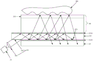
该光学组件包括:光源21、导光器件22和光探测器阵列23。该光学组件的光源21、导光器件22和光探测器阵列23的设置位置可以有多种,比如,光源可以设置在显示面板的一端的下方,也可以设置在显示面板的正下方;光探测器阵列可以设置在显示面板的非显示侧;导光器件可以设置在光探测器阵列和显示面板之间,也可以设置在显示面板的盖板或偏光片的下方。其中,光源设置在显示面板的一端的下方指的是:光源的最外侧的边缘位于显示面板的垂直投影最外侧的边缘外。图1以光源21设置在显示面板00的一端的下方,光探测器阵列23设置在显示面板00的非显示侧,导光器件22设置在光探测器阵列23和显示面板00之间为例进行说明。The optical assembly includes: a
参见图1,光源21用于发出光。Referring to FIG. 1, a
导光器件22用于使光源21发出的光在导光器件22中传播,并将光导向显示面板00的显示侧,其中,导光器件22的面积大于或等于显示面板00的面积。图1示例性示出了导光器件22的面积大于显示面板00的面积。The
光探测器阵列23用于在显示面板00的显示侧存在待识别物体001时,接收该待识别物体反射的光,并根据接收到的该待识别物体反射的光生成用于指示该待识别物体的图像的光信号。该光探测器阵列23包括多个光探测器,比如显示面板每英寸可以对应设置500个光探测器,光探测器阵列23可以覆盖整个显示面板,也即是,光探测器阵列23所在区域的面积等于显示面板的面积。The
示例的,待识别物体可以为指纹或者掌纹。显示面板可以为OLED显示面板。For example, the object to be identified may be a fingerprint or a palm print. The display panel may be an OLED display panel.
图1所示的导光器件能够将光源发出的光在导光器件中传播,并将光导向显示面板的显示侧,导光器件的面积大于或等于显示面板的面积。光探测器阵列在显示面板的显示侧存在待识别物体时,接收该待识别物体反射的光,并根据接收到的该待识别物体反射的光生成用于指示该待识别物体的图像的光信号。之后,处理器根据该光信号形成待识别物体的图像,并将该待识别物体的图像与预先存储于图像库中的图像进行比对,若两者吻合,则识别成功。由于导光器件的面积大于或等于显示面板的面积,所以显示面板的任一位置都能完成纹路识别,实现了全屏识别。同时导光器件的使用还可以降低对光源数量的需求,进而降低了显示组件的成本。另外,将光源设置在显示面板的一端的下方,可以降低光学组件的厚度,降低包括光学组件的显示组件的厚度,进而降低包括显示组件的电子设备的厚度,满足用户对电子设备的使用需求。The light guide device shown in FIG. 1 can propagate the light emitted by the light source in the light guide device and guide the light to the display side of the display panel. The area of the light guide device is greater than or equal to that of the display panel. When there is an object to be identified on the display side of the display panel, the photodetector array receives the light reflected by the object to be identified, and generates an optical signal for indicating the image of the object to be identified according to the received light reflected from the object to be identified . After that, the processor forms an image of the object to be recognized according to the light signal, and compares the image of the object to be recognized with the image stored in the image library in advance. If the two match, the recognition is successful. Since the area of the light guide device is greater than or equal to the area of the display panel, the pattern recognition can be completed at any position of the display panel, realizing full-screen recognition. At the same time, the use of the light guide device can also reduce the demand for the number of light sources, thereby reducing the cost of the display assembly. In addition, arranging the light source below one end of the display panel can reduce the thickness of the optical component, reduce the thickness of the display component including the optical component, and further reduce the thickness of the electronic device including the display component, so as to meet the needs of the user for the use of the electronic device.
该光学组件的识别操作可以用于电子设备的解锁、快捷支付、快速登录软件等应用。以电子设备的解锁应用为例,若识别成功,用户便可以使用电子设备。The identification operation of the optical component can be used for applications such as unlocking of electronic devices, quick payment, and quick login software. Taking the unlocking application of an electronic device as an example, if the identification is successful, the user can use the electronic device.
需要说明的是,关于处理器根据该光信号形成待识别物体的图像,并基于待识别物体的图像对待识别物体纹路进行识别的过程可以参考相关技术,本发明实施例对此不再赘述。It should be noted that, for the process that the processor forms an image of the object to be recognized according to the optical signal, and recognizes the texture of the object to be recognized based on the image of the object to be recognized, reference may be made to the related art, which is not repeated in this embodiment of the present invention.
综上所述,本发明实施例提供的用于物体纹路的光学组件,由于导光器件能够将光源发出的光在导光器件中传播,并将光导向显示面板的显示侧,光探测器阵列在显示面板的显示侧存在待识别物体时,接收该待识别物体反射的光,并根据接收到的该待识别物体反射的光生成用于指示该待识别物体的图像的光信号,由于导光器件的面积大于或等于显示面板的面积,所以显示面板的任一位置都能完成纹路识别,实现了全屏识别,提高了用户体验,提高了纹路识别可靠性。同时导光器件的使用还可以降低对光源数量的需求。另外,将光源设置在显示面板的一端的下方,可以降低电子设备的厚度,满足用户对电子设备的使用需求。To sum up, in the optical assembly for object texture provided by the embodiment of the present invention, since the light guide device can propagate the light emitted by the light source in the light guide device, and guide the light to the display side of the display panel, the photodetector array When there is an object to be identified on the display side of the display panel, the light reflected by the object to be identified is received, and an optical signal indicating the image of the object to be identified is generated according to the received light reflected by the object to be identified. The area of the device is greater than or equal to the area of the display panel, so any position of the display panel can complete the pattern recognition, which realizes the full-screen recognition, improves the user experience, and improves the reliability of the pattern recognition. At the same time, the use of the light guide device can also reduce the demand for the number of light sources. In addition, arranging the light source below one end of the display panel can reduce the thickness of the electronic device and meet the user's requirement for using the electronic device.
图2是本发明实施例提供的另一种用于物体纹路的光学组件和显示面板的结构示意图,该光学组件应用于具有显示面板的电子设备,如图2所示,该光学组件包括:光源21、导光器件22和光探测器阵列23。图2以光源21设置在显示面板00的一端的下方,光探测器阵列23设置在显示面板00的非显示侧,导光器件22设置在光探测器阵列23和显示面板00之间为例进行说明。2 is a schematic structural diagram of another optical component for object texture and a display panel provided by an embodiment of the present invention. The optical component is applied to an electronic device with a display panel. As shown in FIG. 2 , the optical component includes: a
参见图2,光源21用于发出光。Referring to FIG. 2, a
导光器件22用于使光源21发出的光在导光器件22中传播,并将光导向显示面板00的显示侧,其中,导光器件22的面积大于或等于显示面板00的面积。图2示例性示出了导光器件22的面积大于显示面板00的面积。显示面板00包括盖板231。The
光探测器阵列23用于在显示面板00的显示侧存在待识别物体001时,接收该待识别物体反射的光,并根据接收到的该待识别物体反射的光生成用于指示待识别物体的图像的光信号。光探测器阵列23包括多个光探测器,比如显示面板上每英寸设置500个光探测器,光探测器阵列23可以覆盖整个显示面板。待识别物体可以为指纹或者掌纹。The
可选的,光探测器可以为高分辨率的图像传感器,比如,光探测器可以为互补金属氧化物半导体(Complementary Metal Oxide Semiconductor,CMOS)、电荷耦合元件(Charge-coupled Device,CCD)等。Optionally, the photodetector may be a high-resolution image sensor, for example, the photodetector may be a complementary metal oxide semiconductor (Complementary Metal Oxide Semiconductor, CMOS), a charge-coupled device (Charge-coupled Device, CCD), or the like.
参见图2,导光器件22可以包括导光板221和衍射光学器件222,衍射光学器件222设置在导光板221上。Referring to FIG. 2 , the
导光板221的两侧均设置有光折射层2210,光折射层2210的折射率小于导光板221的折射率。衍射光学器件用于将导光板中传播的光导向显示面板的显示侧。Both sides of the
其中,导光板可以由对光具有高透过率的材料制成,示例的,导光板可以由聚碳酸酯(Polycarbonate,PC)、聚甲基丙烯酸甲酯(PolymethylMethacrylate,PMMA)、聚二甲基硅氧烷(polydimethylsiloxane,PDMS)或玻璃材料制成。具有高透过率的导光板便于使待识别物体反射的光通过导光板到达光探测器阵列。The light guide plate may be made of a material with high transmittance to light. For example, the light guide plate may be made of polycarbonate (Polycarbonate, PC), polymethylmethacrylate (PMMA), polydimethylmethacrylate Siloxane (polydimethylsiloxane, PDMS) or glass material. The light guide plate with high transmittance facilitates the light reflected by the object to be recognized to reach the photodetector array through the light guide plate.
导光板221两侧的光折射层2210的折射率小于导光板221的折射率,使得入射至导光板221中的光在导光板221与光折射层2210的界面上可以发生全反射,从而使得光源发出的光在导光器件中传播。假设导光板由折射率为1.585的PC材料制成,光折射层的折射率为1.3,则导光板中光在导光板和光折射层界面上发生全反射的临界角C1=arcsin(1.3/1.585)≈55°,所以,当入射至导光板中的光在导光板和光折射层的界面上的入射角大于55°,比如入射至导光板中的光在导光板和光折射层的界面上的入射角为60°时,光在导光板与光折射层的界面上便可以发生全反射。The refractive index of the light refraction layers 2210 on both sides of the
示例的,光折射层可以由空气或光学胶形成,也即是,如图2所示,导光板221可以分别与显示面板00和光探测器阵列23之间设置有空气层,该空气层即为光折射层。或者,导光板221可以分别与显示面板00和光探测器阵列23之间设置有光学胶层,该光学胶层即为光折射层。本发明实施例对光折射层的形成方式不做限定。Exemplarily, the light refraction layer may be formed of air or optical glue, that is, as shown in FIG. 2 , an air layer may be disposed between the
如图2所示,衍射光学器件222用于将导光板221中传播的光导向显示面板00的显示侧。以便于光探测器阵列23在显示面板00的显示侧存在待识别物体时,接收该待识别物体反射的光,并根据接收到的该待识别物体反射的光生成用于指示该待识别物体的图像的光信号。其中,光的导向方向为图2中u所指示的方向。As shown in FIG. 2 , the diffractive
可选的,显示面板具有矩阵状排布的多个像素,每个像素包括多个子像素,示例的,每个像素可以包括3个子像素,也可以包括5个子像素。当每个像素包括3个子像素时,这3个子像素可以为红色子像素、绿色子像素和蓝色子像素。Optionally, the display panel has a plurality of pixels arranged in a matrix, and each pixel includes a plurality of sub-pixels. For example, each pixel may include 3 sub-pixels, or may include 5 sub-pixels. When each pixel includes 3 sub-pixels, the 3 sub-pixels may be red sub-pixels, green sub-pixels and blue sub-pixels.
图3示出了导光器件的侧视图,导光器件包括导光板221和衍射光学器件222。衍射光学器件222可以包括矩阵状排布的多个衍射光栅021,经过每个衍射光栅021的光从显示面板中的多个子像素之间的空隙穿过,这样一来,避免显示组件显示的画面受到影响。可选的,可以通过调整衍射光栅的位置的方式,或者控制衍射光栅发出的衍射光的出射角的方式,使经过每个衍射光栅的光从显示面板中的多个子像素之间的空隙穿过。FIG. 3 shows a side view of the light guide device, which includes a
为了使读者更加深刻地理解本发明实施例,现对衍射光栅的结构和原理做一简单说明。首先,参见图4-1,图4-1示出了一种衍射光栅021的结构示意图,衍射光栅属于一种光学部件,其包括多个周期性排列的光栅齿0211。衍射光栅的光栅周期d指的是任意相邻的两个光栅齿的中心的距离,光栅周期的量级与光波长的量级为同一量级。衍射光栅的每个光栅齿0211的高度H的量级与光波长的量级也为同一量级。衍射光栅的光栅周期和每个光栅齿的高度可以根据实际需求来设置,示例的,衍射光栅的光栅周期可以为300纳米,每个光栅齿的高度可以为300纳米。In order to enable readers to understand the embodiments of the present invention more deeply, the structure and principle of the diffraction grating will now be briefly described. First, referring to FIG. 4-1, FIG. 4-1 shows a schematic structural diagram of a
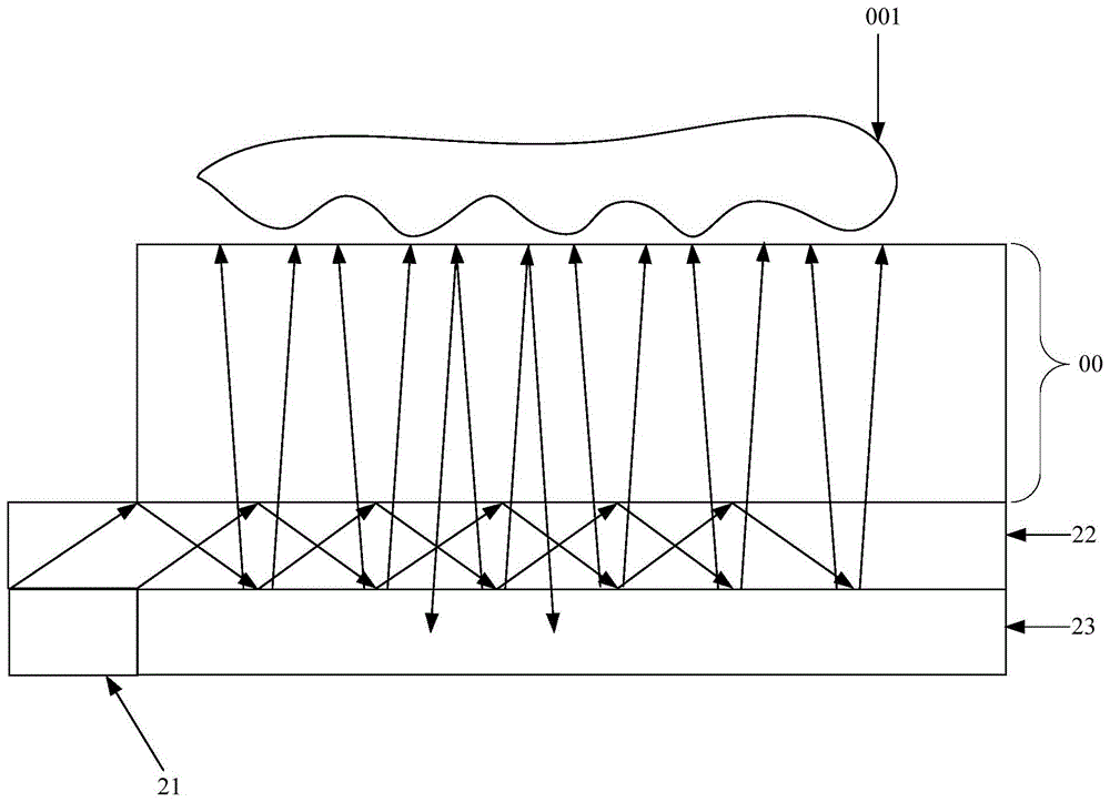
图4-2示出了入射至图4-1所示的衍射光栅的光的传播路径示意图,图4-2中,R1和R2均为入射至衍射光栅的光,

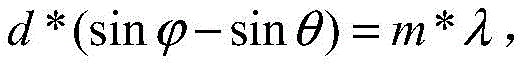


如图2所示,当入射至导光板221中的光到达衍射光学器件222时,入射角为


在另一种可实现方式中,为了提高光源的光利用率,进而提高纹路识别准确度,用于物体纹路的光学组件还可以包括光路准直器,该光路准直器用于对光源发出的光进行汇聚并耦合至导光器件内。示例的,该光学组件可以如图5-1所示,该光学组件包括:光源21、导光器件22和光探测器阵列23。图5-1同样以光源21设置在显示面板00的一端的下方,光探测器阵列23设置在显示面板00的非显示侧,导光器件22设置在光探测器阵列23和显示面板00之间为例进行说明。In another achievable manner, in order to improve the light utilization rate of the light source and further improve the accuracy of texture identification, the optical component used for the texture of the object may further include an optical path collimator, and the optical path collimator is used for the light emitted by the light source. Condensed and coupled into the light guide. For example, the optical assembly may be as shown in FIG. 5-1 . The optical assembly includes: a
其中,光源21用于发出光。Among them, the
导光器件22用于使光源发出的光在导光器件22中传播,并将光导向显示面板00的显示侧,其中,导光器件22的面积大于或等于显示面板00的面积。图5-1示例性示出了导光器件22的面积大于显示面板00的面积。The
光探测器阵列23用于在显示面板00的显示侧存在待识别物体001时,接收该待识别物体反射的光,并根据接收到的该待识别物体反射的光生成用于指示该待识别物体的图像的光信号。The
导光器件22可以包括导光板221和衍射光学器件222,衍射光学器件222设置在导光板221上。衍射光学器件用于将导光板中传播的光导向显示面板的显示侧。衍射光学器件222可以包括矩阵状排布的多个衍射光栅021。导光板221的两侧均设置有光折射层2210,光折射层2210的折射率小于导光板221的折射率。The
该光学组件还包括:光路准直器24,光路准直器24设置在光源21和导光器件22之间。光路准直器24用于对光源21发出的光进行汇聚并耦合至导光器件22内。The optical assembly further includes: an
光源发出的光通过光路准直器被耦合至导光器件内,使得导光器件能够使光源发出的更多的光在导光器件中传播,并将光导向显示面板的显示侧,从而使光探测器阵列接收到的待识别物体反射的光的强度更高,提高了光源的光利用率,进而提高了纹路识别准确度。The light emitted by the light source is coupled into the light guide device through the optical path collimator, so that the light guide device can make more light emitted by the light source propagate in the light guide device, and guide the light to the display side of the display panel, so that the light The intensity of the light reflected by the object to be recognized received by the detector array is higher, the light utilization rate of the light source is improved, and the accuracy of pattern recognition is further improved.
可选的,如图5-1所示,光路准直器24可以包括汇聚透镜241和耦合光栅242。其中,光源21设置在汇聚透镜241的焦距位置,耦合光栅242设置在汇聚透镜241和导光器件22之间。Optionally, as shown in FIG. 5-1 , the optical path collimator 24 may include a converging
汇聚透镜241用于将光源21发出的光汇聚为准直光束。The converging
耦合光栅242用于将准直光束耦合至导光器件22内。The
光源发出的光通过汇聚透镜和耦合光栅被耦合至导光器件内,使得导光器件能够将光源发出的更多的光在导光器件中传播,并将光导向显示面板的显示侧。The light emitted by the light source is coupled into the light guide device through the converging lens and the coupling grating, so that the light guide device can transmit more light emitted by the light source in the light guide device and guide the light to the display side of the display panel.
示例的,如图5-1所示,可以采用纳米压印工艺在导光板远离显示面板的一侧形成耦合光栅。另外,在实际应用中,还可以根据汇聚透镜的大小来确定耦合光栅在导光板上需要占用的区域面积大小。Exemplarily, as shown in FIG. 5-1 , a nano-imprinting process may be used to form a coupling grating on the side of the light guide plate away from the display panel. In addition, in practical applications, the size of the area that the coupling grating needs to occupy on the light guide plate can also be determined according to the size of the converging lens.
假设显示面板的显示侧的待识别物体为指纹,那么图5-1所示的光学组件的工作过程可以为:光源21发出光,汇聚透镜241将光源21发出的光汇聚为准直光束,耦合光栅242将准直光束耦合至导光器件22的导光板221内。入射至导光板221中的光在导光板221与光折射层2210的界面上发生全反射,发生全反射的光经过衍射光栅021产生垂直于衍射光栅而传播的正一级衍射光(传播方向为图5-1中u所指示的方向)。正一级衍射光经过显示面板到达显示面板00的盖板231与指纹001的界面。而指纹是人体与生俱来、独一无二并可与他人相区别的不变特征,指纹是由指端皮肤表面上一系列的指纹脊和指纹谷组成的,这些指纹脊和指纹谷的组成细节通常包括指纹脊的分叉、指纹脊的末端、拱形、帐篷式的拱形、左旋、右旋、螺旋或双旋等细节,这些细节决定了指纹图像的唯一性。如图5-2所示,当手指接触盖板231表面时,指纹脊与盖板231接触,指纹谷与盖板231之间存在空气。由于与显示面板00的盖板231表面接触的指纹脊的折射率大于盖板231与指纹谷之间的空气的折射率,所以,指纹脊反射的光的强度与指纹谷反射的光的强度不同,这样一来,指纹001反射的光的强度就携带了指纹的区域信息,该区域信息用于指示指纹脊或指纹谷。最终,如图5-1所示,光探测器阵列23根据指纹脊反射的光生成的光信号和根据指纹谷反射的光生成的光信号不同,这样一来,处理器便可以基于光探测器阵列23生成的两种光信号形成指纹图像。Assuming that the object to be recognized on the display side of the display panel is a fingerprint, the working process of the optical assembly shown in Figure 5-1 can be as follows: the
图5-1中其他标记含义可以参考图2。Refer to Figure 2 for the meanings of other symbols in Figure 5-1.
图5-3示出了图5-1所示的光学组件的俯视图,如图5-3所示,光路准直器24设置在光源21和导光器件的导光板221之间。光路准直器24包括汇聚透镜241和耦合光栅242,光源21设置在汇聚透镜241的焦距位置。衍射光学器件包括矩阵状排布的多个衍射光栅021。Fig. 5-3 shows a top view of the optical assembly shown in Fig. 5-1. As shown in Fig. 5-3, the
可选的,如图5-3所示,光源21可以包括多个子光源211,汇聚透镜241可以包括多个子透镜2411,多个子光源与多个子透镜一一对应。示例的,子透镜可以为微透镜、柱透镜或准直器,准直器包括快轴准直器和慢轴准直器。本发明实施例对子透镜的类型不做限定。Optionally, as shown in FIG. 5-3 , the
此外,光源也可以为一激光器,汇聚透镜可以为一微透镜或一柱透镜,激光器设置在微透镜或柱透镜的焦距位置。In addition, the light source can also be a laser, the converging lens can be a microlens or a cylindrical lens, and the laser is arranged at the focal length of the microlens or the cylindrical lens.
可选的,如图5-3所示,多个衍射光栅021为矩阵状等间距排布,且排布的间距D可以为20微米~400微米。在实际应用中,衍射光学器件包括的多个衍射光栅可以与分辨率为600每英寸像素(Pixel Per Inch,PPI)的显示面板配合使用。显示面板的分辨率越高,衍射光学器件包括的衍射光栅排布的间距越小。Optionally, as shown in FIG. 5-3 , the plurality of
示例的,如图6所示,每个衍射光栅021的长度a可以为5微米~30微米,宽度b可以为5微米~30微米。For example, as shown in FIG. 6 , the length a of each
在又一种可实现方式中,为了简化图5-1所示的光学组件的结构,可以将用于物体纹路的光学组件的光源设置在导光器件的侧壁上,在这种情况下,光学组件无需设置光路准直器。示例的,该光学组件可以如图7所示,该光学组件包括:光源21、导光器件22和光探测器阵列23。图7以光探测器阵列23设置在显示面板00的非显示侧,导光器件22设置在光探测器阵列23和显示面板00之间为例进行说明。参见图7,由于光源21设置在导光器件22的侧壁上,光源21和导光器件22位于同一层,这样,光学组件可以不用设置光路准直器。In yet another implementation manner, in order to simplify the structure of the optical assembly shown in FIG. 5-1, the light source of the optical assembly used for the texture of the object can be arranged on the side wall of the light guide device. In this case, Optical components do not need to set optical path collimators. Exemplarily, the optical assembly may be as shown in FIG. 7 , and the optical assembly includes: a
图7中其他标记的含义可以参考图2和图5-1。For the meanings of other marks in Fig. 7, please refer to Fig. 2 and Fig. 5-1.
需要补充说明的是,本发明实施例中的用于物体纹路的光学组件,第一方面,衍射光学器件发出的衍射光的出射角(即入射至衍射光栅的光在衍射光栅上发生衍射时的衍射角)可以小于预设角度值,使衍射光在显示面板的盖板和空气的界面不发生全反射。第二方面,衍射光学器件发出的衍射光的出射角可以大于或等于预设角度值,使衍射光在显示面板的盖板和空气的界面发生全反射,当衍射光在显示面板的盖板和空气的界面发生全反射时,相较于第一方面,能够提高待识别物体的图像的清晰度,进而提高纹路识别的准确度。It should be supplemented that, in the first aspect of the optical component used for the texture of the object in the embodiment of the present invention, the exit angle of the diffracted light emitted by the diffractive optical device (that is, when the light incident on the diffraction grating is diffracted on the diffraction grating) Diffraction angle) can be smaller than the preset angle value, so that the diffracted light will not be totally reflected at the interface between the cover plate of the display panel and the air. In the second aspect, the exit angle of the diffracted light emitted by the diffractive optical device can be greater than or equal to the preset angle value, so that the diffracted light is totally reflected at the interface between the cover plate and the air of the display panel. When total reflection occurs at the interface of the air, compared with the first aspect, the clarity of the image of the object to be recognized can be improved, thereby improving the accuracy of texture recognition.
其中,第一方面和第二方面所述的预设角度值θ1满足:θ1=arcsin(n2*sinθ2/n1),n1为导光板的折射率,n2为盖板的折射率,θ2为衍射光在盖板和空气的界面上的入射角。该入射角θ2满足:θ2>arcsin(n3/n2),其中,n3为空气的折射率。Wherein, the preset angle value θ1 described in the first aspect and the second aspect satisfies: θ1=arcsin(n2*sinθ2/n1), n1 is the refractive index of the light guide plate, n2 is the refractive index of the cover plate, and θ2 is the diffracted light The angle of incidence at the interface of the cover plate and air. The incident angle θ2 satisfies: θ2>arcsin(n3/n2), where n3 is the refractive index of air.
假设待识别物体为指纹,为了进一步提高指纹图像的清晰度,可以增大第二界面反射的光的强度与第一界面反射的光的强度的差值。其中,第二界面指的是显示面板的盖板与空气(即指纹谷与盖板之间存在的空气)的界面,第一界面指的是盖板与指纹脊的界面。为了增大第二界面反射的光的强度与第一界面反射的光的强度的差值,可以使衍射光学器件发出的衍射光的出射角大于或等于预设角度值,使衍射光在第二界面即显示面板的盖板和空气的界面发生全反射。Assuming that the object to be recognized is a fingerprint, in order to further improve the clarity of the fingerprint image, the difference between the intensity of the light reflected by the second interface and the intensity of the light reflected by the first interface can be increased. The second interface refers to the interface between the cover plate of the display panel and the air (ie, the air existing between the fingerprint valley and the cover plate), and the first interface refers to the interface between the cover plate and the fingerprint ridge. In order to increase the difference between the intensity of the light reflected by the second interface and the intensity of the light reflected by the first interface, the exit angle of the diffracted light emitted by the diffractive optical device can be greater than or equal to the preset angle value, so that the diffracted light is at the second interface. The interface, that is, the interface between the cover plate of the display panel and the air, undergoes total reflection.
示例的,可以通过设置衍射光栅的光栅周期d和调节入射至衍射光栅的光的入射角
相关技术中,假设光从第一介质射向第一介质与第二介质的界面,第一介质的折射率为m1,第二介质的折射率为m2,光在该界面上的入射角为ζ1,折射角为ζ2,那么则有:m1*sinζ1=m2*sinζ2,该公式称为折射定律公式。将该折射定律公式对应于图8-1,则有:n1*sinθ1=n4*sinω=n2*sinθ2,所以有:θ1=arcsin(n2*sinθ2/n1)。示例的,盖板231的折射率n2为1.51,导光板221的折射率n1为1.585,盖板231中射向盖板231和空气的界面上的光的入射角θ2为50°,那么预设角度值θ1=arcsin(n2*sinθ2/n1)=46.9,也即是,衍射光学器件发出的衍射光的出射角对应的预设角度为46.9°。当衍射光学器件发出的衍射光的出射角大于或等于46.9°时,盖板231中射向盖板231和空气的界面上的光便可以发生全反射。假设入射至衍射光栅的光的入射角


示例的,图8-2示出了衍射光在显示面板的盖板和空气的界面发生全反射时,光学组件的工作过程示意图,图8-2以光源21设置在显示面板00的一端的下方,光探测器阵列23设置在显示面板00的非显示侧,导光器件22设置在光探测器阵列23和显示面板00之间为例进行说明。假设待识别物体为指纹,该光学组件的工作过程可以为:光源21发出光,汇聚透镜241将光源21发出的光汇聚为准直光束,耦合光栅242将准直光束耦合至导光器件的导光板221内。入射至导光板221中的光在导光板221与光折射层2210的界面上发生全反射,发生全反射的光经过衍射光栅021产生向显示面板的显示侧传播的正一级衍射光,正一级衍射光的出射角大于预设角度值。如图8-3所示,正一级衍射光分为两部分:第一部分正一级衍射光和第二部分正一级衍射光。第一部分正一级衍射光经过显示面板00到达显示面板00的盖板231和空气(即指纹谷与盖板之间存在的空气)的界面,第一部分正一级衍射光的出射角大于预设角度值,所以第一部分正一级衍射光在盖板231和空气的界面上发生全反射。假设到达盖板231和空气的界面上的第一部分正一级衍射光的强度为q1,那么由盖板231和空气的界面反射的光的强度也为q1。第二部分正一级衍射光到达盖板231和指纹脊的界面,由于盖板231的折射率与指纹脊的折射率相接近,所以盖板231和指纹脊不满足全反射条件,该第二部分正一级衍射光在盖板231和指纹脊的界面上不会发生全反射,第二部分正一级衍射光中的大部分光会射向并泄漏至指纹脊中。假设到达盖板231和指纹脊的界面上的第二部分正一级衍射光的强度为q2,如果用q3来表示由盖板231和指纹脊的界面反射的光的强度,则有:q2>q3>0。8-2 shows a schematic diagram of the working process of the optical assembly when the diffracted light is totally reflected at the interface of the cover plate of the display panel and the air. In FIG. 8-2, the
由于第二界面(即盖板与空气的界面)反射的光的强度与第一界面(即盖板与指纹脊的界面)反射的光的强度的差值更大,所以光探测器阵列根据第二界面反射的光生成的光信号和根据第一界面反射的光生成的光信号的差异更大,从而使处理器能够基于光探测器阵列生成的两种差异更大的光信号形成清晰度更高的指纹图像。图8-2中的其他标记可以参考图5-1。Since the difference between the intensity of the light reflected by the second interface (ie, the interface between the cover plate and the air) and the intensity of the light reflected by the first interface (ie, the interface between the cover plate and the fingerprint ridge) is larger, the photodetector array is based on the first interface. The difference between the optical signal generated by the light reflected by the second interface and the optical signal generated according to the light reflected by the first interface is greater, so that the processor can form a more clear optical signal based on the two more different optical signals generated by the photodetector array. High fingerprint image. Other labels in Figure 8-2 can refer to Figure 5-1.
所以,在第二方面中,衍射光学器件发出的衍射光的出射角大于或等于预设角度值,可以使衍射光在显示面板的盖板和空气的界面发生全反射,衍射光的反射率为100%,盖板与空气的界面反射的光的强度更大,这样一来,光探测器阵列根据盖板与空气的界面反射的光生成的光信号,和根据盖板与待识别物体的界面反射的光生成的光信号的差异更大,从而使处理器能够基于光探测器阵列生成的两种差异更大的光信号形成清晰度更高的待识别物体的图像。Therefore, in the second aspect, the exit angle of the diffracted light emitted by the diffractive optical device is greater than or equal to the preset angle value, so that the diffracted light can be totally reflected at the interface between the cover plate of the display panel and the air, and the reflectance of the diffracted light is 100%, the intensity of the light reflected by the interface between the cover plate and the air is greater, so that the light signal generated by the photodetector array according to the light reflected from the interface between the cover plate and the air, and the light signal generated by the interface between the cover plate and the object to be recognized The difference between the optical signals generated by the reflected light is greater, so that the processor can form a higher definition image of the object to be identified based on the two more different optical signals generated by the photodetector array.
进一步的,基于该第二方面,可以通过控制衍射光栅发出的衍射光的出射角的方式,使经过衍射光栅的光从显示面板中的多个子像素之间的空隙穿过,避免显示组件显示的画面受到影响。Further, based on the second aspect, the light passing through the diffraction grating can pass through the gaps between the plurality of sub-pixels in the display panel by controlling the exit angle of the diffracted light emitted by the diffraction grating, so as to prevent the display component from displaying the light. The screen is affected.
本发明实施例提供的用于物体纹路的光学组件可以应用于具有显示面板的电子设备,示例的,该显示面板可以为OLED显示面板。图8-4示出了相关技术中OLED显示面板的结构示意图,该显示面板包括:阵列基板831、用于对阵列基板831起覆盖和保护作用的封装层832、依次设置在封装层832远离阵列基板831一侧的偏光片833、光学透明胶834和盖板231。The optical assembly for object texture provided in the embodiment of the present invention may be applied to an electronic device having a display panel, for example, the display panel may be an OLED display panel. 8-4 shows a schematic structural diagram of an OLED display panel in the related art. The display panel includes: an
可选的,用于物体纹路的光学组件的导光器件可以设置在图8-4所示的显示面板的盖板231的下方,即盖板与光学透明胶之间,或者设置在偏光片833的下方,即偏光片与封装层之间。图9-1示例性示出了导光器件22设置在显示面板00的盖板231的下方时该光学组件的结构示意图,该光学组件包括光源21、导光器件和光探测器阵列23。Optionally, the light guide device of the optical component used for the texture of the object can be arranged under the
光探测器阵列23可以设置在显示面板00的非显示侧,光源21可以设置在显示面板00的一端,也即是,光源21与显示面板00位于同一层。The
导光器件可以包括导光板221和衍射光学器件,衍射光学器件设置在导光板221上。衍射光学器件可以包括矩阵状排布的多个衍射光栅021,经过每个衍射光栅的光从显示面板中的多个子像素之间的空隙穿过。导光板221的两侧均设置有光折射层2210,光折射层2210的折射率小于导光板221的折射率。The light guide device may include a
示例的,为了提高待识别物体的图像的清晰度,衍射光学器件发出的衍射光的出射角可以大于或等于预设角度值,使衍射光在显示面板的盖板和空气的界面发生全反射。For example, in order to improve the clarity of the image of the object to be recognized, the exit angle of the diffracted light emitted by the diffractive optical device may be greater than or equal to a preset angle value, so that the diffracted light is totally reflected at the interface between the cover plate of the display panel and the air.
进一步的,参考图5-1,该显示组件还可以包括:光路准直器,光路准直器设置在光源和导光器件之间。光路准直器用于对光源发出的光进行汇聚并耦合至导光器件内。光路准直器可以包括汇聚透镜和耦合光栅。光源设置在汇聚透镜的焦距位置,耦合光栅设置在汇聚透镜和导光器件之间。汇聚透镜用于将光源发出的光线汇聚为准直光束,耦合光栅用于将准直光束耦合至导光器件内。Further, referring to FIG. 5-1 , the display assembly may further include: an optical path collimator, and the optical path collimator is disposed between the light source and the light guide device. The optical path collimator is used to collect the light emitted by the light source and couple it into the light guide device. The optical path collimator may include a converging lens and a coupling grating. The light source is arranged at the focal length of the converging lens, and the coupling grating is arranged between the converging lens and the light guide device. The converging lens is used for converging the light emitted by the light source into a collimated light beam, and the coupling grating is used for coupling the collimated light beam into the light guide device.
另外,光源21也可以如图7所示,设置在导光板221的侧壁上,以简化光学组件的结构,省去光路准直器的设置过程。In addition, as shown in FIG. 7 , the
图9-1中的其他标号可以参考图2和图5-1。Other reference numbers in Figure 9-1 may refer to Figure 2 and Figure 5-1.
本发明实施例提供的用于物体纹路的光学组件,导光器件将光源发出的光在导光器件中传播,并将光导向显示面板的显示侧,导光器件的面积大于或等于显示面板的面积。光探测器阵列在显示面板的显示侧存在待识别物体时,接收该待识别物体反射的光,并根据接收到的该待识别物体反射的光生成用于指示该待识别物体的图像的光信号,实现了全屏识别。同时导光器件的使用还可以降低对光源数量的需求,进而降低了显示组件的成本。另外,将光源设置在显示面板的一端的下方,可以降低光学组件的厚度,进而降低电子设备的厚度,满足用户对电子设备的使用需求。进一步的,通过光路准直器使得光探测器阵列接收到的待识别物体反射的光的强度更高,提高了光源的光利用率,提高了纹路识别准确度。In the optical assembly for object texture provided by the embodiment of the present invention, the light guide device propagates the light emitted by the light source in the light guide device, and guides the light to the display side of the display panel, and the area of the light guide device is greater than or equal to the area of the display panel. area. When there is an object to be identified on the display side of the display panel, the photodetector array receives the light reflected by the object to be identified, and generates an optical signal for indicating the image of the object to be identified according to the received light reflected from the object to be identified , to achieve full-screen recognition. At the same time, the use of the light guide device can also reduce the demand for the number of light sources, thereby reducing the cost of the display assembly. In addition, arranging the light source below one end of the display panel can reduce the thickness of the optical component, thereby reducing the thickness of the electronic device, so as to meet the needs of the user for the use of the electronic device. Further, through the optical path collimator, the intensity of the light reflected by the object to be identified received by the photodetector array is higher, the light utilization rate of the light source is improved, and the texture identification accuracy is improved.
需要补充说明的是,对于移动终端来说,全屏指纹识别技术是未来指纹识别技术的发展趋势,全屏指纹识别技术的目标是在移动终端屏幕的任意区域完成指纹检测和识别。全屏指纹识别技术可以提高移动终端的屏占比(屏占比指的是移动终端屏幕的面积与移动终端前面板的面积的比值),且能够为用户提供较好的指纹解锁体验。目前,全屏指纹识别技术面临的三大主要问题是:1、在指纹传感器与显示组件相集成的情况下,移动终端屏幕不能太厚;2、指纹反射的光通过移动终端屏幕复杂的层叠结构后需要形成较清晰的指纹图像;3、如图9-2所示,将指纹识别区域设置在移动终端屏幕上时,移动终端屏幕不能太厚。而本发明实施例提供的用于物体纹路的光学组件,针对于未来的全屏指纹识别技术,能够使得移动终端屏幕的厚度较小,能够得到满足指纹识别需求的较清晰的指纹图像,所以该光学组件可以很好地应用于未来的全屏指纹识别技术中,适应技术发展趋势。It should be added that for mobile terminals, full-screen fingerprint recognition technology is the development trend of fingerprint recognition technology in the future. The goal of full-screen fingerprint recognition technology is to complete fingerprint detection and recognition in any area of the mobile terminal screen. The full-screen fingerprint recognition technology can increase the screen ratio of the mobile terminal (the screen ratio refers to the ratio of the area of the mobile terminal screen to the area of the front panel of the mobile terminal), and can provide users with a better fingerprint unlocking experience. At present, the three main problems faced by full-screen fingerprint recognition technology are: 1. When the fingerprint sensor is integrated with the display component, the screen of the mobile terminal cannot be too thick; 2. After the light reflected by the fingerprint passes through the complex laminated structure of the screen of the mobile terminal A clearer fingerprint image needs to be formed; 3. As shown in Figure 9-2, when the fingerprint identification area is set on the screen of the mobile terminal, the screen of the mobile terminal should not be too thick. However, the optical component for object texture provided by the embodiment of the present invention is aimed at the future full-screen fingerprint recognition technology, which can make the thickness of the screen of the mobile terminal smaller, and can obtain a clearer fingerprint image that meets the needs of fingerprint recognition. The components can be well applied to the future full-screen fingerprint recognition technology to adapt to the technological development trend.
综上所述,本发明实施例提供的用于物体纹路的光学组件,由于导光器件能够将光源发出的光在导光器件中传播,并将光导向显示面板的显示侧,光探测器阵列在显示面板的显示侧存在待识别物体时,接收该待识别物体反射的光,并根据接收到的该待识别物体反射的光生成用于指示该待识别物体的图像的光信号,导光器件的面积大于或等于显示面板的面积,所以显示面板的任一位置都能完成纹路识别,实现了全屏识别,提高了用户体验,提高了纹路识别可靠性。同时导光器件的使用还可以降低对光源数量的需求,进而降低了显示组件的成本。另外,将光源设置在显示面板的一端的下方,可以降低电子设备的厚度,满足用户对电子设备的使用需求,进一步的,还提高了光源的光利用率,提高了纹路识别的准确度。To sum up, in the optical assembly for object texture provided by the embodiment of the present invention, since the light guide device can propagate the light emitted by the light source in the light guide device, and guide the light to the display side of the display panel, the photodetector array When there is an object to be identified on the display side of the display panel, the light guide device receives the light reflected by the object to be identified, and generates an optical signal for indicating the image of the object to be identified according to the received light reflected from the object to be identified. The area of the display panel is greater than or equal to the area of the display panel, so any position of the display panel can complete the pattern recognition, realize the full screen recognition, improve the user experience, and improve the reliability of the pattern recognition. At the same time, the use of the light guide device can also reduce the demand for the number of light sources, thereby reducing the cost of the display assembly. In addition, arranging the light source below one end of the display panel can reduce the thickness of the electronic device, meet the user's demand for the use of the electronic device, further improve the light utilization rate of the light source, and improve the accuracy of pattern recognition.
本发明实施例还提供了一种显示组件,该显示组件可以如图1、图2、图5-1、图7、图8-2或图9-1所示,包括显示面板和对应图中所示的光学组件。其中,显示面板可以为OLED显示面板。An embodiment of the present invention further provides a display assembly, which may be shown in FIG. 1 , FIG. 2 , FIG. 5-1 , FIG. 7 , FIG. 8-2 or FIG. 9-1 , including a display panel and corresponding diagrams Optical components shown. Wherein, the display panel may be an OLED display panel.
本发明实施例还提供了一种电子设备,该电子设备可以包括图1、图2、图5-1、图7、图8-2或图9-1所示的显示组件和处理器(如CPU),该处理器用于根据显示组件的光学组件得到的光信号形成待识别物体的图像。An embodiment of the present invention further provides an electronic device, which may include the display component and the processor shown in FIG. 1, FIG. 2, FIG. 5-1, FIG. 7, FIG. 8-2 or FIG. 9-1 (eg CPU), the processor is configured to form an image of the object to be identified according to the light signal obtained by the optical component of the display component.
示例的,该电子设备可以为智能手机、平板电脑、电视机、显示器、笔记本电脑、可穿戴设备、数码相框、导航仪等具有显示功能的产品或部件。For example, the electronic device may be a product or component with a display function, such as a smart phone, a tablet computer, a television, a monitor, a notebook computer, a wearable device, a digital photo frame, a navigator, and the like.
综上所述,本发明实施例提供的电子设备,由于该电子设备的显示组件包括用于物体纹路的光学组件,该光学组件的导光器件能够将光源发出的光在导光器件中传播,并将光导向显示面板的显示侧,光探测器阵列在显示面板的显示侧存在待识别物体时,接收该待识别物体反射的光,并根据接收到的该待识别物体反射的光生成用于指示该待识别物体的图像的光信号,且导光器件的面积大于或等于显示面板的面积,所以显示面板的任一位置都能完成纹路识别,实现了全屏识别,提高了用户体验,提高了纹路识别可靠性。同时导光器件的使用还可以降低对光源数量的需求,进而降低了电子设备的成本。另外,将光源设置在显示面板的一端的下方,可以降低电子设备的厚度,满足用户对电子设备的使用需求,进一步的,还提高了光源的光利用率,提高了纹路识别准确度。To sum up, in the electronic device provided by the embodiments of the present invention, since the display component of the electronic device includes an optical component for object texture, the light guide device of the optical component can propagate the light emitted by the light source in the light guide device, The light is guided to the display side of the display panel, and when there is an object to be identified on the display side of the display panel, the photodetector array receives the light reflected by the object to be identified, and generates light for the object to be identified according to the received light reflected by the object to be identified. The light signal indicating the image of the object to be recognized, and the area of the light guide device is greater than or equal to the area of the display panel, so any position of the display panel can complete the pattern recognition, realize the full-screen recognition, improve the user experience, and improve the Texture recognition reliability. At the same time, the use of the light guide device can also reduce the demand for the number of light sources, thereby reducing the cost of electronic equipment. In addition, arranging the light source below one end of the display panel can reduce the thickness of the electronic device, meet the user's demand for the use of the electronic device, further improve the light utilization rate of the light source, and improve the accuracy of pattern recognition.
本发明实施例还提供了一种用于物体纹路的光学组件的制造方法,该方法可包括:Embodiments of the present invention also provide a method for manufacturing an optical component for object texture, the method may include:
分别形成光源、导光器件和光探测器阵列。A light source, a light guide device and a photodetector array are formed respectively.
其中,光源用于发出光。导光器件用于使光源发出的光在导光器件中传播,并将光导向显示面板的显示侧,导光器件的面积大于或等于显示面板的面积。光探测器阵列用于在显示面板的显示侧存在待识别物体时,接收该待识别物体反射的光,并根据接收到的该待识别物体反射的光生成用于指示该待识别物体的图像的光信号。Among them, the light source is used to emit light. The light guide device is used to make the light emitted by the light source propagate in the light guide device and guide the light to the display side of the display panel, and the area of the light guide device is greater than or equal to that of the display panel. The photodetector array is used to receive the light reflected by the object to be identified when there is an object to be identified on the display side of the display panel, and to generate an image indicating the object to be identified according to the received light reflected from the object to be identified. light signal.
以图1为例,可以分别形成光源21、导光器件22和光探测器阵列23,然后,将形成的导光器件22和光探测器阵列23依次形成在显示面板的非显示侧,将形成的光源21形成在显示面板的一端的下方。Taking FIG. 1 as an example, the
可选的,如图2所示,导光器件22可以包括导光板221和衍射光学器件222,相应的,如图10-1所示,形成导光器件,包括:Optionally, as shown in FIG. 2, the
步骤1001、在导光板上形成衍射光学器件。
如图3所示,在导光板221上形成衍射光学器件222。As shown in FIG. 3 , the diffractive
可选的,显示面板具有矩阵状排布的多个像素,每个像素包括多个子像素,衍射光学器件可以包括矩阵状排布的多个衍射光栅,相应的,如图3和图10-2所示,步骤1001可以包括:Optionally, the display panel has a plurality of pixels arranged in a matrix, each pixel includes a plurality of sub-pixels, and the diffractive optical device may include a plurality of diffraction gratings arranged in a matrix, correspondingly, as shown in Figure 3 and Figure 10-2 As shown,
在导光板221上形成多个衍射光栅021,经过每个衍射光栅的光从显示面板中的多个子像素之间的空隙穿过,避免显示组件显示的画面受到影响。可选的,可以通过调整衍射光栅的位置的方式,或者控制衍射光栅发出的衍射光的出射角的方式,使经过每个衍射光栅的光从显示面板中的多个子像素之间的空隙穿过。A plurality of
示例的,在导光板上形成多个衍射光栅,可以包括:通过纳米压印工艺在导光板上形成多个衍射光栅。For example, forming a plurality of diffraction gratings on the light guide plate may include: forming a plurality of diffraction gratings on the light guide plate through a nano-imprinting process.
示例的,多个衍射光栅为矩阵状等间距排布,排布的间距可以为20微米~400微米。每个衍射光栅021的长度可以为5微米~30微米,宽度可以为5微米~30微米。Exemplarily, the plurality of diffraction gratings are arranged in a matrix shape at equal intervals, and the arranged interval may be 20 micrometers to 400 micrometers. The length of each
步骤1002、在形成有衍射光学器件的导光板的两侧形成光折射层。
如图10-2所示,在形成有衍射光学器件222的导光板221的两侧形成光折射层2210。As shown in FIG. 10-2 , light refraction layers 2210 are formed on both sides of the
光折射层的折射率小于导光板的折射率,衍射光学器件用于将导光板中传播的光导向显示面板的显示侧。The refractive index of the light refraction layer is smaller than that of the light guide plate, and the diffractive optical device is used to guide the light propagating in the light guide plate to the display side of the display panel.
该光学组件包括的光源、导光器件和光探测器阵列的形成位置可以有多种,比如参考图2、图5-1、图7、图8-2或图9-1,形成光探测器阵列可以包括:在显示面板00的非显示侧形成光探测器阵列23。示例的,可以在显示面板的非显示侧每英寸对应形成500个光探测器。光探测器阵列覆盖整个显示面板。The light source, the light guide device and the photodetector array included in the optical assembly can be formed in various positions. For example, referring to FIG. 2 , FIG. 5-1 , FIG. 7 , FIG. 8-2 or FIG. 9-1 , the photodetector array is formed. It may include: forming the
比如参考图1、图2、图5-1、图7或图8-2,形成导光器件可以包括:For example, referring to FIG. 1 , FIG. 2 , FIG. 5-1 , FIG. 7 or FIG. 8-2 , forming the light guide device may include:
在显示面板00靠近光探测器阵列23的一侧形成导光器件22,导光器件22位于光探测器阵列23和显示面板00之间。A
参见图8-4,显示面板包括盖板231和偏光片833,所以也可以参考图9-1,在显示面板00远离光探测器阵列23的一侧形成导光器件22,导光器件22位于显示面板00的盖板231的下方。Referring to FIG. 8-4, the display panel includes a
图9-1中的导光器件22也可以位于显示面板的偏光片的下方。The
比如参考图1、图2、图5-1或图8-2,形成光源可以包括:在显示面板00的一端的下方形成光源21,使得光源的最外侧的边缘位于显示面板的垂直投影最外侧的边缘外。将光源形成在显示面板的一端的下方,可以降低光学组件的厚度,降低包括光学组件的显示组件的厚度,进而降低包括显示组件的电子设备的厚度,满足用户对电子设备的使用需求。For example, referring to FIG. 1 , FIG. 2 , FIG. 5-1 or FIG. 8-2 , forming the light source may include: forming the
示例的,也可以参考图7,在导光器22的侧壁上形成光源21,光源21和导光器件22位于同一层,简化了图5-1所示的光学组件的制造过程。7, the
示例的,也可以参考图9-1,在显示面板00的一端形成光源21,光源21与显示面板00位于同一层。9-1, a
进一步的,如图5-1所示,光学组件还可以包括:光路准直器24,相应的,在显示面板的一端的下方形成光源之后,该方法还可以包括:Further, as shown in FIG. 5-1, the optical assembly may further include: an
在光源21和导光器件22之间形成光路准直器24,该光路准直器24用于对光源21发出的光进行汇聚并耦合至导光器件22内。光源发出的光通过光路准直器被耦合至导光器件内,使得导光器件能够使光源发出的更多的光在导光器件中传播,并将光导向显示面板的显示侧,从而使光探测器阵列接收到的待识别物体反射的光的强度更高,提高了光源的光利用率,进而提高了纹路识别准确度。An
可选的,如图5-1所示,光路准直器24包括汇聚透镜241和耦合光栅242,相应的,在光源和导光器件之间形成光路准直器,包括:Optionally, as shown in FIG. 5-1, the
在光源21和导光器件22之间形成汇聚透镜241,使光源21位于汇聚透镜241的焦距位置。A condensing
在汇聚透镜241和导光器件22之间形成耦合光栅242。A coupling grating 242 is formed between the condensing
其中,汇聚透镜241用于将光源21发出的光汇聚为准直光束,耦合光栅242用于将准直光束耦合至导光器件22内。示例的,可以采用纳米压印工艺在导光板远离显示面板的一侧形成耦合光栅。The converging
示例的,光源可以包括多个子光源,汇聚透镜可以包括多个子透镜,多个子光源与所述多个子透镜一一对应。示例的,子透镜可以为微透镜、柱透镜或准直器,准直器包括快轴准直器和慢轴准直器。Exemplarily, the light source may include multiple sub-light sources, the converging lens may include multiple sub-lenses, and the multiple sub-light sources correspond to the multiple sub-lenses one-to-one. Exemplarily, the sub-lens may be a microlens, a cylindrical lens or a collimator, and the collimator includes a fast-axis collimator and a slow-axis collimator.
综上所述,本发明实施例提供的用于物体纹路的光学组件的制造方法,形成的导光器件能够将光源发出的光在导光器件中传播,并将光导向显示面板的显示侧,光探测器阵列在显示面板的显示侧存在待识别物体时,接收该待识别物体反射的光,并根据接收到的该待识别物体反射的光生成用于指示该待识别物体的图像的光信号,由于导光器件的面积大于或等于显示面板的面积,所以显示面板的任一位置都能完成纹路识别,实现了全屏识别,提高了用户体验,提高了识别纹路可靠性。同时形成导光器件还可以降低对光源数量的需求,进而降低了显示组件的成本。另外,将光源形成在显示面板的一端的下方,可以降低电子设备的厚度,满足用户对电子设备的使用需求,进一步的,形成的光路准直器还提高了光源的光利用率,提高了纹路识别准确度。To sum up, the method for manufacturing an optical assembly for object texture provided by the embodiment of the present invention forms a light guide device that can propagate the light emitted by the light source in the light guide device, and guide the light to the display side of the display panel, When there is an object to be identified on the display side of the display panel, the photodetector array receives the light reflected by the object to be identified, and generates an optical signal for indicating the image of the object to be identified according to the received light reflected from the object to be identified , Since the area of the light guide device is greater than or equal to the area of the display panel, the pattern recognition can be completed at any position of the display panel, realizing full-screen recognition, improving user experience, and improving the reliability of pattern recognition. Simultaneously forming the light guide device can also reduce the demand for the number of light sources, thereby reducing the cost of the display assembly. In addition, forming the light source under one end of the display panel can reduce the thickness of the electronic device and meet the needs of the user for the use of the electronic device. Further, the formed optical path collimator also improves the light utilization rate of the light source and improves the texture. recognition accuracy.
所属领域的技术人员可以清楚地了解到,为描述的方便和简洁,上述描述的方法的具体步骤,可以参考前述装置实施例中的对应过程,在此不再赘述。Those skilled in the art can clearly understand that, for the convenience and brevity of description, for the specific steps of the method described above, reference may be made to the corresponding process in the foregoing apparatus embodiments, and details are not repeated here.
以上所述仅为本申请的可选实施例,并不用以限制本申请,凡在本申请的精神和原则之内,所作的任何修改、等同替换、改进等,均应包含在本申请的保护范围之内。The above descriptions are only optional embodiments of the present application, and are not intended to limit the present application. Any modifications, equivalent replacements, improvements, etc. made within the spirit and principles of the present application shall be included in the protection of the present application. within the range.
Claims (20)
Priority Applications (1)
| Application Number | Priority Date | Filing Date | Title |
|---|---|---|---|
| CN201711073040.9A CN109753852B (en) | 2017-11-03 | 2017-11-03 | Optical assembly for object texture, display assembly and electronic equipment |
Applications Claiming Priority (1)
| Application Number | Priority Date | Filing Date | Title |
|---|---|---|---|
| CN201711073040.9A CN109753852B (en) | 2017-11-03 | 2017-11-03 | Optical assembly for object texture, display assembly and electronic equipment |
Publications (2)
| Publication Number | Publication Date |
|---|---|
| CN109753852A CN109753852A (en) | 2019-05-14 |
| CN109753852B true CN109753852B (en) | 2020-09-18 |
Family
ID=66400280
Family Applications (1)
| Application Number | Title | Priority Date | Filing Date |
|---|---|---|---|
| CN201711073040.9A Active CN109753852B (en) | 2017-11-03 | 2017-11-03 | Optical assembly for object texture, display assembly and electronic equipment |
Country Status (1)
| Country | Link |
|---|---|
| CN (1) | CN109753852B (en) |
Families Citing this family (10)
| Publication number | Priority date | Publication date | Assignee | Title |
|---|---|---|---|---|
| EP3770737B1 (en) * | 2019-05-15 | 2023-02-15 | Shenzhen Goodix Technology Co., Ltd. | Fingerprint recognition method and apparatus, and electronic device |
| CN110149429B (en) * | 2019-05-23 | 2021-03-26 | Oppo广东移动通信有限公司 | Terminal equipment |
| JP2021012560A (en) * | 2019-07-08 | 2021-02-04 | ソニーセミコンダクタソリューションズ株式会社 | Distance measuring device and biometric authentication device |
| CN110738193B (en) * | 2019-10-31 | 2024-01-12 | 维沃移动通信有限公司 | Electronic equipment |
| CN111428618B (en) * | 2020-03-20 | 2023-11-17 | 华为技术有限公司 | A display module and electronic device |
| CN113569597B (en) * | 2020-04-29 | 2025-03-07 | 华为技术有限公司 | Object texture collection device and terminal equipment |
| CN114612945A (en) * | 2020-11-23 | 2022-06-10 | 华为技术有限公司 | Display panel and display device |
| CN113009499A (en) * | 2021-01-29 | 2021-06-22 | 宁波飞芯电子科技有限公司 | Composite array detector and detection system using same |
| CN116300135A (en) * | 2021-12-20 | 2023-06-23 | 宁波舜宇车载光学技术有限公司 | Display device, manufacturing method thereof and optical system |
| KR102792726B1 (en) * | 2022-07-22 | 2025-04-11 | 한양대학교 산학협력단 | Lighting apparatus for machine vision |
Citations (1)
| Publication number | Priority date | Publication date | Assignee | Title |
|---|---|---|---|---|
| CN105759330A (en) * | 2016-03-16 | 2016-07-13 | 上海交通大学 | Fingerprint identification system based on raster structure and microprism array |
Family Cites Families (3)
| Publication number | Priority date | Publication date | Assignee | Title |
|---|---|---|---|---|
| JP2002312771A (en) * | 2001-04-16 | 2002-10-25 | Omron Corp | Fingerprint image input device |
| JP2005228191A (en) * | 2004-02-16 | 2005-08-25 | Nippon Raiton Kk | Fingerprint image input device |
| CN106845451A (en) * | 2017-02-23 | 2017-06-13 | 上海理鑫光学科技有限公司 | A kind of optical system of fingerprint imaging |
-
2017
- 2017-11-03 CN CN201711073040.9A patent/CN109753852B/en active Active
Patent Citations (1)
| Publication number | Priority date | Publication date | Assignee | Title |
|---|---|---|---|---|
| CN105759330A (en) * | 2016-03-16 | 2016-07-13 | 上海交通大学 | Fingerprint identification system based on raster structure and microprism array |
Also Published As
| Publication number | Publication date |
|---|---|
| CN109753852A (en) | 2019-05-14 |
Similar Documents
| Publication | Publication Date | Title |
|---|---|---|
| CN109753852B (en) | Optical assembly for object texture, display assembly and electronic equipment | |
| CN109948410B (en) | Electronic equipment with line detects function | |
| TWI486844B (en) | Optical touch device with scan ability | |
| JP6553155B2 (en) | Flat panel display with built-in optical image recognition sensor | |
| CN107422788B (en) | Flat panel display with embedded optical imaging sensor | |
| CN107561754B (en) | Flat panel display having optical image sensor embedded therein | |
| CN108877492B (en) | Flat panel display with embedded optical imaging sensor | |
| CN108227064B (en) | Directional Optical Units and Displays | |
| CN207799711U (en) | biological characteristic identification module | |
| CN108182873A (en) | It is embedded with the flat-panel monitor of optical image sensor | |
| CN213240740U (en) | Backlight module applied to display panel | |
| CN108564023B (en) | Fingerprint recognition device and display device | |
| CN108520240A (en) | Fingerprint recognition device and display device | |
| CN106407881A (en) | Biological identification device and method and wearable carrier | |
| WO2020015761A1 (en) | Electronic device with pattern detection function | |
| CN108803781B (en) | Flat Panel Display with Optical Imaging Sensor | |
| WO2018113102A1 (en) | Biometric identification device | |
| TWM553018U (en) | Biological feature identification device | |
| CN106264448A (en) | Skin analysis device and image acquisition module thereof | |
| CN109034039B (en) | A display module and terminal equipment | |
| TWM553003U (en) | Biological feature identification device | |
| CN206773728U (en) | fingerprint identification device | |
| WO2021128025A1 (en) | Fingerprint recognition apparatus, backlight module, display screen, and electronic device | |
| TW201926128A (en) | Optical fingerprint detection device having full-screen fingerprint detection function comprising a glass cover plate, light sources and lenses alternately arranged on two opposite side edges of the glass cover plate, and light detection arrays facing the lenses | |
| CN111460867A (en) | Fingerprint Identification Device |
Legal Events
| Date | Code | Title | Description |
|---|---|---|---|
| PB01 | Publication | ||
| PB01 | Publication | ||
| SE01 | Entry into force of request for substantive examination | ||
| SE01 | Entry into force of request for substantive examination | ||
| GR01 | Patent grant | ||
| GR01 | Patent grant |