CN109742863B - Receiver, transmitter and wireless charging system of a wireless charging system - Google Patents
Receiver, transmitter and wireless charging system of a wireless charging system Download PDFInfo
- Publication number
- CN109742863B CN109742863B CN201811612206.4A CN201811612206A CN109742863B CN 109742863 B CN109742863 B CN 109742863B CN 201811612206 A CN201811612206 A CN 201811612206A CN 109742863 B CN109742863 B CN 109742863B
- Authority
- CN
- China
- Prior art keywords
- impedance
- rectifier
- receiving end
- voltage
- target
- Prior art date
- Legal status (The legal status is an assumption and is not a legal conclusion. Google has not performed a legal analysis and makes no representation as to the accuracy of the status listed.)
- Active
Links
Images


Classifications
-
- H—ELECTRICITY
- H02—GENERATION; CONVERSION OR DISTRIBUTION OF ELECTRIC POWER
- H02M—APPARATUS FOR CONVERSION BETWEEN AC AND AC, BETWEEN AC AND DC, OR BETWEEN DC AND DC, AND FOR USE WITH MAINS OR SIMILAR POWER SUPPLY SYSTEMS; CONVERSION OF DC OR AC INPUT POWER INTO SURGE OUTPUT POWER; CONTROL OR REGULATION THEREOF
- H02M1/00—Details of apparatus for conversion
- H02M1/0048—Circuits or arrangements for reducing losses
- H02M1/0054—Transistor switching losses
- H02M1/0058—Transistor switching losses by employing soft switching techniques, i.e. commutation of transistors when applied voltage is zero or when current flow is zero
-
- B—PERFORMING OPERATIONS; TRANSPORTING
- B60—VEHICLES IN GENERAL
- B60L—PROPULSION OF ELECTRICALLY-PROPELLED VEHICLES; SUPPLYING ELECTRIC POWER FOR AUXILIARY EQUIPMENT OF ELECTRICALLY-PROPELLED VEHICLES; ELECTRODYNAMIC BRAKE SYSTEMS FOR VEHICLES IN GENERAL; MAGNETIC SUSPENSION OR LEVITATION FOR VEHICLES; MONITORING OPERATING VARIABLES OF ELECTRICALLY-PROPELLED VEHICLES; ELECTRIC SAFETY DEVICES FOR ELECTRICALLY-PROPELLED VEHICLES
- B60L53/00—Methods of charging batteries, specially adapted for electric vehicles; Charging stations or on-board charging equipment therefor; Exchange of energy storage elements in electric vehicles
- B60L53/10—Methods of charging batteries, specially adapted for electric vehicles; Charging stations or on-board charging equipment therefor; Exchange of energy storage elements in electric vehicles characterised by the energy transfer between the charging station and the vehicle
- B60L53/12—Inductive energy transfer
- B60L53/122—Circuits or methods for driving the primary coil, e.g. supplying electric power to the coil
-
- H—ELECTRICITY
- H02—GENERATION; CONVERSION OR DISTRIBUTION OF ELECTRIC POWER
- H02J—CIRCUIT ARRANGEMENTS OR SYSTEMS FOR SUPPLYING OR DISTRIBUTING ELECTRIC POWER; SYSTEMS FOR STORING ELECTRIC ENERGY
- H02J50/00—Circuit arrangements or systems for wireless supply or distribution of electric power
- H02J50/10—Circuit arrangements or systems for wireless supply or distribution of electric power using inductive coupling
- H02J50/12—Circuit arrangements or systems for wireless supply or distribution of electric power using inductive coupling of the resonant type
-
- H—ELECTRICITY
- H02—GENERATION; CONVERSION OR DISTRIBUTION OF ELECTRIC POWER
- H02J—CIRCUIT ARRANGEMENTS OR SYSTEMS FOR SUPPLYING OR DISTRIBUTING ELECTRIC POWER; SYSTEMS FOR STORING ELECTRIC ENERGY
- H02J50/00—Circuit arrangements or systems for wireless supply or distribution of electric power
- H02J50/80—Circuit arrangements or systems for wireless supply or distribution of electric power involving the exchange of data, concerning supply or distribution of electric power, between transmitting devices and receiving devices
-
- Y—GENERAL TAGGING OF NEW TECHNOLOGICAL DEVELOPMENTS; GENERAL TAGGING OF CROSS-SECTIONAL TECHNOLOGIES SPANNING OVER SEVERAL SECTIONS OF THE IPC; TECHNICAL SUBJECTS COVERED BY FORMER USPC CROSS-REFERENCE ART COLLECTIONS [XRACs] AND DIGESTS
- Y02—TECHNOLOGIES OR APPLICATIONS FOR MITIGATION OR ADAPTATION AGAINST CLIMATE CHANGE
- Y02T—CLIMATE CHANGE MITIGATION TECHNOLOGIES RELATED TO TRANSPORTATION
- Y02T10/00—Road transport of goods or passengers
- Y02T10/60—Other road transportation technologies with climate change mitigation effect
- Y02T10/70—Energy storage systems for electromobility, e.g. batteries
-
- Y—GENERAL TAGGING OF NEW TECHNOLOGICAL DEVELOPMENTS; GENERAL TAGGING OF CROSS-SECTIONAL TECHNOLOGIES SPANNING OVER SEVERAL SECTIONS OF THE IPC; TECHNICAL SUBJECTS COVERED BY FORMER USPC CROSS-REFERENCE ART COLLECTIONS [XRACs] AND DIGESTS
- Y02—TECHNOLOGIES OR APPLICATIONS FOR MITIGATION OR ADAPTATION AGAINST CLIMATE CHANGE
- Y02T—CLIMATE CHANGE MITIGATION TECHNOLOGIES RELATED TO TRANSPORTATION
- Y02T10/00—Road transport of goods or passengers
- Y02T10/60—Other road transportation technologies with climate change mitigation effect
- Y02T10/7072—Electromobility specific charging systems or methods for batteries, ultracapacitors, supercapacitors or double-layer capacitors
-
- Y—GENERAL TAGGING OF NEW TECHNOLOGICAL DEVELOPMENTS; GENERAL TAGGING OF CROSS-SECTIONAL TECHNOLOGIES SPANNING OVER SEVERAL SECTIONS OF THE IPC; TECHNICAL SUBJECTS COVERED BY FORMER USPC CROSS-REFERENCE ART COLLECTIONS [XRACs] AND DIGESTS
- Y02—TECHNOLOGIES OR APPLICATIONS FOR MITIGATION OR ADAPTATION AGAINST CLIMATE CHANGE
- Y02T—CLIMATE CHANGE MITIGATION TECHNOLOGIES RELATED TO TRANSPORTATION
- Y02T90/00—Enabling technologies or technologies with a potential or indirect contribution to GHG emissions mitigation
- Y02T90/10—Technologies relating to charging of electric vehicles
- Y02T90/14—Plug-in electric vehicles
Landscapes
- Engineering & Computer Science (AREA)
- Power Engineering (AREA)
- Computer Networks & Wireless Communication (AREA)
- Transportation (AREA)
- Mechanical Engineering (AREA)
- Charge And Discharge Circuits For Batteries Or The Like (AREA)
Abstract
本发明公开了一种无线充电系统的接收端、发射端及无线充电系统,接收端包括:接收线圈、整流器和接收端控制器;接收线圈接收交变磁场并输出交流电;整流器,用于将来自接收线圈的交流电整流为直流电;接收端控制器,用于根据发射端控制器发送的目标阻抗调节接收端反射到发射端的反射阻抗以使发射端的逆变器实现零电压开关;桥臂电压为全桥整流器的两个桥臂中点之间的电压或者为半桥整流器的单个桥臂中点与地之间的电压。调节接收端反射到发射端的反射阻抗,进而调节发射端的逆变器的等效输出阻抗,使逆变器的可控开关管实现零电压开关,发射端需要的反射阻抗作为目标阻抗,使接收端根据目标阻抗调节自身的实际反射阻抗使其满足发射端的要求。
The invention discloses a receiving end, a transmitting end and a wireless charging system of a wireless charging system. The receiving end includes: a receiving coil, a rectifier and a receiving end controller; the receiving coil receives an alternating magnetic field and outputs alternating current; The alternating current of the receiving coil is rectified into direct current; the receiving end controller is used to adjust the reflection impedance reflected from the receiving end to the transmitting end according to the target impedance sent by the transmitting end controller so that the inverter at the transmitting end can realize zero-voltage switching; the bridge arm voltage is full The voltage between the midpoints of the two bridge arms of the bridge rectifier or the voltage between the midpoint of a single bridge arm of the half-bridge rectifier and ground. Adjust the reflection impedance reflected from the receiving end to the transmitting end, and then adjust the equivalent output impedance of the inverter at the transmitting end, so that the controllable switching tube of the inverter can realize zero-voltage switching. The reflected impedance required by the transmitting end is used as the target impedance, so that the receiving end Adjust the actual reflection impedance of itself according to the target impedance to meet the requirements of the transmitter.
Description
技术领域technical field
本发明涉及电力电子技术领域,尤其涉及一种无线充电系统的接收端、发射端及无线充电系统。The invention relates to the technical field of power electronics, in particular to a receiving end, a transmitting end and a wireless charging system of a wireless charging system.
背景技术Background technique
随着现代社会能源短缺和环境污染问题的加剧,电动汽车作为新能源汽车一经推出便受到了各界的广泛关注。但现有电动汽车大多受到电池容量的限制,行驶里程较短,同时电动汽车的电池充电时间长、相应的充电站资源贫乏,成为制约电动汽车应用和普及的最大瓶颈。With the intensification of energy shortage and environmental pollution in modern society, electric vehicles, as new energy vehicles, have attracted widespread attention from all walks of life once they were launched. However, most of the existing electric vehicles are limited by the battery capacity, and the mileage is short. At the same time, the battery charging time of electric vehicles is long, and the corresponding charging station resources are poor, which has become the biggest bottleneck restricting the application and popularization of electric vehicles.
电动汽车的电池充电方法通常包括:接触式充电和无线充电。其中,接触式充电采用插头与插座的金属接触来导电,无线充电是以耦合的交变磁场为媒介实现电能的传递。与接触式充电相比,无线充电拥有众多优点,成为未来电动汽车充电的主流方式。Battery charging methods for electric vehicles generally include: contact charging and wireless charging. Among them, the contact charging uses the metal contact between the plug and the socket to conduct electricity, and the wireless charging uses the coupled alternating magnetic field as the medium to realize the transmission of electric energy. Compared with contact charging, wireless charging has many advantages and will become the mainstream way of charging electric vehicles in the future.
下面结合附图介绍无线充电系统的工作原理。The following describes the working principle of the wireless charging system with reference to the accompanying drawings.
参见图1,该图为无线充电系统的示意图。Referring to FIG. 1 , this figure is a schematic diagram of a wireless charging system.
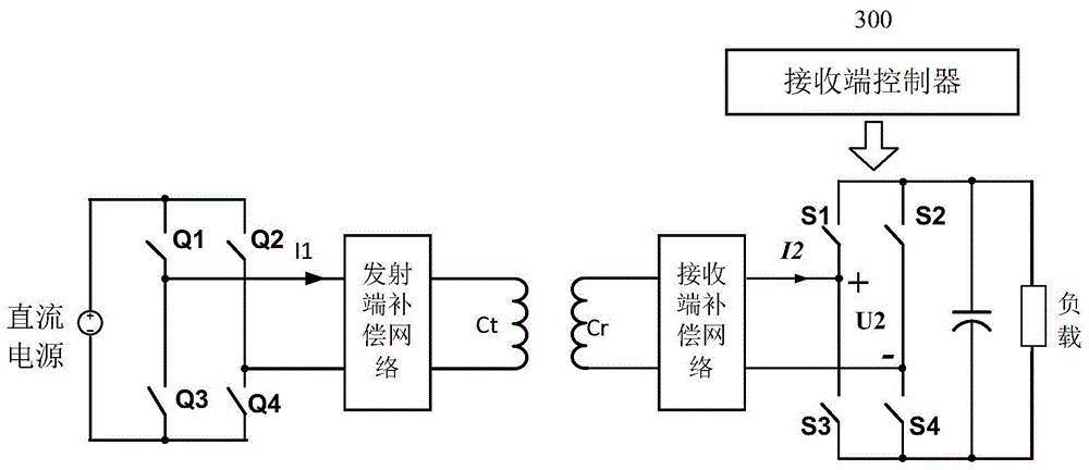
无线充电系统包括发射端和接收端。其中发射端包括:逆变器H1、发射端补偿网络100、发射端控制器400和发射线圈Ct。接收端包括:整流器H2、接收端补偿网络200和接收端控制器300。The wireless charging system includes a transmitter and a receiver. The transmitting end includes: an inverter H1, a transmitting
由于H1连接的是直流电源,因此H1用于将直流电逆变为交流电。发射端补偿网络100对H1输出的交流电进行补偿后输出给发射线圈Ct,发射线圈Ct用于将所述交流电以交变磁场形式发射出去。Since H1 is connected to a DC power supply, H1 is used to invert DC power into AC power. The transmitting
接收端的接收线圈Cr用于接收交变磁场并输出交流电,接收端补偿网络200用于对交流电进行补偿后输出给整流器H2,H2用于将交流电整流为直流电提供给负载。The receiving coil Cr at the receiving end is used to receive the alternating magnetic field and output alternating current. The receiving
其中,H1包括四个可控开关管Q1-Q4,H2包括四个可控开关管S1-S4。Wherein, H1 includes four controllable switch tubes Q1-Q4, and H2 includes four controllable switch tubes S1-S4.
由于可控开关管在开关过程中会产生损耗,因此,希望可控开关管在开关过程中产生的损耗越少越好,从而可以提高无线充电系统的工作效率。Since the controllable switching tube will generate loss during switching, it is hoped that the controllable switching tube will generate as little loss as possible during switching, so that the working efficiency of the wireless charging system can be improved.
发明内容Contents of the invention
为了解决现有技术中存在的以上技术问题,本发明提供一种无线充电系统的接收端、发射端及无线充电系统,能够保证发射端的逆变器实现零电压开关,降低可控开关管产生的损耗,从而提升无线充电系统的工作效率。In order to solve the above technical problems in the prior art, the present invention provides a receiving end, a transmitting end and a wireless charging system of a wireless charging system, which can ensure that the inverter at the transmitting end realizes zero-voltage switching, and reduces the voltage generated by the controllable switching tube. Loss, thereby improving the working efficiency of the wireless charging system.
第一方面,本申请实施例提供一种无线充电系统的接收端,包括:接收线圈、整流器和接收端控制器;接收线圈接收交变磁场并输出交流电;整流器将来自接收线圈的交流电整流为直流电;接收端控制器根据发射端控制器发送的目标阻抗调节接收端反射到发射端的反射阻抗以使发射端的逆变器实现零电压开关;整流器可以为全桥整流器,也可以为半桥整流器,当整流器为全桥整流器时,桥臂电压为全桥整流器的两个桥臂中点之间的电压;当整流器为半桥整流器时,桥臂电压为半桥整流器的单个桥臂中点与地之间的电压。In the first aspect, an embodiment of the present application provides a receiving end of a wireless charging system, including: a receiving coil, a rectifier, and a receiving end controller; the receiving coil receives an alternating magnetic field and outputs alternating current; the rectifier rectifies the alternating current from the receiving coil into direct current ; The controller at the receiving end adjusts the reflection impedance reflected from the receiving end to the transmitting end according to the target impedance sent by the controller at the transmitting end so that the inverter at the transmitting end can realize zero-voltage switching; the rectifier can be a full-bridge rectifier or a half-bridge rectifier. When the rectifier is a full-bridge rectifier, the bridge arm voltage is the voltage between the midpoints of the two bridge arms of the full-bridge rectifier; when the rectifier is a half-bridge rectifier, the bridge arm voltage is the voltage between the midpoint of a single bridge arm of the half-bridge rectifier and the ground voltage between.
该接收端通过调节接收端反射到发射端的反射阻抗,进而调节发射端的逆变器的等效输出阻抗,从而使逆变器的可控开关管实现零电压开关而接收端调节反射阻抗是以发射端发送的目标阻抗为基础,即发射端需要的反射阻抗作为目标阻抗,使接收端根据目标阻抗调节自身的实际反射阻抗使其满足发射端的要求。当逆变器的等效输出阻抗呈现阻感性时,可以使逆变器的可控开关管实现零电压开关。The receiving end adjusts the reflection impedance reflected from the receiving end to the transmitting end, and then adjusts the equivalent output impedance of the inverter at the transmitting end, so that the controllable switching tube of the inverter realizes zero-voltage switching, and the receiving end adjusts the reflection impedance to transmit Based on the target impedance sent by the terminal, that is, the reflection impedance required by the transmitting terminal is used as the target impedance, so that the receiving terminal adjusts its actual reflection impedance according to the target impedance to meet the requirements of the transmitting terminal. When the equivalent output impedance of the inverter is resistive and inductive, the controllable switching tube of the inverter can realize zero-voltage switching.
优选地,接收端控制器具体用于:根据目标阻抗获得对应的整流器的目标输入阻抗;获得整流器的等效输入阻抗,将整流器的目标输入阻抗和等效输入阻抗进行比较,根据比较结果调整整流器的输入电流与桥臂电压之间的相位差,以使反射阻抗与目标阻抗一致。Preferably, the receiving-end controller is specifically used to: obtain the target input impedance of the corresponding rectifier according to the target impedance; obtain the equivalent input impedance of the rectifier, compare the target input impedance of the rectifier with the equivalent input impedance, and adjust the rectifier according to the comparison result The phase difference between the input current and the bridge arm voltage makes the reflected impedance consistent with the target impedance.
调整整流器的输入电流与桥臂电压之间的相位差,目的是使接收端的反射阻抗与目标阻抗一致。The phase difference between the input current of the rectifier and the voltage of the bridge arm is adjusted to make the reflected impedance of the receiving end consistent with the target impedance.
其中,整流器的等效输入阻抗可以根据整流器的输入电流和桥臂电压获得,即桥臂电压除以输入电流即为等效输入阻抗。Wherein, the equivalent input impedance of the rectifier can be obtained according to the input current of the rectifier and the bridge arm voltage, that is, the equivalent input impedance is obtained by dividing the bridge arm voltage by the input current.
优选地,接收端控制器具体用于:将整流器的等效输入阻抗与目标输入阻抗进行比较,当整流器的等效输入阻抗呈现的容性大于目标输入阻抗呈现的容性时,减小整流器的输入电流和桥臂电压之间的相位差,反之增大加整流器的输入电流和桥臂电压之间的相位差。Preferably, the receiving-end controller is specifically configured to: compare the equivalent input impedance of the rectifier with the target input impedance, and reduce the rectifier's capacitance when the equivalent input impedance of the rectifier presents a capacitance greater than the capacitance presented by the target input impedance. The phase difference between the input current and the bridge arm voltage, on the contrary, increases the phase difference between the input current of the rectifier and the bridge arm voltage.
优选地,整流器的等效输入阻抗呈现的容性大于目标阻抗呈现的容性,具体为:整流器的等效输入阻抗的虚部为负值,目标阻抗的虚部为负值,且整流器的等效输入阻抗的虚部的绝对值大于目标阻抗的虚部的绝对值。Preferably, the equivalent input impedance of the rectifier exhibits a greater capacitance than the target impedance, specifically: the imaginary part of the equivalent input impedance of the rectifier is negative, the imaginary part of the target impedance is negative, and the rectifier is equal to The absolute value of the imaginary part of the effective input impedance is greater than the absolute value of the imaginary part of the target impedance.
优选地,还包括:接收端LCC补偿网络;接收端LCC补偿网络连接在接收线圈和整流器之间,用于将接收线圈输出的交流电进行补偿后发送给整流器。Preferably, it also includes: a receiving end LCC compensation network; the receiving end LCC compensation network is connected between the receiving coil and the rectifier, and is used to compensate the alternating current output by the receiving coil and send it to the rectifier.
LCC补偿网络包括三个支路,即一个感性支路和两个容性支路,而且三个支路所呈现的阻抗模值相等。一般接收端和发射端的补偿网络的架构相同,即均为LCC补偿网络。The LCC compensation network includes three branches, that is, one inductive branch and two capacitive branches, and the impedance modulus values presented by the three branches are equal. Generally, the structure of the compensation network at the receiving end and the transmitting end is the same, that is, both are LCC compensation networks.
优选地,接收端控制器,具体用于根据目标阻抗、接收端LCC补偿网络中各支路的阻抗的模值、以及发射线圈和接收线圈之间的互感获得整流器的目标输入阻抗。Preferably, the controller at the receiving end is specifically configured to obtain the target input impedance of the rectifier according to the target impedance, the impedance modulus of each branch in the LCC compensation network at the receiving end, and the mutual inductance between the transmitting coil and the receiving coil.
第二方面,本申请实施例还提供一种无线充电系统的发射端,包括:发射线圈、逆变器和发射端控制器;逆变器将直流电源输出的直流电逆变为交流电;发射线圈将交流电以交变磁场的形式进行发射;发射端控制器根据逆变器的输入电压、逆变器的两个桥臂之间的相位差和无线充电系统需要输出的功率获得目标阻抗,将目标阻抗发送给接收端控制器,以使接收端控制器控制接收端的反射阻抗与目标阻抗一致。In the second aspect, the embodiment of the present application also provides a transmitter of a wireless charging system, including: a transmitter coil, an inverter, and a transmitter controller; the inverter inverts the DC power output by the DC power supply into AC power; the transmitter coil The alternating current is transmitted in the form of an alternating magnetic field; the transmitter controller obtains the target impedance according to the input voltage of the inverter, the phase difference between the two bridge arms of the inverter and the output power required by the wireless charging system, and converts the target impedance to Send it to the controller at the receiving end, so that the controller at the receiving end controls the reflected impedance of the receiving end to be consistent with the target impedance.
发射端可以获得自身需要的反射阻抗,作为目标阻抗发送给接收端控制器,通过接收端反射的反射阻抗来使发射端的逆变器的等效输出阻抗呈现阻感性时,可以使逆变器的可控开关管实现零电压开关。The transmitter can obtain the reflection impedance it needs, and send it to the receiver controller as the target impedance. When the reflection impedance reflected by the receiver is used to make the equivalent output impedance of the inverter at the transmitter appear resistive and inductive, the inverter’s The controllable switching tube realizes zero voltage switching.
优选地,发射端控制器,还用于根据发射端的输出电压和输出电流获得接收端的反射阻抗,将接收端的反射阻抗与目标阻抗进行比较,如果一致,则向接收端控制器发送结束调整整流器的输入电流和桥臂电压之间的相位差。Preferably, the transmitting end controller is also used to obtain the reflected impedance of the receiving end according to the output voltage and output current of the transmitting end, compare the reflected impedance of the receiving end with the target impedance, and if they are consistent, send the end adjustment rectifier to the receiving end controller The phase difference between the input current and the bridge arm voltage.
第三方面,本申请实施例还提供一种无线充电系统,包括动力电池组、以上介绍的接收端和以上介绍的发射端;接收端为动力电池组进行充电。In the third aspect, the embodiment of the present application further provides a wireless charging system, including a power battery pack, the receiving end described above, and the transmitting end described above; the receiving end charges the power battery pack.
与现有技术相比,本发明至少具有以下优点:Compared with the prior art, the present invention has at least the following advantages:
该接收端通过调节接收端反射到发射端的反射阻抗,进而调节发射端的逆变器的等效输出阻抗,从而使逆变器的可控开关管实现零电压开关(ZVS,Zero Voltage Switch)。而接收端调节反射阻抗是以发射端发送的目标阻抗为基础,即发射端需要的反射阻抗作为目标阻抗,使接收端根据目标阻抗调节自身的实际反射阻抗使其满足发射端的要求。当逆变器的等效输出阻抗呈现阻感性时,可以使逆变器的可控开关管实现ZVS。当逆变器的可控开关管实现ZVS时,可以降低可控开关管在工作过程中产生的功耗,进而提升无线充电系统的工作效率。The receiving end adjusts the reflection impedance reflected from the receiving end to the transmitting end, and then adjusts the equivalent output impedance of the inverter at the transmitting end, so that the controllable switching tube of the inverter realizes zero voltage switching (ZVS, Zero Voltage Switch). The receiver adjusts the reflection impedance based on the target impedance sent by the transmitter, that is, the reflection impedance required by the transmitter is used as the target impedance, so that the receiver can adjust its actual reflection impedance according to the target impedance to meet the requirements of the transmitter. When the equivalent output impedance of the inverter is resistive and inductive, the controllable switching tube of the inverter can realize ZVS. When the controllable switching tube of the inverter realizes ZVS, the power consumption generated by the controllable switching tube during the working process can be reduced, thereby improving the working efficiency of the wireless charging system.
附图说明Description of drawings
为了更清楚地说明本申请实施例或现有技术中的技术方案,下面将对实施例或现有技术描述中所需要使用的附图作简单地介绍,显而易见地,下面描述中的附图仅仅是本申请中记载的一些实施例,对于本领域普通技术人员来讲,在不付出创造性劳动的前提下,还可以根据这些附图获得其它的附图。In order to more clearly illustrate the technical solutions in the embodiments of the present application or the prior art, the following will briefly introduce the drawings that need to be used in the description of the embodiments or the prior art. Obviously, the accompanying drawings in the following description are only These are some embodiments described in this application. Those skilled in the art can also obtain other drawings based on these drawings without creative work.
图1为一种无线充电系统的示意图;1 is a schematic diagram of a wireless charging system;
图2为本申请实施例提供的一种无线充电系统的接收端的示意图;FIG. 2 is a schematic diagram of a receiving end of a wireless charging system provided by an embodiment of the present application;
图3为本申请实施例提供的整流器的桥臂电压和输入电流的波形图;FIG. 3 is a waveform diagram of the bridge arm voltage and input current of the rectifier provided in the embodiment of the present application;
图4为本申请实施例提供的补偿网络为LCC结构的示意图;FIG. 4 is a schematic diagram of a compensation network provided by an embodiment of the present application as an LCC structure;
图5为本申请实施例提供的发射端和接收端均是LCC补偿网络的示意图;FIG. 5 is a schematic diagram of an LCC compensation network in which both the transmitting end and the receiving end are provided by the embodiment of the present application;
图6为本申请实施例提供的补偿网络为LCC无线充电系统等效示意图;Fig. 6 is an equivalent schematic diagram of the compensation network provided by the embodiment of the present application as the LCC wireless charging system;
图7为本申请实施例提供的接收端控制器调节反射阻抗的流程图;FIG. 7 is a flow chart of adjusting reflection impedance by a receiver controller provided in an embodiment of the present application;
图8a本申请实施例提供的接收端的等效电路图;Fig. 8a is an equivalent circuit diagram of the receiving end provided by the embodiment of the present application;
图8b为本申请实施例提供的无线充电系统中的发射端示意图;Fig. 8b is a schematic diagram of the transmitter in the wireless charging system provided by the embodiment of the present application;
图9为本申请实施例提供的发射端的等效电路图;FIG. 9 is an equivalent circuit diagram of the transmitting end provided by the embodiment of the present application;
图10为与图9对应的第三支路的电压和电流的波形图;Fig. 10 is the waveform diagram of the voltage and current of the third branch corresponding to Fig. 9;
图11为本申请实施例提供的逆变器的桥臂电压U1和整流器的桥臂电压U2的相差为2.75us对应的波形图;Fig. 11 is a waveform diagram corresponding to a phase difference of 2.75us between the bridge arm voltage U1 of the inverter and the bridge arm voltage U2 of the rectifier provided by the embodiment of the present application;
图12为本申请实施例提供的逆变器的桥臂电压U1和整流器的桥臂电压U2的相差为1.75us对应的波形图。FIG. 12 is a waveform diagram corresponding to a phase difference of 1.75 μs between the bridge arm voltage U1 of the inverter and the bridge arm voltage U2 of the rectifier provided by the embodiment of the present application.
具体实施方式Detailed ways
为了使本领域技术人员更好地理解本申请实施例提供的技术方案,下面首先介绍应用场景,本申请实施例提供的接收端,应用于无线充电系统,具体可以参见图1,该图为一种无线充电系统的示意图。In order for those skilled in the art to better understand the technical solutions provided by the embodiments of the present application, the following first introduces the application scenarios. The receiving end provided by the embodiments of the present application is applied to a wireless charging system. For details, please refer to Figure 1, which is a A schematic diagram of a wireless charging system.
无线充电系统可以为用电终端以无线形式进行充电,即发射端和接收端不是通过有线进行连接,而是通过无线形式进行交变磁场的交互来传递电磁能量。The wireless charging system can charge the electricity terminal in a wireless form, that is, the transmitting end and the receiving end are not connected by wires, but by interacting with the alternating magnetic field in a wireless form to transfer electromagnetic energy.
实际应用中,无线充电系统的发射端一般包括:逆变器H1、发射端补偿电路100和发射线圈Ct。图1中的H1包括四个可控开关管,分别为Q1-Q4。其中逆变器H1的作用是将直流电源输出的直流电逆变为交流电;发射端补偿电路100的作用对交流电进行补偿后输出给发射线圈Ct;发射线圈Ct的作用将所述交流电以交变磁场形式进行发射,以使接收线圈Cr通过无线形式接收交变磁场。In practical application, the transmitting end of the wireless charging system generally includes: an inverter H1 , a transmitting
接收端包括接收线圈Cr、接收端补偿网络200和整流器H2。接收线圈Cr用于接收来自发射线圈Ct的交变磁场并输出交流电。接收端补偿网络200用于对交流电进行补偿输出给整流器H2。整流器H2包括可控开关管S1-S4。其中,接收端控制器300与发射端控制器400进行无线通讯。The receiving end includes a receiving coil Cr, a receiving
可以理解的是,整流器H2可以为全桥整流器,也可以为半桥整流器。当整流器为全桥整流器时,四个开关管可以全部为可控开关管,也可以包括两个可控开关管,两个不可控的二极管。It can be understood that the rectifier H2 can be a full-bridge rectifier or a half-bridge rectifier. When the rectifier is a full-bridge rectifier, all of the four switch tubes may be controllable switch tubes, or may include two controllable switch tubes and two uncontrollable diodes.
发射端的控制器400和接收端的控制器300之间进行无线通信。无线通讯的方式可以包括但不仅限于以下方式中的任意一种或多种的组合:Wireless communication is performed between the
蓝牙(bluetooth)、无线宽带(WIreless-Fidelity,WiFi)、紫蜂协议(Zigbee)、射频识别技术(Radio Frequency Identification,RFID)、远程(Long Range,Lora)无线技术和近距离无线通信技术(Near Field Communication,NFC)。Bluetooth (bluetooth), wireless broadband (WIreless-Fidelity, WiFi), Zigbee protocol (Zigbee), radio frequency identification technology (Radio Frequency Identification, RFID), long-range (Long Range, Lora) wireless technology and short-range wireless communication technology (Near Field Communication, NFC).
对于无线充电系统发射端的逆变器来说,为了保证逆变器的可控开关管实现零电压开关(Zero Voltage Switch,ZVS)效果,逆变器实现ZVS需要其等效输出阻抗呈现一定的阻感性,即逆变器能够输出一定的无功功率,感性的大小要合适。ZVS是指可控开关管在关断和导通时,其两端的电压理想数值为0,当然实际应用中两端的电压可能为比较小的一个电压,电压越小则功耗越低。感性不足会导致逆变器失去ZVS效果,造成开关损耗增加,甚至造成逆变器损坏。感性过大,则逆变器输出的无功功率较大,会导致逆变器导通损耗增加,效率降低。因此,如何使发射端的逆变器实现ZVS,从而实现无线充电系统效率优化。For the inverter at the transmitting end of the wireless charging system, in order to ensure that the controllable switching tube of the inverter realizes the effect of zero voltage switching (Zero Voltage Switch, ZVS), the equivalent output impedance of the inverter needs to present a certain resistance to realize ZVS. Inductive, that is, the inverter can output a certain amount of reactive power, and the inductive size should be appropriate. ZVS means that when the controllable switch is turned off and on, the ideal value of the voltage at both ends is 0. Of course, the voltage at both ends may be a relatively small voltage in practical applications. The smaller the voltage, the lower the power consumption. Insufficient inductance will cause the inverter to lose the ZVS effect, resulting in increased switching loss and even damage to the inverter. If the inductance is too large, the reactive power output by the inverter will be large, which will lead to an increase in the conduction loss of the inverter and a decrease in efficiency. Therefore, how to make the inverter at the transmitting end realize ZVS, so as to realize the efficiency optimization of the wireless charging system.
本申请实施例提供的技术方案,通过调整接收端反射到发射端的反射阻抗,从而使发射端的逆变器的可控开关管实现ZVS。In the technical solution provided by the embodiments of the present application, by adjusting the reflection impedance reflected from the receiving end to the transmitting end, the controllable switching tube of the inverter at the transmitting end can realize ZVS.
为了使本技术领域的人员更好地理解本发明方案,下面将结合本发明实施例中的附图,对本发明实施例中的技术方案进行清楚、完整地描述。In order to enable those skilled in the art to better understand the solutions of the present invention, the technical solutions in the embodiments of the present invention will be clearly and completely described below in conjunction with the drawings in the embodiments of the present invention.
接收端实施例一:Receiver embodiment one:
参见图2,该图为本申请实施例提供的一种无线充电系统的接收端的示意图。Referring to FIG. 2 , this figure is a schematic diagram of a receiving end of a wireless charging system provided by an embodiment of the present application.
本实施例提供的无线充电系统的接收端,包括:接收线圈Cr、整流器和接收端控制器300;The receiving end of the wireless charging system provided in this embodiment includes: a receiving coil Cr, a rectifier, and a receiving
接收线圈接收交变磁场并输出交流电;The receiving coil receives the alternating magnetic field and outputs alternating current;
整流器将来自接收线圈的交流电整流为直流电;The rectifier rectifies the alternating current from the receiving coil to direct current;
其中,整流器可以为全桥整流器,也可以为半桥整流器。当整流器为全桥整流器时,四个开关管可以全部为可控开关管,如图2所示的可控开关管S1-S4,也可以包括两个可控开关管,两个不可控的二极管。Wherein, the rectifier may be a full-bridge rectifier or a half-bridge rectifier. When the rectifier is a full-bridge rectifier, the four switching tubes can all be controllable switching tubes, such as the controllable switching tubes S1-S4 shown in Figure 2, or two controllable switching tubes and two uncontrollable diodes .
接收端控制器300根据发射端控制器发送的目标阻抗调节所述接收端反射到所述发射端的反射阻抗以使所述发射端的逆变器实现零电压开关;所述整流器为全桥整流器时,所述桥臂电压为所述全桥整流器的两个桥臂中点之间的电压;如图2所示,S1和S3组成第一桥臂,S2和S4组成第二桥臂,第一桥臂中点是指S1和S3的公共端,第二桥臂的中点是S2和S4的公共端。整流器为半桥整流器时,桥臂电压为半桥整流器的单个桥臂中点与地之间的电压。The receiving
可以理解的是,发射端和接收端均设置无线通信模块,发射端控制器和接收端控制器300之间通过各自对应的无线通信模块进行通信。例如,发射端控制器通过发射端的无线通信模块将目标阻抗发送给接收端的无线通信模块,接收端的无线通信模块将接收到的目标阻抗再发给接收端控制器300。It can be understood that both the transmitting end and the receiving end are equipped with wireless communication modules, and the transmitting end controller and the receiving
如图2所示,发射端的逆变器包括四个可控开关管Q1-Q4。As shown in FIG. 2, the inverter at the transmitting end includes four controllable switch tubes Q1-Q4.
由于发射端的逆变器包括可控开关管,因此需要使可控开关管实现ZVS,从而降低可控开关管在动作过程中产生的功耗。Since the inverter at the transmitting end includes a controllable switch tube, it is necessary to enable the controllable switch tube to realize ZVS, thereby reducing power consumption generated by the controllable switch tube during operation.
本申请实施例中是通过调节接收端反射到发射端的反射阻抗,进而实现调节发射端的逆变器的等效输出阻抗,控制逆变器的可控开关管实现ZVS。而接收端调节反射阻抗是以发射端发送的目标阻抗为基础,即发射端需要的反射阻抗作为目标阻抗,使接收端调节自身的反射阻抗使其满足发射端的要求。当逆变器的等效输出阻抗呈现阻感性时,可以使逆变器的可控开关管实现ZVS。In the embodiment of the present application, the equivalent output impedance of the inverter at the transmitting end is adjusted by adjusting the reflection impedance reflected from the receiving end to the transmitting end, and the controllable switching tube of the inverter is controlled to realize ZVS. The receiver adjusts the reflection impedance based on the target impedance sent by the transmitter, that is, the reflection impedance required by the transmitter is used as the target impedance, so that the receiver can adjust its own reflection impedance to meet the requirements of the transmitter. When the equivalent output impedance of the inverter is resistive and inductive, the controllable switching tube of the inverter can realize ZVS.
调节接收端的反射阻抗主要是通过调节整流器的桥臂电压和输入电流的相位差来实现,具体可以参见图3,该图为整流器的桥臂电压和输入电流的波形图。Adjusting the reflected impedance at the receiving end is mainly achieved by adjusting the phase difference between the bridge arm voltage of the rectifier and the input current. For details, please refer to Figure 3, which is a waveform diagram of the bridge arm voltage and input current of the rectifier.
图3中U2为整流器的桥臂电压,I2为整流器的输入电流。In Fig. 3, U2 is the bridge arm voltage of the rectifier, and I2 is the input current of the rectifier.
从图中可以看出,桥臂电压U2的相位滞后输入电流I2的相位,其中滞后的角度为θ,即整流器的桥臂电压和输入电流的相位差为θ。该相位差θ可以根据需要来调整。当U2的相位滞后I2时,可以使整流器的等效输入阻抗呈现阻容性。It can be seen from the figure that the phase of the bridge arm voltage U2 lags behind the phase of the input current I2, and the lag angle is θ, that is, the phase difference between the bridge arm voltage of the rectifier and the input current is θ. The phase difference θ can be adjusted as needed. When the phase of U2 lags behind I2, the equivalent input impedance of the rectifier can be shown as resistance-capacitance.
本实施例提供的接收端还包括:接收端LCC补偿网络;接收端LCC补偿网络连接在接收线圈和整流器之间,用于将接收线圈输出的交流电进行补偿后发送给整流器。The receiving end provided in this embodiment further includes: an LCC compensation network at the receiving end; the LCC compensation network at the receiving end is connected between the receiving coil and the rectifier, and is used to compensate the alternating current output by the receiving coil and send it to the rectifier.
需要说明的是,本申请实施例提供的技术方案以应用于发射端和接收端的补偿网络均为LCC结构为例进行介绍,可以理解的是,发射端和接收端的补偿网络除了LCC结构以外,还可以为LC结构,单C结构等,在此不再赘述。It should be noted that the technical solution provided by the embodiment of the present application is introduced by taking the compensation network applied to both the transmitting end and the receiving end as an example with an LCC structure. It can be understood that, in addition to the LCC structure, the compensation networks at the transmitting end and the receiving end also have It can be an LC structure, a single C structure, etc., which will not be repeated here.
具体可以参见图4,该图为补偿网络为LCC结构的示意图。For details, refer to FIG. 4 , which is a schematic diagram of a compensation network with an LCC structure.
从图中可以看出,LCC包括一个电感L和两个电容C。It can be seen from the figure that the LCC includes an inductor L and two capacitors C.
对于发射端和接收端的补偿网络均是LCC结构的无线充电系统,具体可以参见图5所示,该图为本申请实施例提供的发射端和接收端均是LCC补偿网络的示意图。从图5可以看出,发射端包括LCC,接收端也包括LCC。For a wireless charging system in which both the compensation network of the transmitting end and the receiving end are LCC structures, please refer to FIG. 5 for details, which is a schematic diagram of an LCC compensation network provided by the embodiment of the present application. It can be seen from FIG. 5 that the transmitting end includes the LCC, and the receiving end also includes the LCC.
接收端实施例二:Receiver embodiment two:
参见图6,该图为本申请实施例提供的补偿网络为LCC无线充电系统等效示意图。Referring to FIG. 6 , this figure is an equivalent schematic diagram of a wireless charging system in which the compensation network provided by the embodiment of the present application is an LCC.
将发射端的逆变器等效为一个交变电压源,将接收端的整流器等效为一个可变负载Z2。以发射端和接收端的补偿网络均为LCC为例,可以获得等效电路如图6所示。The inverter at the transmitting end is equivalent to an alternating voltage source, and the rectifier at the receiving end is equivalent to a variable load Z2. Taking the compensation network at both the transmitting end and the receiving end as LCC as an example, the equivalent circuit can be obtained as shown in Figure 6.
接收端控制器调整整流器的等效输入阻抗进而调节反射阻抗,下面结合流程图来详细介绍其工作原理。The controller at the receiving end adjusts the equivalent input impedance of the rectifier and then adjusts the reflected impedance. The following describes its working principle in detail in conjunction with the flow chart.
参见图7,该图为本申请实施例提供的接收端控制器调节反射阻抗的流程图。Referring to FIG. 7 , this figure is a flow chart of adjusting reflection impedance by a receiver controller provided in an embodiment of the present application.
S701:接收端控制器接收发射端控制器发送的目标阻抗。S701: The receiving-end controller receives the target impedance sent by the transmitting-end controller.
S702:接收端控制器根据目标阻抗获得对应的整流器的目标输入阻抗。S702: The receiving-end controller obtains the corresponding target input impedance of the rectifier according to the target impedance.
接收端控制器获得整流器的目标输入阻抗后,需要先判断该目标输入阻抗是否在接收端可调节的阻抗范围之内,如果否,则等待发射端控制器发送新的目标阻抗。如果是,则进行S704。After obtaining the target input impedance of the rectifier, the receiving-end controller needs to judge whether the target input impedance is within the adjustable impedance range of the receiving end, and if not, wait for the transmitting-end controller to send a new target impedance. If yes, go to S704.
S703:接收端控制器获得整流器的等效输入阻抗。S703: The receiving-end controller obtains the equivalent input impedance of the rectifier.
接收端控制器具体是根据整流器的输入电流和桥臂电压获得整流器的等效输入阻抗,即桥臂电压除以输入电流为整流器的等效输入阻抗。Specifically, the receiver controller obtains the equivalent input impedance of the rectifier according to the input current of the rectifier and the bridge arm voltage, that is, dividing the bridge arm voltage by the input current is the equivalent input impedance of the rectifier.
S704:比较整流器的目标输入阻抗和等效输入阻抗的容性大小。S704: Comparing the target input impedance of the rectifier with the capacitive value of the equivalent input impedance.
S705:当整流器的等效输入阻抗呈现的容性大于目标输入阻抗呈现的容性时,则减小整流器的输入电流和桥臂电压之间的相位差,反之增大加整流器的输入电流和桥臂电压之间的相位差。S705: When the capacitance presented by the equivalent input impedance of the rectifier is greater than the capacitance presented by the target input impedance, reduce the phase difference between the input current of the rectifier and the voltage of the bridge arm, otherwise increase the input current of the rectifier and the bridge arm The phase difference between the arm voltages.
整流器的等效输入阻抗呈现的容性大于目标阻抗呈现的容性,具体为:The equivalent input impedance of the rectifier exhibits a greater capacitance than the target impedance, as:
整流器的等效输入阻抗的虚部为负值,目标阻抗的虚部为负值,且整流器的等效输入阻抗的虚部的绝对值大于目标阻抗的虚部的绝对值。The imaginary part of the equivalent input impedance of the rectifier is negative, the imaginary part of the target impedance is negative, and the absolute value of the imaginary part of the equivalent input impedance of the rectifier is greater than the absolute value of the imaginary part of the target impedance.
例如,利用Z2表示整流器的等效输入阻抗,Z2=R2+jIm2,其中R2表示实部,表示阻性部分,R2上流过的电流与其两端的电压的相位相同。Im2是虚部,表示容性部分或感性部分。当Im2>0时,表示虚部为正,为感性阻抗,此时Im2上的电流相位滞后于电压相位90度。如果Im<0时表示虚部为负,为容性阻抗,此时Im2上的电流相位超前电压相位90度。容性大是指Im2的绝对值比较大。For example, use Z2 to represent the equivalent input impedance of the rectifier, Z2=R2+jIm2, where R2 represents the real part, which represents the resistive part, and the phase of the current flowing through R2 is the same as the voltage at both ends. Im2 is the imaginary part, which means the capacitive part or the inductive part. When Im2>0, it means that the imaginary part is positive, which is an inductive impedance. At this time, the current phase on Im2 lags behind the voltage phase by 90 degrees. If Im<0, it means that the imaginary part is negative, which is a capacitive impedance. At this time, the current phase on Im2 leads the voltage phase by 90 degrees. Large capacity means that the absolute value of Im2 is relatively large.
调整整流器的输入电流与桥臂电压之间的相位差,目的是使接收端的反射阻抗与目标阻抗一致。The phase difference between the input current of the rectifier and the voltage of the bridge arm is adjusted to make the reflected impedance of the receiving end consistent with the target impedance.
本实施例中接收端通过调整整流器的输入电流和桥臂电压之间的相位差来调整整流器的等效输入阻抗的容性大小。因为调整整流器的等效输入阻抗的容性可以调节接收端反射到发射端的反射阻抗的大小,进而使接收端实际反射到发射端的反射阻抗与发射端需要的反射阻抗一致,才可以保证发射端的逆变器实现ZVS。本实施例中通过调节接收端的反射阻抗来实现逆变器的ZVS,即将整流器看作一个可变阻抗的负载,并不需要调整逆变器自身的阻抗。In this embodiment, the receiving end adjusts the capacitive value of the equivalent input impedance of the rectifier by adjusting the phase difference between the input current of the rectifier and the bridge arm voltage. Because adjusting the capacitance of the equivalent input impedance of the rectifier can adjust the size of the reflection impedance reflected from the receiving end to the transmitting end, so that the reflection impedance actually reflected from the receiving end to the transmitting end is consistent with the reflection impedance required by the transmitting end, so that the inverse impedance of the transmitting end can be guaranteed. The transformer realizes ZVS. In this embodiment, the ZVS of the inverter is realized by adjusting the reflection impedance of the receiving end, that is, the rectifier is regarded as a variable impedance load, and the impedance of the inverter itself does not need to be adjusted.
所述接收端控制器,具体用于根据所述目标阻抗、所述接收端LCC补偿网络中各支路的阻抗的模值、以及发射线圈和接收线圈之间的互感获得所述整流器的目标输入阻抗。The receiving end controller is specifically configured to obtain the target input of the rectifier according to the target impedance, the modulus value of the impedance of each branch in the receiving end LCC compensation network, and the mutual inductance between the transmitting coil and the receiving coil impedance.
下面结合附图介绍接收端控制器获得目标输入阻抗的过程。The process of obtaining the target input impedance by the controller at the receiving end will be described below with reference to the accompanying drawings.
参见图8a,该图为本申请实施例提供的接收端的等效电路图。Referring to FIG. 8a, the figure is an equivalent circuit diagram of the receiving end provided by the embodiment of the present application.
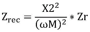
图8a为接收端LCC补偿网络对应的等效电路,目标阻抗Zr包括实部Rzr和虚部Xzr,如下公式所示。整流器的目标输入阻抗Zrec可以由以下公式获得,其中X2为接收端LCC补偿网络中各支路的阻抗模值,模值是指阻抗的绝对值。M为发射线圈和接收线圈之间的互感。Figure 8a is an equivalent circuit corresponding to the LCC compensation network at the receiving end, and the target impedance Zr includes a real part Rzr and an imaginary part Xzr, as shown in the following formula. The target input impedance Zrec of the rectifier can be obtained by the following formula, where X2 is the impedance modulus value of each branch in the LCC compensation network at the receiving end, and the modulus value refers to the absolute value of the impedance. M is the mutual inductance between the transmitting coil and the receiving coil.
Zr=RZr+j*XZr Z r =R Zr +j*X Zr
基于以上实施例提供的一种无线充电系统的接收端,本申请实施例还提供一种无线充电系统的发射端,下面结合附图进行详细说明。Based on the receiving end of the wireless charging system provided in the above embodiments, the embodiment of the present application also provides a transmitting end of the wireless charging system, which will be described in detail below with reference to the accompanying drawings.
发射端实施例一:
参见图8b,该图为本申请实施例提供的无线充电系统中的发射端示意图。Referring to FIG. 8b , this figure is a schematic diagram of the transmitter in the wireless charging system provided by the embodiment of the present application.
本实施例提供的无线充电系统的发射端,包括发射线圈Ct、逆变器H1和发射端控制器300;The transmitting end of the wireless charging system provided in this embodiment includes a transmitting coil Ct, an inverter H1 and a transmitting
所述逆变器H1,用于将直流电源输出的直流电逆变为交流电;可以理解的是,当无线充电系统的应用领域为电动汽车时,发射端设置于地面,接收端设置在电动汽车上,发射端与接收端之间通过无线方式进行通信,而且通过无线方式进行充电,具体为交变磁场进行能量的传递。The inverter H1 is used to invert the DC power output by the DC power supply into AC power; it can be understood that when the application field of the wireless charging system is an electric vehicle, the transmitting end is set on the ground, and the receiving end is set on the electric vehicle , the transmitting end and the receiving end communicate through wireless means, and charge through wireless means, specifically the alternating magnetic field for energy transfer.
所述发射线圈Ct,用于将所述交流电以交变磁场的形式进行发射;The transmitting coil Ct is used to transmit the alternating current in the form of an alternating magnetic field;
所述发射端控制器300,用于根据所述逆变器H1的输入电压、所述逆变器H1的两个桥臂之间的相位差和无线充电系统需要输出的功率获得目标阻抗,将所述目标阻抗发送给所述接收端控制器400,以使所述接收端控制器400控制接收端的反射阻抗与所述目标阻抗一致。The
H1的两个桥臂分别为Q1和Q3组成的桥臂,以及,Q2和Q4组成的桥臂。The two bridge arms of H1 are respectively the bridge arm formed by Q1 and Q3, and the bridge arm formed by Q2 and Q4.
H1的输入电压是指直流电源的输出电压,下面结合发射端的等效电路图来介绍目标阻抗的获得方式。The input voltage of H1 refers to the output voltage of the DC power supply. The following describes how to obtain the target impedance in combination with the equivalent circuit diagram of the transmitter.
参见图9,该图为本申请实施例提供的发射端的等效电路图。Referring to FIG. 9 , this figure is an equivalent circuit diagram of the transmitting end provided by the embodiment of the present application.
其中,Uinv表示直流电源,使用Ubus表示Uinv的电压。Among them, Uinv represents the DC power supply, and Ubus represents the voltage of Uinv.
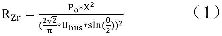
发射端控制器300根据Ubus、H1的两个桥臂之间的相位差以及接收端需要输出的功率Po获得目标阻抗,具体可以利用以下公式获得。The
其中目标阻抗的实部Rzr为公式(1);The real part Rzr of the target impedance is formula (1);
目标阻抗的虚部Xzr为公式(2);The imaginary part Xzr of the target impedance is formula (2);
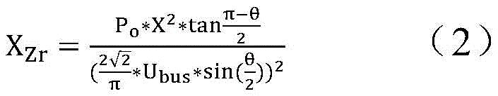
其中Po是无线充电系统需要输出的功率,例如,当应用于电动汽车领域时,由电动汽车的电池决定了Po的大小。Where Po is the output power that the wireless charging system needs to output. For example, when it is applied to the field of electric vehicles, the size of Po is determined by the battery of the electric vehicle.
可以理解的是,发射端控制器300根据公式(1)和(2)获得的是反射阻抗的目标阻抗,即需要接收端反射的反射阻抗的大小。但是实际工作中,接收端一般不会一次性调整反射阻抗就可以达到目标阻抗,因此,发射端控制器300,还用于根据发射端的输出电压和输出电流获得所述接收端的反射阻抗,将所述接收端的反射阻抗与所述目标阻抗进行比较,如果一致,则向所述接收端控制器400发送结束调整所述整流器的所述输入电流和所述桥臂电压之间的相位差。It can be understood that what the
下面结合图9介绍发射端控制器300获得实际反射阻抗的方式。The manner in which the
图9所示的等效电路图包括三个阻抗支路,分别为包括jX的第一支路,包括-jX的第二支路,以及包括jX和反射阻抗Z的第三支路。发射端LCC补偿网络的三个支路包括的阻抗的模值相等,即每个支路的阻抗均为X。The equivalent circuit diagram shown in FIG. 9 includes three impedance branches, namely a first branch including jX, a second branch including -jX, and a third branch including jX and reflection impedance Z. The modulus values of the impedances included in the three branches of the LCC compensation network at the transmitting end are equal, that is, the impedance of each branch is X.
发射端控制器300根据第三支路的电压和电流获得反射阻抗的大小。The
参见图10,为与图9对应的第三支路的电压和电流的波形图。Referring to FIG. 10 , it is a waveform diagram of the voltage and current of the third branch corresponding to FIG. 9 .
第三支路的电压超前第三支路的电流的相位为α。即第三支路的电压与电流之间的相位差为α。The phase of the voltage of the third branch leading the current of the third branch is α. That is, the phase difference between the voltage and current of the third branch is α.
则反射阻抗Z的实部=(发射线圈的电压峰值/发射线圈的电流峰值)*cosα;Then the real part of the reflected impedance Z=(voltage peak value of the transmitting coil/current peak value of the transmitting coil)*cosα;
反射阻抗Z的虚部=(发射线圈的电压峰值/发射线圈的电流峰值)*sinα-X;The imaginary part of the reflection impedance Z=(voltage peak value of the transmitting coil/current peak value of the transmitting coil)*sinα-X;
可以理解的是,公式(1)和(2)计算的是目标阻抗Zr的实部和虚部,而Z的实部和虚部是实际反射阻抗的实部和虚部。发射端控制器300可以根据实际反射阻抗的实部和虚部确定接收端是否需要继续调整整流器的桥臂电压和输入电流之间的相位差。当实际反射阻抗的实部和虚部分别与目标阻抗的实部和虚部一致时,则不必继续调整整流器的桥臂电压和输入电流之间的相位差。It can be understood that the formulas (1) and (2) calculate the real and imaginary parts of the target impedance Zr, and the real and imaginary parts of Z are the real and imaginary parts of the actual reflected impedance. The transmitting
无线充电系统实施例:Example of a wireless charging system:
基于以上实施例提供的一种无线充电系统的接收端和发射端,本申请实施例还提供一种无线充电系统,该无线充电系统包括以上实施例介绍的发射端和接收端。该无线充电系统还包括:动力电池组;Based on the receiving end and the transmitting end of a wireless charging system provided in the above embodiments, the embodiments of the present application further provide a wireless charging system, which includes the transmitting end and the receiving end introduced in the above embodiments. The wireless charging system also includes: a power battery pack;
所述接收端为所述动力电池组进行充电。The receiving end charges the power battery pack.
该无线充电系统应用于电动汽车领域时,接收端位于电动汽车上,接收端为电动汽车的动力电池组进行充电,即动力电池组为电动汽车提供能源为电动汽车上的电机供电,电机为电动汽车提供驱动力。When the wireless charging system is applied to the field of electric vehicles, the receiving end is located on the electric vehicle, and the receiving end charges the power battery pack of the electric vehicle, that is, the power battery pack provides energy for the electric vehicle to supply power for the motor on the electric vehicle, and the motor is an electric The car provides the driving force.
由于该无线充电系统包括的发射端可以实现逆变器的ZVS,从而降低逆变器的可控开关管在工作过程中产生的损耗,进而可以提高发射线圈和接收线圈的电能传输效率。Since the transmitting end included in the wireless charging system can realize the ZVS of the inverter, thereby reducing the loss generated by the controllable switching tube of the inverter during the working process, thereby improving the power transmission efficiency of the transmitting coil and the receiving coil.
为了直观了解本申请实施例提供的技术方案的有益效果,下面结合实验仿真波形图进行详细介绍。In order to intuitively understand the beneficial effects of the technical solutions provided by the embodiments of the present application, a detailed introduction will be made below in conjunction with experimental simulation waveform diagrams.
参见图11,该图为本申请实施例提供的逆变器的桥臂电压U1和整流器的桥臂电压U2的相差为2.75us对应的波形图。Refer to FIG. 11 , which is a waveform diagram corresponding to a phase difference of 2.75us between the bridge arm voltage U1 of the inverter and the bridge arm voltage U2 of the rectifier provided by the embodiment of the present application.
参见图12,该图为本申请实施例提供的逆变器的桥臂电压U1和整流器的桥臂电压U2的相差为1.75us对应的波形图。Refer to FIG. 12 , which is a waveform diagram corresponding to a phase difference of 1.75 μs between the bridge arm voltage U1 of the inverter and the bridge arm voltage U2 of the rectifier provided by the embodiment of the present application.
可以理解的是,U2的相位超前U1的相位。It can be understood that the phase of U2 is ahead of the phase of U1.
对比图11和图12,可以看出由于整流器的桥臂电压的超前角度减小,即从2.75us减小到1.75us,可以看出圆圈标识的I1电流线的负电流增加了,负电流越大越容易实现ZVS,因此更有利于发射端的逆变器的可控开关管实现ZVS。Comparing Figure 11 and Figure 12, it can be seen that because the leading angle of the bridge arm voltage of the rectifier decreases, that is, from 2.75us to 1.75us, it can be seen that the negative current of the I1 current line marked by the circle increases, and the more negative the current The larger the value, the easier it is to achieve ZVS, so it is more conducive to the realization of ZVS by the controllable switch tube of the inverter at the transmitting end.
可以看出,当接收侧的等效阻抗容性较大时(如1.75us时I2的正电流比2.75us时的正电流大,)会导致发射端的等效阻抗感性较大(如2.75us时I1的负电流比1.75us时的负电流小),这种情况下逆变器和整流器的导通损耗增加,因此,可以通过适当增大接收侧的超前角度来减小无功电流从而实现更小的导通损耗,因为导通损耗与电流的平方成正比,无功电流减小,可控开关管上的电流减小。It can be seen that when the equivalent impedance capacitance of the receiving side is large (such as the positive current of I2 at 1.75us is larger than the positive current at 2.75us), the equivalent impedance of the transmitting end will be larger (such as at 2.75us) The negative current of I1 is smaller than the negative current at 1.75us), in this case, the conduction loss of the inverter and the rectifier increases, therefore, the reactive current can be reduced by appropriately increasing the leading angle of the receiving side to achieve more Small conduction loss, because the conduction loss is proportional to the square of the current, the reactive current decreases, and the current on the controllable switch tube decreases.
应当理解,在本申请中,“至少一个(项)”是指一个或者多个,“多个”是指两个或两个以上。“和/或”,用于描述关联对象的关联关系,表示可以存在三种关系,例如,“A和/或B”可以表示:只存在A,只存在B以及同时存在A和B三种情况,其中A,B可以是单数或者复数。字符“/”一般表示前后关联对象是一种“或”的关系。“以下至少一项(个)”或其类似表达,是指这些项中的任意组合,包括单项(个)或复数项(个)的任意组合。例如,a,b或c中的至少一项(个),可以表示:a,b,c,“a和b”,“a和c”,“b和c”,或“a和b和c”,其中a,b,c可以是单个,也可以是多个。It should be understood that in this application, "at least one (item)" means one or more, and "multiple" means two or more. "And/or" is used to describe the association relationship of associated objects, indicating that there can be three types of relationships, for example, "A and/or B" can mean: only A exists, only B exists, and A and B exist at the same time , where A and B can be singular or plural. The character "/" generally indicates that the contextual objects are an "or" relationship. "At least one of the following" or similar expressions refer to any combination of these items, including any combination of single or plural items. For example, at least one item (piece) of a, b or c can mean: a, b, c, "a and b", "a and c", "b and c", or "a and b and c ", where a, b, c can be single or multiple.
以上所述,仅是本发明的较佳实施例而已,并非对本发明作任何形式上的限制。虽然本发明已以较佳实施例揭露如上,然而并非用以限定本发明。任何熟悉本领域的技术人员,在不脱离本发明技术方案范围情况下,都可利用上述揭示的方法和技术内容对本发明技术方案做出许多可能的变动和修饰,或修改为等同变化的等效实施例。因此,凡是未脱离本发明技术方案的内容,依据本发明的技术实质对以上实施例所做的任何简单修改、等同变化及修饰,均仍属于本发明技术方案保护的范围内。The above descriptions are only preferred embodiments of the present invention, and do not limit the present invention in any form. Although the present invention has been disclosed above with preferred embodiments, it is not intended to limit the present invention. Any person familiar with the art, without departing from the scope of the technical solution of the present invention, can use the method and technical content disclosed above to make many possible changes and modifications to the technical solution of the present invention, or modify it into an equivalent of equivalent change Example. Therefore, any simple modifications, equivalent changes and modifications made to the above embodiments according to the technical essence of the present invention, which do not deviate from the technical solution of the present invention, still fall within the protection scope of the technical solution of the present invention.
Claims (10)
Priority Applications (6)
| Application Number | Priority Date | Filing Date | Title |
|---|---|---|---|
| CN201811612206.4A CN109742863B (en) | 2018-12-27 | 2018-12-27 | Receiver, transmitter and wireless charging system of a wireless charging system |
| BR112021002268-6A BR112021002268B1 (en) | 2018-12-27 | 2019-09-24 | Receiving end of a wireless charging system, transmitting end of a wireless charging system, and wireless charging system. |
| EP19902660.0A EP3799257B1 (en) | 2018-12-27 | 2019-09-24 | Receiving end and transmitting end of wireless charging system and wireless charging system |
| MX2021001495A MX2021001495A (en) | 2018-12-27 | 2019-09-24 | Receiving end and transmitting end of wireless charging system and wireless charging system. |
| PCT/CN2019/107427 WO2020134230A1 (en) | 2018-12-27 | 2019-09-24 | Receiving end and transmitting end of wireless charging system and wireless charging system |
| US17/136,894 US11177696B2 (en) | 2018-12-27 | 2020-12-29 | Receive end and transmit end of wireless charging system, and wireless charging system |
Applications Claiming Priority (1)
| Application Number | Priority Date | Filing Date | Title |
|---|---|---|---|
| CN201811612206.4A CN109742863B (en) | 2018-12-27 | 2018-12-27 | Receiver, transmitter and wireless charging system of a wireless charging system |
Publications (2)
| Publication Number | Publication Date |
|---|---|
| CN109742863A CN109742863A (en) | 2019-05-10 |
| CN109742863B true CN109742863B (en) | 2023-06-20 |
Family
ID=66360210
Family Applications (1)
| Application Number | Title | Priority Date | Filing Date |
|---|---|---|---|
| CN201811612206.4A Active CN109742863B (en) | 2018-12-27 | 2018-12-27 | Receiver, transmitter and wireless charging system of a wireless charging system |
Country Status (5)
| Country | Link |
|---|---|
| US (1) | US11177696B2 (en) |
| EP (1) | EP3799257B1 (en) |
| CN (1) | CN109742863B (en) |
| MX (1) | MX2021001495A (en) |
| WO (1) | WO2020134230A1 (en) |
Families Citing this family (20)
| Publication number | Priority date | Publication date | Assignee | Title |
|---|---|---|---|---|
| CN109742863B (en) | 2018-12-27 | 2023-06-20 | 华为技术有限公司 | Receiver, transmitter and wireless charging system of a wireless charging system |
| CN111030318B (en) | 2019-12-31 | 2022-04-12 | 华为数字能源技术有限公司 | wireless power transfer system |
| EP3920373B1 (en) * | 2019-08-07 | 2024-06-19 | Huawei Digital Power Technologies Co., Ltd. | Wireless charging device, and method and system for position detection |
| CN110816321B (en) * | 2019-08-12 | 2022-11-11 | 华为技术有限公司 | Wireless charging transmitting device, transmitting method and wireless charging system |
| JP7431957B2 (en) * | 2019-10-30 | 2024-02-15 | 華為技術有限公司 | Wireless charging receiving end, system and control method |
| CN110808625B (en) * | 2019-10-30 | 2021-07-16 | 华为技术有限公司 | A wireless charging receiver, system and control method |
| CN110855022A (en) * | 2019-12-16 | 2020-02-28 | 上海圣享科技股份有限公司 | Wireless Power Supply and Receiver with Magnetic Core |
| CN111371195A (en) * | 2020-03-17 | 2020-07-03 | 江苏方天电力技术有限公司 | A power conversion circuit for LCC-S wireless power transmission system |
| CN111756121B (en) * | 2020-07-07 | 2021-11-23 | 国网浙江省电力有限公司宁波供电公司 | High-power wireless power supply coupling mechanism and parameter design method thereof |
| CN111970666B (en) | 2020-07-24 | 2022-04-22 | 华为技术有限公司 | Method, apparatus and device for near field communication power adjustment |
| CN112436614B (en) * | 2020-10-10 | 2022-06-24 | 温州大学 | A wireless power transmission device with anti-offset performance and its realization method |
| US12136827B2 (en) * | 2021-02-10 | 2024-11-05 | Solace Power Inc. | Auxiliary inverter for use with a main inverter of a transmitter of a wireless power transfer system |
| CN114123541B (en) * | 2021-11-12 | 2024-03-01 | 国网江苏省电力有限公司苏州供电分公司 | An optimized control method for the charging and discharging process of LCC wireless charging system |
| CN114172249B (en) * | 2022-01-10 | 2023-11-07 | 深圳威迈斯新能源股份有限公司 | Automobile wireless charging system and control method thereof |
| CN114598236B (en) * | 2022-03-28 | 2023-03-24 | 苏州大学 | Wireless motor system based on variable capacitor |
| CN114865737A (en) * | 2022-04-22 | 2022-08-05 | 中兴新能源科技有限公司 | Output impedance control method, device, equipment and storage medium |
| CN114701373B (en) * | 2022-06-07 | 2022-09-02 | 合肥有感科技有限责任公司 | Wireless charging control method |
| CN115940437A (en) * | 2022-11-23 | 2023-04-07 | 中国华能集团清洁能源技术研究院有限公司 | Series-series compensation wireless power transmission system and parameter configuration method |
| CN117977831B (en) * | 2024-03-27 | 2024-07-02 | 广东工业大学 | A constant power control method for wireless power transmission system |
| CN119093613B (en) * | 2024-11-07 | 2025-07-15 | 宁波莱盟机器人有限公司 | A segmented uninterruptible power supply system for motor motion track |
Citations (2)
| Publication number | Priority date | Publication date | Assignee | Title |
|---|---|---|---|---|
| KR101328209B1 (en) * | 2008-09-02 | 2013-11-14 | 퀄컴 인코포레이티드 | Bidirectional wireless power transmission |
| CN109075613A (en) * | 2016-02-02 | 2018-12-21 | 韦特里西提公司 | Control Wireless power transmission system |
Family Cites Families (22)
| Publication number | Priority date | Publication date | Assignee | Title |
|---|---|---|---|---|
| CN102222967B (en) | 2011-06-17 | 2013-09-18 | 武汉中原电子集团有限公司 | Self-adaptive wireless charging system |
| CN102361357B (en) * | 2011-09-22 | 2013-06-26 | 重庆大学 | CPT System Based on Static Capacitor Array and Its Control Method |
| US20170317529A1 (en) * | 2012-05-21 | 2017-11-02 | University Of Washington | Distributed control adaptive wireless power transfer system |
| GB2505719A (en) * | 2012-09-11 | 2014-03-12 | Bombardier Transp Gmbh | Inductive power transfer circuit for electric vehicle |
| CN103746462B (en) * | 2013-07-11 | 2016-01-20 | 重庆米亚车辆技术有限公司 | A kind of bilateral LCC compensating network for wireless power transmission and tuning methods thereof |
| KR101604172B1 (en) * | 2013-12-26 | 2016-03-16 | 울산대학교 산학협력단 | Capacitively coupled Wireless Charging Apparatus |
| US10020687B2 (en) * | 2014-01-22 | 2018-07-10 | Apple Inc. | Coupled-coil power control for inductive power transfer systems |
| CN107005091A (en) * | 2014-08-25 | 2017-08-01 | 伏达科技 | Wireless power transmission system and wireless power transfer method |
| US10170937B2 (en) * | 2015-07-24 | 2019-01-01 | Qualcomm Incorporated | Devices, systems, and methods for adjusting output power using synchronous rectifier control |
| US10112495B2 (en) * | 2015-07-27 | 2018-10-30 | Ford Global Technologies, Llc | Vehicle wireless charging system including an inverter to control a voltage input to a vehicle power converter |
| CN105186705B (en) * | 2015-08-04 | 2017-11-10 | 宁波微鹅电子科技有限公司 | A kind of efficient electric energy transmitting terminal, non-contact electric energy transmission device and method of electric energy transfer |
| US20170256956A1 (en) * | 2016-03-04 | 2017-09-07 | Qualcomm Incorporated | Multi-impedance rectification for wireless power transfer |
| CN106452080A (en) * | 2016-09-12 | 2017-02-22 | 中国科学院电工研究所 | Wireless charging inverter for electric vehicle |
| CN206595897U (en) * | 2017-03-14 | 2017-10-27 | 南京航空航天大学 | A kind of voltage source and current source complex incentive noncontact translation circuit |
| CN109510501B (en) | 2017-09-12 | 2021-07-09 | 华为技术有限公司 | A soft switching converter and wireless charging system |
| KR102537368B1 (en) * | 2018-03-16 | 2023-05-25 | 현대자동차주식회사 | Power receiving device having bridgeless rectifier in an electric car wireless power transmission system |
| CN108656994B (en) * | 2018-05-11 | 2021-07-13 | 华北水利水电大学 | A Variable Capacitance Electric Vehicle IPT System |
| CN108718106B (en) * | 2018-06-26 | 2020-05-01 | 深圳极数充物联技术有限公司 | Wireless charging system for electric automobile |
| WO2020087360A1 (en) | 2018-10-31 | 2020-05-07 | 华为技术有限公司 | Wireless charging receiving apparatus, method, terminal, and system |
| CN109327065B (en) | 2018-12-06 | 2020-02-21 | 华为技术有限公司 | Receiver, method, power consumption terminal, transmitter and system of wireless charging system |
| CN109672343B (en) | 2018-12-17 | 2020-12-18 | 华为技术有限公司 | A phase calibration circuit and method of a receiving end, and a receiving end |
| CN109742863B (en) * | 2018-12-27 | 2023-06-20 | 华为技术有限公司 | Receiver, transmitter and wireless charging system of a wireless charging system |
-
2018
- 2018-12-27 CN CN201811612206.4A patent/CN109742863B/en active Active
-
2019
- 2019-09-24 MX MX2021001495A patent/MX2021001495A/en unknown
- 2019-09-24 EP EP19902660.0A patent/EP3799257B1/en active Active
- 2019-09-24 WO PCT/CN2019/107427 patent/WO2020134230A1/en not_active Ceased
-
2020
- 2020-12-29 US US17/136,894 patent/US11177696B2/en active Active
Patent Citations (2)
| Publication number | Priority date | Publication date | Assignee | Title |
|---|---|---|---|---|
| KR101328209B1 (en) * | 2008-09-02 | 2013-11-14 | 퀄컴 인코포레이티드 | Bidirectional wireless power transmission |
| CN109075613A (en) * | 2016-02-02 | 2018-12-21 | 韦特里西提公司 | Control Wireless power transmission system |
Also Published As
| Publication number | Publication date |
|---|---|
| WO2020134230A1 (en) | 2020-07-02 |
| BR112021002268A2 (en) | 2021-05-04 |
| EP3799257A4 (en) | 2021-10-06 |
| EP3799257B1 (en) | 2022-12-28 |
| EP3799257A1 (en) | 2021-03-31 |
| US20210126491A1 (en) | 2021-04-29 |
| US11177696B2 (en) | 2021-11-16 |
| CN109742863A (en) | 2019-05-10 |
| MX2021001495A (en) | 2021-04-28 |
Similar Documents
| Publication | Publication Date | Title |
|---|---|---|
| CN109742863B (en) | Receiver, transmitter and wireless charging system of a wireless charging system | |
| CN109327065B (en) | Receiver, method, power consumption terminal, transmitter and system of wireless charging system | |
| CN110450656B (en) | A closed-loop control system for wireless charging of electric vehicles based on differential inductance | |
| CN107425610B (en) | Wireless power transmission system for load compensation of parallel energy system and control method | |
| WO2021082408A1 (en) | Wireless charging receiving end, system and control method | |
| WO2021008203A1 (en) | Optimization method for impedance matching network of wireless power transfer system under maximum efficiency tracking | |
| CN114142623B (en) | A wireless charging transmitter, receiver and wireless charging system | |
| CN102969776A (en) | Wireless charging device of electronic automobile | |
| CN109638978B (en) | A high-efficiency constant-voltage and constant-current switching wireless charging topology | |
| CN110266113B (en) | Wireless power distribution system between spacecrafts and control method | |
| CN112219333B (en) | Wireless charging transmitting device, transmitting method and wireless charging system | |
| WO2021083287A1 (en) | Wireless charging receiver, system and control method | |
| CN106849299A (en) | The variable magnetic coupling resonant radio energy transmitting device of resonance compensation topology and method | |
| CN106532987B (en) | A load identification method for a multi-load wireless power transmission system | |
| CN104967222A (en) | Multifrequency operation wireless power transfer transmitting terminal circuit | |
| CN112821575B (en) | Wireless power transmission device with switchable compensation capacitors and switching control method | |
| CN108162775B (en) | Electric vehicle wireless energy transfer device for constant power charging | |
| CN105071551A (en) | Wireless energy transmission device | |
| CN110875635B (en) | Transmitting coil array control method for improving wireless charging interoperability of electric automobile | |
| CN204633480U (en) | A kind of wireless power transmission transmitting terminal circuit of multiple-frequency operation | |
| CN109698632B (en) | Current sharing circuit and current sharing system when inverters are connected in parallel at high frequency | |
| CN110816321A (en) | A wireless charging transmitting device, transmitting method and wireless charging system | |
| CN106427653B (en) | II-shaped LCL structure based on array coil type wireless energy transmission and working method of structure | |
| CN211790895U (en) | Lightweight wireless charging receiving terminal and wireless charging system | |
| CN108521175A (en) | The working method of the efficient voltage conversion of wireless charging receiving terminal and closed-loop control |
Legal Events
| Date | Code | Title | Description |
|---|---|---|---|
| PB01 | Publication | ||
| PB01 | Publication | ||
| SE01 | Entry into force of request for substantive examination | ||
| SE01 | Entry into force of request for substantive examination | ||
| GR01 | Patent grant | ||
| GR01 | Patent grant |