CN109681664B - Hydraulic control ball valve capable of being decompressed in advance - Google Patents
Hydraulic control ball valve capable of being decompressed in advance Download PDFInfo
- Publication number
- CN109681664B CN109681664B CN201910080982.2A CN201910080982A CN109681664B CN 109681664 B CN109681664 B CN 109681664B CN 201910080982 A CN201910080982 A CN 201910080982A CN 109681664 B CN109681664 B CN 109681664B
- Authority
- CN
- China
- Prior art keywords
- valve
- arc
- ball
- sphere
- assembly
- Prior art date
- Legal status (The legal status is an assumption and is not a legal conclusion. Google has not performed a legal analysis and makes no representation as to the accuracy of the status listed.)
- Active
Links
- XLYOFNOQVPJJNP-UHFFFAOYSA-N water Substances O XLYOFNOQVPJJNP-UHFFFAOYSA-N 0.000 claims abstract description 31
- 230000006837 decompression Effects 0.000 claims abstract description 16
- 238000007789 sealing Methods 0.000 claims abstract description 4
- 230000002457 bidirectional effect Effects 0.000 claims description 12
- 230000000149 penetrating effect Effects 0.000 claims 1
- 230000002035 prolonged effect Effects 0.000 abstract 1
- 239000007788 liquid Substances 0.000 description 7
- 238000010586 diagram Methods 0.000 description 4
- 239000012530 fluid Substances 0.000 description 2
- 230000009286 beneficial effect Effects 0.000 description 1
- 230000033228 biological regulation Effects 0.000 description 1
- 230000000903 blocking effect Effects 0.000 description 1
- 230000007423 decrease Effects 0.000 description 1
- 230000007812 deficiency Effects 0.000 description 1
- 238000000034 method Methods 0.000 description 1
Images


Classifications
-
- F—MECHANICAL ENGINEERING; LIGHTING; HEATING; WEAPONS; BLASTING
- F16—ENGINEERING ELEMENTS AND UNITS; GENERAL MEASURES FOR PRODUCING AND MAINTAINING EFFECTIVE FUNCTIONING OF MACHINES OR INSTALLATIONS; THERMAL INSULATION IN GENERAL
- F16K—VALVES; TAPS; COCKS; ACTUATING-FLOATS; DEVICES FOR VENTING OR AERATING
- F16K5/00—Plug valves; Taps or cocks comprising only cut-off apparatus having at least one of the sealing faces shaped as a more or less complete surface of a solid of revolution, the opening and closing movement being predominantly rotary
- F16K5/06—Plug valves; Taps or cocks comprising only cut-off apparatus having at least one of the sealing faces shaped as a more or less complete surface of a solid of revolution, the opening and closing movement being predominantly rotary with plugs having spherical surfaces; Packings therefor
- F16K5/0605—Plug valves; Taps or cocks comprising only cut-off apparatus having at least one of the sealing faces shaped as a more or less complete surface of a solid of revolution, the opening and closing movement being predominantly rotary with plugs having spherical surfaces; Packings therefor with particular plug arrangements, e.g. particular shape or built-in means
-
- F—MECHANICAL ENGINEERING; LIGHTING; HEATING; WEAPONS; BLASTING
- F16—ENGINEERING ELEMENTS AND UNITS; GENERAL MEASURES FOR PRODUCING AND MAINTAINING EFFECTIVE FUNCTIONING OF MACHINES OR INSTALLATIONS; THERMAL INSULATION IN GENERAL
- F16K—VALVES; TAPS; COCKS; ACTUATING-FLOATS; DEVICES FOR VENTING OR AERATING
- F16K31/00—Actuating devices; Operating means; Releasing devices
- F16K31/44—Mechanical actuating means
- F16K31/53—Mechanical actuating means with toothed gearing
- F16K31/535—Mechanical actuating means with toothed gearing for rotating valves
-
- F—MECHANICAL ENGINEERING; LIGHTING; HEATING; WEAPONS; BLASTING
- F16—ENGINEERING ELEMENTS AND UNITS; GENERAL MEASURES FOR PRODUCING AND MAINTAINING EFFECTIVE FUNCTIONING OF MACHINES OR INSTALLATIONS; THERMAL INSULATION IN GENERAL
- F16K—VALVES; TAPS; COCKS; ACTUATING-FLOATS; DEVICES FOR VENTING OR AERATING
- F16K39/00—Devices for relieving the pressure on the sealing faces
- F16K39/06—Devices for relieving the pressure on the sealing faces for taps or cocks
-
- F—MECHANICAL ENGINEERING; LIGHTING; HEATING; WEAPONS; BLASTING
- F16—ENGINEERING ELEMENTS AND UNITS; GENERAL MEASURES FOR PRODUCING AND MAINTAINING EFFECTIVE FUNCTIONING OF MACHINES OR INSTALLATIONS; THERMAL INSULATION IN GENERAL
- F16K—VALVES; TAPS; COCKS; ACTUATING-FLOATS; DEVICES FOR VENTING OR AERATING
- F16K5/00—Plug valves; Taps or cocks comprising only cut-off apparatus having at least one of the sealing faces shaped as a more or less complete surface of a solid of revolution, the opening and closing movement being predominantly rotary
- F16K5/06—Plug valves; Taps or cocks comprising only cut-off apparatus having at least one of the sealing faces shaped as a more or less complete surface of a solid of revolution, the opening and closing movement being predominantly rotary with plugs having spherical surfaces; Packings therefor
- F16K5/0647—Spindles or actuating means
-
- F—MECHANICAL ENGINEERING; LIGHTING; HEATING; WEAPONS; BLASTING
- F16—ENGINEERING ELEMENTS AND UNITS; GENERAL MEASURES FOR PRODUCING AND MAINTAINING EFFECTIVE FUNCTIONING OF MACHINES OR INSTALLATIONS; THERMAL INSULATION IN GENERAL
- F16K—VALVES; TAPS; COCKS; ACTUATING-FLOATS; DEVICES FOR VENTING OR AERATING
- F16K5/00—Plug valves; Taps or cocks comprising only cut-off apparatus having at least one of the sealing faces shaped as a more or less complete surface of a solid of revolution, the opening and closing movement being predominantly rotary
- F16K5/08—Details
Landscapes
- Engineering & Computer Science (AREA)
- General Engineering & Computer Science (AREA)
- Mechanical Engineering (AREA)
- Taps Or Cocks (AREA)
Abstract
Description
技术领域technical field
本发明涉及水利设备技术领域,具体地指一种能够先行解压的水利控制球阀。The invention relates to the technical field of water conservancy equipment, in particular to a water conservancy control ball valve that can be decompressed in advance.
背景技术Background technique
球阀是启闭件由阀杆带动,并绕球阀轴线作旋转运动的阀门,可用于流体的调节与控制,特别适用于流体介质,可同时关闭任一通道而使另外两个通道相连。The ball valve is a valve whose opening and closing parts are driven by the valve stem and rotate around the axis of the ball valve. It can be used for fluid regulation and control, especially for fluid media. It can close any channel at the same time and connect the other two channels.
球阀在关闭时,球阀内的压强较大,球阀从关闭状态转至导通状态难度较大,需要的扭矩较大,增加工作人员使用球阀的工作难度。When the ball valve is closed, the pressure in the ball valve is relatively large, and it is difficult to transfer the ball valve from the closed state to the conductive state, and the required torque is relatively large, which increases the difficulty for the staff to use the ball valve.
为解决上述问题,公开了专利号为CN201711115794.6 的一种先导泄压式液压球阀,本发明的一种先导泄压式液压球阀,当球阀处于关闭状态时,过孔的轴线垂直于阀管的轴线,球体的第一通孔朝向球阀的高压端,第一电磁阀处于打开状态,由于液体压强的作用,液体通过第一通孔进入水囊,此时,第二电磁阀处于关闭状态,液体充斥水囊胀大,将中间阀管完全封闭,使阀体内的液体无法流通,当球阀需要打开时,在打开之前,通过手柄的控制开关来控制,第二电磁阀打开,水囊内的水流入球阀的低压端,水囊缩小,球体与阀体之间出现间隙,球阀高压端的水流入球阀低压端,球阀内两端的压强减小, 手柄旋转的阻力大大减小,工作人员可以较为轻松的旋转手柄,带动球体旋转以使得过孔 的轴线与中间阀管的轴线平行,球阀第一电磁阀和第二电磁阀关闭,当球阀需要关闭时,旋转手柄带动球体旋转,以使得过孔的轴线垂直于中间阀管的轴线,打开第一电磁阀,由于液 体压强的作用,液体通过第一通孔再次进入水囊,此时,第二电磁阀处于关闭状态,液体充斥水囊胀大,将中间阀管完全封闭,以此类推,球体从关闭状态转至导通状态之前预先将球阀两端的压力泄掉,打开球阀需要的扭矩大大减小,大大减小工作人员使用球体的工作难度,当球阀处于封闭状态下,但是在水压较大的情况下,水囊容易变形,使得阻断的质量不佳,另外水囊为橡胶材质,容易腐蚀,极其容易损坏。In order to solve the above problems, a pilot pressure relief type hydraulic ball valve with patent number CN201711115794.6 is disclosed. In a pilot pressure relief type hydraulic ball valve of the present invention, when the ball valve is in a closed state, the axis of the through hole is perpendicular to the valve pipe The axis of the sphere, the first through hole of the sphere faces the high pressure end of the ball valve, the first solenoid valve is in the open state, due to the action of the liquid pressure, the liquid enters the water bladder through the first through hole, at this time, the second solenoid valve is in the closed state, The liquid fills the water bladder and expands, completely closing the middle valve tube, so that the liquid in the valve body cannot flow. When the ball valve needs to be opened, it is controlled by the control switch of the handle before opening, the second solenoid valve is opened, and the water in the water bladder The water flows into the low-pressure end of the ball valve, the water bladder shrinks, a gap appears between the ball and the valve body, the water at the high-pressure end of the ball valve flows into the low-pressure end of the ball valve, the pressure at both ends of the ball valve decreases, the resistance of the handle rotation is greatly reduced, and the staff can easily The rotary handle drives the ball to rotate so that the axis of the via hole is parallel to the axis of the intermediate valve tube, the first solenoid valve and the second solenoid valve of the ball valve are closed, when the ball valve needs to be closed, the rotary handle drives the ball to rotate, so that the The axis is perpendicular to the axis of the intermediate valve tube, and the first solenoid valve is opened. Due to the action of the liquid pressure, the liquid enters the water bladder again through the first through hole. At this time, the second solenoid valve is in the closed state, and the liquid fills the water bladder and expands. Completely close the middle valve tube, and so on, before the ball is turned from the closed state to the conducting state, the pressure at both ends of the ball valve is released in advance, the torque required to open the ball valve is greatly reduced, and the work difficulty of the staff using the ball is greatly reduced. When the ball valve is in a closed state, but in the case of high water pressure, the water bladder is easily deformed, which makes the blocking quality poor. In addition, the water bladder is made of rubber, which is easy to corrode and is extremely easy to damage.
发明内容SUMMARY OF THE INVENTION
本发明的目的在于克服上述不足,提供一种能够先行解压的水利控制球阀,以解决背景技术中提出的问题。The purpose of the present invention is to overcome the above deficiencies and provide a water conservancy control ball valve that can be decompressed in advance, so as to solve the problems raised in the background art.
本发明为解决上述技术问题,所采用的技术方案是:一种能够先行解压的水利控制球阀,包括阀管组件,所述阀管组件包括阀体和与阀体两端连通的第一阀管和第二阀管,所述阀体内容纳有球体和解压装置,所述解压装置包括设置在球体内且能够预先解压的泄压机构和设置在球体表面的封闭机构,所述球体内开设有通孔,所述第一阀管和第二阀管靠近阀体的一端均安装有用于对球体进行限位的阀座。In order to solve the above technical problems, the technical solution adopted in the present invention is: a water conservancy control ball valve that can be decompressed in advance, comprising a valve pipe assembly, the valve pipe assembly including a valve body and a first valve pipe communicating with both ends of the valve body and a second valve tube, the valve body accommodates a sphere and a decompression device, the decompression device includes a pressure relief mechanism arranged in the sphere and can be decompressed in advance, and a sealing mechanism arranged on the surface of the sphere, the sphere is provided with a through A valve seat for limiting the position of the ball is installed at one end of the first valve tube and the second valve tube close to the valve body.
优选地,所述泄压机构包括可预先打开球体的先开组件和用于驱动先开组件开闭的驱动组件,所述封闭机构包括封闭组件和用于驱动封闭组件在球体表面移动的转动组件,所述先开组件安装在球体内,所述驱动组件与先开组件啮合,所述球体表面开设有用于容纳封闭组件的凹槽,所述转动组件与封闭组件啮合。Preferably, the pressure relief mechanism includes a pre-opening component that can open the sphere in advance and a driving component for driving the opening and closing of the pre-opening component, and the closing mechanism includes a closing component and a rotating component for driving the closing component to move on the surface of the sphere. , the pre-opening component is installed in the sphere, the driving component is engaged with the pre-opening component, the surface of the sphere is provided with a groove for accommodating the closing component, and the rotating component is engaged with the closing component.
优选地,所述先开组件包括开设有弧面槽的U型块、轴线垂直于通孔中心轴线的双向丝杆、与双向丝杆两端螺纹配合的第一堵头和第二堵头,所述球体内设置有用于容纳U型块的容纳槽,所述球体和U型块均开设有与第一堵头和第二堵头配合的避让孔;所述驱动组件包括有贯穿阀体并插入通孔内的转动杆和安装在转动杆一端的第一转盘,所述转动杆位于通孔内的一端设置有第一伞齿,双向丝杆的中部安装有第二伞齿和呈工字轮结构的限位圆环,第一伞齿与第二伞齿啮合,限位圆环的环形槽与半圆环滑动配合,半圆环通过限位杆与U型块固定连接。Preferably, the pre-opening assembly comprises a U-shaped block with an arc groove, a bidirectional screw rod whose axis is perpendicular to the central axis of the through hole, and a first plug and a second plug threaded with both ends of the bidirectional screw rod, The sphere is provided with an accommodating groove for accommodating the U-shaped block, and both the sphere and the U-shaped block are provided with escape holes matched with the first plug and the second plug; the drive assembly includes a through valve body and A rotating rod inserted into the through hole and a first turntable installed at one end of the rotating rod, one end of the rotating rod located in the through hole is provided with a first bevel tooth, and the middle of the two-way screw rod is installed with a second bevel tooth and an I-shaped In the limiting ring of the wheel structure, the first bevel teeth mesh with the second bevel teeth, the annular groove of the limiting ring is slidingly matched with the semi-circular ring, and the semi-circular ring is fixedly connected with the U-shaped block through the limiting rod.
优选地,所述第一堵头和第二堵头均为方形结构,所有避让孔也均为方形孔。Preferably, the first plug and the second plug are both of square structure, and all the avoidance holes are also square holes.
优选地,所述封闭组件包括有能够封闭避让孔的第一封闭盘和第二封闭盘,所述第一封闭盘上安装有第一弧形齿槽板,所述通孔的轴线垂直经过第一弧形齿槽板所在平面的圆心,所述第二封闭盘上安装有第二弧形齿槽板,所述通孔的轴线垂直经过第二弧形齿槽板所在平面的圆心,所述第一封闭盘和第二封闭盘分别安装在位于双向丝杆轴线两端的凹槽内。Preferably, the closing assembly includes a first closing plate and a second closing plate capable of closing the escape hole, a first arc-shaped toothed plate is mounted on the first closing plate, and the axis of the through hole is perpendicular to the first closing plate. The center of the plane where the arc-shaped toothed plate is located, the second arc-shaped toothed plate is installed on the second closed plate, the axis of the through hole is perpendicular to the center of the plane where the second arc-shaped toothed plate is located, the said The first closing plate and the second closing plate are respectively installed in the grooves located at both ends of the axis of the bidirectional screw rod.
优选地,所述转动组件包括有安装在转动杆上的齿轮,所述第一弧形齿槽板沿着自身弧度方向等间距设置有若干个与齿轮啮合的第一齿槽,所述第二弧形齿槽板沿着自身弧度方向等间距设置有若干个与齿轮啮合的第二齿槽,所述球体设置有用于容纳第一弧形齿槽板的第一弧形槽和用于容纳第二弧形齿槽板的第二弧形槽。Preferably, the rotating assembly includes a gear mounted on the rotating rod, the first arc-shaped toothed groove plate is provided with a plurality of first toothed grooves meshing with the gears at equal intervals along the arc direction of the first arc-shaped toothed groove plate, the second The arc-shaped toothed slot plate is provided with a number of second toothed slots that mesh with the gears at equal intervals along its radian direction, and the sphere is provided with a first arc-shaped slotted plate for accommodating the first arc-shaped toothed slot plate and a second slot for accommodating the The second arc-shaped slot of the two arc-shaped toothed plate.
优选地,所述球体内还设有与U型块滑动配合的导向杆,所述先开组件包括有贯穿球体并插入容纳槽内的丝杆,丝杆一端与U型块中部螺纹配合,丝杆另一端与第二转盘中心固定连接。Preferably, the sphere is further provided with a guide rod slidingly matched with the U-shaped block, the pre-opening assembly includes a screw rod that penetrates through the sphere and is inserted into the accommodating groove, one end of the screw rod is threadedly engaged with the middle of the U-shaped block, and the screw rod is inserted into the accommodating groove. The other end of the rod is fixedly connected with the center of the second turntable.
优选地,所述球体的表面设置有弧形凹槽,所述弧形凹槽所在平面与转动杆的轴线垂直。Preferably, the surface of the sphere is provided with an arc-shaped groove, and the plane where the arc-shaped groove is located is perpendicular to the axis of the rotating rod.
优选地,所述球体包括有用于容纳齿轮的齿轮槽,第一弧形槽通过齿轮槽与第二弧形槽互通。Preferably, the sphere includes a gear slot for accommodating a gear, and the first arc-shaped slot communicates with the second arc-shaped slot through the gear slot.
优选地,所述球体通过旋转轴与阀体转动配合,旋转轴位于阀体外侧的一端安装有第三转盘。Preferably, the ball body is rotatably fitted with the valve body through a rotating shaft, and a third turntable is installed at one end of the rotating shaft outside the valve body.
本发明的有益效果:本发明通过对球阀引入新的解压装置,减小了力矩,大大减小了球阀从关闭状态转至导通状态的难度,降低了工作人员使用球阀的工作难度,同时延长使用的寿命。Beneficial effects of the present invention: the present invention reduces the torque by introducing a new decompression device to the ball valve, greatly reduces the difficulty of transferring the ball valve from the closed state to the conducting state, reduces the work difficulty of the staff using the ball valve, and prolongs the service life.
附图说明Description of drawings
图1为本发明的立体结构示意图;Fig. 1 is the three-dimensional structure schematic diagram of the present invention;
图2为本发明的正视图;Fig. 2 is the front view of the present invention;
图3为图2沿A-A线的剖视图;Fig. 3 is the sectional view along A-A line of Fig. 2;
图4为本发明解压装置、球体和阀体的侧视图;Figure 4 is a side view of the decompression device, the sphere and the valve body of the present invention;
图5为图4沿B-B线的剖视图;Fig. 5 is the sectional view along the B-B line of Fig. 4;
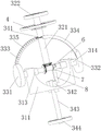
图6为本发明解压装置的其中一个视角的立体结构示意图;6 is a schematic three-dimensional structure diagram of one of the viewing angles of the decompression device of the present invention;
图7为本发明解压装置的另一个视角的立体结构示意图;7 is a schematic three-dimensional structural diagram of the decompression device of the present invention from another perspective;
图8为本发明球体的立体结构示意图;Fig. 8 is the three-dimensional structure schematic diagram of the sphere of the present invention;
图9为本发明球体的侧视图;Fig. 9 is the side view of the sphere of the present invention;
图10为图9沿C-C线的剖视图;FIG. 10 is a cross-sectional view along line C-C of FIG. 9;
图11为图9沿D-D线的剖视图;Fig. 11 is the sectional view along D-D line of Fig. 9;
图中:阀管组件1,第一阀管11,阀体12,阀座13,第二阀管14,球体2,凹槽21,通孔22,容纳槽23,避让孔24,第一弧形槽25,第二弧形槽26,齿轮槽27,解压装置3,先开组件31,U型块311,双向丝杆312,第一堵头313,第二堵头314,驱动组件32,转动杆321,第一转盘322,第一伞齿323,第二伞齿324,封闭组件33,第一封闭盘331,第二封闭盘332,第一弧形齿槽板333,第二弧形齿槽板334,第一齿槽335,第二齿槽336,转动组件34,齿轮341,导向杆342,丝杆343,第二转盘344,第三转盘4,旋转轴41,弧形凹槽5,限位圆环6,半圆环7,限位杆8。In the figure:
具体实施方式Detailed ways
下面结合附图和具体实施例对本发明作进一步的详细描述。The present invention will be further described in detail below with reference to the accompanying drawings and specific embodiments.
如图1至11所示,一种能够先行解压的水利控制球阀,包括阀管组件1,所述阀管组件1包括阀体12和与阀体12两端连通的第一阀管11和第二阀管14,所述阀体12内容纳有球体2和解压装置3,所述解压装置3包括设置在球体2内且能够预先解压的泄压机构和设置在球体2表面的封闭机构,所述球体2内开设有通孔22,所述第一阀管11和第二阀管14靠近阀体12的一端均安装有用于对球体2进行限位的阀座13。As shown in FIGS. 1 to 11 , a water conservancy control ball valve that can be decompressed in advance includes a
优选地,所述泄压机构包括可预先打开球体2的先开组件31和用于驱动先开组件31开闭的驱动组件32,所述封闭机构包括封闭组件33和用于驱动封闭组件33在球体2表面移动的转动组件34,所述先开组件31安装在球体2内,所述驱动组件32与先开组件31啮合,所述球体2表面开设有用于容纳封闭组件33的凹槽21,所述转动组件34与封闭组件33啮合。Preferably, the pressure relief mechanism includes a
优选地,所述先开组件31包括开设有弧面槽的U型块311、轴线垂直于通孔22中心轴线的双向丝杆312、与双向丝杆312两端螺纹配合的第一堵头313和第二堵头314,所述球体2内设置有用于容纳U型块311的容纳槽23,所述球体2和U型块311均开设有与第一堵头313和第二堵头314配合的避让孔24;所述驱动组件32包括有贯穿阀体12并插入通孔22内的转动杆321和安装在转动杆321一端的第一转盘322,所述转动杆321位于通孔22内的一端设置有第一伞齿323,双向丝杆312的中部安装有第二伞齿324和呈工字轮结构的限位圆环6,第一伞齿323与第二伞齿324啮合,限位圆环6的环形槽与半圆环7滑动配合,半圆环7通过限位杆8与U型块311固定连接。Preferably, the
优选地,所述第一堵头313和第二堵头314均为方形结构,所有避让孔24也均为方形孔。Preferably, the
优选地,所述封闭组件33包括有能够封闭避让孔24的第一封闭盘331和第二封闭盘332,所述第一封闭盘331上安装有第一弧形齿槽板333,所述通孔22的轴线垂直经过第一弧形齿槽板333所在平面的圆心,所述第二封闭盘332上安装有第二弧形齿槽板334,所述通孔22的轴线垂直经过第二弧形齿槽板334所在平面的圆心,所述第一封闭盘331和第二封闭盘332分别安装在位于双向丝杆312轴线两端的凹槽21内。Preferably, the
优选地,所述转动组件34包括有安装在转动杆321上的齿轮341,所述第一弧形齿槽板333沿着自身弧度方向等间距设置有若干个与齿轮341啮合的第一齿槽335,所述第二弧形齿槽板334沿着自身弧度方向等间距设置有若干个与齿轮341啮合的第二齿槽336,所述球体2设置有用于容纳第一弧形齿槽板333的第一弧形槽25和用于容纳第二弧形齿槽板334的第二弧形槽26。第一弧形槽25和第二弧形槽26能够方便齿轮341在旋转的时候,第一弧形齿槽板333和第二弧形齿槽板334沿着自身的弧度方向对向移动。Preferably, the
优选地,所述球体2内还设有与U型块311滑动配合的导向杆342,所述先开组件31包括有贯穿球体2并插入容纳槽23内的丝杆343,丝杆343一端与U型块311中部螺纹配合,丝杆343另一端与第二转盘344中心固定连接。Preferably, the
优选地,所述球体2的表面设置有弧形凹槽5,所述弧形凹槽5所在平面与转动杆321的轴线垂直。当避让孔24流通的时候,会卸掉一部分压力,然后转动球体2,由于弧形凹槽5与避让孔24之间流通,水流在转动球体2的同时持续流通,减小打开球阀的时间。Preferably, the surface of the
优选地,所述球体2包括有用于容纳齿轮341的齿轮槽27,第一弧形槽25通过齿轮槽27与第二弧形槽26互通。Preferably, the
优选地,所述球体2通过旋转轴41与阀体12转动配合,旋转轴41位于阀体12外侧的一端安装有第三转盘4。当解压装置3打开的时候,使得球阀两侧的压差减小了之后,旋转第三转盘4,使得球体2的通孔22旋转到与第一阀管11导通,从而将球阀完全打开。Preferably, the
本实施例工作原理如下:The working principle of this embodiment is as follows:
工作原理:当控制球阀处于关闭的状态下转为导通的状态,第一阀管11内的水压大于第二阀管14内的水压,使得旋转球体2的扭矩较大,工作人员难以打开,通过解压装置3缩小第一阀管11和第二阀管14的压差,转动第一转盘322,带动转动杆321旋转,使得齿轮341和第一伞齿323同步旋转,第一伞齿323旋转,使得第二伞齿324和双向丝杆312绕自身的中心线旋转,使得原本在球体避让孔24内的第一堵头313和第二堵头314对向朝球体2的球心移动,离开球体2的避让孔24且进入U型块311的避让孔24内,与此同时齿轮341顺时针旋转,与齿轮342啮合的第一弧形齿槽板333和第二弧形齿槽板334沿着自身的弧度方向对向移动,使得第一封闭盘331和第二封闭盘332沿着凹槽21的球面向靠近第一转盘322的一端对向移动,将球体2的避让孔24露出来,旋转第二转盘344,使得丝杆343正向旋转,与丝杆343螺纹配合的U型块311带动第一堵头313、第二堵头314和双向丝杆312一齐朝第二转盘344移动,U型块311与球体2的避让孔24错位,此时,第一伞齿323和第二伞齿324分离,使得球体2的两个避让孔24连通,从而第一阀管11和第二阀管14通过避让孔24连通,实现小股水流先行流动,使得第一阀管11和第二阀管14水压差减小,减小转动球体2的扭矩,即可较容易的旋转第三转盘4,带动球体2整体旋转,使得通孔22的轴线与第一阀管11和第二阀管14的轴线重合,从而球阀完全打开。Working principle: When the control ball valve is in a closed state and turns into a conducting state, the water pressure in the
当控制球阀处于导通的状态下转为关闭的状态时,旋转第三转盘4,带动球体2整体旋转,使得通孔22的轴线与第一阀管11和第二阀管14的轴线垂直,关闭球阀的主流道,然后旋转第二转盘344,使得丝杆343反向旋转,与丝杆343螺纹配合的U型块311带动第一堵头313、第二堵头314和双向丝杆312一齐朝第一转盘322移动,U型块311抵触到凹槽21靠近第一转盘322的端部,第一伞齿323和第二伞齿324啮合,此时U型块311的避让孔24正对球体2的避让孔24,反向转动第一转盘322,带动转动杆321旋转,使得齿轮341和第一伞齿323同步反向旋转,第一伞齿323反向旋转,使得第二伞齿324和双向丝杆312绕自身的中心线反向旋转,使得原本在U型块311的穿孔内的第一堵头313和第二堵头314背向移动,第一堵头313和第二堵头314分别进入球体2的避让孔24内,与此同时齿轮341逆时针旋转,与齿轮341啮合的第一弧形齿槽板333和第二弧形齿槽板334沿着自身的弧度方向背向移动,使得第一封闭盘331和第二封闭盘332沿着凹槽21的球面背向移动,第一封闭盘331和第二封闭盘332分别盖住对应的避让孔24,从而将球阀完全关闭。When the control ball valve is turned to the closed state from the ON state, the third turntable 4 is rotated to drive the ball 2 to rotate as a whole, so that the axis of the through hole 22 is perpendicular to the axes of the first valve tube 11 and the second valve tube 14, Close the main flow of the ball valve, and then rotate the second turntable 344, so that the screw 343 rotates in the opposite direction, and the U-shaped block 311 threaded with the screw 343 drives the first plug 313, the second plug 314 and the two-way screw 312 to align Moving toward the first turntable 322, the U-shaped block 311 abuts against the end of the groove 21 close to the first turntable 322, the first bevel teeth 323 and the second bevel teeth 324 mesh, and the escape hole 24 of the U-shaped block 311 is facing The avoidance hole 24 of the sphere 2 rotates the first turntable 322 in the reverse direction, and drives the rotation rod 321 to rotate, so that the gear 341 and the first bevel tooth 323 rotate in the opposite direction synchronously, and the first bevel tooth 323 rotates in the opposite direction, so that the second bevel tooth 324 And the two-way screw 312 rotates in the opposite direction around its center line, so that the first plug 313 and the second plug 314 originally in the perforation of the U-shaped block 311 move back, and the first plug 313 and the second plug 314 314 respectively enter the avoidance holes 24 of the sphere 2, and at the same time, the gear 341 rotates counterclockwise, and the first arc-shaped tooth slot plate 333 and the second arc-shaped tooth slot plate 334 meshing with the gear 341 face away from each other along their own radian direction. Move, so that the
上述的实施例仅为本发明的优选技术方案,而不应视为对于本发明的限制,本申请中的实施例及实施例中的特征在不冲突的情况下,可以相互任意组合。本发明的保护范围应以权利要求记载的技术方案,包括权利要求记载的技术方案中技术特征的等同替换方案为保护范围。即在此范围内的等同替换改进,也在本发明的保护范围之内。The above-mentioned embodiments are only the preferred technical solutions of the present invention, and should not be regarded as limitations of the present invention. The embodiments and features in the present application may be arbitrarily combined with each other without conflict. The protection scope of the present invention shall take the technical solutions described in the claims, including the equivalent alternatives of the technical features in the technical solutions described in the claims, as the protection scope. That is, equivalent replacements and improvements within this scope are also within the protection scope of the present invention.
Claims (8)
Priority Applications (1)
| Application Number | Priority Date | Filing Date | Title |
|---|---|---|---|
| CN201910080982.2A CN109681664B (en) | 2019-01-28 | 2019-01-28 | Hydraulic control ball valve capable of being decompressed in advance |
Applications Claiming Priority (1)
| Application Number | Priority Date | Filing Date | Title |
|---|---|---|---|
| CN201910080982.2A CN109681664B (en) | 2019-01-28 | 2019-01-28 | Hydraulic control ball valve capable of being decompressed in advance |
Publications (2)
| Publication Number | Publication Date |
|---|---|
| CN109681664A CN109681664A (en) | 2019-04-26 |
| CN109681664B true CN109681664B (en) | 2020-06-23 |
Family
ID=66194896
Family Applications (1)
| Application Number | Title | Priority Date | Filing Date |
|---|---|---|---|
| CN201910080982.2A Active CN109681664B (en) | 2019-01-28 | 2019-01-28 | Hydraulic control ball valve capable of being decompressed in advance |
Country Status (1)
| Country | Link |
|---|---|
| CN (1) | CN109681664B (en) |
Families Citing this family (2)
| Publication number | Priority date | Publication date | Assignee | Title |
|---|---|---|---|---|
| CN118728996B (en) * | 2024-09-02 | 2024-11-29 | 江苏派尔克制冷股份有限公司 | A double ball explosion-proof valve |
| CN119022089B (en) * | 2024-10-28 | 2025-01-21 | 浙江冠正阀门股份有限公司 | Bidirectional sealing frictionless track ball valve |
Citations (7)
| Publication number | Priority date | Publication date | Assignee | Title |
|---|---|---|---|---|
| FR561044A (en) * | 1923-03-28 | 1923-10-15 | Pipe valve | |
| US2330493A (en) * | 1942-06-12 | 1943-09-28 | Morgan Smith S Co | Tapered plug valve |
| GB969440A (en) * | 1962-06-11 | 1964-09-09 | Harold Edward Mcgowen | Orifice fluid valve assembly |
| CN102494151A (en) * | 2011-12-08 | 2012-06-13 | 杭州先锋电子技术股份有限公司 | Ball valve with pilot valve |
| CN205155231U (en) * | 2015-12-03 | 2016-04-13 | 科福龙阀门集团有限公司 | Pressure balance type fixes ball valve |
| CN108775413A (en) * | 2018-06-12 | 2018-11-09 | 安徽方程式工业设计服务有限公司 | A kind of ball valve for capableing of pressure release in advance |
| CN109099207A (en) * | 2018-10-10 | 2018-12-28 | 特阀江苏流体机械制造有限公司 | A kind of high-pressure and hydraulic ball valve easy to open |
-
2019
- 2019-01-28 CN CN201910080982.2A patent/CN109681664B/en active Active
Patent Citations (7)
| Publication number | Priority date | Publication date | Assignee | Title |
|---|---|---|---|---|
| FR561044A (en) * | 1923-03-28 | 1923-10-15 | Pipe valve | |
| US2330493A (en) * | 1942-06-12 | 1943-09-28 | Morgan Smith S Co | Tapered plug valve |
| GB969440A (en) * | 1962-06-11 | 1964-09-09 | Harold Edward Mcgowen | Orifice fluid valve assembly |
| CN102494151A (en) * | 2011-12-08 | 2012-06-13 | 杭州先锋电子技术股份有限公司 | Ball valve with pilot valve |
| CN205155231U (en) * | 2015-12-03 | 2016-04-13 | 科福龙阀门集团有限公司 | Pressure balance type fixes ball valve |
| CN108775413A (en) * | 2018-06-12 | 2018-11-09 | 安徽方程式工业设计服务有限公司 | A kind of ball valve for capableing of pressure release in advance |
| CN109099207A (en) * | 2018-10-10 | 2018-12-28 | 特阀江苏流体机械制造有限公司 | A kind of high-pressure and hydraulic ball valve easy to open |
Also Published As
| Publication number | Publication date |
|---|---|
| CN109681664A (en) | 2019-04-26 |
Similar Documents
| Publication | Publication Date | Title |
|---|---|---|
| CN109681664B (en) | Hydraulic control ball valve capable of being decompressed in advance | |
| US9022352B2 (en) | Hard seal plug valve | |
| US2956582A (en) | Valve | |
| US3367365A (en) | Valve | |
| CN110242770B (en) | Three-way ball valve | |
| KR100992084B1 (en) | Double-leaf disc movable ball valve | |
| CN101324279A (en) | Rotary Fluid Dispensing Valve | |
| RU159493U1 (en) | SHUT-OFF CONTROL BALL VALVE | |
| US3120944A (en) | Mechanical movement gate-valve having positive reduction means | |
| WO2016099337A1 (en) | Shutoff and control ball valve | |
| CN216279540U (en) | Multi-way control valve | |
| CN113757441B (en) | Hydraulic one-way valve | |
| CN215257918U (en) | Telescopic butterfly valve | |
| CN114017525A (en) | Control valve | |
| CN111365467B (en) | Flow control unit and anti-leakage valve | |
| CN214384191U (en) | Multichannel switching device and peristaltic pump | |
| CN114542727A (en) | An industrial butterfly valve | |
| CN210118517U (en) | Gear mechanism valve driving device | |
| CN216045564U (en) | Natural gas pressure valve device | |
| CN107830195B (en) | Pilot pressure relief type hydraulic ball valve | |
| CN216643139U (en) | A small ball valve controlled by lateral drive | |
| RU2357141C1 (en) | Double-circuit cock | |
| CN221723140U (en) | Manual pump valve block for hydraulic element | |
| CN112963570A (en) | Anti-scouring ball valve | |
| CN217683509U (en) | A kind of progressive adjustment special-shaped valve copper core |
Legal Events
| Date | Code | Title | Description |
|---|---|---|---|
| PB01 | Publication | ||
| PB01 | Publication | ||
| SE01 | Entry into force of request for substantive examination | ||
| SE01 | Entry into force of request for substantive examination | ||
| GR01 | Patent grant | ||
| GR01 | Patent grant |