[go: up one dir, main page]

CN109646791B - Kidney urine drainage system - Google Patents

Kidney urine drainage system Download PDF

Info

Publication number
CN109646791B
CN109646791B CN201811538751.3A CN201811538751A CN109646791B CN 109646791 B CN109646791 B CN 109646791B CN 201811538751 A CN201811538751 A CN 201811538751A CN 109646791 B CN109646791 B CN 109646791B
Authority
CN
China
Prior art keywords
urine
tube
storage box
analysis
crystal
Prior art date
Legal status (The legal status is an assumption and is not a legal conclusion. Google has not performed a legal analysis and makes no representation as to the accuracy of the status listed.)
Active
Application number
CN201811538751.3A
Other languages
Chinese (zh)
Other versions
CN109646791A (en
Inventor
王美豪
江海红
计玲晓
Current Assignee (The listed assignees may be inaccurate. Google has not performed a legal analysis and makes no representation or warranty as to the accuracy of the list.)
First Affiliated Hospital of Wenzhou Medical University
Original Assignee
First Affiliated Hospital of Wenzhou Medical University
Priority date (The priority date is an assumption and is not a legal conclusion. Google has not performed a legal analysis and makes no representation as to the accuracy of the date listed.)
Filing date
Publication date
Application filed by First Affiliated Hospital of Wenzhou Medical University filed Critical First Affiliated Hospital of Wenzhou Medical University
Priority to CN201811538751.3A priority Critical patent/CN109646791B/en
Publication of CN109646791A publication Critical patent/CN109646791A/en
Application granted granted Critical
Publication of CN109646791B publication Critical patent/CN109646791B/en
Active legal-status Critical Current
Anticipated expiration legal-status Critical

Links

Images

Classifications

    • AHUMAN NECESSITIES
    • A61MEDICAL OR VETERINARY SCIENCE; HYGIENE
    • A61MDEVICES FOR INTRODUCING MEDIA INTO, OR ONTO, THE BODY; DEVICES FOR TRANSDUCING BODY MEDIA OR FOR TAKING MEDIA FROM THE BODY; DEVICES FOR PRODUCING OR ENDING SLEEP OR STUPOR
    • A61M25/00Catheters; Hollow probes
    • A61M25/0017Catheters; Hollow probes specially adapted for long-term hygiene care, e.g. urethral or indwelling catheters to prevent infections
    • AHUMAN NECESSITIES
    • A61MEDICAL OR VETERINARY SCIENCE; HYGIENE
    • A61MDEVICES FOR INTRODUCING MEDIA INTO, OR ONTO, THE BODY; DEVICES FOR TRANSDUCING BODY MEDIA OR FOR TAKING MEDIA FROM THE BODY; DEVICES FOR PRODUCING OR ENDING SLEEP OR STUPOR
    • A61M31/00Devices for introducing or retaining media, e.g. remedies, in cavities of the body
    • A61M31/007Injectors for solid bodies, e.g. suppositories
    • AHUMAN NECESSITIES
    • A61MEDICAL OR VETERINARY SCIENCE; HYGIENE
    • A61MDEVICES FOR INTRODUCING MEDIA INTO, OR ONTO, THE BODY; DEVICES FOR TRANSDUCING BODY MEDIA OR FOR TAKING MEDIA FROM THE BODY; DEVICES FOR PRODUCING OR ENDING SLEEP OR STUPOR
    • A61M2202/00Special media to be introduced, removed or treated
    • A61M2202/04Liquids
    • A61M2202/0496Urine

Landscapes

  • Health & Medical Sciences (AREA)
  • Life Sciences & Earth Sciences (AREA)
  • General Health & Medical Sciences (AREA)
  • Public Health (AREA)
  • Heart & Thoracic Surgery (AREA)
  • Hematology (AREA)
  • Anesthesiology (AREA)
  • Animal Behavior & Ethology (AREA)
  • Engineering & Computer Science (AREA)
  • Biomedical Technology (AREA)
  • Veterinary Medicine (AREA)
  • Epidemiology (AREA)
  • Urology & Nephrology (AREA)
  • Biophysics (AREA)
  • Pulmonology (AREA)
  • Investigating Or Analysing Biological Materials (AREA)
  • External Artificial Organs (AREA)
  • Measurement Of The Respiration, Hearing Ability, Form, And Blood Characteristics Of Living Organisms (AREA)

Abstract

本发明公开了一种肾尿液引流系统,包括分析终端和双J管,所述双J管包括管体和固定在管体内壁上用于检测管体内尿液流速以及浓度的检测装置,所述检测装置与分析终端通过无线连接,所述分析终端包括尿液成分分析装置和分析服务器,所述检测装置和尿液成分分析装置均与分析服务器无线连接。本发明的肾尿液引流系统,通过分析终端和检测装置以及尿液成分分析装置的设置,便可有效的实现分析尿液的情况,进而实现了解肾和输尿管的功能检测效果。

Figure 201811538751

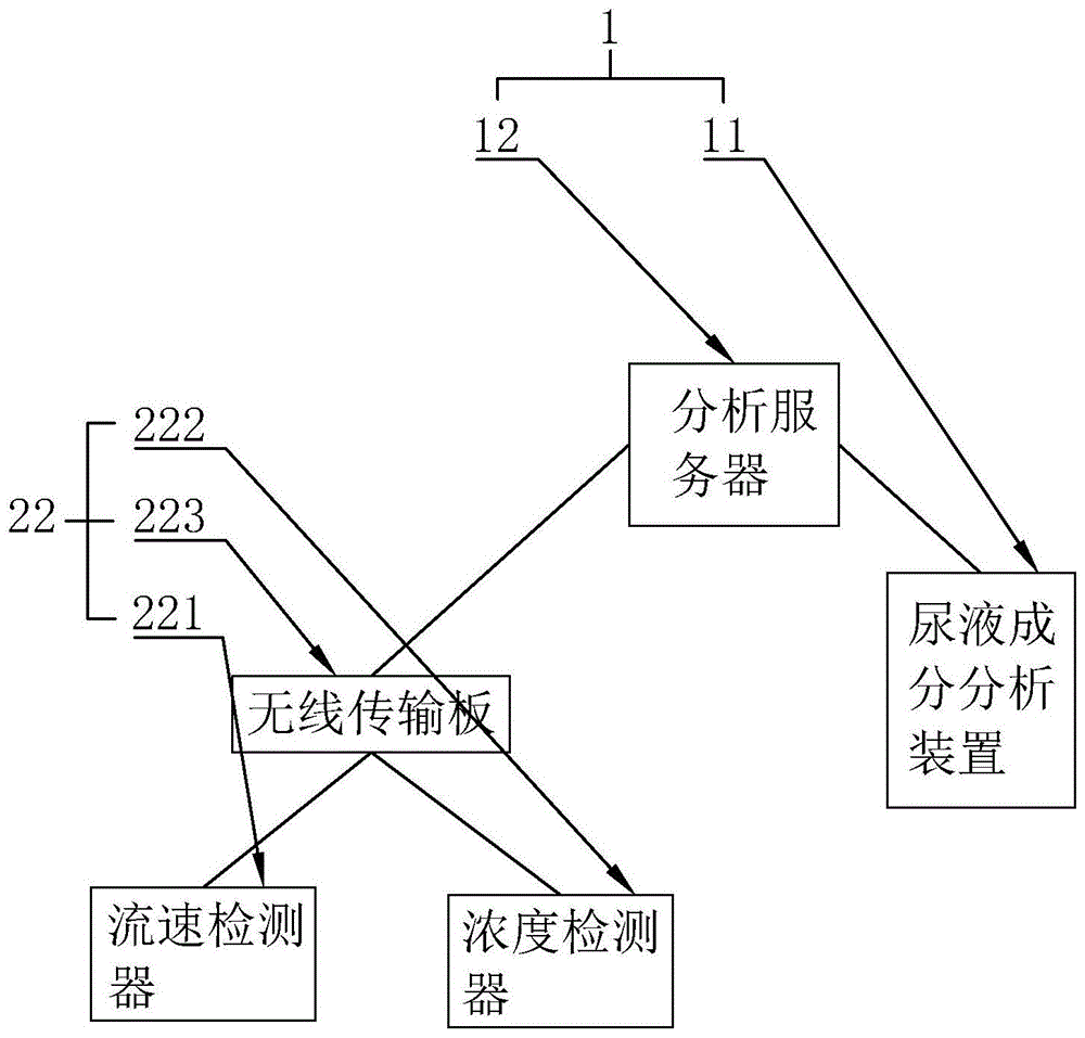
The invention discloses a renal urine drainage system, comprising an analysis terminal and a double J tube, wherein the double J tube includes a tube body and a detection device fixed on the inner wall of the tube for detecting the flow rate and concentration of urine in the tube. The detection device and the analysis terminal are wirelessly connected, and the analysis terminal includes a urine component analysis device and an analysis server, and both the detection device and the urine component analysis device are wirelessly connected to the analysis server. The renal urine drainage system of the present invention can effectively analyze the urine condition through the setting of the analysis terminal, the detection device and the urine component analysis device, thereby realizing the function detection effect of understanding the kidney and ureter.

Figure 201811538751

Description

Kidney urine drainage system
Technical Field
The invention relates to a medical system, in particular to a renal urine drainage system.
Background
The double J tube is the most commonly used drainage tube of the upper urinary tract, and has good internal drainage and support functions, so the double J tube is very commonly applied in urinary surgery, is often adopted when repairing ureteral injury or relieving stenosis of the upper urinary tract, and is even used for replacing the former T tube drainage by the conventional built-in double J tube in the ureterolithiasis or renal transplantation.
Except for the operation of the upper urinary tract, urine after double J tubes are implanted, certain complications are caused by the interaction between urothelium, and the early complications comprise discomfort, irritation of the shoulder skin, hematuria, urinary tract infection, fever and late complications of lumbago, such as hydronephrosis, double tube displacement, crusting, breakage and fracture. Meanwhile, when the double J-shaped tube is placed in a human body, the urinary salt deposition on the tube wall can be caused, the crusting of the attached tube can be formed, urinary infection, irritation symptoms of the shoulder skin, hematuria and the like are induced, serious patients cause ureteral obstruction, ipsilateral hydronephrosis, renal function damage and difficult tube drawing, even hospitalization operation treatment is needed, and the existing double J-shaped tube only comprises a tube body structure and cannot effectively detect the functions of the kidney and the ureter in the process of using the double J-shaped tube, so that the existing double J-shaped tube has the problem of insufficient functions.
Disclosure of Invention
Aiming at the defects in the prior art, the invention aims to provide a renal urine drainage system capable of effectively monitoring the functions of a kidney and a ureter.
In order to achieve the purpose, the invention provides the following technical scheme: a kidney urine drainage system comprises an analysis terminal and a double-J tube, wherein the double-J tube comprises a tube body and a detection device fixed on the inner wall of the tube body and used for detecting the urine flow rate and concentration in the tube body, the detection device and the analysis terminal are in wireless connection so as to output flow rate signals and concentration signals to the analysis terminal after detecting the urine flow rate and concentration, the analysis terminal comprises a urine component analysis device and an analysis server, the detection device and the urine component analysis device are both in wireless connection with the analysis server so as to input the flow rate signals and the concentration signals to the analysis server, the urine component analysis device comprises a urine storage box and a detection head arranged in the urine storage box, the urine storage box is attached and fixed on a position close to a urethral orifice, a urine collection device is arranged on the urine storage box, and the urine collection device is arranged on the urethral orifice, in order to gather urine storage box with urethral orifice discharge, detect head and analysis server wireless connection to in the analysis server is exported after detecting urine composition in the urine storage box.
Urine collection system includes the catheter and sets up the subassembly of urinating of adopting on the interior pipe wall of catheter, store up the urine box and fix on the catheter is for the position of adopting the urine subassembly to with the catheter intercommunication, it is used for gathering the urine and enters into storing up the urine box to adopt the urine subassembly, the one end of catheter is connected to patient's urethral orifice to this end is diffusion loudspeaker form, pastes the film at being equipped with silica gel of this end simultaneously, is used for pasting on patient's position that is close to the urethral orifice, with the tip lid that will pass through the catheter on the urethral orifice.
The urine collecting component comprises a urine collecting frame, a slidable power component arranged in the urine collecting frame and used for sealing the urine collecting frame to collect urine and a closed urine collecting plate arranged on the frame edge of the urine collecting frame, the urine collecting frame is fixed at the position where the urine collecting box is communicated with the urine passing tube to block or open the communication between the urine collecting box and the urine passing tube, the power component is linked with the urine collecting plate to drive the urine collecting plate to slide to seal or collect the urine, the power component is a strip-shaped power plate, one end of the power plate is elastically hinged with the frame edge of the urine collecting frame, the other end of the power plate extends into the urine passing tube, a rack is arranged on the plate edge of the urine collecting plate, a gear is coaxially fixed on the power plate hinged with the urine collecting frame, the gear is meshed with the rack, when urine passes through the urine passing tube, part of urine enters the urine collecting box through the opened urine collecting frame, and the power plate turns downwards, the gear drives the rack to further drive the urine collecting plate to ascend and close the urine collecting frame, wherein the elastic hinge joint of the power plate is in a force storage state.
As a further improvement of the invention, the detection device comprises a flow velocity detector, a concentration detector and a wireless transmission plate, wherein the flow velocity detector and the concentration detector are attached to the inner wall of the pipe body, the wireless transmission plate is coupled with the analysis server, and the flow velocity detector and the concentration detector are both in wireless connection with the wireless transmission plate so as to output flow velocity signals and concentration signals and then input the signals into the analysis server through the wireless transmission plate.
As a further improvement of the present invention, the flow velocity detector includes a pressure sensing crystal and a transmission crystal, the transmission crystal is fixed on the inner wall of the tube, the pressure sensing crystal is fixed on the side of the transmission crystal opposite to the inner wall of the tube, the pressure sensing crystal has a pressure sensing surface, the pressure sensing surface is arranged on the side of the pressure sensing crystal opposite to the transmission crystal, the pressure sensing crystal is coupled with the transmission crystal to sense pressure and output a pressure signal to the transmission crystal, the transmission crystal is connected with the wireless transmission board to transmit the pressure signal to the analysis server, and the analysis server analyzes and calculates a flow velocity value.
As a further improvement of the present invention, the concentration detector comprises a light emitting lamp and a light sensor disposed on the pressure sensing surface of the pressure sensing crystal, and the light sensor is coupled to the transmission crystal and is configured to output a light sensing signal to the transmission crystal for transmission to the analysis server through the transmission crystal.
The invention has the advantages that the kidney and the bladder of a patient can be effectively connected through the arrangement of the double J-shaped tubes, the urine drainage of the patient can be realized, the work of the ureter is assisted, the urine drainage can be effectively realized through the tube body by arranging the double J-shaped tubes into the tube body and the detection device, the flow rate and the concentration of the urine are detected through the detection device, the analysis terminal is arranged into the analysis and analysis server and the urine component analysis device, the detected flow rate, the concentration and the components of the urine can be further analyzed through the analysis server, the working states of the kidney and the ureter of the patient at the moment can be effectively judged, the urine can be effectively collected into the urine storage box through the arrangement of the urine collection device, the urine can be detected through the detection head, and when the person urinates, the urine at this moment is collected and the urine components are analyzed, and then the flow rate and the concentration of the urine detected by the detection device before urination are matched for analysis, so that the working states of the ureter and the kidney in each urination time period are analyzed, and the functions of the kidney and the ureter are effectively monitored.
Drawings
FIG. 1 is a block diagram of the modules of the drainage system of the present invention;
FIG. 2 is an overall structural view of a double J-tube;
FIG. 3 is an overall configuration view of a urine component analyzing apparatus;
fig. 4 is an enlarged view of a portion a in fig. 2.
Detailed Description
The invention will be further described in detail with reference to the following examples, which are given in the accompanying drawings.
Referring to fig. 1 to 4, the kidney urine drainage system of the present embodiment includes an analysis terminal 1 and a double J-tube 2, the double J-tube 2 includes a tube 21 and a detection device 22 fixed on an inner wall of the tube 21 for detecting a flow rate and a concentration of urine in the tube 21, the detection device 22 is wirelessly connected to the analysis terminal 1 for outputting a flow rate signal and a concentration signal to the analysis terminal 1 after detecting the flow rate and the concentration of urine, the analysis terminal 1 includes a urine component analysis device 11 and an analysis server 12, the detection device 22 and the urine component analysis device 11 are both wirelessly connected to the analysis server 12 for inputting the flow rate signal and the concentration signal to the analysis server 12, the urine component analysis device 11 includes a urine storage box 112 and a detection head 113 disposed in the urine storage box 112, the urine storage box 112 is attached and fixed at a position close to a urethral orifice, the urine storage box 112 is provided with the urine collection device 3, the urine collection device 3 is arranged on the urethral orifice to collect urine discharged from the urethral orifice into the urine storage box 112, the detection head 113 is in wireless connection with the analysis server 12 to detect urine components in the urine storage box 112 and then output the urine components into the analysis server 12, in the process of using the drainage system of the embodiment, only the double J tube 2 is required to be put into a patient, then the inside of the tube body 21 of the double J tube can be circulated, meanwhile, the detection device 22 in the tube body 21 can detect the flow rate and concentration of the urine circulated in the tube body 21 in real time and then transmit the urine to the analysis server 12 in a wireless transmission mode, meanwhile, after the patient urinates, the urine component analysis device 11 collects a part of urine by the urine collection device 3 into the urine storage box 112, and then through the arrangement of the detection head 113 in the urine storage box 112, the components of the urine in the urine storage box 112 can be effectively detected, so that the effect of detecting the components of the urine in the analysis server 12 is realized, then the functional states of the kidney and the ureter are finally obtained through the analysis of the analysis server 12, the effect of monitoring the functional states of the kidney and the ureter is effectively realized, meanwhile, because the detection head 113 needs to be immersed in the urine for a period of time for detecting the components of the urine, the detection head 113 can effectively realize the collection of a part of the urine in the urine storage box 112 for the detection of the detection head 113 through the arrangement of the urine collecting device 3, compared with the mode of directly arranging the detection head 113 in the tube body 21, the detection head 113 can have sufficient immersion time, and the accuracy of the detection data of the detection head 113 is increased, wherein the detection head 113 of the embodiment is the detection head of the urine analyzer in the prior art, and therefore no further description is given, and as for the analysis method in the, the analysis can be performed by using the medical knowledge of the relevance of the known urine parameters to the functions of the ureter and the kidney, wherein the tube wall of the tube body 21 in the embodiment can be set to be a sandwich structure, the anti-inflammatory drug is arranged in the sandwich structure, and then a plurality of through holes are formed in the inner wall of the sandwich structure at the same time, so that when the urine flows through the tube body 21, the urine contacts with the anti-inflammatory drug and then melts the anti-inflammatory drug, the urine has an anti-inflammatory effect, and the problem of inflammation caused by the implantation of the double J-tube 2 is avoided.
As a modified embodiment, the urine collecting device 3 comprises a urine passing tube 31 and a urine collecting component 32 disposed on the inner tube wall of the urine passing tube 31, the urine storage box 112 is fixed on the position of the urine passing tube 31 relative to the urine collecting component 32 and is communicated with the urine passing tube 31, the urine collecting component 32 is used for collecting urine into the urine storage box 112, one end of the urine passing tube 31 is connected to the urethral orifice of a patient and is in a diffusion trumpet shape, and a silica gel adhesive film is disposed at the end for adhering the end of the urine passing tube 31 to the position close to the urethral orifice of the patient so as to cover the end of the urine passing tube 31 on the urethral orifice, when the urine collecting device 3 collects urine, one end of the urine passing tube 31 is disposed on the urethral orifice of the patient and is adhered on the urination organ of the patient through the silica gel adhesive film, and then completely covers the urethral orifice of the patient through the diffusion trumpet shape thereof, the problem that urine leaks when a patient urinates is avoided, so that during the urination of the patient, the urine is discharged to the outside through the urine passing pipe 31, and then partial urine collection is performed through the urine collecting component 32 during the urination, so that the urine component, the urine flow rate and the urine concentration in a urination time period can be detected in cooperation with the detection device 22, so that the analysis server 12 can effectively analyze the ureter and the functional state of the kidney of the patient in the urination time period based on the data, and an effect of monitoring the kidney and the functional state of the ureter of the patient is effectively realized.
As an improved specific embodiment, the urine collection assembly 32 includes a urine collection frame 321, a urine collection plate 322 slidably disposed in the urine collection frame 321 for closing and opening the urine collection frame 321, and a power member 323 disposed on a frame edge of the urine collection frame 321, the urine collection frame 321 is fixed at a position where the urine storage box 112 communicates with the urine drainage tube 31 to block or open communication between the urine storage box 112 and the urine drainage tube 31, the power member 323 is linked with the urine collection plate 322 to drive the urine collection plate 322 to slidably close or collect the urine collection frame 321, the power member 323 is a strip-shaped power plate, one end of the power plate is elastically hinged to the frame edge of the urine collection frame 321, the other end of the power plate extends into the urine drainage tube 31, a plate edge of the urine collection plate 322 is provided with a rack, a hinge shaft of the power plate and the urine collection frame 321 is coaxially fixed with a gear, the gear is engaged with the rack, when urine passes through the urine drainage tube 31, part of urine enters the urine storage box 112 through the opened urine collection frame 321, the power plate is turned downwards, the gear drives the rack to drive the urine collection plate 322 to ascend to close the urine collection frame 321, wherein the elastic hinge of the power plate is in a force accumulation state, the urine collection plate 322 is closed to the urine collection frame 321 through the arrangement of the urine collection frame 321, urine is discharged from top to bottom as shown in figure 3, part of urine firstly enters the urine storage box 112, then the urine impacts the power plate through the urine, the power plate is turned downwards, then the urine collection plate 322 is moved upwards to close the urine collection frame 321 through the matching action of the gear and the rack, and the problem that the detection of the detection head 113 is influenced by the continuous entering of the subsequent urine into the urine storage box 112 is solved, the urine storage box 112 of this embodiment may be made of an extrudable material, such as a silicone or a rubber material, after the detection of the detection head 113 is completed, and at the same time, the power plate is reset due to the elastic hinge to drive the urine collection plate 322 to collect the urine collection frame 321, the patient may extrude the urine collected in the urine storage box 112 into the urine tube 31 by extruding the urine storage box 112, so as to empty the urine in the urine storage box 112 for further urine collection when the urine is collected next time, or may set a urine discharge tube communicating with the urine storage box 112 at a position below the urine collection frame 321, and the urine discharge tube is provided with a valve linked with the urine collection plate 322, so that when the urine collection plate 322 hits the urine collection frame 321, the valve is opened to discharge the urine in the urine storage box 112, wherein in this embodiment, the urine collection plate 322 may be set into an upper portion and a lower portion, the urine collecting frame 321 is arranged to be of a structure in a shape like a Chinese character 'ri', the power component 323 is arranged on a middle cross of the structure in the shape like the Chinese character 'ri', the side edges of the two parts are provided with racks, and are meshed with the two side edges of the gear relatively to realize relative movement, so when the urine collecting plate 322 slides downwards to collect the urine collecting frame 321 on the upper surface, the urine collecting plate 322 on the lower surface slides upwards to open the urine drainage tube, the urine drainage tube is opened, and the urine in the corresponding urine storage box 112 flows into the urine drainage tube 31 along with the urine drainage tube, so that the effect of draining the urine in the urine storage box 112 is realized.
As a modified embodiment, the detecting device 22 includes a flow rate detector 221 and a concentration detector 222 attached to the inner wall of the tube 21, and a wireless transmission board 223, the wireless transmission board 223 is coupled to the analysis server 12, the flow rate detector 221 and the concentration detector 222 are both wirelessly connected to the wireless transmission board 223, and output flow rate signals and concentration signals are input into the analysis server 12 through the wireless transmission board 223, by the arrangement of the flow rate detector 221, urine flow rate can be effectively detected, by the concentration detector 222, urine concentration can be effectively detected, by the arrangement of the wireless transmission board 223, by wirelessly connecting with the analysis server 12, flow rate signals and concentration signals can be effectively transmitted into the analysis server 12, and the flow rate of urine can well embody the function of the ureter, the concentration of the urine can be well matched with the components of the urine to show the function of the kidney, so that the monitoring of the functions of the ureter and the kidney can be effectively realized by detecting the two parameters.
As a modified specific embodiment, the flow rate detector 221 includes a pressure sensing crystal 2211 and a transmission crystal 2212, the transmission crystal 2212 is fixed on the inner wall of the tube 21, the pressure sensing crystal 2211 is fixed on the side of the transmission crystal 2212 opposite to the inner wall of the tube 21, the pressure sensing crystal 2211 has a pressure sensing surface, the pressure sensing surface is arranged on the side of the pressure sensing crystal 2211 opposite to the transmission crystal 2212, the pressure sensing crystal 2211 is coupled with the transmission crystal 2212 to sense the pressure and output a pressure signal to the transmission crystal 2212, the transmission crystal 2212 is connected with a wireless transmission board 223 to transmit the pressure signal to the analysis server 12 for analysis and calculation by the analysis server 12, and the flow rate value is obtained because if the urine is provided with an obstruction in the flow path during the flow, the pressure exerted on the obstruction by the urine is proportional to the flow rate, therefore, feel the mode that the urine applied to the pressure on the response face through pressure sensing crystal 2211, so just can be fine the realization detect the effect of urine velocity of flow, simultaneously through pressure sensing crystal 2211 and transmission crystal 2212's setting, alright effectual increase body 21's density, and then realized that the development that two J pipes can be better has imaged.
As an improved specific embodiment, the concentration detector 222 includes a light emitting lamp 4 and a light sensor 5 disposed on the pressure sensing surface of the pressure sensing crystal 2211, and the light sensor 5 is coupled to the transmission crystal 2212 and is configured to output a light sensing signal to the transmission crystal 2212 and further to be transmitted to the analysis server 12 through the transmission crystal 2212, since urine is in a liquid state, the urine has a certain light transmittance for light, especially when the urine concentration is higher, the light transmittance of urine is lower, and the corresponding reflectivity is higher, so that in this embodiment, the light emitting lamp 4 is adopted to emit light with a certain brightness, and then the urine concentration is detected by how much urine is reflected, the whole structure is simple and easy to implement, wherein the light sensor 5 of this embodiment may adopt a photoresistor, and the change of the output resistance is utilized to reflect the light of urine, further reflecting the concentration of urine.
In summary, the renal urine drainage system of the present embodiment detects three parameters, namely, the flow rate, the concentration and the composition of urine, by means of the cooperation between the detection device 22 and the urine composition analysis device 11 in the double J-tube 2 and the external analysis server 12, so as to monitor the ureter and the kidney of the patient.
The above description is only a preferred embodiment of the present invention, and the protection scope of the present invention is not limited to the above embodiments, and all technical solutions belonging to the idea of the present invention belong to the protection scope of the present invention. It should be noted that modifications and embellishments within the scope of the invention may occur to those skilled in the art without departing from the principle of the invention, and are considered to be within the scope of the invention.

Claims (4)

1.一种肾尿液引流系统,其特征在于:包括分析终端(1)和双J管(2),所述双J管(2)包括管体(21)和固定在管体(21)内壁上用于检测管体(21)内尿液流速以及浓度的检测装置(22),所述检测装置(22)与分析终端(1)通过无线连接,以检测尿液流速以及浓度后输出流速信号和浓度信号至分析终端(1)内,所述分析终端(1)包括尿液成分分析装置(11)和分析服务器(12),所述检测装置(22)和尿液成分分析装置(11)均与分析服务器(12)无线连接,以输入流速信号和浓度信号至分析服务器(12)内,所述尿液成分分析装置(11)包括储尿盒(112)和设置在储尿盒(112)内的检测头(113),所述储尿盒(112)贴合固定在靠近尿道口的位置上,所述储尿盒(112)上设有尿液采集装置(3),所述尿液采集装置(3)设置在尿道口上,以将尿道口排出的尿液采集到储尿盒(112)内,所述检测头(113)与分析服务器(12)无线连接,以检测储尿盒(112)内尿液成分后输出到分析服务器(12)内,所述尿液采集装置(3)包括通尿管(31)和设置在通尿管(31)的内管壁上的采尿组件(32),所述储尿盒(112)固定在通尿管(31)相对于采尿组件(32)的位置上,并与通尿管(31)连通,所述采尿组件(32)用于采集尿液进入到储尿盒(112)内,所述通尿管(31)的一端连接至病人尿道口,并且该端呈扩散喇叭状,同时在该端的设有硅胶粘贴薄膜,用于粘贴到病人靠近尿道口的位置上,以将通尿管(31)的端部盖在尿道口上,所述采尿组件(32)包括采尿框(321)、可滑移的设置在采尿框(321)内用于封闭打开采尿框(321)采尿板(322)和设置在采尿框(321)的框边上的动力构件(323),所述采尿框(321)固定在储尿盒(112)与通尿管(31)相连通的位置上,以阻断或是打开储尿盒(112)与通尿管(31)之间的连通,所述动力构件(323)与采尿板(322)联动,以驱动采尿板(322)滑移封闭或是打开采尿框(321),所述动力构件(323)为呈长条状的动力板,该动力板的一端与采尿框(321)的框边弹性铰接,另一端伸入到通尿管(31)内,所述采尿板(322)的板边设有齿条,所述动力板与采尿框(321)铰接的铰接轴上同轴固定有齿轮,所述齿轮与齿条相啮合,当尿液从通尿管(31)内通过时,部分尿液通过打开的采尿框(321)进入到储尿盒(112)内,同时动力板向下翻转,齿轮带动齿条进而带动采尿板(322)上升封闭采尿框(321),其中,动力板的弹性铰接处于蓄力状态。1. a renal urine drainage system is characterized in that: comprise analysis terminal (1) and double J pipe (2), and described double J pipe (2) comprises pipe body (21) and is fixed on pipe body (21) A detection device (22) on the inner wall for detecting the urine flow rate and concentration in the tube body (21), the detection device (22) is wirelessly connected to the analysis terminal (1) to detect the urine flow rate and the concentration and then output the flow rate The signal and the concentration signal are sent to an analysis terminal (1), the analysis terminal (1) includes a urine component analysis device (11) and an analysis server (12), the detection device (22) and the urine component analysis device (11) ) are wirelessly connected with the analysis server (12) to input the flow rate signal and the concentration signal into the analysis server (12), the urine component analysis device (11) comprises a urine storage box (112) and a urine storage box (112) and a urine storage box ( 112) in the detection head (113), the urine storage box (112) is fitted and fixed at a position close to the urethral opening, the urine storage box (112) is provided with a urine collection device (3), the The urine collection device (3) is arranged on the urethral opening to collect urine discharged from the urethral opening into the urine storage box (112), and the detection head (113) is wirelessly connected with the analysis server (12) to detect the stored urine The urine components in the box (112) are then output to the analysis server (12), and the urine collection device (3) includes a urine-passing tube (31) and a collection device disposed on the inner tube wall of the urine-passing tube (31). Urine assembly (32), the urine storage box (112) is fixed on the position of the urine collection tube (31) relative to the urine collection assembly (32), and communicated with the urine collection pipe (31), and the urine collection assembly ( 32) For collecting urine into the urine storage box (112), one end of the urethral tube (31) is connected to the patient's urethra, and the end is in the shape of a diffuser horn, and a silicone adhesive film is provided at the end. , used for sticking to the position of the patient close to the urethral orifice, to cover the end of the urethral tube (31) on the urethral orifice, the urine sampling assembly (32) includes a urine sampling frame (321), a sliding set In the urine collection frame (321), it is used to close and open the urine collection frame (321), the urine collection plate (322), and the power member (323) arranged on the frame edge of the urine collection frame (321). The urine collection frame (321) 321) is fixed at the position where the urine storage box (112) is communicated with the urinary conduit (31) to block or open the communication between the urine storage box (112) and the urinary conduit (31). The component (323) is linked with the urine collection board (322) to drive the urine collection board (322) to slide to close or open the urine collection frame (321). One end of the power plate is elastically hinged with the frame edge of the urine sampling frame (321), and the other end extends into the urine pipe (31). A gear is coaxially fixed on the hinge shaft where the plate is hinged with the urine collection frame (321), and the gear is meshed with the rack. Box (321 ) into the urine storage box (112), at the same time the power plate is turned downward, the gear drives the rack and then drives the urine collection plate (322) to rise to close the urine collection frame (321), wherein the elastic hinge of the power plate is in a state of accumulating force . 2.根据权利要求1所述的肾尿液引流系统,其特征在于:所述检测装置(22)包括贴附设置在管体(21)内壁上的流速检测器(221)和浓度检测器(222)以及无线传输板(223),所述无线传输板(223)与分析服务器(12)耦接,所述流速检测器(221)和浓度检测器(222)均与无线传输板(223)无线连接,以输出流速信号和浓度信号后通过无线传输板(223)输入到分析服务器(12)内。2. The renal urine drainage system according to claim 1, wherein the detection device (22) comprises a flow rate detector (221) and a concentration detector (221) attached to the inner wall of the pipe body (21). 222) and a wireless transmission board (223), the wireless transmission board (223) is coupled to the analysis server (12), the flow rate detector (221) and the concentration detector (222) are both connected to the wireless transmission board (223) After being connected wirelessly, the flow rate signal and the concentration signal are outputted and then input into the analysis server (12) through the wireless transmission board (223). 3.根据权利要求2所述的肾尿液引流系统,其特征在于:所述流速检测器(221)包括感压晶体(2211)和传输晶体(2212),所述传输晶体(2212)固定在管体(21)的内壁上,所述感压晶体(2211)固定在传输晶体(2212)背向管体(21)内壁的一侧上,所述感压晶体(2211)上具有感压面,该感压面设置在感压晶体(2211)背向传输晶体(2212)的一侧上,所述感压晶体(2211)与传输晶体(2212)耦接,以感受压力后输出压力信号至传输晶体(2212)内,所述传输晶体(2212)与无线传输板(223)连接,以传输压力信号至分析服务器(12)内,进而通过分析服务器(12)分析计算得出流速数值。3. The renal urine drainage system according to claim 2, wherein the flow rate detector (221) comprises a pressure-sensitive crystal (2211) and a transmission crystal (2212), and the transmission crystal (2212) is fixed on the On the inner wall of the tube body (21), the pressure-sensitive crystal (2211) is fixed on the side of the transmission crystal (2212) facing away from the inner wall of the tube body (21), and the pressure-sensitive crystal (2211) has a pressure-sensitive surface , the pressure-sensitive surface is arranged on the side of the pressure-sensitive crystal (2211) facing away from the transmission crystal (2212). In the transmission crystal (2212), the transmission crystal (2212) is connected with the wireless transmission board (223) to transmit the pressure signal to the analysis server (12), and then the flow rate value is obtained through analysis and calculation by the analysis server (12). 4.根据权利要求3所述的肾尿液引流系统,其特征在于:所述浓度检测器(222)包括设置在感压晶体(2211)的感压面上的发光灯(4)和光感应器(5),所述光感应器(5)与传输晶体(2212)耦接,用于输出光感信号至传输晶体(2212) 内,进而通过传输晶体(2212)传输到分析服务器(12)内。4. The renal urine drainage system according to claim 3, wherein the concentration detector (222) comprises a light-emitting lamp (4) and a light sensor arranged on the pressure-sensitive surface of the pressure-sensitive crystal (2211) (5), the light sensor (5) is coupled with the transmission crystal (2212), and is used for outputting the light sensing signal to the transmission crystal (2212), and then transmits the signal to the analysis server (12) through the transmission crystal (2212) .
CN201811538751.3A 2018-12-14 2018-12-14 Kidney urine drainage system Active CN109646791B (en)

Priority Applications (1)

Application Number Priority Date Filing Date Title
CN201811538751.3A CN109646791B (en) 2018-12-14 2018-12-14 Kidney urine drainage system

Applications Claiming Priority (1)

Application Number Priority Date Filing Date Title
CN201811538751.3A CN109646791B (en) 2018-12-14 2018-12-14 Kidney urine drainage system

Publications (2)

Publication Number Publication Date
CN109646791A CN109646791A (en) 2019-04-19
CN109646791B true CN109646791B (en) 2021-04-13

Family

ID=66114680

Family Applications (1)

Application Number Title Priority Date Filing Date
CN201811538751.3A Active CN109646791B (en) 2018-12-14 2018-12-14 Kidney urine drainage system

Country Status (1)

Country Link
CN (1) CN109646791B (en)

Citations (3)

* Cited by examiner, † Cited by third party
Publication number Priority date Publication date Assignee Title
WO2016151595A1 (en) * 2015-03-26 2016-09-29 Vensica Medical Ltd. Ultrasonic urinary bladder drug delivery
CN206990276U (en) * 2017-07-30 2018-02-09 刘慧萍 A kind of urine sampling device for cryptorrhea detection
CN107874789A (en) * 2017-12-26 2018-04-06 东莞市智配机电科技有限公司 Urine collection system for gynaecology and obstetrics

Family Cites Families (11)

* Cited by examiner, † Cited by third party
Publication number Priority date Publication date Assignee Title
DE2357062C2 (en) * 1973-11-15 1982-07-01 Ulrich Walter, Maschinenbau GmbH, 4006 Erkrath Method and device for taking a sample from a conveying line
CN85200016U (en) * 1985-04-01 1985-09-10 清华大学 Silicon pieroresistance probe for measuring the velocity of pulsating flow
US5720054A (en) * 1993-12-30 1998-02-24 Toto Ltd. Method and apparatus for sampling urine
EP4233696A3 (en) * 2014-09-28 2023-09-06 Potrero Medical, Inc. Systems, devices and methods for sensing physiologic data and draining and analyzing bodily fluids
CN204395066U (en) * 2014-11-07 2015-06-17 南通市妇幼保健院 A kind of urinary catheter indwelling device controlling urinary function
US11376151B2 (en) * 2014-11-13 2022-07-05 Maurice Marcel Garcia Gravity independent medical drainage systems
CN204882160U (en) * 2015-08-14 2015-12-16 郝英丽 Inspection is with novel urine ware that connects
CN204972666U (en) * 2015-09-30 2016-01-20 成都漫程科技有限公司 Area is intelligent monitoring, accuse urine device and system of monitoring of urinary tract urine hydromechanics down
CN207928336U (en) * 2017-05-23 2018-10-02 张秀芳 A kind of inspection urine collector
CN206832526U (en) * 2017-06-06 2018-01-02 丁妹 One kind is convenient to be taken out and is applied to different size urine sample apparatus for placing
CN207488300U (en) * 2017-11-28 2018-06-12 郑春生 A kind of division of endocrinology's urine sugar detection device

Patent Citations (3)

* Cited by examiner, † Cited by third party
Publication number Priority date Publication date Assignee Title
WO2016151595A1 (en) * 2015-03-26 2016-09-29 Vensica Medical Ltd. Ultrasonic urinary bladder drug delivery
CN206990276U (en) * 2017-07-30 2018-02-09 刘慧萍 A kind of urine sampling device for cryptorrhea detection
CN107874789A (en) * 2017-12-26 2018-04-06 东莞市智配机电科技有限公司 Urine collection system for gynaecology and obstetrics

Also Published As

Publication number Publication date
CN109646791A (en) 2019-04-19

Similar Documents

Publication Publication Date Title
US20190357837A1 (en) Urodynamic monitoring system and drainage monitoring control unit thereof
JP2019512672A (en) Automatic Urine Collector-Analyzer
JP2019536510A (en) Diagnostic drainage catheter assembly and method of diagnostic drainage
US20080188770A1 (en) Device and Method for the Collection of a Urine Sample
CN103301514A (en) Multifunctional indwelling urethral catheterization device
CN205360074U (en) Automatic urethral catheterization device of pressure detection
CN105484331B (en) The urine Dynamic testing intelligent closestool and health services system of a kind of household
CN203263900U (en) Multifunctional retention catheterization device
CN106421956A (en) Bladder irrigation and drainage control device
CN103908706A (en) Automatic urinary catheterization system
WO2017045513A1 (en) Urinary catheter with automatic pressure relief function
CN105148382A (en) Intelligentized monitoring and urine-controlling device and system having function of lower urinary tract urodynamics monitoring
CN109646791B (en) Kidney urine drainage system
CN111494728B (en) A nephroureterostomy urine diversion monitoring system
CN216394064U (en) Bladder pressure monitoring and automatic opening device
CN212261996U (en) Urine drainage control and urine volume measurement system
WO2025090837A1 (en) Bodily fluid management system
CN211486133U (en) A urinary catheter with a pressure sensor
CN106344979A (en) Drainage pipeline with pressure sensor
CN118266929A (en) Urine volume monitoring system
CN201067513Y (en) Disposable precision quantity measurement urine bag
CN211094287U (en) Urine sampling device for nursing urine examination
CN117018331A (en) An intelligent bladder flushing early warning monitoring and control system
CN222398392U (en) Dynamic cystometry device
CN211834414U (en) Blood sampling structure of artery catheterization

Legal Events

Date Code Title Description
PB01 Publication
PB01 Publication
SE01 Entry into force of request for substantive examination
CB03 Change of inventor or designer information

Inventor after: Wang Meihao

Inventor after: Jiang Haihong

Inventor after: Ji Lingxiao

Inventor before: Jiang Haihong

Inventor before: Ji Lingxiao

Inventor before: Wang Meihao

CB03 Change of inventor or designer information
TA01 Transfer of patent application right

Effective date of registration: 20200804

Address after: 325035 Shangcai village, nanbaixiang street, Ouhai District, Wenzhou City, Zhejiang Province

Applicant after: THE FIRST AFFILIATED HOSPITAL OF WENZHOU MEDICAL University

Address before: 325035 Wenzhou National University Science Park, No. 38 Dongfangnan Road, Ouhai Economic Development Zone, Wenzhou City, Zhejiang Province

Applicant before: WENZHOU MEDICAL University

TA01 Transfer of patent application right
GR01 Patent grant
GR01 Patent grant