CN109562259B - Cochlear implant comprising electrode array and method for manufacturing electrode array - Google Patents
Cochlear implant comprising electrode array and method for manufacturing electrode array Download PDFInfo
- Publication number
- CN109562259B CN109562259B CN201680088333.1A CN201680088333A CN109562259B CN 109562259 B CN109562259 B CN 109562259B CN 201680088333 A CN201680088333 A CN 201680088333A CN 109562259 B CN109562259 B CN 109562259B
- Authority
- CN
- China
- Prior art keywords
- workpiece
- flexible body
- electrode array
- contacts
- mold member
- Prior art date
- Legal status (The legal status is an assumption and is not a legal conclusion. Google has not performed a legal analysis and makes no representation as to the accuracy of the status listed.)
- Active
Links
Images


Classifications
-
- A—HUMAN NECESSITIES
- A61—MEDICAL OR VETERINARY SCIENCE; HYGIENE
- A61N—ELECTROTHERAPY; MAGNETOTHERAPY; RADIATION THERAPY; ULTRASOUND THERAPY
- A61N1/00—Electrotherapy; Circuits therefor
- A61N1/18—Applying electric currents by contact electrodes
- A61N1/32—Applying electric currents by contact electrodes alternating or intermittent currents
- A61N1/36—Applying electric currents by contact electrodes alternating or intermittent currents for stimulation
- A61N1/36036—Applying electric currents by contact electrodes alternating or intermittent currents for stimulation of the outer, middle or inner ear
- A61N1/36038—Cochlear stimulation
-
- A—HUMAN NECESSITIES
- A61—MEDICAL OR VETERINARY SCIENCE; HYGIENE
- A61N—ELECTROTHERAPY; MAGNETOTHERAPY; RADIATION THERAPY; ULTRASOUND THERAPY
- A61N1/00—Electrotherapy; Circuits therefor
- A61N1/02—Details
- A61N1/04—Electrodes
- A61N1/05—Electrodes for implantation or insertion into the body, e.g. heart electrode
- A61N1/0526—Head electrodes
- A61N1/0541—Cochlear electrodes
-
- H—ELECTRICITY
- H01—ELECTRIC ELEMENTS
- H01R—ELECTRICALLY-CONDUCTIVE CONNECTIONS; STRUCTURAL ASSOCIATIONS OF A PLURALITY OF MUTUALLY-INSULATED ELECTRICAL CONNECTING ELEMENTS; COUPLING DEVICES; CURRENT COLLECTORS
- H01R4/00—Electrically-conductive connections between two or more conductive members in direct contact, i.e. touching one another; Means for effecting or maintaining such contact; Electrically-conductive connections having two or more spaced connecting locations for conductors and using contact members penetrating insulation
-
- A—HUMAN NECESSITIES
- A61—MEDICAL OR VETERINARY SCIENCE; HYGIENE
- A61N—ELECTROTHERAPY; MAGNETOTHERAPY; RADIATION THERAPY; ULTRASOUND THERAPY
- A61N1/00—Electrotherapy; Circuits therefor
- A61N1/18—Applying electric currents by contact electrodes
- A61N1/32—Applying electric currents by contact electrodes alternating or intermittent currents
- A61N1/36—Applying electric currents by contact electrodes alternating or intermittent currents for stimulation
- A61N1/36036—Applying electric currents by contact electrodes alternating or intermittent currents for stimulation of the outer, middle or inner ear
Landscapes
- Health & Medical Sciences (AREA)
- Otolaryngology (AREA)
- General Health & Medical Sciences (AREA)
- Public Health (AREA)
- Nuclear Medicine, Radiotherapy & Molecular Imaging (AREA)
- Radiology & Medical Imaging (AREA)
- Life Sciences & Earth Sciences (AREA)
- Animal Behavior & Ethology (AREA)
- Engineering & Computer Science (AREA)
- Biomedical Technology (AREA)
- Veterinary Medicine (AREA)
- Cardiology (AREA)
- Heart & Thoracic Surgery (AREA)
- Electrotherapy Devices (AREA)
- Moulds For Moulding Plastics Or The Like (AREA)
- Prostheses (AREA)
Abstract
Description
技术领域technical field
本公开大体涉及可植入的耳蜗刺激(或“ICS”)系统的可植入部分,并且具体地涉及电极阵列。The present disclosure relates generally to implantable portions of implantable cochlear stimulation (or "ICS") systems, and in particular to electrode arrays.
背景技术Background technique
ICS系统用于通过利用受控的电流脉冲直接激励完整的听觉神经来帮助深度耳聋患者感知对声音的感觉。环境声压波由外部佩戴的麦克风拾取并转换为电信号。电信号又由声音处理器处理,并转换成具有不同脉冲宽度、速率和/或幅值的脉冲序列,并传输到ICS系统的植入的接收器电路。植入的接收器电路连接到带有插入内耳的耳蜗中的电极阵列的可植入的引线,并且电刺激电流被施加到变化的电极组合以产生对声音的感知。或者,电极阵列可以直接插入耳蜗神经而不驻留在耳蜗中。在名称为“采用带有远程控制的耳后声音处理器的耳蜗刺激系统”、编号为5,824,022的美国专利中公开了一种代表性的ICS系统,该专利的全部内容通过引用结合于本文中。可商购的ICS声音处理器的示例包括但不限于Advanced BionicsTM HarmonyTM BTE声音处理器、Advanced BionicsTM NaidaTM BTE声音处理器和Advanced BionicsTM NeptuneTM身体佩戴式声音处理器。The ICS system is used to help deeply deaf people perceive the sensation of sound by directly stimulating the intact auditory nerve with controlled electrical pulses. Ambient sound pressure waves are picked up by externally worn microphones and converted into electrical signals. The electrical signal is in turn processed by a sound processor and converted into a pulse train of varying pulse width, rate and/or amplitude and transmitted to the implanted receiver circuit of the ICS system. An implanted receiver circuit is connected to an implantable lead with an electrode array inserted into the cochlea of the inner ear, and electrical stimulation current is applied to the changing combination of electrodes to produce the perception of sound. Alternatively, the electrode array can be inserted directly into the cochlear nerve without residing in the cochlea. A representative ICS system is disclosed in US Patent No. 5,824,022, entitled "Cochlear Stimulation System Employing Behind-the-Ear Sound Processor with Remote Control," which is incorporated herein by reference in its entirety. Examples of commercially available ICS sound processors include, but are not limited to, the Advanced Bionics ™ Harmony ™ BTE sound processor, the Advanced Bionics ™ Naida ™ BTE sound processor, and the Advanced Bionics ™ Neptune ™ body-worn sound processor.
如上所提及的,一些ICS系统包括具有带有电极阵列的引线的可植入的耳蜗刺激器(或“耳蜗植入物”)、与耳蜗植入物通信的声音处理器单元(例如,身体佩戴式处理器或耳后处理器)以及作为声音处理器单元的一部分或与声音处理器单元通信的麦克风。通过模制过程形成的耳蜗植入物电极阵列包括由诸如液体硅橡胶(“LSR”)的弹性材料形成的柔性本体和沿着柔性本体的表面间隔开的多个导电触点(例如16个铂触点)。所述阵列中的触点连接到延伸穿过柔性本体的导线。一旦植入后,所述触点就面向耳蜗内的蜗轴。As mentioned above, some ICS systems include an implantable cochlear stimulator (or "cochlear implant") having leads with an array of electrodes, a sound processor unit (e.g., body wearable processor or behind-the-ear processor) and a microphone as part of or in communication with the sound processor unit. A cochlear implant electrode array formed by a molding process includes a flexible body formed from an elastic material such as liquid silicone rubber ("LSR") and a plurality of conductive contacts (e.g., 16 platinum contacts) spaced along the surface of the flexible body. contacts). The contacts in the array are connected to wires extending through the flexible body. Once implanted, the contacts face the modiolus within the cochlea.
本发明人已经确定制造电极阵列的传统方法易受改进。必须具有干净的暴露表面才能正常地工作的导电触点在模制过程中被掩盖,以防止LSR或其他弹性材料覆盖所述触点。在一些传统工艺中,所述触点被焊接到铁条上并被连接到导线上。铁条掩盖部分触点。然后将触点、铁条和导线放入构造为容纳铁条的模具中。将弹性材料注入模具中以通过包覆成型工艺形成电极阵列的柔性本体。一旦弹性材料已经固化,就将电极阵列从模具中取出。然后在硝酸或盐酸浴中将铁条从触点上蚀刻掉从而暴露触点。酸浴后必须清洁触点。酸浴和清洁大约需要8个小时。本发明人已经确定,希望能避免使用刺激性化学用品和与之相关的生产延迟。本发明人还确定焊接的掩盖物可能导致在表面结构中具有小颗粒的不平坦和不受控的触点表面,其与光滑表面相比更可能经历生物膜和纤维组织生长。不规则表面还可能导致从触点到触点电阻抗不同。The inventors have determined that traditional methods of fabricating electrode arrays are susceptible to improvement. Conductive contacts, which must have a clean exposed surface to function properly, are masked during the molding process to prevent LSR or other elastomeric material from covering the contacts. In some conventional processes, the contacts are welded to iron bars and connected to wires. Iron bars cover some of the contacts. The contacts, iron bars and wires are then placed into a mold configured to hold the iron bars. The elastic material is injected into the mold to form the flexible body of the electrode array through an overmolding process. Once the elastomeric material has cured, the electrode array is removed from the mold. The iron bars are then etched away from the contacts in a nitric or hydrochloric acid bath to expose the contacts. The contacts must be cleaned after the acid bath. The acid bath and cleaning takes about 8 hours. The present inventors have determined that it would be desirable to avoid the use of harsh chemicals and the production delays associated therewith. The inventors also determined that solder masking may result in uneven and uncontrolled contact surfaces with small particles in the surface structure, which are more likely to undergo biofilm and fibrous tissue growth than smooth surfaces. Irregular surfaces can also cause electrical impedance to vary from contact to contact.
发明内容Contents of the invention
根据本发明中的一个的方法包括如下步骤:将工件定位在模具部件上,以使得所述工件的一部分位于所述模具部件的通道内;压缩所述工件以形成触点;以及将弹性材料引入所述通道中以形成柔性本体。存在许多与这种方法相关联的优点。例如,所述通道的表面掩盖所述触点的外表面以使其免于遭遇所述弹性材料,从而消除了对与一些传统方法相关联的焊接掩盖物和蚀刻的需要。本方法还产生光滑、干净的表面,所述光滑、干净的表面不太可能经历植入后的生物膜和纤维组织生长或者从触点到触点电阻抗不同。A method according to one of the present inventions comprises the steps of: positioning a workpiece on a mold part such that a portion of the workpiece is located within a channel of the mold part; compressing the workpiece to form a contact point; and introducing an elastic material into the The channel forms a flexible body. There are many advantages associated with this approach. For example, the surfaces of the channels mask the outer surfaces of the contacts from encountering the resilient material, thereby eliminating the need for solder masking and etching associated with some conventional methods. The method also produces a smooth, clean surface that is less likely to experience post-implantation biofilm and fibrous tissue growth or differences in electrical impedance from contact to contact.
根据本发明中的一个的耳蜗植入物可以具有壳体、天线、刺激处理器和可操作地连接到所述刺激处理器的电极阵列,所述电极阵列包括柔性本体和处于所述柔性本体上的多个导电触点,所述柔性本体限定纵向轴线和在垂直于所述纵向轴线的横截面中的截头圆形形状。存在许多与这种植入物相关联的优点。例如,所述截头圆形形状可以具有平坦表面,所述平坦表面在将所述电极阵列插入耳蜗期间抵靠外侧壁定位,从而防止所述电极阵列的扭转。A cochlear implant according to one of the present inventions may have a housing, an antenna, a stimulation processor and an electrode array operatively connected to the stimulation processor, the electrode array comprising a flexible body and a A plurality of conductive contacts, the flexible body defining a longitudinal axis and a frusto-circular shape in a cross-section perpendicular to the longitudinal axis. There are a number of advantages associated with such implants. For example, the frusto-circular shape may have a flat surface that locates against the outer side wall during insertion of the electrode array into the cochlea, thereby preventing twisting of the electrode array.
根据本发明中的一个的方法包括将电极阵列按照以下方式插入具有外侧壁的耳蜗中,所述电极阵列包括柔性本体和处于所述柔性本体上的多个导电触点,所述柔性本体限定纵向轴线和在垂直于所述纵向轴线的横截面中的带有平坦表面的截头圆形形状,所述方式为使所述平坦表面的至少一部分在插入期间与所述外侧壁接合。A method according to one of the present inventions comprises inserting an electrode array into a cochlea having an outer side wall in such a manner that the electrode array comprises a flexible body and a plurality of conductive contacts on said flexible body, said flexible body defining a longitudinal axis and a frusto-circular shape in a cross-section perpendicular to the longitudinal axis with a flat surface in such a manner that at least a portion of the flat surface engages the outer sidewall during insertion.
随着当结合附图考虑时通过参考以下详细描述使得本发明变得更好理解,本发明的上述和许多其他特征将变得明显。These and many other features of the invention will become apparent as the invention becomes better understood by reference to the following detailed description when considered in conjunction with the accompanying drawings.
附图说明Description of drawings
下面将参考附图进行示例性实施例的详细描述。A detailed description of exemplary embodiments will be made below with reference to the accompanying drawings.
图1是根据本发明的一个实施例的耳蜗植入物的平面图。Figure 1 is a plan view of a cochlear implant according to one embodiment of the present invention.
图2是图1中所示的耳蜗引线的一部分的立体图。FIG. 2 is a perspective view of a portion of the cochlear lead shown in FIG. 1 .
图3是图1中所示的耳蜗引线的一部分的立体图。3 is a perspective view of a portion of the cochlear lead shown in FIG. 1 .
图4是图1中所示的耳蜗引线的一部分的仰视图。FIG. 4 is a bottom view of a portion of the cochlear lead shown in FIG. 1 .
图4A是沿着图4中的线4A-4A截取的截面图。FIG. 4A is a cross-sectional view taken along
图4B是沿着图4中的线4B-4B截取的截面图。FIG. 4B is a cross-sectional view taken along
图5是根据本发明的一个实施例的模具的平面图。Figure 5 is a plan view of a mold according to one embodiment of the present invention.
图5A是沿着图5中的线5A-5A截取的截面图。FIG. 5A is a cross-sectional view taken along
图5B是图5A的一部分的放大视图。FIG. 5B is an enlarged view of a portion of FIG. 5A.
图6是根据本发明的一个实施例的模制过程的一部分的平面图。Figure 6 is a plan view of a portion of the molding process according to one embodiment of the invention.
图7是沿着图6中的线7-7截取的截面图。FIG. 7 is a cross-sectional view taken along line 7-7 in FIG. 6 .
图7A是根据本发明的一个实施例的模制过程的一部分的截面图。Figure 7A is a cross-sectional view of a portion of a molding process according to one embodiment of the invention.
图7B是根据本发明的一个实施例的模制过程的一部分的截面图。Figure 7B is a cross-sectional view of a portion of the molding process according to one embodiment of the invention.
图7C是根据本发明的一个实施例的模制过程的一部分的截面图。Figure 7C is a cross-sectional view of a portion of the molding process according to one embodiment of the invention.
图7D是根据本发明的一个实施例的模制过程的一部分的截面图。Figure 7D is a cross-sectional view of a portion of the molding process according to one embodiment of the invention.
图8是根据本发明的一个实施例的模制过程的一部分的局部截面图。Figure 8 is a partial cross-sectional view of a portion of the molding process according to one embodiment of the invention.
图9是根据本发明的一个实施例的模制过程的一部分的平面图。Figure 9 is a plan view of a portion of the molding process according to one embodiment of the invention.
图10是根据本发明的一个实施例的模制过程的一部分的平面图。Figure 10 is a plan view of a portion of the molding process according to one embodiment of the invention.
图11是根据本发明的一个实施例的模制过程的一部分的平面图。Figure 11 is a plan view of a portion of the molding process according to one embodiment of the invention.
图12是沿着图11中的线12-12截取的截面图。FIG. 12 is a cross-sectional view taken along line 12 - 12 in FIG. 11 .
图13是图11的一部分的放大视图。FIG. 13 is an enlarged view of a portion of FIG. 11 .
图14是根据本发明的一个实施例的模制过程的一部分的截面图。Figure 14 is a cross-sectional view of a portion of a molding process according to one embodiment of the invention.
图15是根据本发明的一个实施例的模制过程的一部分的截面图。Figure 15 is a cross-sectional view of a portion of a molding process according to one embodiment of the invention.
图15A是根据本发明的一个实施例的模制过程的一部分的截面图。Figure 15A is a cross-sectional view of a portion of a molding process according to one embodiment of the invention.
图16是根据本发明的一个实施例的电极组件的截面图。FIG. 16 is a cross-sectional view of an electrode assembly according to one embodiment of the present invention.
图17是示出根据本发明的一个实施例的方法的流程图。Figure 17 is a flowchart illustrating a method according to one embodiment of the present invention.
图18是根据本发明的一个实施例的模制过程的一部分的截面图。Figure 18 is a cross-sectional view of a portion of a molding process according to one embodiment of the invention.
图19是根据本发明的一个实施例的电极组件的截面图。FIG. 19 is a cross-sectional view of an electrode assembly according to one embodiment of the present invention.
图20是根据本发明的一个实施例的模制过程的一部分的截面图。Figure 20 is a cross-sectional view of a portion of a molding process according to one embodiment of the invention.
图21是根据本发明的一个实施例的模制过程的一部分的截面图。Figure 21 is a cross-sectional view of a portion of a molding process according to one embodiment of the invention.
图22是根据本发明的一个实施例的电极组件的截面图。FIG. 22 is a cross-sectional view of an electrode assembly according to one embodiment of the present invention.
图23是定位在耳蜗内的图1-4B中所示的电极组件的截面图。23 is a cross-sectional view of the electrode assembly shown in FIGS. 1-4B positioned within the cochlea.
图24是根据本发明的一个实施例的模制过程的一部分的截面图。Figure 24 is a cross-sectional view of a portion of a molding process according to one embodiment of the invention.
图25是根据本发明的一个实施例的电极组件的截面图。FIG. 25 is a cross-sectional view of an electrode assembly according to one embodiment of the present invention.
图26是定位在耳蜗内的图24和图25中所示的电极组件的截面图。26 is a cross-sectional view of the electrode assembly shown in FIGS. 24 and 25 positioned within the cochlea.
具体实施方式Detailed ways
以下是对实现本发明的最佳的目前已知的模式的详细描述。该描述不是限制性的,而仅仅是为了说明本发明的一般原理。The following is a detailed description of the best presently known mode of carrying out the invention. This description is not limiting, but merely illustrates the general principles of the invention.
根据本发明中的至少一些的耳蜗植入物(或“可植入的耳蜗刺激器”)的一个示例被示出于图1-4B中。耳蜗植入物100包括由硅弹性体或其他合适的材料形成的柔性壳体102、处理器组件104、具有电极阵列108的耳蜗引线106以及可用于通过与例如声音处理器单元相关联的外部天线来接收数据和电力的天线110。电极阵列108包括柔性本体112和沿着柔性本体的弯曲表面116间隔开的多个导电触点114(例如图4中所示的十六个触点114)。用于柔性本体112的合适的材料包括但不限于LSR、高温硫化(“HTV”)硅橡胶、室温硫化(“RTV”)硅橡胶和热塑性弹性体(“TPEs”),而用于触点114的合适的材料包括但不限于铂、铂-铱、金和钯。触点114可以按照编号顺序称为第一至第十六触点,其中最靠近端部118的触点是第一触点,并且最靠近基部120的触点是第十六触点。示例性柔性本体112还包括不具有导电触点的纵向延伸的平面(或“平坦”)表面122。一旦被植入,弯曲表面116上的导电触点114面向耳蜗内的蜗轴。如下面参考图23所讨论的那样,平坦表面122降低了电极阵列108在插入到耳蜗中之后旋转的可能性。还应注意,下述形成所述电极阵列的方法产生从柔性本体112到触点114的平滑外表面过渡124。One example of a cochlear implant (or "implantable cochlear stimulator") according to at least some of the present inventions is shown in FIGS. 1-4B . The
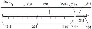
转到图2,除了电极阵列108之外,示例性耳蜗引线106还包括具有矩形部分128和锥形部分130的翼部126,该翼部126在植入手术期间用作外科医生的手柄。翼部126还为不笔直穿过所述翼部的导线134提供张力释放。可以由不同尺寸的管构成的管状构件132从翼部126延伸到壳体102。触点114连接到导线134(图4A),所述导线134穿过柔性本体112和管状构件132延伸到壳体102中的连接器(未示出)。Turning to FIG. 2, in addition to the
定位磁体136(图1)位于磁体袋138内。磁体136用于保持头戴式发射器相对于天线110的位置。在一些情况中,所述耳蜗植入物可以被构造为便于磁体的取出和更换。此处,壳体102可以设置有从磁体袋138延伸到壳体的外部的磁体孔(未示出)。Positioning magnet 136 ( FIG. 1 ) is located within
参考图4A和图4B,电极阵列108在垂直于电极阵列的纵向轴线A(图3)的横截面中具有截头圆形形状。所述横截面的外周的圆形部分(由触点114的外表面和柔性本体112的弯曲表面116两者限定)大于所述横截面的外周的一半。换句话说,触点114和弯曲表面116围绕电极阵列108的纵向轴线A延伸超过180度。在其他实施方式中,触点114和弯曲表面116可围绕纵向轴线A延伸130-180度。在此还应注意,本触点具有比传统触点大的暴露面积(区域),这使得能够实现更低的阻抗和更长的电池寿命。在图1-4B所示的实施例中,平坦表面122的长度小于截头圆的直径。Referring to FIGS. 4A and 4B , the
形成电极阵列(例如图1-4B中所示的电极阵列108)的一种示例性方法可以包括使用图5和图5A中所示的示例性模具200。模具200具有第一和第二模具部件202和204。第一模具部件202包括具有表面207的板206,所述表面207限定具有电极阵列108的形状的细长腔体208。考虑到电极阵列108的形状,细长腔体208在垂直于腔体的纵向轴线的横截面中具有截头圆形形状。开口210延伸穿过板206的顶表面212。开口210的宽度WO小于细长腔体208的最大宽度MW,因此,第一模具部件202包括限定底切211(图5B)的一对向内延伸的突出部209。One exemplary method of forming an electrode array, such as
示例性第一模具部件202的顶表面212还包括标记214,所述标记214在下面参考图6-17描述的过程之前和该过程期间与触点114的预期位置相对应。此处,触点114中的每一个具有一个标记214。在另一个实施方式(未示出)中,可以为触点114中的每一个设置一组四个标记214(在腔体208的每一侧上各两个)。标记组从腔体208的端部部分216延伸到所述腔体的基部部分218(图6)。第二模具部件204(其包括面向第一模具部件202的顶表面212(和开口210)的平坦底表面220)将在触点114已经按照下面描述的方式定位在腔体208内之后定位在所述第一模具部件上。平坦表面220使示例性柔性本体112的平坦表面122成形。第二模具部件204还包括用于注入形成柔性本体112的LSR(或其他弹性材料)的一个或多个入口222。The
在一些情况中,第一模具部件202可以是通过光刻工艺形成的一次性部件。尽管可以采用铁和其他可光刻材料,但是示例性第一模具部件202由相对便宜并且具有许多有利特性的铜形成。铜不太可能与铂触点114结合,因为铜不易于焊接并且具有相对高的热导率,这使得热量非常容易消散。铜还具有弹性,因此当铂触点工件(下面所讨论)被按压通过所述开口时,铜将稍微弯曲并将恢复其形状。铜易于弯曲,这有利于电极阵列的释放(下面所讨论)。而且,由于铜是导电的,所以它可以用于对焊工艺中,其中铜模具部件202形成电气回路(电路)的一部分。在其它实施方式中,模具部件202可以是可重复使用的装置,其包括由诸如不锈钢的较硬材料形成的两个可分离件。第二模具部件204可以是可重复使用的并且由不锈钢或任何其他合适的硬金属形成。In some cases,
还应注意,翼部126(图2)可以利用具有翼部形状的腔体并且在注入过程期间与模具200对齐的不锈钢模具(未示出)形成。It should also be noted that the wings 126 (FIG. 2) may be formed using a stainless steel mold (not shown) having a wing-shaped cavity and aligned with the
转到图6-7D,所述示例性方法包括将触点工件224放置在第一模具部件202上的由最靠近基部部分218的标记214限定的位置处。首先参考图6和图7,示例性触点工件224是通过由铂或其他合适的触点材料形成的壁226限定的管。尽管不限于任何特定形状,但示例性工件是圆柱形管并且横截面为圆形。触点工件224的直径大于开口210的宽度WO(图5A),因此,触点工件在被按照以下所述的方式压缩之前不能完全穿过所述开口。在所示的实施方式中,触点工件224的直径等于腔体208的直径。Turning to FIGS. 6-7D , the example method includes placing a
转到图7A,可以利用镊子或其他合适的工具通过向壁226的侧面施加力F来将触点工件224压缩成非圆形(例如,椭圆形)形状,直到触点工件的宽度略小于、等于或至多略大于开口210的宽度WO。然后,压缩的触点工件224可以通过开口210插入并进入腔体208(图7B)。在压缩的触点工件224的宽度略大于开口210的宽度WO的情况下,模具部件202的弹性将允许所述开口略微变宽。然后可以按照图7C中所示的方式向压缩的触点工件224的顶部施加力F,以使触点工件向外凸出成原始的圆形横截面形状或接近于原始的圆形横截面形状的形状(如图所示)。此处,部分触点工件224位于突出部209之下和底切211之内。然后,如图7D所示,将要连接到由工件224形成的触点114的导线134可以被定位在所述工件内。可以在将导线134的位于工件224内的部分插入工件中之前剥去其绝缘层,或者可以简单地允许在向工件施加热量和压力期间烧掉该绝缘层(下面参考图8所述)。Turning to FIG. 7A , tweezers or other suitable tool can be used to compress the
接下来,如图8所示,将热量和压力施加到触点工件上以形成触点114。将触点114紧紧地压靠在限定腔体208的模具表面207上,从而防止触点移动。表面207掩盖触点114的外表面并限定柔性本体112的在未被触点114覆盖的空间中的外表面。部分触点114位于突出部209之下和底切211之内。可延展工件224的压缩和变形还使得壁226的(多个)部分沿着接缝230彼此接触,其中导线134位于它们之间。在一些但不是所有情况下,并且在如图示的实施方式中的情况下,可以在壁226的其他部分之间形成间隙232。如下面参考图16所讨论的那样,间隙232增强了柔性本体112和触点114之间的机械互连。Next, as shown in FIG. 8 , heat and pressure are applied to the contact workpiece to form
然后,可以重复图6-8所示的步骤以形成其余的触点114。为此,参考图9,可以按照上面参考图7-7D描述的方式将下一个触点工件224放置在第一模具部件202上的由下一个相邻标记214限定的位置处。把将要连接到由该工件224形成的触点114的导线134定位在工件内并且使之在先前制备的触点上方延伸到并延伸超过腔体208的基部部分218。然后利用例如焊头(诸如电阻焊接工艺中的钼焊头228)将热量和压力施加到工件224上。热量和压力将工件224压靠在限定腔体208的表面207上,从而形成第二触点114(图10)。重复该过程直到在与腔体208的端部部分216相邻的区域中形成最后的触点114,如图11-13所示。The steps shown in FIGS. 6-8 may then be repeated to form the remaining
在其它实施方式中,触点114可以通过利用不锈钢焊头(不施加热量)压缩工件224然后利用钼焊头施加热量来形成,由此能够防止两个焊头上的磨损。In other embodiments, the
一旦所有触点114都已经形成并连接到相应的导线134,就可以将第二模具部件204放置在第一模具部件202上,以按照图14和图15中所示的方式完成模具200。可以使用夹具、螺钉或其他合适的工具(未示出)来将模具部件202和204保持在一起。然后可以将LSR或其他合适的弹性材料注入(或以其他方式引入)模具腔体208中以形成柔性本体112。模具表面207的掩盖效果防止弹性材料溢料到触点114的外表面上。在弹性材料硬化之后,可以将模具部件202和204彼此分开。可以例如按照图15A所示的方式通过弯曲模具部件202以便增加开口210的宽度WO来将完成的电极阵列108从腔体208中取出。然后可以处理掉弯曲和/或破裂的模具部件202。Once all
转到图16,现已完成的电极阵列108包括上述柔性本体112、触点114和导线134。柔性本体112的平坦表面122不包括触点114或其他导电元件。在所示实施例中,触点114围绕纵向轴线A延伸超过180度。在其他实施例中,所述触点可围绕纵向轴线A延伸180度或小于180度。由于表面207的掩盖效果,触点114的外表面没有弹性材料。导线134各自连接到相应的一个触点并穿过由其他触点限定的开放中心区域。柔性本体112的(多个)部分与触点间隙232定位在一起,从而增强了柔性本体112和触点114之间的机械互连。Turning to FIG. 16 , the now completed
在图17所示的流程图中总结了上述各个方法步骤。将第一工件224定位在第一模具部件202内的如由与腔体208的基部部分218相邻的记号214所标识的预期位置处(步骤S01)。将导线134放置在工件224内(步骤S02)。此处应该注意,步骤S01和S02的顺序可以颠倒,或者步骤S01和S02可以同时执行。然后通过使用例如由焊头228施加的热量和压力来压缩工件224,以形成触点114(步骤S03)。重复该过程直到所有触点114都已形成在模具腔体208内(步骤S04)。一旦所有触点114都已形成,就可以将第二模具部件204放置在第一模具部件202上(步骤S05),并且可以将LSR或其他弹性材料注入模具腔体208中(步骤S06)。在弹性材料已经固化之后,可以从第一模具部件202中取出完成的电极阵列108(步骤S07)。The various method steps described above are summarized in the flowchart shown in FIG. 17 . The
本装置和方法不限于上述示例性实施方式。在本方法的其他实施方式中,所有工件224都可以在没有导线134的情况下定位在第一模具部件202的腔体208内。此后,并且从最接近腔体208的基部部分218的工件224开始,可以将导线134插入工件中并且可以压缩该工件(例如,利用通过焊头施加的热量和压力)以形成触点114。可以重复该过程直到最后的触点114已经形成在腔体208内。然后可以按照上述方式将LSR或其他弹性材料注入模具腔体208中以完成电极阵列108。The present apparatus and method are not limited to the exemplary embodiments described above. In other embodiments of the method, all
本方法还可用于形成其他具有平坦表面的电极阵列以及具有弯曲或其他非平坦表面的阵列。作为示例而非限制,图18中示出的示例性模具200a基本上类似于模具200并且类似的元件由类似的附图标记来表示。然而,此处,第二模具部件204a包括与第一模具部件202的开口210对准的凹槽220a。由模具200a产生的电极阵列108a(图19)基本上类似于电极阵列108并且类似的元件由类似的附图标记来表示。然而,此处,柔性本体112a的平坦表面122a与触点114之间的距离大于柔性本体112的平坦表面122与触点114之间的距离(图16)。The method can also be used to form other electrode arrays with planar surfaces as well as arrays with curved or otherwise non-planar surfaces. By way of example and not limitation, the
转到图20和图21,示例性模具200b基本上类似于模具200并且类似的元件由类似的附图标记来表示。然而,此处,第一模具部件202b包括具有在垂直于所述腔体的纵向轴线的横截面中呈半圆形(即180度)的细长腔体208b的板206b。开口210b延伸穿过板206b的顶表面212。开口210b的宽度等于工件224的直径。因此,当工件被放置在第一模具部件202b上时,工件224穿过开口210b并进入腔体208b中,而不需要以上参考图7-7D所描述的压缩。工件224可以被压缩(例如,通过由焊头施加的热量和压力),以形成连接到导线134的具有接缝230b的半圆形触点114b。一旦所有触点114b都已形成并连接到相应的导线134,就可以将第二模具部件204放置在第一模具部件202b上以完成模具200b。然后可以将LSR或其他合适的弹性材料注入模具腔体208b中,以形成图22所示的电极阵列108b的柔性本体112b。电极阵列108b基本上类似于电极阵列108并且类似的元件由类似的附图标记来表示。然而,此处,柔性本体112a的平坦表面122a的宽度等于半圆形电极阵列108b的直径,这允许在不弯曲和/或破坏所述模具部件的情况下将电极阵列108b从模具部件202b中取出。Turning to FIGS. 20 and 21 , the
例如,如图23中所示,示例性电极阵列108可以按照以下方式定位在耳蜗C的鼓阶ST内,所述方式为使柔性本体112的平坦表面122面向外侧壁LW并且使触点114面向内侧壁MW。在将电极阵列108插入耳蜗期间,平坦表面122的一些或全部抵靠所述外侧壁定位,从而降低了电极阵列扭转的可能性。优选地,平坦表面122在整个插入过程中(即从端部118通过圆窗(或耳蜗造口)进入耳蜗直到电极阵列108的具有触点114的部分已经通过圆窗(或耳蜗造口)并且位于耳蜗内时)保持抵靠外侧表面LW。柔性本体112的触点114和弯曲表面116在插入期间(以及插入之后)面向耳蜗内的蜗轴和内侧壁MW。For example, as shown in FIG. 23 , an
应注意,本装置和方法不限于具有平坦表面的电极阵列。为此,参考图24,示例性模具200c基本上类似于模具200并且类似的元件由类似的附图标记来表示。然而,此处,第二模具部件204c包括与第一模具部件202的开口210对准的凹槽220c。凹槽220c的曲率半径等于凹槽208的曲率半径。因此,当组合时,凹槽208和凹槽220c在垂直于凹槽208的纵向轴线的平面中限定出一个圆。由模具200c产生的电极阵列108c(图25)基本上类似于电极阵列108并且类似的元件由类似的附图标记来表示。然而,此处,由柔性本体112c和触点114限定的电极阵列108c在横截面中呈圆形。示例性电极阵列108c可以按照图26中所示的方式定位在耳蜗C的鼓阶ST内。It should be noted that the present devices and methods are not limited to electrode arrays having flat surfaces. To this end, referring to FIG. 24 , an
尽管已经根据上述优选实施例描述了本文公开的本发明,但是对于本领域技术人员来说,对上述优选实施例的许多修改和/或添加是显而易见的。作为示例而非限制,本发明包括尚未被描述的来自在说明书中公开的各种类型和实施例的元件的任何组合。其意图是将本发明的范围扩展到所有这些修改和/或添加,并且本发明的范围仅仅被下面提出的权利要求所限制。Although the invention disclosed herein has been described in terms of the above preferred embodiments, many modifications and/or additions to the above preferred embodiments will be apparent to those skilled in the art. By way of example and not limitation, the present invention includes any combination of elements from the various types and embodiments disclosed in the specification that has not yet been described. It is intended that the scope of the present invention be extended to all such modifications and/or additions, and that the scope of the present invention be limited only by the claims set forth below.
Claims (16)
Applications Claiming Priority (1)
| Application Number | Priority Date | Filing Date | Title |
|---|---|---|---|
| PCT/US2016/046621 WO2018031025A1 (en) | 2016-08-11 | 2016-08-11 | Cochlear implants including electrode arrays and methods of making the same |
Publications (2)
| Publication Number | Publication Date |
|---|---|
| CN109562259A CN109562259A (en) | 2019-04-02 |
| CN109562259B true CN109562259B (en) | 2023-06-27 |
Family
ID=56799587
Family Applications (1)
| Application Number | Title | Priority Date | Filing Date |
|---|---|---|---|
| CN201680088333.1A Active CN109562259B (en) | 2016-08-11 | 2016-08-11 | Cochlear implant comprising electrode array and method for manufacturing electrode array |
Country Status (4)
| Country | Link |
|---|---|
| US (2) | US11103703B2 (en) |
| EP (1) | EP3496805B1 (en) |
| CN (1) | CN109562259B (en) |
| WO (1) | WO2018031025A1 (en) |
Families Citing this family (11)
| Publication number | Priority date | Publication date | Assignee | Title |
|---|---|---|---|---|
| CN109562259B (en) | 2016-08-11 | 2023-06-27 | 领先仿生公司 | Cochlear implant comprising electrode array and method for manufacturing electrode array |
| WO2018089272A1 (en) | 2016-11-08 | 2018-05-17 | Advanced Bionics Ag | Electrode arrays and cochlear implants including the same |
| CN116688353A (en) | 2016-12-01 | 2023-09-05 | 领先仿生公司 | Contact array assembly, cochlear implant, and method of forming cochlear implant electrode array |
| US12496440B2 (en) * | 2019-10-10 | 2025-12-16 | Advanced Bionics Ag | Apparatus and methods for making cochlear implant electrode arrays |
| US11452865B2 (en) | 2019-10-10 | 2022-09-27 | Advanced Bionics Ag | Apparatus and methods for making cochlear implant electrode arrays |
| US11471668B2 (en) | 2019-12-21 | 2022-10-18 | Advanced Bionics Ag | Apparatus and methods for making cochlear implant electrode arrays |
| US20230091164A1 (en) | 2020-03-31 | 2023-03-23 | Sara Elizabeth CLABEAUX | Cochlear implant electrode arrays having orientation indicators and cochlear implants including the same |
| CN114949598B (en) * | 2022-05-17 | 2023-03-07 | 深圳市美好创亿医疗科技股份有限公司 | Artificial cochlea ear hanging machine and implant |
| USD1083111S1 (en) * | 2022-10-14 | 2025-07-08 | In Sang Choi | Electrosurgical electrode |
| EP4483941A1 (en) | 2023-06-30 | 2025-01-01 | Advanced Bionics LLC | Cochlear implant electrode arrays and electrode array cover assemblies for use with the same |
| WO2025136387A1 (en) | 2023-12-20 | 2025-06-26 | Advanced Bionics, Llc | Multi-material contacts and cochlear implants including the same |
Family Cites Families (61)
| Publication number | Priority date | Publication date | Assignee | Title |
|---|---|---|---|---|
| US4686765A (en) | 1984-05-03 | 1987-08-18 | Regents Of The University Of California | Method for making an intracochlear electrode array |
| US4819647A (en) * | 1984-05-03 | 1989-04-11 | The Regents Of The University Of California | Intracochlear electrode array |
| FR2629710B1 (en) | 1988-04-08 | 1997-10-24 | Mxm | ELECTRODE HOLDER DEVICES IMPLANTABLE IN THE COCHLEE FOR ELECTRICALLY STIMULATING THE HEARING NERVE |
| US5000194A (en) | 1988-08-25 | 1991-03-19 | Cochlear Corporation | Array of bipolar electrodes |
| US4961434A (en) * | 1988-08-30 | 1990-10-09 | Stypulkowski Paul H | Array of recessed radially oriented bipolar electrodes |
| US5037497A (en) | 1988-08-30 | 1991-08-06 | Cochlear Corporation | Method of fabricating an array of recessed radially oriented bipolar electrodes |
| US5439485A (en) | 1993-09-24 | 1995-08-08 | Ventritex, Inc. | Flexible defibrillation electrode of improved construction |
| US5580699A (en) | 1994-08-16 | 1996-12-03 | Ventritex, Inc. | Method for manufacturing implantable cardiac defibrillation electrodes using a laser beam material removal process |
| US5534022A (en) | 1994-11-22 | 1996-07-09 | Ventritex, Inc. | Lead having an integrated defibrillation/sensing electrode |
| US5824022A (en) | 1996-03-07 | 1998-10-20 | Advanced Bionics Corporation | Cochlear stimulation system employing behind-the-ear speech processor with remote control |
| AU746636B2 (en) * | 1997-03-10 | 2002-05-02 | Med-El Elektromedizinische Gerate Gmbh | Apparatus and method for perimodiolar cochlear implant with retro-positioning |
| US6038484A (en) * | 1997-09-02 | 2000-03-14 | Advanced Bionics Corporation | Cochlear electrode with modiolar-hugging system including a flexible positioner |
| US6129753A (en) | 1998-03-27 | 2000-10-10 | Advanced Bionics Corporation | Cochlear electrode array with electrode contacts on medial side |
| US6119044A (en) * | 1997-06-02 | 2000-09-12 | Advanced Bionics Corporation | Cochlear electrode array with positioning stylet |
| US6125302A (en) * | 1997-09-02 | 2000-09-26 | Advanced Bionics Corporation | Precurved modiolar-hugging cochlear electrode |
| US6266568B1 (en) * | 1998-06-02 | 2001-07-24 | Advanced Bionics Corporation | Inflatable cochlear electrode array and method of making same |
| US6309410B1 (en) | 1998-08-26 | 2001-10-30 | Advanced Bionics Corporation | Cochlear electrode with drug delivery channel and method of making same |
| US6304787B1 (en) * | 1998-08-26 | 2001-10-16 | Advanced Bionics Corporation | Cochlear electrode array having current-focusing and tissue-treating features |
| US6195586B1 (en) * | 1998-08-26 | 2001-02-27 | Advanced Bionics Corporation | Space-filling cochlear electrode |
| US6862805B1 (en) * | 1998-08-26 | 2005-03-08 | Advanced Bionics Corporation | Method of making a cochlear electrode array having current-focusing and tissue-treating features |
| US6889094B1 (en) * | 1999-05-14 | 2005-05-03 | Advanced Bionics Corporation | Electrode array for hybrid cochlear stimulator |
| EP2042137B1 (en) | 1999-05-21 | 2013-06-26 | Cochlear Limited | A cochlear implant electrode array |
| US6256533B1 (en) * | 1999-06-09 | 2001-07-03 | The Procter & Gamble Company | Apparatus and method for using an intracutaneous microneedle array |
| US6374143B1 (en) * | 1999-08-18 | 2002-04-16 | Epic Biosonics, Inc. | Modiolar hugging electrode array |
| JP5124074B2 (en) * | 2000-06-30 | 2013-01-23 | コクレア リミテッド | Cochlear implant |
| US20030236562A1 (en) * | 2000-10-10 | 2003-12-25 | Kuzma Janusz A. | Band type multicontact electrode and method of making the same |
| JP3971996B2 (en) | 2000-11-29 | 2007-09-05 | コックリアー,リミテッド | Pre-curved cochlear implant electrode array |
| US20070088335A1 (en) * | 2001-10-24 | 2007-04-19 | Med-El Elektromedizinische Geraete Gmbh | Implantable neuro-stimulation electrode with fluid reservoir |
| CA2693332C (en) * | 2007-07-20 | 2013-01-15 | Nippon Steel Corporation | Method for hydroforming and a hydroformed product |
| US20130079749A1 (en) * | 2007-08-29 | 2013-03-28 | Advanced Bionics, Llc | Modular Drug Delivery System for Minimizing Trauma During and After Insertion of a Cochlear Lead |
| EP2209520B1 (en) | 2007-11-16 | 2013-10-02 | Cochlear Americas | Electrode array and method of forming an electrode array |
| WO2009079704A1 (en) | 2007-12-21 | 2009-07-02 | Cochlear Limited | Electrode array assembly |
| US20090306745A1 (en) | 2008-03-31 | 2009-12-10 | Cochlear Limited | Electrode assembly for delivering longitudinal and radial stimulation |
| WO2010017116A2 (en) | 2008-08-08 | 2010-02-11 | Med-El Elektromedizinische Geraete Gmbh | Laser-based fabrication of implantable stimulation electrodes |
| US8886334B2 (en) * | 2008-10-07 | 2014-11-11 | Mc10, Inc. | Systems, methods, and devices using stretchable or flexible electronics for medical applications |
| US8788064B2 (en) | 2008-11-12 | 2014-07-22 | Ecole Polytechnique Federale De Lausanne | Microfabricated neurostimulation device |
| KR101088806B1 (en) * | 2009-01-07 | 2011-12-01 | 주식회사 뉴로바이오시스 | Microelectrode array package using liquid crystal polymer and manufacturing method thereof |
| CZ305749B6 (en) * | 2009-01-20 | 2016-03-02 | Bvt Technologies A. S. | Electrochemical sensor and process for producing thereof |
| US20100287770A1 (en) | 2009-05-14 | 2010-11-18 | Cochlear Limited | Manufacturing an electrode carrier for an implantable medical device |
| US8880193B1 (en) * | 2009-05-22 | 2014-11-04 | Advanced Bionics, Llc | Cochlear electrode array |
| US8712554B2 (en) | 2009-07-21 | 2014-04-29 | Advanced Bionics | Integrated wire carrier for electrode array |
| US8461042B2 (en) | 2009-12-01 | 2013-06-11 | Cochlear Limited | Electrode contact contaminate removal |
| US8782884B2 (en) | 2009-12-01 | 2014-07-22 | Cochlear Limited | Manufacturing an electrode assembly having contoured electrode contact surfaces |
| US20130238074A1 (en) * | 2010-06-30 | 2013-09-12 | Med-El Elektromedizinische Geraete Gmbh | Ear Implant Electrode and Method of Manufacture |
| EP2675521A1 (en) * | 2011-02-17 | 2013-12-25 | Advanced Bionics AG | Wire constructs |
| EP2707085B1 (en) * | 2011-05-11 | 2021-03-24 | Advanced Bionics AG | Mid-scalar electrode array |
| EP2755617B1 (en) | 2011-09-13 | 2018-07-04 | Hear Ip Pty Ltd | Method for fabrication biocompatible electrode component |
| DE102011119125B4 (en) * | 2011-11-23 | 2014-01-23 | Heraeus Precious Metals Gmbh & Co. Kg | Contacting arrangement with bushing and filter structure |
| EP2897684B1 (en) | 2012-09-20 | 2017-05-31 | Advanced Bionics AG | Implantable body with a lead and with engagement wings |
| US10124167B2 (en) * | 2013-03-13 | 2018-11-13 | Advanced Bionics Ag | Magnet installation systems and methods for use with cochlear implants |
| EP2994191A1 (en) | 2013-05-10 | 2016-03-16 | Advanced Bionics AG | Thin profile cochlear implants |
| EP3038702B1 (en) * | 2013-08-27 | 2019-02-27 | Advanced Bionics AG | Thermoformed electrode arrays |
| US9480838B2 (en) | 2013-10-15 | 2016-11-01 | Med-El Elektromedizinische Geraete Gmbh | Cochlear electrode with apical lateral wall section and basal modiolar hugging section |
| WO2016012882A2 (en) * | 2014-07-24 | 2016-01-28 | Cochlear Limited | Implanted medical devices having electrode assemblies |
| WO2017037613A1 (en) | 2015-08-28 | 2017-03-09 | Cochlear Limited | Implantable stimulating assembly |
| CN109562259B (en) | 2016-08-11 | 2023-06-27 | 领先仿生公司 | Cochlear implant comprising electrode array and method for manufacturing electrode array |
| CN116688353A (en) | 2016-12-01 | 2023-09-05 | 领先仿生公司 | Contact array assembly, cochlear implant, and method of forming cochlear implant electrode array |
| CN208492977U (en) | 2017-05-19 | 2019-02-15 | 山东大学 | Multilayered structure flexibility artificial hearing Neural stimulation electrodes |
| US11452865B2 (en) | 2019-10-10 | 2022-09-27 | Advanced Bionics Ag | Apparatus and methods for making cochlear implant electrode arrays |
| US12496440B2 (en) | 2019-10-10 | 2025-12-16 | Advanced Bionics Ag | Apparatus and methods for making cochlear implant electrode arrays |
| US11471668B2 (en) | 2019-12-21 | 2022-10-18 | Advanced Bionics Ag | Apparatus and methods for making cochlear implant electrode arrays |
-
2016
- 2016-08-11 CN CN201680088333.1A patent/CN109562259B/en active Active
- 2016-08-11 WO PCT/US2016/046621 patent/WO2018031025A1/en not_active Ceased
- 2016-08-11 EP EP16756882.3A patent/EP3496805B1/en active Active
- 2016-08-11 US US16/319,638 patent/US11103703B2/en active Active
-
2021
- 2021-07-23 US US17/384,666 patent/US11986654B2/en active Active
Also Published As
| Publication number | Publication date |
|---|---|
| EP3496805B1 (en) | 2021-02-17 |
| US11986654B2 (en) | 2024-05-21 |
| US20200188666A1 (en) | 2020-06-18 |
| WO2018031025A1 (en) | 2018-02-15 |
| EP3496805A1 (en) | 2019-06-19 |
| US20210346697A1 (en) | 2021-11-11 |
| US11103703B2 (en) | 2021-08-31 |
| CN109562259A (en) | 2019-04-02 |
Similar Documents
| Publication | Publication Date | Title |
|---|---|---|
| CN109562259B (en) | Cochlear implant comprising electrode array and method for manufacturing electrode array | |
| US12036402B2 (en) | Cochlear implants including electrode arrays and methods of making the same | |
| US11058871B2 (en) | Manufacturing an electrode array for a stimulating medical device | |
| US12420096B2 (en) | Electrode arrays and cochlear implants including the same | |
| US12496440B2 (en) | Apparatus and methods for making cochlear implant electrode arrays | |
| US11452865B2 (en) | Apparatus and methods for making cochlear implant electrode arrays | |
| US11471668B2 (en) | Apparatus and methods for making cochlear implant electrode arrays | |
| US20220062627A1 (en) | Manufacturing an electrode array for a stimulating medical device | |
| WO2025136387A1 (en) | Multi-material contacts and cochlear implants including the same | |
| KR100506503B1 (en) | Mold for cochlear electrode and its fabricating method using micro-machining technology | |
| US20230091164A1 (en) | Cochlear implant electrode arrays having orientation indicators and cochlear implants including the same | |
| WO2017068383A1 (en) | Apparatus and methods for adjusting the curvature of cochlear implant electrode arrays |
Legal Events
| Date | Code | Title | Description |
|---|---|---|---|
| PB01 | Publication | ||
| PB01 | Publication | ||
| SE01 | Entry into force of request for substantive examination | ||
| SE01 | Entry into force of request for substantive examination | ||
| GR01 | Patent grant | ||
| GR01 | Patent grant |