CN109542094B - Visual Stabilization Control of Mobile Robots with Unexpected Images - Google Patents
Visual Stabilization Control of Mobile Robots with Unexpected Images Download PDFInfo
- Publication number
- CN109542094B CN109542094B CN201710885886.6A CN201710885886A CN109542094B CN 109542094 B CN109542094 B CN 109542094B CN 201710885886 A CN201710885886 A CN 201710885886A CN 109542094 B CN109542094 B CN 109542094B
- Authority
- CN
- China
- Prior art keywords
- robot
- coordinate system
- pose
- mobile robot
- axis
- Prior art date
- Legal status (The legal status is an assumption and is not a legal conclusion. Google has not performed a legal analysis and makes no representation as to the accuracy of the status listed.)
- Expired - Fee Related
Links
Images


Classifications
-
- G—PHYSICS
- G05—CONTROLLING; REGULATING
- G05D—SYSTEMS FOR CONTROLLING OR REGULATING NON-ELECTRIC VARIABLES
- G05D1/00—Control of position, course, altitude or attitude of land, water, air or space vehicles, e.g. using automatic pilots
- G05D1/02—Control of position or course in two dimensions
- G05D1/021—Control of position or course in two dimensions specially adapted to land vehicles
- G05D1/0231—Control of position or course in two dimensions specially adapted to land vehicles using optical position detecting means
- G05D1/0246—Control of position or course in two dimensions specially adapted to land vehicles using optical position detecting means using a video camera in combination with image processing means
-
- G—PHYSICS
- G06—COMPUTING OR CALCULATING; COUNTING
- G06T—IMAGE DATA PROCESSING OR GENERATION, IN GENERAL
- G06T1/00—General purpose image data processing
- G06T1/0014—Image feed-back for automatic industrial control, e.g. robot with camera
-
- G—PHYSICS
- G06—COMPUTING OR CALCULATING; COUNTING
- G06T—IMAGE DATA PROCESSING OR GENERATION, IN GENERAL
- G06T7/00—Image analysis
- G06T7/70—Determining position or orientation of objects or cameras
- G06T7/73—Determining position or orientation of objects or cameras using feature-based methods
-
- G—PHYSICS
- G06—COMPUTING OR CALCULATING; COUNTING
- G06T—IMAGE DATA PROCESSING OR GENERATION, IN GENERAL
- G06T2207/00—Indexing scheme for image analysis or image enhancement
- G06T2207/30—Subject of image; Context of image processing
- G06T2207/30241—Trajectory
Landscapes
- Engineering & Computer Science (AREA)
- Physics & Mathematics (AREA)
- General Physics & Mathematics (AREA)
- Computer Vision & Pattern Recognition (AREA)
- Theoretical Computer Science (AREA)
- Multimedia (AREA)
- Robotics (AREA)
- Electromagnetism (AREA)
- Aviation & Aerospace Engineering (AREA)
- Radar, Positioning & Navigation (AREA)
- Remote Sensing (AREA)
- Automation & Control Theory (AREA)
- Manipulator (AREA)
- Control Of Position, Course, Altitude, Or Attitude Of Moving Bodies (AREA)
Abstract
一种移动机器人的无期望图像视觉伺服方法。本文提出了移动机器人的无期望图像视觉伺服方法,能够在期望图像无法事先获得的情况下,将移动机器人由当前位姿镇定至任意指定位姿处。首先,为了处理期望图像确实的情况,根据目标特征定义了参考坐标系,并引入了比例意义下的临时期望坐标系。镇定过程分为两个阶段,首先求取当前坐标系与临时期望坐标系之间的极坐标关系,即可得到以极坐标表示下的系统误差。之后根据移动机器人的运动学方程,设计基于极坐标的镇定控制律。并根据并发学习策略,设计能辨识未知特征点高度信息的自适应更新律。进而移动机器人的镇定过程中,同时将特征点高度辨识出,并可以得到机器人的全状态信息。此后在第二阶段中,利用移动机器人的全状态信息,根据极坐标控制方法,将其由临时期望坐标系镇定至任意指定的期望坐标系处。

An undesired image visual servoing method for mobile robots. This paper proposes an undesired image visual servoing method for mobile robots, which can stabilize the mobile robot from the current pose to any specified pose when the desired image cannot be obtained in advance. First, in order to deal with the fact that the desired image is true, a reference coordinate system is defined according to the target features, and a temporary desired coordinate system in the sense of scale is introduced. The stabilization process is divided into two stages. First, the polar coordinate relationship between the current coordinate system and the temporary desired coordinate system is obtained, and then the system error expressed in polar coordinates can be obtained. Then, according to the kinematic equation of the mobile robot, a stabilization control law based on polar coordinates is designed. According to the concurrent learning strategy, an adaptive update law that can identify the height information of unknown feature points is designed. Then, during the stabilization process of the mobile robot, the feature points are highly identified at the same time, and the full state information of the robot can be obtained. After that, in the second stage, using the full state information of the mobile robot, according to the polar coordinate control method, it is stabilized from the temporary desired coordinate system to an arbitrarily specified desired coordinate system.
Description
技术领域technical field
本发明属于计算机视觉与移动机器人的技术领域,特别是涉及一种无期望图像的移动机器人视觉镇定控制方法。The invention belongs to the technical field of computer vision and mobile robots, and in particular relates to a visual stabilization control method of a mobile robot with undesired images.
背景技术Background technique
近年来,通过视觉反馈手段来控制操作臂和轮式移动机器人等智能设备的问题,已经成为控制理论和机器人应用的重要方向。在通常情况下,期望图像在视觉伺服中起到了很重要的作用,其作用是为机器人系统定义期望位姿。然而,对于未提前获取期望图像或机器人在陌生的场景下运行的情况,现有方法无法适用。本文中,我们将研究轮式移动机器人系统的视觉伺服问题,其中目标位姿处对应的期望图像是不存在的。对于机器人来说,一个主要的任务是能够移动到任意指定位姿处。然而,由于非完整性约束和场景深度缺乏等原因,移动机器人的视觉控制是十分困难的。为了完成无期望图像的控制目标,必须充分利用图像信息,辨识出场景模型。当不存在期望图像时,控制问题变得更加复杂,加之目标模型和视觉深度信息是未知的,又考虑到非完整特性的存在,无期望图像视觉伺服在机器人和控制领域是一个非常具有挑战性且有趣的问题。In recent years, the problem of controlling intelligent devices such as manipulators and wheeled mobile robots by means of visual feedback has become an important direction in control theory and robot applications. In general, the desired image plays an important role in visual servoing, and its role is to define the desired pose for the robotic system. However, for situations where the desired image is not acquired in advance or the robot operates in an unfamiliar scene, existing methods cannot be applied. In this paper, we will study the visual servoing problem of wheeled mobile robotic systems, where the desired image corresponding to the target pose does not exist. For robots, a major task is to be able to move to any given pose. However, visual control of mobile robots is very difficult due to non-integrity constraints and lack of scene depth. In order to complete the control objective of undesired images, the image information must be fully utilized to identify the scene model. When the desired image does not exist, the control problem becomes more complicated. In addition, the target model and visual depth information are unknown, and considering the existence of non-holonomic characteristics, the visual servoing of undesired images is a very challenging in the field of robotics and control. and interesting question.
许多研究者把他们的注意力都集中在处理机器人操作臂的视觉控制问题,并得到了许多有意义的研究成果。对于经典的方法,基于位置和基于图像的视觉伺服系统利用当前和期望的图像分别产生位姿误差和图像误差,而混合视觉伺服则包含了从期望和当前图像中提取出的图像特征和旋转运动。通过计算关系矩阵得到所涉及到的整个图像的光度信息来代替点特征的使用,使这些方法在遮蔽和反光的场景下也能适用。然而,也可利用密集的深度图和像素强度增加系统在外部干扰下的鲁棒性。为了满足物理约束和避免碰撞,从初始位姿到期望位姿来规划末端操作器路径是一个好的解决方法。为了处理内部不确定因素,采用一些无标定的视觉伺服方法来处理未知的摄像机内参数和未知的操作臂模型。基于视觉伺服结构,机器人操作臂可以完成目标跟踪和处理目标畸变等多项任务。不幸的是,上述所有方法都需要期望图像来完成视觉伺服任务,而这些任务能够为机器人操作臂提供参考位姿。众所周知,在没有提前捕获期望图的情况下,这种示教模式是无法运作的。Many researchers have focused their attention on the problem of visual control of robotic manipulators, and have obtained many meaningful research results. For classical methods, position-based and image-based visual servoing utilizes the current and desired images to generate pose and image errors, respectively, while hybrid visual servoing incorporates image features and rotational motion extracted from desired and current images . The photometric information of the whole image involved is obtained by calculating the relation matrix instead of the use of point features, so that these methods can also be applied in shading and reflective scenes. However, dense depth maps and pixel intensities can also be utilized to increase the robustness of the system to external disturbances. To meet physical constraints and avoid collisions, planning the end effector path from the initial pose to the desired pose is a good solution. In order to deal with the internal uncertainties, some uncalibrated visual servoing methods are adopted to deal with unknown camera parameters and unknown manipulator model. Based on the visual servo structure, the robot manipulator can complete multiple tasks such as target tracking and target distortion processing. Unfortunately, all of the above methods require expected images to perform visual servoing tasks that provide reference poses for robotic manipulators. It is well known that this teaching mode cannot work without capturing the desired map ahead of time.
相比于机器人操作臂,轮式移动机器人有操作灵活和工作空间宽阔的优势,通过视觉信息控制机器人一直是机器人领域的一个活跃的研究课题。由于期望图像、当前图像和初始图像的存在,移动机器人的状态信息可以由单应性、基本矩阵和三焦张量估计出。为了处理位姿控制中的非完整性约束,采用平滑时变控制、基于极坐标控制和转换控制将机器人镇定到期望位姿处。为了处理未知的信息深度,通常在视觉伺服系统中引入自适应补偿机制。将深度信息作为已知动力学方程的不可测量参数,并引入非线性观测器来辨识视觉调节过程中的特征深度。在自适应更新律识别目标特征位姿之后,移动机器人的位姿是可测量的。为了保持摄像机视野中的图像信息,采用一些基于主动视觉和基于路径规划的方法来使移动机器人进行适当移动。此外,对于视觉轨迹跟踪任务,附加的静态图像是为期望轨迹和当前轨迹提供参考的必要条件。然而,在上述方法中,视觉伺服目标需要期望图像意味着移动机器人可以在预先捕获期望图像的前提下到达目标位姿,并且机器人只能在熟悉的场景中运行。因此,在没有预先获取期望图像的情况下,将基于视觉的移动机器人镇定到期望位姿处,则整个系统将变得更加智能。Compared with robot manipulators, wheeled mobile robots have the advantages of flexible operation and wide working space, and controlling robots through visual information has always been an active research topic in the field of robotics. Due to the existence of the desired image, the current image and the initial image, the state information of the mobile robot can be estimated from the homography, fundamental matrix and trifocal tensor. In order to deal with the non-integrity constraints in pose control, smooth time-varying control, polar coordinate-based control and transformation control are used to stabilize the robot to the desired pose. In order to deal with the unknown depth of information, an adaptive compensation mechanism is usually introduced in the visual servo system. The depth information is taken as an unmeasurable parameter of the known dynamic equation, and a nonlinear observer is introduced to identify the characteristic depth in the process of visual accommodation. After the adaptive update law identifies the target feature pose, the pose of the mobile robot is measurable. In order to keep the image information in the field of view of the camera, some methods based on active vision and based on path planning are adopted to make the mobile robot move properly. Furthermore, for the visual trajectory tracking task, additional static images are necessary to provide a reference for the desired trajectory and the current trajectory. However, in the above method, the vision servoing target needs the desired image, which means that the mobile robot can reach the target pose on the premise of capturing the desired image in advance, and the robot can only operate in the familiar scene. Therefore, if the vision-based mobile robot is stabilized to the desired pose without pre-acquiring the desired image, the entire system will become more intelligent.
为了实现无期望图像的视觉伺服任务,需要在控制算法中实现视觉目标模型的在线学习。最近,关于机器人系统的视觉深度辨识,已经获得了一些研究成果。基于含积分符号的稳定误差,对静态和动态场景分别设计非线性观测器来识别特征深度和摄像机速度。基于成像系统中可测量的运动参数,设计了一种非线性观测器来渐进地估计照相机的坐标。例如操纵器和水下航空器等各种机器人系统,也都应用到了图像数据的深度辨识算法。然而,现有的方法通常需要持续激励的条件,并且不能保证控制器与观测器组合的结构的全局稳定。当配备用于测量视觉目标深度的距离传感器时,系统复杂性和成本将增加,并且传感器也存在一定的误差。因此,无论在实际上还是在理论上,利用图像和运动信息来识别目标模型都是有益的。研究者们开发了一种用于不确定线性动力系统的并发学习自适应控制律,它同时利用历史和当前数据进行未知参数更新,并保证辨识和控制误差同时收敛。对于操作臂的视觉伺服,一些研究者设计了一种并发学习适应机制,可以在没有持续激励的轨迹跟踪过程中重建场景结构。本发明提供了一种新颖的视觉伺服策略,用于将轮式移动机器人镇定到期望位姿处,而不需要在现有方法中提前捕获期望图像。In order to realize the visual servoing task of undesired images, online learning of the visual target model needs to be implemented in the control algorithm. Recently, some research results have been obtained on visual depth recognition for robotic systems. Based on the stable error with integral sign, nonlinear observers are designed to identify feature depth and camera speed for static and dynamic scenes, respectively. Based on the measurable motion parameters in the imaging system, a nonlinear observer is designed to asymptotically estimate the coordinates of the camera. Various robotic systems, such as manipulators and underwater aircraft, are also applied to the depth recognition algorithm of image data. However, existing methods usually require the condition of continuous excitation, and cannot guarantee the global stability of the structure of the combined controller and observer. When equipped with a distance sensor for measuring the depth of a visual target, the system complexity and cost will increase, and the sensor also has certain errors. Therefore, it is beneficial to use image and motion information to identify target models, both in practice and in theory. Researchers have developed a concurrent learning adaptive control law for uncertain linear dynamical systems, which utilizes both historical and current data to update unknown parameters and guarantees the simultaneous convergence of identification and control errors. For visual servoing of manipulators, some researchers have designed a concurrent learning adaptation mechanism that can reconstruct the scene structure during trajectory tracking without continuous excitation. The present invention provides a novel visual servoing strategy for stabilizing a wheeled mobile robot to a desired pose without the need to capture the desired image in advance in existing methods.
发明内容SUMMARY OF THE INVENTION
本发明的目的是解决现有移动机器人视觉镇定控制存在的不足,提供了一种移动机器人的无期望图像视觉伺服方法。The purpose of the present invention is to solve the deficiencies in the visual stabilization control of the existing mobile robots, and to provide an undesired image visual servo method of the mobile robot.
本发明提出了一种新颖的移动机器人的无期望图像视觉伺服方法。该方法最大的特点是能够在期望图像无法事先获得的情况下,将移动机器人由当前位姿镇定至任意指定位姿处。因而,在未提前获取期望图像的情况下或在陌生的场景下,解决了现有的方法无法使机器人运行的问题,并且无需外加距离传感器,不增加系统复杂度和成本。具体而言,由于不存在期望图像,因此首先对于视觉目标定义参考系。然后,引入比例意义下的临时期望坐标系,使整个调节任务分为两个阶段。第一阶段,在当前坐标系和临时期望坐标系之间获得极坐标关系,然后设计自适应镇定控制律将移动机器人镇定至临时坐标系,其中根据基于并发学习结构的历史和当前数据为未知特征高度构建参数更新律。采用李雅普诺夫法严格地证明位姿调节误差和高度辨识误差可以同时收敛到零。之后,可以通过所辨识的特征高度来估计移动机器人的全状态信息,并通过极坐标控制律将移动机器人从临时坐标系驱动到期望坐标系。仿真与实验结果均证明本方法有效可靠。The present invention proposes a novel undesired image visual servoing method for mobile robots. The biggest feature of this method is that it can stabilize the mobile robot from the current pose to any specified pose when the desired image cannot be obtained in advance. Therefore, without obtaining the desired image in advance or in an unfamiliar scene, the problem that the existing method cannot make the robot run is solved, and no additional distance sensor is required, and the system complexity and cost are not increased. Specifically, since there is no desired image, a reference frame is first defined for the visual object. Then, a temporary desired coordinate system in the sense of scale is introduced, so that the entire adjustment task can be divided into two stages. In the first stage, the polar coordinate relationship is obtained between the current coordinate system and the temporary desired coordinate system, and then an adaptive stabilization control law is designed to stabilize the mobile robot to the temporary coordinate system, wherein the unknown features are based on the historical and current data based on the concurrent learning structure Highly build parameter update laws. The Lyapunov method is used to strictly prove that the pose adjustment error and the height identification error can converge to zero at the same time. After that, the full state information of the mobile robot can be estimated through the identified feature heights, and the mobile robot can be driven from the temporary coordinate system to the desired coordinate system by the polar coordinate control law. The simulation and experimental results show that the method is effective and reliable.
本发明主要做出了以下几方面贡献:1.与采用视觉伺服示教模式的现有方法相比,该方法可以在没有预先获取期望图像的情况下将移动机器人镇定到期望位姿处,使移动机器人系统在非结构化场景中的运行变得更加智能可靠;2.当驱动机器人到临时期望坐标系时,通过并发学习结构辨识出特征高度,从而成功地学习了视觉目标模型,并通过视觉系统对外部环境有了很好的认识;3.为了代替期望图像,对视觉目标的所有坐标进行详细定义,为移动机器人定位和位姿调节提供参考。The present invention mainly makes the following contributions: 1. Compared with the existing method using the visual servo teaching mode, the method can stabilize the mobile robot to the desired pose without acquiring the desired image in advance, so that the The operation of the mobile robot system in the unstructured scene becomes more intelligent and reliable; 2. When the robot is driven to the temporary desired coordinate system, the feature height is identified through the concurrent learning structure, and the visual target model is successfully learned, and the visual target model is successfully learned. The system has a good understanding of the external environment; 3. In order to replace the desired image, all coordinates of the visual target are defined in detail to provide a reference for the positioning and pose adjustment of the mobile robot.
本发明提供的移动机器人的无期望图像视觉伺服方法包括:The undesired image visual servoing method of the mobile robot provided by the present invention includes:
第1,定义系统坐标系First, define the system coordinate system
第1.1,系统坐标系的描述Section 1.1, Description of the System Coordinate System
基于视觉目标定义了基准坐标系


以

第1.2,控制方案Section 1.2, Control Scheme
根据坐标系定义,本文的目的是提出一种新颖的视觉伺服方案来驱动移动机器人,使坐标系


在阶段1中,首先为移动机器人的临时镇定设置比例意义下的期望位姿。然后通过极坐标系表示方法设计自适应调节控制器,以将机器人镇定至坐标系
在阶段2中,利用辨识特征高度来获取移动机器人的全状态信息。然后,采用基于极坐标的调节控制器来驱动机器人到
第2,构造系统模型Second, construct the system model
第2.1,基准坐标系的定义Section 2.1, Definition of Datum Coordinate System
基于视觉目标定义基准坐标系,其要求特征点


zcxc平面与特征平面的交线定义为xb轴。定义zb的方向与
基于坐标系


第2.2,可测量信号Section 2.2, Measurable Signals
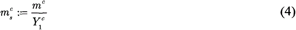
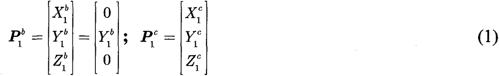
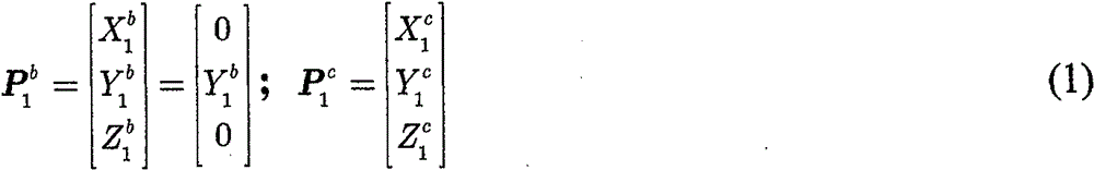
根据基准坐标系的定义,定义


利用移动机器人的平面运动约束,可知Y1 b=Y1 c且为恒值。Using the plane motion constraint of the mobile robot, it can be known that Y 1 b =Y 1 c and it is a constant value.
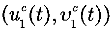
此外,相对于


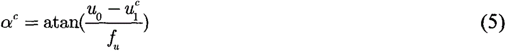
不失一般性,假设

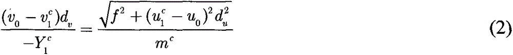
其中(u0,v0)为像素主点,f表示焦距,du,dv为单个像素块分别在xc,yc方向上的长度,经过变换得到:where (u 0 , v 0 ) is the main point of the pixel, f represents the focal length, d u , d v are the lengths of a single pixel block in the x c , y c directions respectively, which are obtained after transformation:

其中fu,fv是以像素大小表示的焦距。由于缺乏场景深度,因而无法估计出mc(t),只能估计出比例意义下的值:where f u , f v are focal lengths expressed in pixel size. Due to the lack of scene depth, m c (t) cannot be estimated, only in a scale sense:
根据
通过当前和初始图像,可以计算出


其中


其中定义


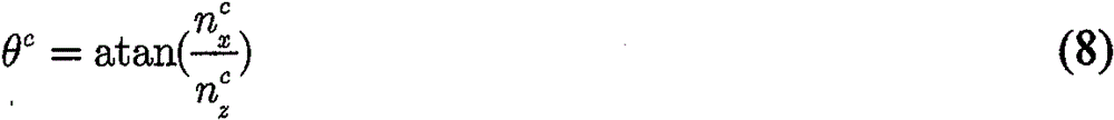
由于xb坐标轴定义为特征点平面与机器人运动平面相交线方向,可知nc(t)垂直于xb坐标轴,并且可知nc(t)在机器人运动平面zcxc的投影与zb坐标轴方向一致。进而可以计算出机器人的方向角θc(t)为:Since the x b coordinate axis is defined as the direction of the intersection line between the feature point plane and the robot motion plane, it can be known that n c (t) is perpendicular to the x b coordinate axis, and it can be known that the projection of n c (t) on the robot motion plane z c x c is the same as z The direction of the b coordinate axis is the same. Then, the direction angle θ c (t) of the robot can be calculated as:

然后,得到φc(t)为:Then, φ c (t) is obtained as:
φc=αc+θc (9)φ c =α c +θ c (9)
因此,可以得到比例意义下的机器人当前位姿
第3,临时坐标系的镇定3. Stabilization of the temporary coordinate system
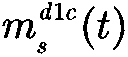
为将机器人镇定到临时坐标系


要注意的是,设置

在本阶段中,首先求取


第3.1,

设置完


附图4显示了


然后,根据如下公式,可以从

θd1c=θc-θd1 (11)θ d1c = θ c - θ d1 (11)


并且可以计算出αd1c(t):αd1c(t)=φd1c(t)-θd1c(t)。And α d1c (t) can be calculated: α d1c (t)=φ d1c (t)−θ d1c (t).
因此,可测得

第3.2,建立机器人运动学方程Section 3.2, Establishing Robot Kinematics Equations
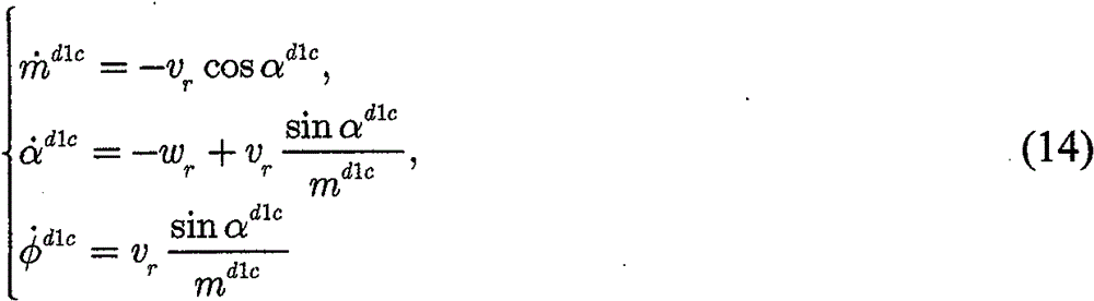
在
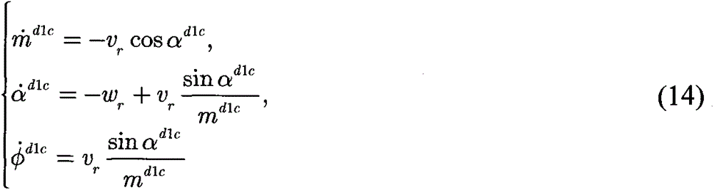
其中vr(t)和ωr(t)分别代表机器人的线速度和角速度。where v r (t) and ω r (t) represent the linear and angular velocities of the robot, respectively.
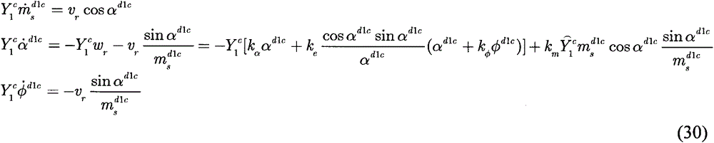
由于机器人位姿只能按比例的方式进行测量,所以可以在(10)带入(14)之后,得到移动机器人模型在比例意义下的运动学方程为:Since the robot pose can only be measured in a proportional way, after (10) is brought into (14), the kinematics equation of the mobile robot model in the sense of scale can be obtained as:
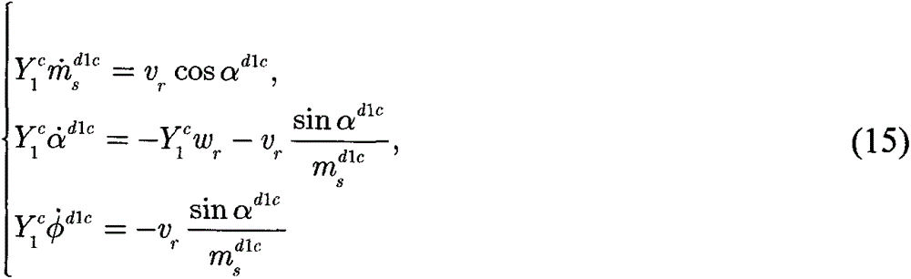
易知,当

第3.3,自适应控制律设计Section 3.3, Adaptive Control Law Design
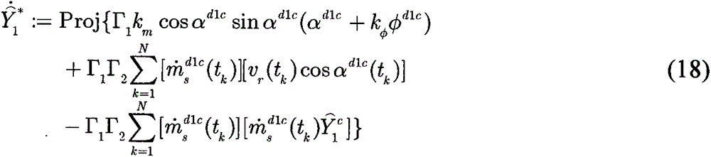
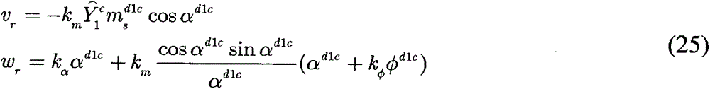
为了实现位姿镇定的目标,通过基于李雅普诺夫的控制设计方法构建移动机器人的线速度和角速度如下:In order to achieve the goal of pose stabilization, the linear and angular velocities of the mobile robot are constructed by the control design method based on Lyapunov as follows:


其中km,kφ,
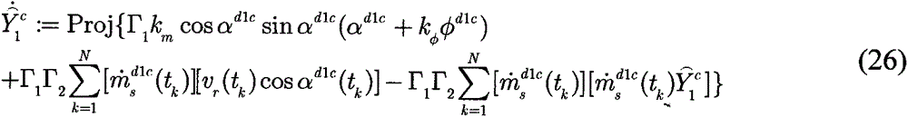
根据并发学习方法,设计自适应更新律为:According to the concurrent learning method, the adaptive update law is designed as:
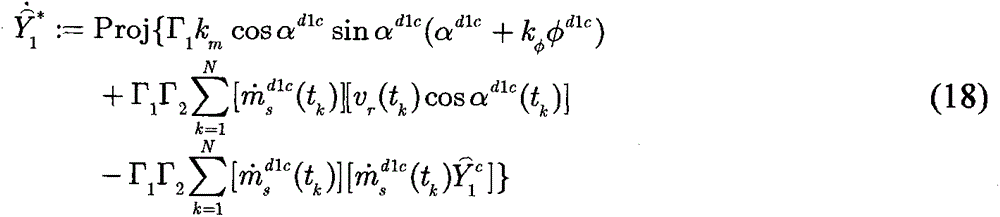
其中

应该注意的是,由于在自适应更新律的并发学习方法中用到了N个采样周期中记录的数据,所以当使用滤波器时就可以得到
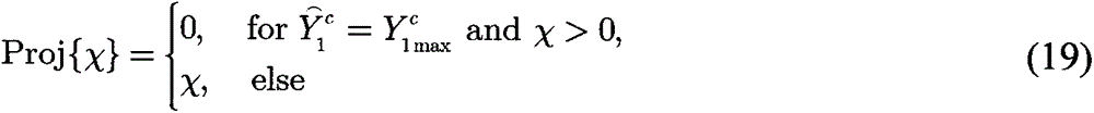
投影函数Proj{χ}定义为:The projection function Proj{χ} is defined as:
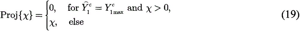
其中
首先,选取


其中

因此,可知当
定理1:当满足如下条件时,控制律(16)和(17)与参数更新律(18)一起将机器人镇定到临时期望位姿:Theorem 1: The control laws (16) and (17) together with the parameter update law (18) stabilize the robot to a temporary desired pose when the following conditions are met:

第4,期望位姿的镇定4. Calmness of the desired pose
在第一阶段后,移动机器人到达临时位姿
对于实际使用中,在笛卡尔坐标系下相对于


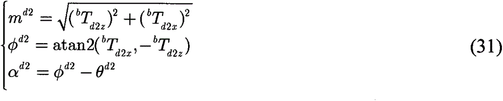
不失一般性,在此阶段中采用了基于极坐标的控制方法。其中,由(md2,αd2,φd2)表示

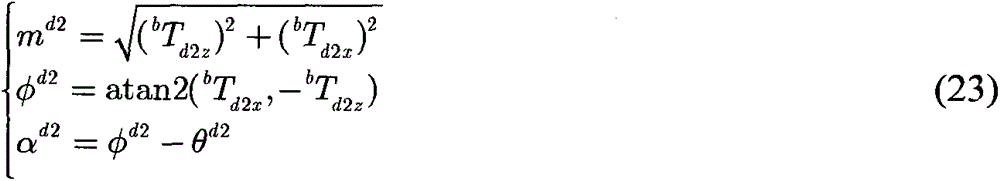
此外,与第3.2中的方法类似,(md2c(t),αd2c(t),φd2c(t))表示

θd2c=θc-θd2 (24)θ d2c = θ c - θ d2 (24)


并且可以计算出αd2c(t):αd2c(t)=φd2c(t)-θd2c(t)。And α d2c (t) can be calculated: α d2c (t)=φ d2c (t)−θ d2c (t).
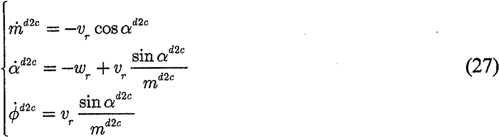
与(14)类似,在

并利用如下控制律将机器人镇定到期望位姿
vr=kmmd2ccosαd2c (28)v r =km m d2c cosα d2c (28)

其中系统误差(md2c(t),αd2c(t),φd2c(t))同时收敛至零。where the systematic errors (m d2c (t), α d2c (t), φ d2c (t)) converge to zero at the same time.
本发明的优点和有益效果Advantages and Benefits of the Invention
本发明提供了一种移动机器人的无期望图像视觉伺服方法。本发明主要做出了以下几方面贡献:1.与采用视觉伺服示教模式的现有方法相比,该方案可以在没有预先记录期望图像的情况下将移动机器人镇定到期望位姿处,使移动机器人系统在非结构化场景中的运行变得更加智能可靠;2.当机器人被驱动到临时期望坐标系时,通过并发学习结构辨识特征高度,从而成功地学习了视觉目标模型,并通过视觉系统对外部环境有了很好的认识;3.为了代替期望图像,对视觉目标的所有坐标进行详细定义,为移动机器人定位和位姿镇定提供参考。The present invention provides an undesired image visual servo method for a mobile robot. The present invention mainly makes the following contributions: 1. Compared with the existing method using the visual servo teaching mode, this solution can stabilize the mobile robot to the desired pose without pre-recording the desired image, so that the The operation of the mobile robot system in unstructured scenes becomes more intelligent and reliable; 2. When the robot is driven to the temporary desired coordinate system, the feature height is identified through concurrent learning of the structure, so that the visual target model is successfully learned, and the visual target model is successfully learned. The system has a good understanding of the external environment; 3. In order to replace the desired image, all coordinates of the visual target are defined in detail to provide a reference for the positioning and pose stabilization of the mobile robot.
附图说明:Description of drawings:
图1为无期望图视觉伺服任务的坐标系关系;Fig. 1 is the coordinate system relationship of the undesired graph visual servoing task;
图2为视觉伺服策略框图;Figure 2 is a block diagram of the visual servoing strategy;
图3为基准坐标系的定义;Figure 3 is the definition of the reference coordinate system;
图4为

图5为仿真结果:移动机器人的特征点和运动轨迹[加粗三角形:期望和临时期望位姿];Figure 5 shows the simulation results: feature points and motion trajectories of the mobile robot [bold triangle: desired and temporary desired pose];
图6为仿真结果:机器人位姿的变化[实线:机器人位姿;虚线:期望位姿];Figure 6 shows the simulation results: changes in the robot pose [solid line: robot pose; dashed line: desired pose];
图7为仿真结果:由参数更新律(18)得到的

图8表示实验结果:移动机器人的运动轨迹[加粗三角形:两个阶段的期望和临时期望位姿];Figure 8 shows the experimental results: the motion trajectory of the mobile robot [bold triangle: desired and temporary desired poses in two stages];
图9表示实验结果:机器人位姿的变化[实线:机器人位姿;虚线:期望值(0)];Figure 9 shows the experimental results: the change of the robot pose [solid line: robot pose; dashed line: expected value (0)];
图10表示实验结果:两个阶段的系统误差的变化[实线:误差值;虚线:期望值(0)];Fig. 10 shows the experimental results: the variation of the systematic error in two stages [solid line: error value; dashed line: expected value (0)];
图11表示实验结果:通过参数更新律得到的

图12表示实验结果:移动机器人的速度;Figure 12 shows the experimental results: the speed of the mobile robot;
图13表示实验结果:特征点的图像轨迹[星点:阶段一的最终图像;方形点:阶段二的最终图像];Figure 13 shows the experimental results: image trajectories of feature points [star points: final image of stage one; square points: final image of stage two];
具体实施方式:Detailed ways:
实施例1Example 1
第1,定义系统坐标系First, define the system coordinate system
第1.1,系统坐标系的描述Section 1.1, Description of the System Coordinate System
基于视觉目标定义了基准坐标系


以

第1.2,控制方案Section 1.2, Control Scheme
根据坐标系定义,本文的目的是提出一种新颖的视觉伺服方案来驱动移动机器人,使坐标系


在阶段1中,首先为移动机器人的临时镇定设置比例意义下的期望位姿。然后通过极坐标系表示方法设计自适应调节控制器,以将机器人镇定至坐标系
在阶段2中,利用辨识特征高度来获取移动机器人的全状态信息。然后,采用基于极坐标的调节控制器来驱动机器人到
第2,构造系统模型Second, construct the system model
第2.1,基准坐标系的定义Section 2.1, Definition of Datum Coordinate System
基于视觉目标定义基准坐标系,其要求特征点


zcxc平面与特征平面的交线定义为xb轴。定义zb的方向与
基于坐标系


第2.2,可测量信号Section 2.2, Measurable Signals
根据基准坐标系的定义,定义


利用移动机器人的平面运动约束,可知Y1 b=Y1 c且为恒值。Using the plane motion constraint of the mobile robot, it can be known that Y 1 b =Y 1 c and it is a constant value.
此外,相对于

不失一般性,假设
其中(u0,v0)为像素主点,f表示焦距,du,dv为单个像素块分别在xc,yc方向上的长度,经过变换得到:where (u 0 , v 0 ) is the main point of the pixel, f represents the focal length, d u , d v are the lengths of a single pixel block in the x c , y c directions respectively, which are obtained after transformation:
其中fu,fv是以像素大小表示的焦距。由于缺乏场景深度,因而无法估计出mc(t),只能估计出比例意义下的值:where f u , f v are focal lengths expressed in pixel size. Due to the lack of scene depth, m c (t) cannot be estimated, only in a scale sense:
根据
通过当前和初始图像,可以计算出


其中


其中定义


由于xb坐标轴定义为特征点平面与机器人运动平面相交线方向,可知nc(t)垂直于xb坐标轴,并且可知nc(t)在机器人运动平面zcxc的投影与zb坐标轴方向一致。进而可以计算出机器人的方向角θc(t)为:Since the x b coordinate axis is defined as the direction of the intersection line between the feature point plane and the robot motion plane, it can be known that n c (t) is perpendicular to the x b coordinate axis, and it can be known that the projection of n c (t) on the robot motion plane z c x c is the same as z The direction of the b coordinate axis is the same. Then, the direction angle θ c (t) of the robot can be calculated as:
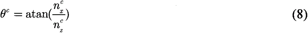
然后,得到φc(t)为:Then, φ c (t) is obtained as:
φc=αc+θc (9)φ c =α c +θ c (9)
因此,可以得到比例意义下的机器人当前位姿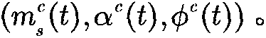
第3,临时坐标系的镇定3. Stabilization of the temporary coordinate system
为将机器人镇定到临时坐标系


要注意的是,设置

在本阶段中,首先求取


第3.1,

设置完


附图4显示了


然后,根据如下公式,可以从

θd1c=θc-θd1 (11)θ d1c = θ c - θ d1 (11)


并且可以计算出αd1c(t):αd1c(t)=φd1c(t)-θd1c(t)。And α d1c (t) can be calculated: α d1c (t)=φ d1c (t)−θ d1c (t).
因此,可测得


第3.2,建立机器人运动学方程Section 3.2, Establishing Robot Kinematics Equations
在

其中vr(t)和ωr(t)分别代表机器人的线速度和角速度。where v r (t) and ω r (t) represent the linear and angular velocities of the robot, respectively.
由于机器人位姿只能按比例的方式进行测量,所以可以在(10)带入(14)之后,得到移动机器人模型在比例意义下的运动学方程为:Since the robot pose can only be measured in a proportional way, after (10) is brought into (14), the kinematics equation of the mobile robot model in the sense of scale can be obtained as:
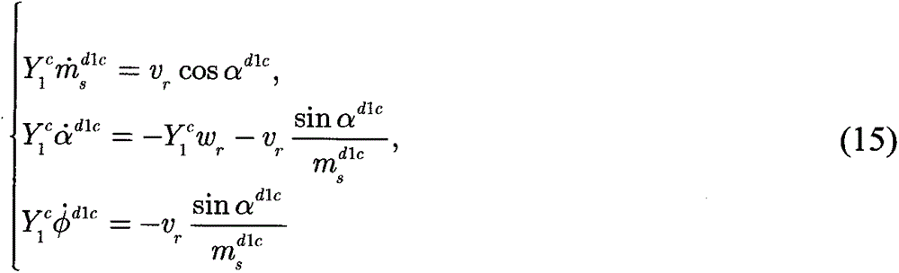
易知,当

第3.3,自适应控制律设计Section 3.3, Adaptive Control Law Design
为了实现位姿镇定的目标,通过基于李雅普诺夫的控制设计方法构建移动机器人的线速度和角速度如下:In order to achieve the goal of pose stabilization, the linear and angular velocities of the mobile robot are constructed by the control design method based on Lyapunov as follows:


其中km,kφ,
根据并发学习方法,设计自适应更新律为:According to the concurrent learning method, the adaptive update law is designed as:
其中

应该注意的是,由于在自适应更新律的并发学习方法中用到了N个采样周期中记录的数据,所以当使用滤波器时就可以得到
投影函数Proj{χ}定义为:The projection function Proj{χ} is defined as:
其中
首先,选取


其中

因此,可知当
定理1:当满足如下条件时,控制律(16)和(17)与参数更新律(18)一起将机器人镇定到临时期望位姿:Theorem 1: The control laws (16) and (17) together with the parameter update law (18) stabilize the robot to a temporary desired pose when the following conditions are met:

第4,定理1证明Fourth, the proof of
本发明在此给出定理1的证明。The present invention provides a proof of
证明:首先定义Lyapunov候选函数为:Proof: First define the Lyapunov candidate function as:

对上式关于时间求导有:The derivative of the above formula with respect to time has:

即控制律设计为:That is, the control law is designed as:
根据并发学习方法,设计深度辨识的自适应更新律为:According to the concurrent learning method, the adaptive update law for deep identification is designed as:
其中定义了深度辨识误差为

因而有


在绝大多数情况下,上式处于“=”状态;符号>出现在Proj[χ]=0的情况。In most cases, the above formula is in the "=" state; the symbol > appears in the case of Proj[χ]=0.
将式(26)代入(24)可得:Substitute equation (26) into (24) to get:

将控制律代入,闭环误差方程可写为:Substituting the control law, the closed-loop error equation can be written as:
由于设计了投影函数,因而可以保证


定义


因此可知Θ中的最大不变集M为

第5,期望位姿的镇定5. Calmness of the desired pose
在第一阶段后,移动机器人到达临时位姿
对于实际使用中,在笛卡尔坐标系下相对于


不失一般性,在此阶段中采用了基于极坐标的控制方法。其中,由(md2,αd2,φd2)表示

此外,与第3.2中的方法类似,(md2c(t),αd2c(t),φd2c(t))表示

θd2c=θc-θd2 (32)θ d2c = θ c - θ d2 (32)


并且可以计算出αd2c(t):αd2c(t)=φd2c(t)-θd2c(t)。And α d2c (t) can be calculated: α d2c (t)=φ d2c (t)−θ d2c (t).
与(14)类似,在

并利用如下控制律将机器人镇定到期望位姿
vr=kmmd2ccosαd2c (36)v r = km m d2c cosα d2c (36)

其中系统误差(md2c(t),αd2c(t),φd2c(t))同时收敛至零。where the systematic errors (m d2c (t), α d2c (t), φ d2c (t)) converge to zero at the same time.
第6,仿真和实验结果
第6.1,仿真结果Section 6.1, Simulation Results
在这部分中,本发明提供了仿真结果来验证所提出的方法的性能。首先,随机设置四个平面特征点,并将
对应于基准坐标系,设置期望位姿为(bTd2z,bTd2x,θd2)=(-1.6m,0.1m,0°),且将移动机器人的初始位姿设置为(bT0z,bT0x,θ0)=(-6.5m,-0.8m,27°)。在极坐标中设置临时期望位姿为
设置控制参数为km=0.1,kα=0.4,kφ=2,Γ1=3,Γ2=0.001。随机选取

图5给出了移动机器人在笛卡尔空间中的运动路径结果,其中加粗三角形分别表示期望位姿和临时位姿。其特征点也在该图中示出,其中利用圆点作为参考。可以看出机器人有效地移动到期望位姿处,并且路径在两个阶段中都非常平滑。图6表示机器人当前位姿(bTcz(t),bTcx(t),θc(t))的变化,其中虚线表示期望坐标系

第6.2,实验结果Section 6.2, Experimental Results
在这部分中,本发明给出了实验结果以验证设计方案的性能,其中采用了携带CCD照相机的Pioneer3-DX移动机器人以及在两个正方形的共顶点处的四个特征平面。整个方案是通过使用Visual Studio环境和OpenCV库实现的。采样频率为50Hz,满足视觉伺服任务的实时性要求。In this section, the present invention presents experimental results to verify the performance of the design scheme using a Pioneer3-DX mobile robot carrying a CCD camera and four feature planes at the common vertices of two squares. The whole scheme is implemented by using the Visual Studio environment and the OpenCV library. The sampling frequency is 50Hz, which meets the real-time requirements of visual servo tasks.
将移动机器人的期望位姿设置为(bTd2z,bTd2x,θd2)=(-1.1m,0m,0°),并且初始位姿随机设置在(bT0z,bT0x,θ0)=(-3.6m,1.1m,26°)处。将临时期望位姿设置为
图8表示移动机器人两个阶段的混合路径。图9表示机器人当前位姿(bTcz(t),bTcx(t),θc(t))的变化。图10表示阶段一中的系统误差和阶段二中的md2c(t)。可以看出,机器人以较小的稳态误差通过高效的路径到达期望和临时期望位姿。Figure 8 shows the hybrid path of the two phases of the mobile robot. FIG. 9 shows changes in the current pose ( b T cz (t), b T cx (t), θ c (t)) of the robot. Figure 10 shows the systematic error in stage one and m d2c (t) in stage two. It can be seen that the robot reaches the desired and temporary desired poses through an efficient path with a small steady-state error.
此外,为了测试特征高度辨识的精度,本发明根据初始和当前图像信息以及某些特征点之间的已知度量距离来计算Y1 c的真实值。由于


图12表示移动机器人的速度。图13表示特征点的图像轨迹,其中圆点表示初始图像中提取的特征点,星形表示阶段一中的最终图像,正方形是阶段二中的最终图像。Fig. 12 shows the speed of the mobile robot. Figure 13 shows the image trajectories of the feature points, where the circles represent the feature points extracted from the initial image, the stars represent the final images in stage one, and the squares are the final images in stage two.
可以得出结论,这个实验设备适合于探索未知物体,在这种意义上,首先将机器人镇定到相对于目标物体粗略设置的比例意义下的位姿,然后将机器人镇定到易于观察的离目标物体更近的精确的位姿。It can be concluded that this experimental device is suitable for exploring unknown objects, in the sense that the robot is first stabilized to a pose in a sense of scale relative to the target object, which is roughly set, and then the robot is stabilized to an easily observable distance from the target object. Closer precise pose.
Claims (1)


Priority Applications (1)
| Application Number | Priority Date | Filing Date | Title |
|---|---|---|---|
| CN201710885886.6A CN109542094B (en) | 2017-09-21 | 2017-09-21 | Visual Stabilization Control of Mobile Robots with Unexpected Images |
Applications Claiming Priority (1)
| Application Number | Priority Date | Filing Date | Title |
|---|---|---|---|
| CN201710885886.6A CN109542094B (en) | 2017-09-21 | 2017-09-21 | Visual Stabilization Control of Mobile Robots with Unexpected Images |
Publications (2)
| Publication Number | Publication Date |
|---|---|
| CN109542094A CN109542094A (en) | 2019-03-29 |
| CN109542094B true CN109542094B (en) | 2021-06-08 |
Family
ID=65830739
Family Applications (1)
| Application Number | Title | Priority Date | Filing Date |
|---|---|---|---|
| CN201710885886.6A Expired - Fee Related CN109542094B (en) | 2017-09-21 | 2017-09-21 | Visual Stabilization Control of Mobile Robots with Unexpected Images |
Country Status (1)
| Country | Link |
|---|---|
| CN (1) | CN109542094B (en) |
Families Citing this family (5)
| Publication number | Priority date | Publication date | Assignee | Title |
|---|---|---|---|---|
| CN112123370B (en) * | 2019-06-24 | 2024-02-06 | 内蒙古汇栋科技有限公司 | Mobile robot vision stabilization control with desired pose change |
| CN112363528B (en) * | 2020-10-15 | 2022-06-14 | 北京理工大学 | Unmanned aerial vehicle anti-interference cluster formation control method based on airborne vision |
| US11429112B2 (en) * | 2020-12-31 | 2022-08-30 | Ubtech North America Research And Development Center Corp | Mobile robot control method, computer-implemented storage medium and mobile robot |
| CN115502972B (en) * | 2022-09-16 | 2025-06-13 | 深圳市优必选科技股份有限公司 | A control method, a control device, a robot and a storage medium |
| CN115562304B (en) * | 2022-11-01 | 2026-02-03 | 河海大学常州校区 | Mobile robot vision servo control method and system based on depth point cloud |
Citations (4)
| Publication number | Priority date | Publication date | Assignee | Title |
|---|---|---|---|---|
| CN102855620A (en) * | 2012-07-13 | 2013-01-02 | 南开大学 | Pure rotation camera self-calibration method based on spherical projection model |
| US9146561B2 (en) * | 2013-12-03 | 2015-09-29 | King Fahd University Of Petroleum And Minerals | Robotic leader-follower navigation and fleet management control method |
| CN104950893A (en) * | 2015-06-26 | 2015-09-30 | 浙江大学 | Homography matrix based visual servo control method for shortest path |
| CN106774309A (en) * | 2016-12-01 | 2017-05-31 | 天津工业大学 | A kind of mobile robot is while visual servo and self adaptation depth discrimination method |
-
2017
- 2017-09-21 CN CN201710885886.6A patent/CN109542094B/en not_active Expired - Fee Related
Patent Citations (4)
| Publication number | Priority date | Publication date | Assignee | Title |
|---|---|---|---|---|
| CN102855620A (en) * | 2012-07-13 | 2013-01-02 | 南开大学 | Pure rotation camera self-calibration method based on spherical projection model |
| US9146561B2 (en) * | 2013-12-03 | 2015-09-29 | King Fahd University Of Petroleum And Minerals | Robotic leader-follower navigation and fleet management control method |
| CN104950893A (en) * | 2015-06-26 | 2015-09-30 | 浙江大学 | Homography matrix based visual servo control method for shortest path |
| CN106774309A (en) * | 2016-12-01 | 2017-05-31 | 天津工业大学 | A kind of mobile robot is while visual servo and self adaptation depth discrimination method |
Non-Patent Citations (2)
| Title |
|---|
| Image Feature based Navigation of Nonholonomic;Satoshi Komada等;《The International Federation of Automatic Control》;20081231;全文 * |
| 移动机器人主动视觉伺服技术研究;刘玺;《中国优秀硕士学位论文全文数据库 信息科技辑》;20110115;全文 * |
Also Published As
| Publication number | Publication date |
|---|---|
| CN109542094A (en) | 2019-03-29 |
Similar Documents
| Publication | Publication Date | Title |
|---|---|---|
| CN109542094B (en) | Visual Stabilization Control of Mobile Robots with Unexpected Images | |
| Motlagh et al. | Position Estimation for Drones based on Visual SLAM and IMU in GPS-denied Environment | |
| Zhao et al. | Vision-based tracking control of quadrotor with backstepping sliding mode control | |
| Gur fil et al. | Partial aircraft state estimation from visual motion using the subspace constraints approach | |
| Liu et al. | Scale-only visual homing from an omnidirectional camera | |
| Henawy et al. | Accurate IMU factor using switched linear systems for VIO | |
| CN109960145B (en) | Mobile robot mixed vision trajectory tracking strategy | |
| Xie et al. | Dynamic IBVS of a rotary wing UAV using line features | |
| Li et al. | Bridging the gap between visual servoing and visual SLAM: A novel integrated interactive framework | |
| Silveira | On intensity-based nonmetric visual servoing | |
| MacKunis et al. | Unified tracking and regulation visual servo control for wheeled mobile robots | |
| Fahimi et al. | An alternative closed-loop vision-based control approach for unmanned aircraft systems with application to a quadrotor | |
| Wang et al. | Ego-motion estimation of a quadrotor based on nonlinear observer | |
| Das et al. | Calibration of a dynamic camera cluster for multi-camera visual SLAM | |
| Boucheloukh et al. | UAV navigation based on adaptive fuzzy backstepping controller using visual odometry | |
| Roque et al. | Multi-agent formation control using epipolar constraints | |
| TWI788253B (en) | Adaptive mobile manipulation apparatus and method | |
| CN110722547A (en) | Robot vision stabilization under model unknown dynamic scene | |
| Elsheikh et al. | Practical path planning and path following for a non-holonomic mobile robot based on visual servoing | |
| Scherer et al. | DCTAM: Drift-corrected tracking and mapping for autonomous micro aerial vehicles | |
| Keshmiri | Image based visual servoing using trajectory planning and augmented visual servoing controller | |
| Siradjuddin et al. | An image based visual control law for a differential drive mobile robot | |
| Wang et al. | Real-time visual odometry estimation based on principal direction detection on ceiling vision | |
| Shanahan et al. | Visual servoing control for robot manipulators | |
| CN120627899B (en) | Robot control method, device, computer equipment and storage medium |
Legal Events
| Date | Code | Title | Description |
|---|---|---|---|
| PB01 | Publication | ||
| PB01 | Publication | ||
| SE01 | Entry into force of request for substantive examination | ||
| SE01 | Entry into force of request for substantive examination | ||
| GR01 | Patent grant | ||
| GR01 | Patent grant | ||
| CF01 | Termination of patent right due to non-payment of annual fee | ||
| CF01 | Termination of patent right due to non-payment of annual fee |
Granted publication date: 20210608 |